WO2013124881A1 - Procédé de communication sans fil, système de communication sans fil, station radio et terminal radio - Google Patents
Procédé de communication sans fil, système de communication sans fil, station radio et terminal radio Download PDFInfo
- Publication number
- WO2013124881A1 WO2013124881A1 PCT/JP2012/001127 JP2012001127W WO2013124881A1 WO 2013124881 A1 WO2013124881 A1 WO 2013124881A1 JP 2012001127 W JP2012001127 W JP 2012001127W WO 2013124881 A1 WO2013124881 A1 WO 2013124881A1
- Authority
- WO
- WIPO (PCT)
- Prior art keywords
- node
- wireless terminal
- signal
- information
- wireless
- Prior art date
- Legal status (The legal status is an assumption and is not a legal conclusion. Google has not performed a legal analysis and makes no representation as to the accuracy of the status listed.)
- Ceased
Links
Images






Classifications
-
- H—ELECTRICITY
- H04—ELECTRIC COMMUNICATION TECHNIQUE
- H04W—WIRELESS COMMUNICATION NETWORKS
- H04W52/00—Power management, e.g. Transmission Power Control [TPC] or power classes
- H04W52/04—Transmission power control [TPC]
- H04W52/38—TPC being performed in particular situations
- H04W52/50—TPC being performed in particular situations at the moment of starting communication in a multiple access environment
-
- H—ELECTRICITY
- H04—ELECTRIC COMMUNICATION TECHNIQUE
- H04W—WIRELESS COMMUNICATION NETWORKS
- H04W52/00—Power management, e.g. Transmission Power Control [TPC] or power classes
- H04W52/04—Transmission power control [TPC]
- H04W52/18—TPC being performed according to specific parameters
- H04W52/24—TPC being performed according to specific parameters using SIR [Signal to Interference Ratio] or other wireless path parameters
- H04W52/246—TPC being performed according to specific parameters using SIR [Signal to Interference Ratio] or other wireless path parameters where the output power of a terminal is based on a path parameter calculated in said terminal
-
- H—ELECTRICITY
- H04—ELECTRIC COMMUNICATION TECHNIQUE
- H04W—WIRELESS COMMUNICATION NETWORKS
- H04W76/00—Connection management
- H04W76/10—Connection setup
Definitions
- the present invention relates to a wireless communication method, a wireless communication system, a wireless station, and a wireless terminal.
- next-generation wireless communication technologies have been discussed in order to further increase the speed and capacity of wireless communication in wireless communication systems such as mobile phone systems.
- 3GPP 3rd Generation Partnership Project
- LTE Long Term Evolution
- LTE-A LTE-Advanced
- coordinated multipoint (hereinafter also referred to as CoMP) communication is being studied in order to reduce inter-cell interference and improve received signal strength.
- multipoint cooperative communication a plurality of geographically separated points (hereinafter also referred to as nodes) perform communication in cooperation. Each point corresponds to, for example, a base station, a communication unit, an antenna, or a cell formed by these. Thereby, dynamic adjustment of transmission or reception between multiple points is performed.
- downlink multipoint cooperative communication a method of jointly transmitting a plurality of points to a wireless terminal has been studied.
- uplink multipoint cooperative communication a method of combining signals received at a plurality of points while communicating between the points has been studied.
- the disclosed technology has been made in view of the above, and provides a wireless communication method, a wireless communication system, a wireless station, and a wireless terminal capable of improving transmission control characteristics in multipoint cooperative communication. Objective.
- a wireless communication method disclosed in the present application is a wireless communication including a wireless terminal in which one cell includes a plurality of nodes and capable of cooperative communication with one or more nodes.
- a wireless communication method in a system wherein, in the cell, before establishing a connection with the wireless terminal, information on a reference signal for each node is notified to the wireless terminal, and the wireless terminal refers to the node for each node.
- a signal for establishing the connection is transmitted with a parameter corresponding to the communication quality of each node acquired using information related to the signal.
- FIG. 1 is a diagram illustrating a configuration of a wireless communication system according to the first embodiment.
- FIG. 2 is a functional block diagram showing the configuration of the radio station according to the first embodiment.
- FIG. 3 is a functional block diagram showing the configuration of the wireless terminal according to the first embodiment.
- FIG. 4 is a diagram illustrating a hardware configuration of the radio station according to the first embodiment.
- FIG. 5 is a diagram illustrating a hardware configuration of the wireless terminal according to the first embodiment.
- FIG. 6 is a sequence diagram for explaining the operation of the wireless communication system according to the first embodiment.
- FIG. 7 is a diagram illustrating a configuration of a wireless communication system according to the second embodiment.
- FIG. 8 is a functional block diagram showing a configuration of a radio station according to the second embodiment.
- FIG. 1 is a diagram illustrating a configuration of a wireless communication system according to the first embodiment.
- FIG. 2 is a functional block diagram showing the configuration of the radio station according to the first embodiment.
- FIG. 3
- FIG. 9 is a functional block diagram showing the configuration of the wireless terminal according to the second embodiment.
- FIG. 10 is a sequence diagram for explaining the operation of the wireless communication system according to the second embodiment.
- FIG. 11 is a diagram illustrating an example of control information in the wireless communication system according to the second embodiment.
- FIG. 12 is a flowchart for explaining the operation of the radio communication system according to the third embodiment.
- FIG. 13 is a flowchart for explaining the operation of the wireless communication system according to the fourth embodiment.
- FIG. 14 is a diagram illustrating an example of control information in the wireless communication system according to the fourth embodiment.
- FIG. 15 is a diagram illustrating an example of control information in the wireless communication system according to the fourth embodiment.
- FIG. 16 is a diagram illustrating an example of control information in the wireless communication system according to the fourth embodiment.
- FIG. 17 is a diagram illustrating an example of control information in the wireless communication system according to the fourth embodiment.
- FIG. 1 shows a configuration of a wireless communication system 1 according to the first embodiment.
- the wireless communication system 1 includes a wireless station 4 and wireless terminals 7 and 8.
- the radio station 4 is connected to the host device 3 via a wired connection, and the host device 3 is connected to the network 2 via a wired connection.
- the radio station 4 has a control unit 9 and remote units 5 and 6.
- the control unit 9 can be realized as eNodeB (evolved (Node B), for example.
- the remote units 5 and 6 can be realized as, for example, RRH (Remote Radio Radio Head) included in the eNodeB.
- the control unit 9, the remote unit 5, and the remote unit 6 each have an antenna (point) and are arranged at points separated from each other.
- the control unit 9 and the remote units 5 and 6 correspond to nodes.
- the control unit 9 forms a cell C1, and the remote units 5 and 6 form cover areas R1 and R2 that overlap the cell C1, respectively.
- the wireless terminals 7 and 8 are located in the cell C1. At this time, the wireless terminal 7 is included in the cover area R1.
- the control unit 9 and the remote units 5 and 6 communicate with each other via a wired connection and also perform CoMP communication with the wireless terminals 7 and 8.
- data is transmitted from one or more nodes selected as a set to be used for downlink CoMP communication among the control unit 9 and the remote units 5 and 6 to the radio terminal 7.
- Send the combined
- one or more nodes selected as a set to be used for uplink CoMP communication among the control unit 9 and the remote units 5 and 6 are transmitted from the radio terminal 7. Are received, and the received signal is synthesized between the nodes.
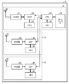
- FIG. 2 is a functional block diagram showing the configuration of the wireless station 4.
- the control unit 9 of the wireless station 4 includes an antenna 10, a transmission unit 11, a reception unit 12, and a control unit 13.
- the remote unit 5 of the wireless station 4 includes an antenna 14, a transmission unit 15, and a reception unit 16.
- the remote unit 6 of the wireless station 4 includes an antenna 17, a transmission unit 18, and a reception unit 19. Prepare. Each of these components is connected so that signals and data can be input and output in one direction or in both directions.
- the constituent parts 14 to 19 of the remote units 5 and 6 are the same as the constituent antennas 14 to 16 of the control unit 9.
- the transmission unit 11 transmits data signals and control signals via the antenna 11.
- the signal to be transmitted includes, for example, information on a reference signal for each cell, information on a reference signal for each node, a reference signal for each cell, a reference signal for each node, and a parameter for setting uplink transmission power.
- the receiving unit 12 receives data signals and control signals transmitted from the wireless terminals 7 and 8 via the antenna 11.
- the received signal includes, for example, a signal for establishing a connection.
- the antenna 11 may be separated for transmission and reception.
- the control unit 13 acquires information and signals from the host device 3 and other wireless stations via a wired connection or a wireless connection.
- the control unit 13 outputs data to be transmitted and control information to the transmission units 11, 15 and 18.
- the control unit 13 inputs received data and control information from the receiving units 12, 16, and 19.
- the control unit 13 notifies the system information in the cell C1.
- the system information is broadcast on a broadcast channel or a shared channel designated by the broadcast channel.
- the system information includes, for example, information related to the reference signal for each cell and information related to the reference signal for each node.
- the control unit 13 causes the transmission units 11, 15, and 18 to transmit a reference signal.
- the transmission unit 11 uses a reference signal for each cell as a reference signal for measuring communication quality, and the transmission units 15 and 18 each use the remote unit 5 as a reference signal for measuring communication quality.
- 6 is used as a reference signal for each node.
- FIG. 3 is a functional block diagram showing the configuration of the wireless terminal 7.
- the wireless terminal 7 includes an antenna 20, a transmission unit 21, a reception unit 22, and a control unit 23. Each of these components is connected so that signals and data can be input and output in one direction or in both directions.
- the functional configuration and hardware configuration of the wireless terminal 8 are the same as the functional configuration and hardware configuration of the wireless terminal 7.
- the transmission unit 21 transmits a data signal and a control signal via the antenna 20.
- the signal to be transmitted includes, for example, a signal for establishing a connection.
- the receiving unit 12 receives the data signal and the control signal transmitted from the wireless terminal via the antenna 20.
- the received signal includes, for example, information on a reference signal for each cell, information on a reference signal for each node, a reference signal for each cell, a reference signal for each node, and a parameter for determining uplink transmission power.
- the antenna 20 may be separated for transmission and reception.
- the control unit 23 outputs data to be transmitted and control information to the transmission unit 21.
- the control unit 23 inputs data and control information received from the receiving unit 22.
- the control unit 23 determines, based on the received information on the reference signal for each cell and the information on the reference signal for each node, from the received signal of the entire reference signal transmitted from the wireless station 4 for each node before connection establishment.
- the reference signal reception level is acquired, and the communication quality for each node is acquired.
- the control unit 23 determines the transmission power of a signal for establishing a connection from the acquired communication quality for each node.
- FIG. 4 is a diagram illustrating a hardware configuration of the wireless station 4.
- the wireless station 4 includes, as hardware components, for example, RF circuits (Radio Frequency) 31, 38, and 42 including antennas 30, 37, and 41 and DSPs (Digital Signal Processors) 32 and 39. , 43, a CPU (Central Processing Unit) 34, memories 33, 35, 40, and 44, and a network IF (Interface) 36.
- the CPU 34 is connected through a network IF 36 such as a switch so that various signals and data can be input and output.
- the memories 33, 35, 40, and 44 include, for example, at least one of RAM (Random Access Memory), ROM (Read Only Memory), and flash memory such as SDRAM (Synchronous Dynamic Random Access Memory). Store the data.
- the transmitters 11, 15, 18 and the receivers 12, 16, 19 are realized by integrated circuits such as RF circuits 31, 38, 42 and DSPs 32, 39, 43, for example.
- the control unit 13 is realized by an integrated circuit such as a CPU 34, for example.
- the control unit 9 corresponds to the components 30 to 36
- the remote unit 5 corresponds to the components 37 to 40
- the remote unit 6 corresponds to the components 41 to 44.
- FIG. 5 is a diagram illustrating a hardware configuration of the wireless terminal 7.
- the wireless terminal 7 includes, as hardware components, an RF circuit 51 including an antenna 50, a CPU 52, and a memory 53, for example.
- RF circuit 51 including an antenna 50
- CPU 52 a CPU 52
- memory 53 for example.
- LCD Liquid Crystal Display
- the memory 53 includes, for example, RAM such as SDRAM, ROM, and flash memory, and stores programs, control information, and data.
- the transmission unit 21 and the reception unit 22 are realized by the RF circuit 51, for example.
- the control unit 23 is realized by an integrated circuit such as a CPU 52, for example.
- FIG. 6 is a sequence diagram for explaining an operation related to connection establishment of the wireless communication system 1.
- the control unit 9, the remote unit 5, and the remote unit 6 of the wireless station 4 are provided as nodes so that CoMP communication is possible.
- the cell identification information is common. That is, the cell identification information is common to the control unit 9 and the remote units 5 and 6. Then, a reference signal for each cell is assigned in association with the cell identification information.
- Cell identification information or the like of the cell C1 is broadcast in the cell C1 as system information, for example.
- the wireless terminal 7 converts the reference signals transmitted from the control unit 9 and the remote units 5 and 6 to the same pattern. Therefore, it cannot be separated for each transmission source, and is received as a synthesized signal. Then, the wireless terminal 7 acquires the communication quality based on the reception level of the combined signal and determines the transmission power. In this case, an appropriate transmission power may not be determined.
- the wireless terminal 7 acquires the communication quality for each node using the reception level of the reference signal for each node. And the radio
- the wireless terminal 7 in order to acquire the reception level separately from the reference signal for each node, it is necessary for the wireless terminal 7 to acquire information regarding the reference signal for each node in advance.
- the wireless terminal 7 periodically transmits information on the reference signal for each node as wireless resource information from a connected wireless station via an individual control channel or data channel. Can be obtained. And it is possible to acquire communication quality for every node using the reception level of the reference signal for every node, and to determine transmission power.
- the wireless terminal 7 cannot acquire information on the reference signal for each node through the individual control channel or data channel as the wireless resource information. For this reason, before the connection is established, the control unit 9 and the remote units 5 and 6 each transmit a common reference signal for each cell. The wireless terminal 7 receives the reference signal transmitted from the control unit 9 and the remote units 5 and 6 as a synthesized signal. Then, the wireless terminal 7 acquires the communication quality based on the reception level of the signal synthesized in this way, and determines the initial transmission power of the signal for establishing the connection. Then, after establishing a communication link with the cell C1, the wireless terminal 7 acquires wireless resource information, and shifts to CoMP communication with a node included in the cell C1.
- the radio terminal 7 is a signal for establishing a connection with a relatively large initial transmission power so that a signal for establishing a connection reaches the entire cell C1 in order to establish a communication link with the cell C1. Is assumed to be sent. Then, for example, there is a risk of interference or contention for the wireless terminal 8 that is located in the cell C1 and tries to establish a connection.
- an operation for establishing a connection is performed as follows.
- the wireless terminal 7 located in the cell C1 is in a state where the connection with the wireless station 4 has not been established, and an operation of establishing a connection between the wireless station 4 and the wireless terminal 7 will be described as an example.
- the radio station 4 broadcasts information on the reference signal for each node in the cell C1 (S1).
- information on the reference signal for each node is included in the system information and is broadcast on a broadcast channel or a shared channel in which radio resources are specified by the broadcast channel.
- the broadcast channel designates a time position, a frequency position, and the like at which system information is transmitted on the shared channel.
- the radio station 4 may transmit system information from the control unit 9 or may transmit it from all of the control unit 9 and the remote units 5 and 6, for example.
- the information on the reference signal for each node includes, for example, information on the reference signal associated with each node included in the cell C1.
- the radio terminal 7 receives information on the reference signal for each node broadcast in the cell C1. Since the information related to the reference signal for each node is broadcast in the cell C1, the wireless terminal 7 located in the cell C1 can acquire the information related to the reference signal for each node before establishing the connection.
- the wireless station 4 transmits a reference signal for each node (S2).
- the reference signal is transmitted using a predetermined radio resource.
- the remote units 5 and 6 of the wireless station 4 transmit reference signals assigned to the remote units 5 and 6, respectively, and the control unit 9 of the wireless station 4 transmits reference signals assigned to the entire cell. May be. Thereby, different reference signals are transmitted between the control unit 9 and the remote units 5 and 6.
- the radio terminal 7 separates the reference signal transmitted from the radio station 4 from the received signal based on the reference signal information for each node, and acquires the reception level of the reference signal for each node.
- the wireless terminal 7 controls transmission parameters when transmitting a signal for establishing a connection based on the information on the reference signal for each node (S3). Specifically, for example, the wireless terminal 7 acquires the path loss for each node based on the reception level of the reference signal for each node, and determines the initial transmission power of the signal for establishing a connection.
- the path loss indicates a transmission loss due to a propagation environment, for example. For example, since the wireless terminal 7 is located in the coverage area R1 of the remote node 5, for example, the initial transmission power assuming that the remote node 5 receives a signal for establishing a connection from the wireless terminal 7. Is determined. At this time, since the initial transmission power is appropriately determined based on the path loss for each node, the subsequent convergence of the ramping of the transmission power becomes quick and the transmission control characteristics are improved.
- the wireless terminal 7 transmits a signal for establishing a connection to the wireless station 4 using the determined transmission parameter (S4).
- the signal for establishing the connection is, for example, a random access signal, and is transmitted through the random access channel using the determined transmission power.
- the radio station 4 receives the transmitted random access signal.
- each of the control unit 9 and the remote units 5 and 6 performs a random access channel reception process, and when a random access signal is received, it is input to the control unit 13.
- the remote unit 5 since the random access signal is transmitted from the wireless terminal 7 with the transmission power assumed to be received at the remote node 5, the remote unit 5 receives the random access signal from the wireless terminal 7, and the control unit 9 and The remote unit 6 does not receive a random access signal from the wireless terminal 7.
- a random access signal from the wireless terminal 8 is appropriately received by the control unit 9 and the remote unit 6.
- the wireless station 4 transmits a response for establishing a connection according to the reception results at the control unit 9 and the remote units 5 and 6 (S5).
- a node for continuing connection establishment is selected from a plurality of nodes, and a response for connection establishment is transmitted for each selected node. You may make it do.
- the wireless terminal 7 receives a response for connection establishment transmitted for each node.
- connection establishment and cooperative communication establishment are completed between the wireless station 4 and the wireless terminal 7 (S6). Thereby, for example, communication of control information and data through the individual channel is performed between the remote unit 5 of the wireless station 4 and the wireless terminal 7.
- FIG. 7 shows a configuration of a wireless communication system 90 according to the second embodiment.
- the wireless communication system 90 includes a wireless station 100 and wireless terminals 103 to 105. Note that, as in the first embodiment, the wireless station 100 is connected to a host device via a wired connection, and the host device is connected to a network via a wired connection.
- the radio station 100 has a control unit 101 and remote units 102A to 102F.
- the control unit 101 can be realized as eNodeB, for example.
- the remote units 102A to 102F can be realized as, for example, RRHs that the eNodeB has.
- the control unit 101 and the remote units 102A to 102F each have an antenna (point) and are arranged at points separated from each other.
- the control unit 101 and the remote units 102A to 102F correspond to nodes.
- the control unit 101 forms a cell C100, and the remote units 102A to 102F form cover areas R102A to R102F that overlap the cell C100, respectively.
- the same cell identification information is assigned to the control unit 101 and each of the remote units 102A to 102F.
- Wireless terminals 103 to 105 are located in cell C100.
- the control unit 101 and the remote units 102A to 102F communicate with each other via a wired connection and perform CoMP communication with the wireless terminals 103 to 105.
- data is transmitted from one or more nodes selected as a set to be used for downlink CoMP communication from the control unit 101 and the remote units 102A to 102F to the wireless terminal 103.
- uplink CoMP communication with the wireless terminal 103 one or more nodes selected as a set to be used for uplink CoMP communication among the control unit 101 and the remote units 102A to 102F are transmitted from the wireless terminal 103.
- the received signal is synthesized between the nodes.
- the wireless terminal 104 performs downlink CoMP communication as a set in which the control unit 101 and the remote units 102C and D are used in downlink CoMP communication. Further, for example, the wireless terminal 105 performs uplink CoMP communication as a set in which the control unit 101 and the remote units 102E and 102F are used in uplink CoMP communication.
- FIG. 8 is a functional block diagram showing the configuration of the radio station 100.
- the radio station 100 includes an antenna 110, a transmission / reception switching unit 111, a receiving unit 112, and a transmitting unit 113.
- Radio station 100 also includes antennas 114A-F, transmission / reception switching units 115A-F, reception units 116A-F, and transmission units 117A-F.
- the radio station 100 includes a data signal demodulation / decoding unit 118, a control signal demodulation / decoding unit 119, a reception quality calculation unit 120, a channel estimation unit 121, and a scheduler 122.
- the radio station 100 also includes a data signal generation unit 123, a data signal encoding / modulation unit 124, a control signal generation unit 125, a control signal encoding / modulation unit 126, a reference signal generation unit 127, and an allocation arrangement. Part 128.
- Each component 110 to 113, 118 to 128 is included in the control unit 102A to F.
- Each component 114A-F, 115A-F, 116A-F, 117A-F is included in remote units 102A-F.
- Each of these components is connected so that signals and data can be input and output in one direction or in both directions. Further, the details of the respective constituent parts 114A to F, 115A to F, 116A to F, and 117A to F of the remote unit are the same as those of the respective constituent parts 110 to 113 of the control unit.
- the transmission / reception switching unit 111 switches between transmission and reception of the transmission / reception antenna 110.
- the signal output from the transmission unit 113 is transmitted via the antenna 110.
- a signal received via the antenna 110 is input to the reception unit 112.
- the antenna may be separated for transmission and reception. Further, a plurality of antennas may be provided.
- the receiving unit 112 receives an uplink signal via, for example, an uplink data channel or a control channel.
- Channels for receiving signals include PRACH (Physical Random Access CHannel), PUSCH (Physical Uplink Shared CHannel), and PUCCH (Physical Uplink Control CHannel).
- the uplink signal includes a reference signal RS (Reference Signal) for estimating the propagation state, a control signal, and a data signal.
- the control signal includes, for example, a random access signal as a signal for establishing a connection. Random access is a procedure for transmitting data from one wireless communication device (for example, a wireless terminal) to the other wireless communication device (for example, a wireless station) from a state where wireless resources used for data transmission are not allocated. It is.
- the radio station 100 establishes a connection with the radio terminal by receiving the random access signal.
- the channel estimation unit 121 extracts an RS signal included in the uplink signal, estimates a propagation state based on the received RS signal, and calculates a channel estimation value.
- the RS signal includes, for example, DM-RS (DeModulation RS).
- the channel estimation value is input to data signal demodulation / decoding section 118, control signal demodulation / decoding section 119, and reception quality calculation section 120.
- the control signal demodulation / decoding unit 119 uses the channel estimation value to demodulate and decode the control signal included in the uplink signal, and extracts control information. For example, the control signal demodulation / decoding unit 119 extracts a random access preamble from the received random access signal (RACH signal). The control signal demodulation / decoding unit 119 outputs control information related to decoding / demodulation of the data signal among the extracted control information to the data signal demodulation / decoding unit 118. The control signal demodulation / decoding unit 119 outputs control information related to scheduling among the extracted control information to the scheduler 122.
- RACH signal random access signal
- the data signal demodulation / decoding unit 118 demodulates and decodes the data signal included in the uplink signal using the control information and the channel estimation value, and extracts data. For example, decoding is performed using a PUSCH channel estimation value estimated using a reference signal.
- the data signal demodulation / decoding unit 118 outputs ACK (ACKnowledgement) / NACK (Negative ACKnowledgement) to the scheduler 122 as a decoding result of the data signal.
- the reception quality calculation unit 120 calculates reception quality based on the channel estimation value.
- the calculated reception quality is output to the scheduler 122.
- the scheduler 122 outputs a signal generation request to the data signal generation unit 123, the control signal generation unit 125, and the reference signal generation unit 127 using ACK / NACK, control information, reception quality, and the like. Further, the scheduler 122 outputs allocation information to the allocation / arrangement unit 128.
- the data signal generator 123 generates a data signal from the transmission data stored in the transmission buffer or the like based on the data signal generation request.
- the data to be transmitted includes, for example, data notified from the host device and data transferred from other radio stations.
- the data signal encoding / modulation unit 124 encodes and modulates the data signal using a predetermined parameter, and outputs the data signal to the allocation / arrangement unit 128.
- the control signal generator 125 generates a control signal to be transmitted based on the control signal generation request.
- the control signal generation unit 125 generates a random access response RAR (Random Access Response) as a response signal for establishing a connection based on the reception result of the random access signal.
- RAR Random Access Response
- the control signal generation unit 125 generates an MIB (Master Information Block) or an SIB (System Information Block) that stores system information.
- the system information includes, for example, information on reference signals for each cell, information on reference signals for each node, reference signals for each cell, reference signals for each node, and parameters for setting uplink transmission power.
- the control signal encoding / modulating unit 126 encodes and modulates the control signal using a predetermined parameter, and outputs the modulated control signal to the assigning / arranging unit 128.
- the reference signal generation unit 127 generates a reference signal to be transmitted based on the reference signal generation request and outputs the reference signal to the allocation / arrangement unit 128.
- the downlink reference signal includes a reference signal for each cell and a reference signal for each node.
- the downlink reference signal includes, for example, downlink CRS (Cell-specific Reference Signal) and downlink CSI-RS (Channel State Information Reference Signal).
- CSI-RS is used to measure downlink communication quality and can be set for each node.
- the CRS is used for measurement of downlink communication quality and demodulation of downlink signals, and is set in association with cell identification information (cell ID).
- the system information includes, for example, CSI-RS Config information indicating the configuration of CSI-RS as information related to the reference signal for each node.
- the allocation / arrangement unit 128 allocates the generated data signal, control signal, and reference signal to a predetermined radio resource of a predetermined channel based on the allocation information, and arranges the data signal, control signal, and reference signal.
- the data is output to a predetermined transmission unit.
- the allocation / arrangement unit 128 allocates a signal including broadcast information to a broadcast channel PBCH (Physical Broadcast CHannel) or a shared channel PDSCH (Physical Downlink Shared CHannel) in which radio resources are specified by the broadcast channel. Further, the allocation / arrangement unit 128 allocates CRS and CSI-RS to PDCCH (Physical Downlink Control Down CHannel) and E-PDCCH (Enhanced Down-Physical Downlink Control Down CHannel).
- PBCH Physical Broadcast CHannel
- PDSCH Physical Downlink Shared CHannel
- FIG. 9 is a functional block diagram showing the configuration of the wireless terminal 103.
- the wireless terminal 103 includes a transmission / reception antenna 130, a transmission / reception switching unit 131, a reception unit 132, and a transmission unit 133.
- the wireless terminal 103 includes 20, a transmission unit 21, a reception unit 22, and a control unit 23.
- Radio terminal 103 also includes data signal demodulation / decoding section 134, control signal demodulation / decoding section 135, reception quality calculation section 136, and channel estimation section 137.
- the radio terminal 103 also includes a data signal generation unit 138, a control signal generation unit 140, a data signal encoding / modulation unit 139, a control signal encoding / modulation unit 141, a reference signal generation unit 142, and a RACH signal.
- a generation unit 143, a RACH signal encoding / modulation unit 144, an allocation / arrangement unit 145, and a transmission power determination unit 146 are provided. Each of these components is connected so that signals and data can be input and output in one direction or in both directions.
- the functional configuration and hardware configuration of the wireless terminals 104 and 105 are the same as the functional configuration and hardware configuration of the wireless terminal 103.
- the transmission / reception switching unit 131 switches between transmission and reception of the transmission / reception antenna 130.
- a signal output from the transmission unit 133 is transmitted via the antenna 131.
- a signal received via the antenna 130 is input to the reception unit 132.
- the antenna may be separated for transmission and reception. Further, a plurality of antennas may be provided.
- the receiving unit 132 receives a downlink signal via, for example, a downlink data channel or a control channel.
- Channels that receive signals include, for example, PBCH, PDCCH, and PDSCH.
- the downlink signal includes an RS signal for measurement and demodulation, a control signal, and a data signal.
- the control signal includes a signal for establishing synchronization and a response signal for establishing connection.
- the control signal includes MIB and SIB.
- the channel estimation unit 137 extracts an RS signal included in the downlink signal, estimates a propagation state based on the received RS signal, and calculates a channel estimation value.
- the RS signal includes, for example, CRS and CSI-RS.
- the channel estimation value is input to data signal demodulation / decoding section 134, control signal demodulation / decoding section 135, and reception quality calculation section 136.
- the control signal demodulation / decoding unit 135 demodulates and decodes the control signal included in the downlink signal using the channel estimation value, and acquires control information. For example, the control signal demodulation / decoding unit 135 acquires CSI-RS Config information stored in the received SIB. The control signal demodulation / decoding unit 135 outputs control information related to decoding / demodulation of the data signal among the acquired control information to the data signal demodulation / decoding unit 134. Further, the control signal demodulation / decoding unit 135 outputs allocation information regarding allocation / arrangement among the extracted control information to the allocation / arrangement unit 145.
- the data signal demodulation / decoding unit 134 demodulates and decodes the data signal included in the downlink signal using the control information and the channel estimation value, and acquires data.
- the data signal demodulator / decoder 134 outputs ACK (ACKnowledgement) / NACK (Negative ACKnowledgement) to the control signal generator 140 as a result of decoding the data signal.
- the reception quality calculation unit 136 calculates reception quality based on the channel estimation value.
- the reception quality includes, for example, SIR, SINR, RSRP, and RSRQ.
- the calculated reception quality is output to the control signal generation unit 140.
- the data signal generator 138 generates a data signal from transmission data stored in a transmission buffer or the like.
- the data signal encoding / modulation unit 139 encodes and modulates the data signal using a predetermined parameter, and outputs the data signal to the allocation / arrangement unit 145.
- the control signal generator 140 generates a control signal to be transmitted based on ACK / NACK, control information, reception quality, and the like.
- the control signal encoding / modulating unit 141 encodes and modulates the generated control signal using predetermined parameters, and outputs the modulated control signal to the assigning / arranging unit 145.
- the reference signal generation unit 142 generates a reference signal to be transmitted and outputs it to the allocation / arrangement unit 145.
- the RACH signal generation unit 143 selects a random access preamble based on the control information, and generates a RACH (Random Access CHannel) signal as a signal for establishing a connection.
- RACH Random Access CHannel
- the RACH signal encoding / modulating unit 144 encodes and modulates the generated RACH signal and outputs it to the allocation / arrangement unit 145.
- the allocation / arrangement unit 145 allocates and allocates the generated data signal, control signal, reference signal, and RACH signal to a predetermined radio resource of a predetermined channel based on the allocation information, and sends it to the transmission unit 133. Output.
- the allocation / allocation unit 145 allocates signals to, for example, PUSCH, PRACH, and PUCCH as uplink physical channels.
- the transmission power control unit 146 controls uplink transmission power based on control information and reception quality. Specifically, the transmission power control unit 146 calculates a path loss using the reference transmission power notified from the radio station 100 as control information and the reception quality. Then, the transmission power control unit 146 calculates the initial transmission power using the maximum transmission power of the wireless terminal 103, the initial transmission power calculation parameter that is previously notified and acquired from the wireless station 100, and the path loss.
- the hardware configuration of the radio station 100 in the radio communication system 90 according to the second embodiment is the same as the hardware configuration of the radio station 4 of FIG.
- Each component 110 to 113, 114A to F, 115A to F, 116A to F, and 117A to F of the radio station 100 is realized by an integrated circuit such as an antenna, an RF circuit, and a DSP.
- Each component 118 to 128 of the radio station 100 is realized by an integrated circuit such as a CPU, for example.
- the hardware configuration of the wireless terminal 103 in the wireless communication system 90 according to the second embodiment is the same as the hardware configuration of the mobile terminal 7 in FIG.
- Each component 130 to 133 of the wireless terminal 103 is realized by, for example, an antenna, an RF circuit, and a DSP.
- Each component 134 to 145 of the radio station 100 is realized by an integrated circuit such as a CPU, for example.
- FIG. 10 is a sequence diagram for explaining an operation related to connection establishment of the wireless communication system 90.
- the wireless terminal 103 located in the cell C 100 is in a state where connection with the wireless station 100 has not been established, and an operation of establishing connection between the wireless station 100 and the wireless terminal 103 will be described as an example.
- the radio station 103 broadcasts SIB Type 1 to Type 14 as system information in the cell C100 (S11).
- SIB Type 14 is included in SIB Type 14.
- the wireless terminal 103 receives SIB Type 1 to Type 14 broadcast in the cell C1. Since the CSI-RS Config information is broadcasted as SIB TypeSI14 in the cell C100, the wireless terminal 103 located in the cell C100 can acquire the CSI-RS Config information before establishing the connection.
- the CSI-RS ⁇ Config information includes, for example, the number of antenna ports that transmit CSI-RS, CSI-RS signal generation information, reference transmission power corresponding to CSI-RS, and the like.
- the radio station 100 transmits reference signals CSI-RS # 1 to CSI-RS #n associated with each node (S12). Thereby, different RS signals are transmitted between the control unit 101 and the remote units 120A to 120F.
- the remote units 120A to 120F of the radio station 100 transmit reference signals CSI-RS assigned to the remote units 120A to 120F, respectively, and the control unit 101 of the radio station 100 transmits the reference signals CRS assigned to the entire cell. May be sent. Also in this case, the RS signal is different for each node.
- the wireless terminal 103 separates the received signal using the CSI-RS Config information, and acquires the reception quality (reception level for each node) for each node (S13).
- the wireless terminal 14 uses the reception quality of each node, and a reference transmit power P 0 for each node, and calculates the path loss PL C of each node (S14).
- Path loss PL C is calculated for example by the following equation (1).
- PL C (n) P 0 (n)-RSRP (n) (1)
- P 0 (n) the node reference transmission power of n
- RSRP (n) is CSI-RS #n assigned to the node n Reception quality.
- the wireless terminal 103 uses the path loss PL C of each calculation node, calculates the initial transmission power of the random access signal (S15).
- Initial transmission power is determined so as to compensate for example path loss PL C.
- the initial transmission power is calculated based on the following equation (2).
- P PRACH (n) min ⁇ P CMAX, C (i), PREAMBLE_RECEIVED_TARGET_POWER (n) + PL C (n) ⁇ (2)
- P PRACH (n) is the initial transmission power of PRACH from wireless terminal 103 to node n
- P CMAX, C (i) is the maximum transmission power of wireless terminal 103
- PPREAMBLE_RECEIVED_TARGET_POWER (n) is the power target value of node n
- PL C (n) is the path loss of the node n.
- the wireless terminal 103 transmits a random access signal for each node using the calculated PRACH initial transmission power.
- the wireless terminal 103 selects a set of nodes that transmit a random access signal among a plurality of nodes based on CSI-RS Config information and reception quality for each node, and randomly accesses each selected node.
- a signal is transmitted (S16).
- the radio station 100 transmits a random access response RAR in response to the reception of the random access signal by the control unit 101 and the remote units 120A to 120F (S17). Then, the wireless terminal 103 receives a random access response RAR for each node. At this time, the radio station 100 selects a set of nodes for continuing connection establishment from a plurality of nodes according to the reception level of the random access signal received for each node, and connects to each selected node. A response for establishment may be transmitted.
- connection establishment and cooperative communication establishment are completed between the radio station 100 and the radio terminal 103 (S18). Thereby, for example, communication of control information and data via the dedicated channel is performed between the remote unit 102A of the wireless station 100 and the wireless terminal 103.
- FIG. 12 is a flowchart for explaining an operation related to connection establishment of the wireless communication system according to the third embodiment.
- the overall configuration of the wireless communication system according to the third embodiment is the same as the configuration of the wireless communication system 90 of FIG.
- the wireless communication system according to the third embodiment includes a wireless terminal that is not capable of CoMP communication and a second wireless terminal that is not capable of CoMP communication.
- the radio station according to the third embodiment is different from the radio station 100 according to the second embodiment in operations related to the control signal generation unit 125.
- the control signal generator 125 generates a control signal including control information for wireless terminals capable of cooperative communication and control information for wireless terminals not capable of cooperative communication.
- a parameter for calculating the transmission power of a random access signal a parameter PREAMBLE_RECEIVED_TARGET_POWER for wireless terminals that are not capable of CoMP communication and a parameter PREAMBLE_RECEIVED_TARGET_POWER_2 for wireless terminals capable of CoMP communication are included in the control signal.
- PREAMBLE_RECEIVED_TARGET_POWER is included in any of SIB Type # 1 to # 13
- PREAMBLE_RECEIVED_TARGET_POWER_2 is included in SIB Type # 14.
- SIB Type # 14 is a control signal that can be identified by a wireless terminal capable of CoMP communication and cannot be identified by a second wireless terminal that is not capable of CoMP communication.
- the parameter PREAMBLE_RECEIVED_TARGET_POWER is a target value of transmission power, and can be calculated using the following equation (3), for example.
- PREAMBLE_RECEIVED_TARGET_POWER preambleInitialReceivedTargetPower + DELTA_PREAMBLE + (PREAMBLE_TRANSMISSION_COUNTER- 1) * powerRampingStep (3)
- preambleInitialReceivedTargetPower is a parameter that can be set in increments of 2 [dBm], for example, in the range of -120 to -90 [dBm].
- DELTA_PREAMBLE is a parameter depending on the format of the preamble, for example, and can be set in three ways: ⁇ 0, ⁇ 3, 8 ⁇ [dBm].
- PREAMBLE_TRANSMISSION_COUNTER is a preamble transmission counter
- powerRampingStep is a ramping width of transmission power control.
- PREAMBLE_RECEIVED_TARGET_POWER and PREAMBLE_RECEIVED_TARGET_POWER_2 are calculated by setting different values for preambleInitialReceivedTargetPower, for example.
- PREAMBLE_RECEIVED_TARGET_POWER is set to a value adjusted assuming that a path loss is calculated for each cell.
- PREAMBLE_RECEIVED_TARGET_POWER_2 is set to a value assuming that a path loss is calculated for each node.
- PREAMBLE_RECEIVED_TARGET_POWER and PREAMBLE_RECEIVED_TARGET_POWER_2 may be calculated by, for example, a higher-level device and notified to the radio station 100, or may be calculated by the radio station 100.
- radio station 100 of FIG. 9 of the second embodiment Other configurations and operations of the radio station according to the third embodiment are the same as those of the radio station 100 of FIG. 9 of the second embodiment.
- the hardware configuration of the radio station according to the third embodiment is the same as the hardware configuration of the radio station 100 according to the second embodiment.
- the wireless terminal according to the third embodiment is different from the wireless terminal 103 according to the second embodiment in operations related to the control signal demodulation / decoding unit 135 and the transmission power determination unit 146.
- the control signal demodulation / decoding unit 135 demodulates and decodes the SIB, and when SIB Type # 14 is identified, sets PREAMBLE_RECEIVED_TARGET_POWER_2 as a parameter used by the transmission power determination unit 146 instead of PREAMBLE_RECEIVED_TARGET_POWER. When SIB Type # 14 is not identified, PREAMBLE_RECEIVED_TARGET_POWER is set as it is. Then, the transmission power determination unit 146 calculates the initial transmission power of the random access signal by using the set parameter, for example, by the above-described equation (2).
- the second wireless terminal according to the third embodiment is a wireless terminal that is not capable of CoMP communication, and the control signal demodulation / decoding unit does not identify SIB ⁇ Type # 14, and the second wireless terminal establishes connection. Is first executed for each cell.
- Other configurations and operations are the same as those of the wireless terminal 103 of the second embodiment.
- the hardware configuration of the second wireless terminal according to the third embodiment is the same as the hardware configuration of the wireless terminal 103 of the second embodiment.
- FIG. 12 is a flowchart for explaining an operation related to connection establishment of the wireless communication system according to the third embodiment.
- SIB Type # 14 includes PREAMBLE_RECEIVED_TARGET_POWER_2.
- wireless terminal of 3rd Embodiment receives the alerted
- the wireless terminal according to the third embodiment determines whether or not SIB Type 14 has been identified (S31). If the determination result in S31 is YES, the wireless terminal is capable of CoMP communication, and the wireless terminal according to the third embodiment receives CSI RS # 1 to #n as in S12 of FIG. Similarly to S13, the reception level for each node is calculated (S32). Next, the wireless terminal according to the third embodiment sets PREAMBLE_RECEIVED_TARGET_POWER_2 as a parameter for calculating transmission power (S33). In this way, a target value is set assuming that a path loss is calculated for each node.
- the wireless terminal according to the third embodiment calculates a path loss for each node as in S14 of FIG. 10 (S34).
- the wireless terminal according to the third embodiment determines the initial transmission power of the PRACH for each node using PREAMBLE_RECEIVED_TARGET_POWER_2 (S35).
- wireless terminal of 3rd Embodiment transmits PRACH for every node similarly to S16 of FIG. 10 using the determined initial transmission power (S36). Thereby, connection establishment and cooperative communication establishment are performed.
- the second wireless terminal is not capable of CoMP communication, and the second wireless terminal of the third embodiment receives CSI RS # 1 to #n and Considering RS, the reception level is calculated (S37).
- the second wireless terminal according to the third embodiment sets PREAMBLE_RECEIVED_TARGET_POWER as a parameter for calculating transmission power (S38). In this way, a target value adjusted assuming that a path loss is calculated for each cell is set.
- the second wireless terminal of the third embodiment calculates a path loss for each cell (S39).
- wireless terminal of 3rd Embodiment determines the initial transmission power of PRACH for every cell using PREAMBLE_RECEIVED_TARGET_POWER (S40). At this time, by using the adjusted target value, a path loss error can be compensated and a highly accurate value can be calculated. And the 2nd radio
- FIG. 13 is a flowchart for explaining the operation of the wireless communication system according to the fourth embodiment.
- the overall configuration of the wireless communication system according to the fourth embodiment is the same as the configuration of the wireless communication system 90 of FIG.
- the radio station according to the fourth embodiment is different from the radio station 100 according to the second embodiment in operations related to the scheduler 122 and the allocation / arrangement unit 128.
- the radio station transmits radio resource information (RRC signal) as higher layer control information via an individual channel after connection establishment.
- RRC radio resource information
- the scheduler 122 stores an RRC (Radio Resource Control) signal when allocating the RRC signal to the channel.
- RRC Radio Resource Control
- the allocation information is set so that other control information allocated to other spaces is allocated to the space allocated to CSI-RS Config information, and the other control information is repeated.
- the allocation / arrangement unit 128 repeats and arranges other control information for transmission.
- the allocation / arrangement unit 128 allocates other control information to the space allocated to the CSI-RS Config information together with flag information indicating that other control information is being replicated.
- the size of CSI-RS Config information is, for example, about 44 bits.
- radio station 100 of FIG. 9 of the second embodiment Other configurations and operations of the radio station according to the fourth embodiment are the same as those of the radio station 100 of FIG. 9 of the second embodiment.
- the hardware configuration of the radio station according to the fourth embodiment is the same as the hardware configuration of the radio station 100 according to the second embodiment.
- the wireless terminal according to the fourth embodiment is different from the wireless terminal 103 according to the second embodiment in operations related to the control signal demodulation / decoding unit 135.
- the control signal demodulation / decoding unit 135 demodulates and decodes the RRC signal to obtain radio resource information. At this time, control information is acquired based on flag information indicating that repetition is being performed.
- FIG. 13 is a flowchart for explaining the operation of the wireless communication system according to the fourth embodiment.
- SIB Type # 14 including CSI-RS Config information is transmitted from the radio station as in S11 of FIG. 10 of the second embodiment, and connection establishment is executed as in S12 to S18. Connection establishment is complete.
- the radio station of the fourth embodiment determines whether the CSI-RS Config information has been broadcast (S50).
- the radio station according to the fourth embodiment arranges CSI-RS Config information in the RRC signal storage space (S55). Then, the radio station according to the fourth embodiment transmits an RRC signal (S54). Thereby, CSI-RS Config information is notified.
- the radio station of the fourth embodiment selects control information to be repeated (S51).
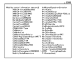
- Lists 200A to 200C in FIGS. 14 to 16 show examples of candidate lists of control signals to which CSI-RS-Config information is assigned and are repeated in space.
- candidate control signals are included in, for example, Radio resource control information information elements, Security control information elements, Mobility control information elements, Measurement information elements, Other information elements, MBMS information elements, etc. Each control signal is mentioned.
- the radio station according to the fourth embodiment selects a control signal to be repeated in the space to which the CSI-RS Config information has been allocated from the control signal candidate list, and sets the control signal in the allocation information.
- the radio station generates flag information indicating that the station is in repetition (S52).
- the radio station stores the selected control signal together with the flag information in the space where the CSI-RS Config information has been assigned (S53).
- the radio station of the fourth embodiment transmits an RRC signal (S54).
- the transmitted RRC signal is received by the radio terminal according to the fourth embodiment, and the replicated control information is acquired based on the flag information.
- the fourth embodiment it is possible to improve transmission control characteristics in a wireless communication system that performs CoMP communication. Furthermore, the reliability of other control signals can be improved by repeating and transmitting other control signals using the RRC signal of the higher layer control information.
- transmission is performed at a later timing than the CSI-RS Config information to the space allocated to the CSI-RS Config information in the space where the radio resource information of the upper layer control information is stored.
- a control signal to be transmitted may be assigned and transmitted.
- a list 210 of FIG. 17 shows an example of a candidate list of control signals transmitted at a timing after the CSI-RS Config information.
- the scheduler 122 selects a control signal to be allocated to the space to which the CSI-RS Config information has been allocated from the control signal candidate list transmitted at a timing later than the CSI-RS Config information, and assigns it to the allocation information. Set.
- the allocation / arrangement unit 128 allocates the selected control signal based on the allocation information, and transmits the selected control signal in the space where the CSI-RS ⁇ Config information has been allocated.
- the allocation / arrangement unit 128 allocates the selected control signal based on the allocation information, and transmits the selected control signal in the space where the CSI-RS ⁇ Config information has been allocated.
- this makes it possible to advance the transmission timing of the selected control signal.
- the wireless communication systems of the first to fourth embodiments can be realized as, for example, an LTE-A system.
- the present invention can also be applied to a wireless communication system using a communication method other than LTE-A.
- the first to fourth embodiments can be applied to mobile terminals such as mobile phones, smartphones, and PDAs (Personal Digital Assistants) as wireless terminals.
- the first to fourth embodiments can be applied to various communication devices that communicate with a base station such as a mobile relay station.
- first to fourth embodiments can be applied to base stations of various scales such as macro base stations and femto base stations as radio stations.
- first to fourth embodiments can be applied to various communication devices that communicate with mobile stations such as relay stations.
- each component of the radio station and radio terminal is not limited to the mode of the first to fourth embodiments, and all or a part thereof can be used for various loads, usage conditions, etc. Accordingly, it may be configured to be functionally or physically distributed / integrated in an arbitrary unit.
- the memory may be connected via a network or a cable as an external device of a wireless station or a wireless terminal.
Landscapes
- Engineering & Computer Science (AREA)
- Computer Networks & Wireless Communication (AREA)
- Signal Processing (AREA)
- Mobile Radio Communication Systems (AREA)
Abstract
L'objectif de la présente technique, qui a été conçue en vue de ce qui précède, est de proposer un procédé de communication sans fil, un système de communication sans fil, une station radio et un terminal radio dont les caractéristiques de commande de transmission peuvent être améliorées dans une communication multipoint coordonnée. Selon un procédé de communication sans fil destiné à être utilisé dans un système de communication sans fil dans lequel une cellule unique comprend une pluralité de nœuds et qui a un terminal radio capable d'effectuer des communications coordonnées avec un ou plusieurs nœuds, la cellule informe ledit terminal radioélectrique d'informations relatives à un signal de référence de chacun des nœuds de la pluralité avant qu'un établissement de connexion au terminal radio ne soit effectué, et le terminal radio transmet un signal, qui doit être utilisé pour l'établissement de connexion, à l'aide d'un paramètre qui est conforme à la qualité de communication de chacun des nœuds de la pluralité acquise à l'aide des informations liées au signal de référence de chacun de nœuds de la pluralité.
Priority Applications (1)
| Application Number | Priority Date | Filing Date | Title |
|---|---|---|---|
| PCT/JP2012/001127 WO2013124881A1 (fr) | 2012-02-20 | 2012-02-20 | Procédé de communication sans fil, système de communication sans fil, station radio et terminal radio |
Applications Claiming Priority (1)
| Application Number | Priority Date | Filing Date | Title |
|---|---|---|---|
| PCT/JP2012/001127 WO2013124881A1 (fr) | 2012-02-20 | 2012-02-20 | Procédé de communication sans fil, système de communication sans fil, station radio et terminal radio |
Publications (1)
| Publication Number | Publication Date |
|---|---|
| WO2013124881A1 true WO2013124881A1 (fr) | 2013-08-29 |
Family
ID=49005111
Family Applications (1)
| Application Number | Title | Priority Date | Filing Date |
|---|---|---|---|
| PCT/JP2012/001127 Ceased WO2013124881A1 (fr) | 2012-02-20 | 2012-02-20 | Procédé de communication sans fil, système de communication sans fil, station radio et terminal radio |
Country Status (1)
| Country | Link |
|---|---|
| WO (1) | WO2013124881A1 (fr) |
Cited By (1)
| Publication number | Priority date | Publication date | Assignee | Title |
|---|---|---|---|---|
| JP2016538764A (ja) * | 2013-10-24 | 2016-12-08 | ホアウェイ・テクノロジーズ・カンパニー・リミテッド | アップリンク電力制御方法及び装置 |
Citations (3)
| Publication number | Priority date | Publication date | Assignee | Title |
|---|---|---|---|---|
| JP2009213057A (ja) * | 2008-03-06 | 2009-09-17 | Panasonic Corp | 無線基地局装置、無線端末装置、無線中継局装置、送信パワー制御方法、無線通信中継方法および無線通信システム |
| JP2011146804A (ja) * | 2010-01-12 | 2011-07-28 | Sumitomo Electric Ind Ltd | 基地局装置 |
| JP2011530963A (ja) * | 2008-08-11 | 2011-12-22 | クゥアルコム・インコーポレイテッド | ノードbにおいて自己調整送信電力及び感度レベルを補償する自動化されたパラメータ調整のための方法及び装置 |
-
2012
- 2012-02-20 WO PCT/JP2012/001127 patent/WO2013124881A1/fr not_active Ceased
Patent Citations (3)
| Publication number | Priority date | Publication date | Assignee | Title |
|---|---|---|---|---|
| JP2009213057A (ja) * | 2008-03-06 | 2009-09-17 | Panasonic Corp | 無線基地局装置、無線端末装置、無線中継局装置、送信パワー制御方法、無線通信中継方法および無線通信システム |
| JP2011530963A (ja) * | 2008-08-11 | 2011-12-22 | クゥアルコム・インコーポレイテッド | ノードbにおいて自己調整送信電力及び感度レベルを補償する自動化されたパラメータ調整のための方法及び装置 |
| JP2011146804A (ja) * | 2010-01-12 | 2011-07-28 | Sumitomo Electric Ind Ltd | 基地局装置 |
Non-Patent Citations (2)
| Title |
|---|
| BRUNO CLERCKX ET AL.: "Coordinated multi- point transmission in heterogeneous networks: A distributed antenna system approach", CIRCUITS AND SYSTEMS (MWSCAS), 2011 IEEE 54TH INTERNATIONAL MIDWEST SYMPOSIUM ON, 10 August 2011 (2011-08-10), XP031941570 * |
| MASAYUKI HOSHINO ET AL.: "Tutorial on Coordinated Multi-point Transmission/Reception Techniques for LTE- Advanced", RCS2011-34, TECHNICAL COMMITTEE ON RADIO COMMUNICATION SYSTEMS (RCS), 27 May 2011 (2011-05-27) * |
Cited By (2)
| Publication number | Priority date | Publication date | Assignee | Title |
|---|---|---|---|---|
| JP2016538764A (ja) * | 2013-10-24 | 2016-12-08 | ホアウェイ・テクノロジーズ・カンパニー・リミテッド | アップリンク電力制御方法及び装置 |
| US10187881B2 (en) | 2013-10-24 | 2019-01-22 | Huawei Technologies Co., Ltd. | Uplink power control method and apparatus |
Similar Documents
| Publication | Publication Date | Title |
|---|---|---|
| US10506577B2 (en) | Systems and methods for adaptive transmissions in a wireless network | |
| US10986586B2 (en) | One method for pathloss estimation | |
| US9504084B2 (en) | Method to support an asymmetric time-division duplex (TDD) configuration in a heterogeneous network (HetNet) | |
| US10506464B2 (en) | Identification of a beamformed region | |
| CN105103467B (zh) | 基于无线电条件选择传输模式 | |
| KR101644494B1 (ko) | 무선 통신 방법, 무선 통신 시스템, 무선국 및 무선 단말기 | |
| CN104521319A (zh) | 终端、基站、通信方法以及集成电路 | |
| US20150382376A1 (en) | Wireless communication method, wireless communication system, wireless station, and wireless terminal | |
| KR101472101B1 (ko) | 단말, 상향링크 채널 추정 방법 및 통신 시스템 | |
| EP4154411B1 (fr) | Procédés d'envoi d'un signal de cri d'ue dans des réseaux privés avec un spectre sous licence local | |
| WO2013140437A1 (fr) | Procédé de communication sans fil, système de communication sans fil, station sans fil et terminal sans fil | |
| WO2013124881A1 (fr) | Procédé de communication sans fil, système de communication sans fil, station radio et terminal radio | |
| JP2016105653A (ja) | 無線通信方法、無線通信システム、無線局、及び無線端末 | |
| JP5999099B2 (ja) | 無線通信システム、無線通信方法、及び無線通信装置 | |
| WO2014203298A1 (fr) | Procédé de radiocommunication, système de radiocommunication, station radio et terminal radio |
Legal Events
| Date | Code | Title | Description |
|---|---|---|---|
| 121 | Ep: the epo has been informed by wipo that ep was designated in this application |
Ref document number: 12869103 Country of ref document: EP Kind code of ref document: A1 |
|
| NENP | Non-entry into the national phase |
Ref country code: DE |
|
| 122 | Ep: pct application non-entry in european phase |
Ref document number: 12869103 Country of ref document: EP Kind code of ref document: A1 |
|
| NENP | Non-entry into the national phase |
Ref country code: JP |