WO2013125116A1 - Structure d'étanchéité - Google Patents
Structure d'étanchéité Download PDFInfo
- Publication number
- WO2013125116A1 WO2013125116A1 PCT/JP2012/080330 JP2012080330W WO2013125116A1 WO 2013125116 A1 WO2013125116 A1 WO 2013125116A1 JP 2012080330 W JP2012080330 W JP 2012080330W WO 2013125116 A1 WO2013125116 A1 WO 2013125116A1
- Authority
- WO
- WIPO (PCT)
- Prior art keywords
- annular groove
- gasket
- injector
- sealing structure
- groove
- Prior art date
- Legal status (The legal status is an assumption and is not a legal conclusion. Google has not performed a legal analysis and makes no representation as to the accuracy of the status listed.)
- Ceased
Links
Images

Classifications
-
- F—MECHANICAL ENGINEERING; LIGHTING; HEATING; WEAPONS; BLASTING
- F02—COMBUSTION ENGINES; HOT-GAS OR COMBUSTION-PRODUCT ENGINE PLANTS
- F02M—SUPPLYING COMBUSTION ENGINES IN GENERAL WITH COMBUSTIBLE MIXTURES OR CONSTITUENTS THEREOF
- F02M61/00—Fuel-injectors not provided for in groups F02M39/00 - F02M57/00 or F02M67/00
- F02M61/16—Details not provided for in, or of interest apart from, the apparatus of groups F02M61/02 - F02M61/14
-
- F—MECHANICAL ENGINEERING; LIGHTING; HEATING; WEAPONS; BLASTING
- F02—COMBUSTION ENGINES; HOT-GAS OR COMBUSTION-PRODUCT ENGINE PLANTS
- F02F—CYLINDERS, PISTONS OR CASINGS, FOR COMBUSTION ENGINES; ARRANGEMENTS OF SEALINGS IN COMBUSTION ENGINES
- F02F1/00—Cylinders; Cylinder heads
- F02F1/24—Cylinder heads
-
- F—MECHANICAL ENGINEERING; LIGHTING; HEATING; WEAPONS; BLASTING
- F02—COMBUSTION ENGINES; HOT-GAS OR COMBUSTION-PRODUCT ENGINE PLANTS
- F02F—CYLINDERS, PISTONS OR CASINGS, FOR COMBUSTION ENGINES; ARRANGEMENTS OF SEALINGS IN COMBUSTION ENGINES
- F02F11/00—Arrangements of sealings in combustion engines
-
- F—MECHANICAL ENGINEERING; LIGHTING; HEATING; WEAPONS; BLASTING
- F02—COMBUSTION ENGINES; HOT-GAS OR COMBUSTION-PRODUCT ENGINE PLANTS
- F02M—SUPPLYING COMBUSTION ENGINES IN GENERAL WITH COMBUSTIBLE MIXTURES OR CONSTITUENTS THEREOF
- F02M61/00—Fuel-injectors not provided for in groups F02M39/00 - F02M57/00 or F02M67/00
- F02M61/14—Arrangements of injectors with respect to engines; Mounting of injectors
-
- F—MECHANICAL ENGINEERING; LIGHTING; HEATING; WEAPONS; BLASTING
- F16—ENGINEERING ELEMENTS AND UNITS; GENERAL MEASURES FOR PRODUCING AND MAINTAINING EFFECTIVE FUNCTIONING OF MACHINES OR INSTALLATIONS; THERMAL INSULATION IN GENERAL
- F16J—PISTONS; CYLINDERS; SEALINGS
- F16J15/00—Sealings
- F16J15/02—Sealings between relatively-stationary surfaces
- F16J15/06—Sealings between relatively-stationary surfaces with solid packing compressed between sealing surfaces
- F16J15/10—Sealings between relatively-stationary surfaces with solid packing compressed between sealing surfaces with non-metallic packing
-
- F—MECHANICAL ENGINEERING; LIGHTING; HEATING; WEAPONS; BLASTING
- F02—COMBUSTION ENGINES; HOT-GAS OR COMBUSTION-PRODUCT ENGINE PLANTS
- F02M—SUPPLYING COMBUSTION ENGINES IN GENERAL WITH COMBUSTIBLE MIXTURES OR CONSTITUENTS THEREOF
- F02M2200/00—Details of fuel-injection apparatus, not otherwise provided for
- F02M2200/85—Mounting of fuel injection apparatus
- F02M2200/858—Mounting of fuel injection apparatus sealing arrangements between injector and engine
Definitions
- the present invention relates to a sealing structure that seals an annular gap between an injector and a housing.
- an annular gasket that seals the annular gap between the injector and the attachment hole is provided.
- the technology increases the volume of the gasket in a state where no external force is applied to the volume of the space in which the gasket is installed, and enhances the sealing performance by filling the annular groove in which the gasket is installed with the gasket. Is known (see Patent Document 1).
- An object of the present invention is to provide a sealing structure capable of reducing the built-in load while improving the sealing performance.
- the present invention employs the following means in order to solve the above problems.
- the sealing structure of the present invention is An injector, A housing having a mounting hole to which the injector is mounted; An annular gasket that is mounted in an annular groove formed on the outer periphery of the injector and seals an annular gap between the injector and the mounting hole;
- a sealing structure comprising: The annular groove has a step at the groove bottom; A main annular groove on one side through the step; A secondary annular groove on the other side through the step; With The gasket is arranged to fill the main annular groove; The gap between the injector and the mounting hole at the boundary between the main annular groove and the sub annular groove is larger than the minute gap on the opposite side of the sub annular groove through the main annular groove.
- the sealing performance can be improved.
- the sub annular groove is provided, a part of the gasket filled in the main annular groove can protrude into the sub annular groove. For this reason, it is possible to reduce an assembling load when assembling the injector equipped with the gasket into the mounting hole.
- the gap between the injector and the mounting hole at the boundary between the main annular groove and the sub-annular groove is larger than the minute gap on the opposite side of the sub-annular groove via the main annular groove. Further, a part of the gasket can be protruded to the sub annular groove side.
- the area of the cross section cut along the plane including the axis in the annular space formed by the main annular groove and the surface of the mounting hole is S1
- the axis in the annular space formed by the secondary annular groove and the surface of the mounting hole is S2
- the secondary annular groove may be arranged on the combustion chamber side with respect to the main annular groove.
- the frictional resistance against the gasket acts on the side opposite to the combustion chamber, so that the gasket can be more reliably filled into the main annular groove side. .
- part with which the sub annular groove side was filled among the gaskets receives the pressure of combustion gas, the filling state of the gasket with respect to the main annular groove can be maintained, and sealing performance can be improved.
- the filling state of the gasket with respect to the main annular groove can be stably maintained by receiving the pressure of the combustion gas, and the durability is also improved.
- the shape of the cross section cut along the plane including the axis in the gasket in a state where no external force is applied may be rectangular.
- the groove bottom of the main annular groove may have an annular protrusion near the center in the axial direction.
- the built-in load can be reduced while enhancing the sealing performance.
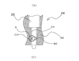
- FIG. 1 is a schematic cross-sectional view showing a sealing structure according to an embodiment of the present invention.
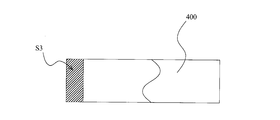
- FIG. 2 is a partially broken sectional view of the gasket according to the embodiment of the present invention.
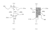
- FIG. 3 is a schematic cross-sectional view of the sealing structure according to the first embodiment of the present invention.
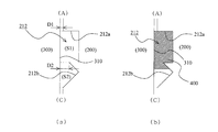
- FIG. 4 is a schematic cross-sectional view of a sealing structure according to Embodiment 2 of the present invention.
- FIG. 5 is a schematic cross-sectional view of a sealing structure according to Embodiment 3 of the present invention.
- FIG. 6 is a schematic cross-sectional view of a sealing structure according to Embodiment 4 of the present invention.
- FIG. 7 is a schematic cross-sectional view of a sealing structure according to Embodiment 5 of the present invention.
- FIG. 8 is a schematic cross-sectional view of a sealing structure according to Embodiment 6 of the present invention.
- the sealing structure 100 includes an injector 200, a housing 300 having a mounting hole 310 to which the injector 200 is attached, and a gasket 400.
- FIG. 1 only the vicinity of the tip constituting the sealing structure is shown for the injector 200.
- the housing 300 corresponds to the cylinder head of the engine, and shows only the vicinity that constitutes the sealing structure.
- the gasket 400 is an annular member made of PTFE (tetrafluoroethylene resin). Moreover, the gasket 400 is a cylindrical member, and the shape of the cross section cut
- PTFE tetrafluoroethylene resin
- Example 1 With reference to FIG. 3, the sealing structure which concerns on Example 1 of this invention is demonstrated.
- 3 is a schematic cross-sectional view of the sealing structure according to the first embodiment of the present invention, and corresponds to an enlarged view of a portion X in FIG. 3A is a diagram in which the gasket 400 is omitted, and FIG. 3B is a diagram in which the gasket 400 is also clearly shown.
- the annular groove 211 formed on the outer periphery of the injector 200 has a step at the groove bottom, and the main annular groove 211a on one side and the sub-groove on the other side through the step. And an annular groove 211b.
- the step is a step whose diameter increases from the atmosphere side (A) to the combustion chamber side (C).
- the groove bottoms of the main annular groove 211a and the sub-annular groove 211b are both cylindrical surfaces.
- the main annular groove 211a is provided on the atmosphere side (A), and the sub annular groove 211b is provided on the combustion chamber side (C).
- the gap D2 between the injector 200 and the attachment hole 310 at the boundary between the main annular groove 211a and the sub annular groove 211b is a minute gap opposite to the sub annular groove 211b via the main annular groove 211a. It is configured to be larger than D1.
- the gap D2 is smaller than the distance between the groove bottom of the main annular groove 211a and the attachment hole 310.
- the areas S1, S2 shown in FIG. 3 and the area S3 shown in FIG. 2 are configured to satisfy S1 ⁇ S3 ⁇ (S1 + S2).
- the area S ⁇ b> 1 is an area of a cross section cut along a plane including an axis in an annular space formed by the main annular groove 211 a and the surface of the attachment hole 310.
- the area S2 is an area of a cross section cut by a plane including an axis in an annular space formed by the sub annular groove 211b and the surface of the attachment hole 310.
- the area S3 is an area of a cross section cut by a plane including the axis line in the gasket 400 in a state where no external force is received.
- the injector 200 When the injector 200 is assembled into the housing 300, the injector 200 is attached to the annular groove 211 of the injector 200 with the gasket 400 attached from the atmosphere side (A) to the combustion chamber (C) side. Attach to. Thereby, in a state where no external force is received, the gasket 400 having a rectangular cross section receives a force from the inner peripheral surface of the mounting hole 310 toward the inside, and deforms along the shape of the annular groove 211. More specifically, the main annular groove 211a is (substantially) completely filled with the gasket 400, and a part of the surplus meat is filled into the sub-annular groove 211b (see FIG. 3B).
- the gasket 400 is (substantially) completely filled in the main annular groove 211a, so that the sealing performance can be improved. Further, since the sub annular groove 211b is provided, a part of the gasket 400 filled in the main annular groove 211a can protrude into the sub annular groove 211b. Thereby, the built-in load at the time of incorporating the injector 200 equipped with the gasket 400 into the mounting hole 310 can be reduced. Therefore, the built-in load can be reduced while improving the sealing performance.
- the gap D2 between the injector 200 and the attachment hole 310 at the boundary between the main annular groove 211a and the sub annular groove 211b is a minute gap on the opposite side of the sub annular groove 211b via the main annular groove 211a. Since it is larger than D1, a part of the gasket 400 can be more reliably protruded to the sub annular groove 211b side.
- the gasket 400 is (substantially) completely inserted into the main annular groove 211a. Filling can be performed, and the sub-annular groove 211b can prevent the gasket 400 from being completely filled. Therefore, the gasket 400 can be prevented from protruding outside the annular groove 211. Moreover, a built-in load can be suppressed in connection with this.
- the sub annular groove 211b is disposed on the combustion chamber (C) side with respect to the main annular groove 211a. Therefore, when the injector 200 to which the gasket 400 is mounted is assembled into the mounting hole 310, the frictional resistance against the gasket 400 acts on the side opposite to the combustion chamber (C). Therefore, the gasket 400 can be more reliably filled on the main annular groove 211a side. Moreover, since the site
- Example 2 With reference to FIG. 4, the sealing structure based on Example 2 of this invention is demonstrated.
- 4 is a schematic cross-sectional view of a sealing structure according to Embodiment 2 of the present invention, and corresponds to an enlarged view of a portion X in FIG. 4A is a diagram in which the gasket 400 is omitted, and FIG. 4B is a diagram in which the gasket 400 is also clearly shown.
- the annular groove 212 formed on the outer periphery of the injector 200 has a step at the groove bottom, and the main annular groove 212a on one side and the sub-groove on the other side through the step. And an annular groove 212b.
- the step is a step whose diameter increases from the atmosphere side (A) to the combustion chamber side (C).
- the groove bottom of the main annular groove 212a has a cylindrical surface as in the case of the first embodiment.
- the groove bottom of the sub-annular groove 212b is arranged so that the two adjacent grooves are expanded from the atmosphere side (A) toward the combustion chamber side (C) and then expanded. It consists of a tapered surface.
- the main annular groove 212a is provided on the atmosphere side (A), and the sub-annular groove 212b is provided on the combustion chamber side (C) as in the first embodiment.
- the point which is comprised so that the clearance gap D2 may become larger than the micro clearance gap D1 is the same as that of Example 1.
- FIG. The gap D2 is smaller than the distance between the groove bottom of the main annular groove 212a and the attachment hole 310. Since the definitions of D1 and D2 are as described in the first embodiment, the description thereof is omitted here.
- the area S1, S2 shown in FIG. 4 and the area S3 shown in FIG. 2 are configured to satisfy S1 ⁇ S3 ⁇ (S1 + S2).
- the gasket 400 is configured such that, in the sub annular groove 212b, the bottom surface of the groove is filled in a tapered surface portion whose diameter decreases from the atmosphere side (A) toward the combustion chamber side (C) ( (Refer FIG.4 (b)).
- the gasket 400 is filled in a portion of the sub-annular groove 212b that has a tapered surface whose diameter decreases from the atmosphere side (A) toward the combustion chamber side (C). It is comprised so that. Thereby, the area of the part which receives the pressure of combustion gas among the gaskets 400 can be made wide compared with the case of Example 1.
- the force that the gasket 400 receives in the direction of the main annular groove 212a due to the pressure of the combustion gas becomes larger than that in the case of the first embodiment, so that the filling state of the gasket 400 in the main annular groove 212a can be further maintained. Can do.
- Example 3 With reference to FIG. 5, the sealing structure which concerns on Example 3 of this invention is demonstrated.
- 5 is a schematic cross-sectional view of a sealing structure according to Embodiment 3 of the present invention, and corresponds to an enlarged view of a portion X in FIG. 5A is a diagram in which the gasket 400 is omitted, and FIG. 5B is a diagram in which the gasket 400 is also clearly shown.
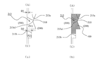
- the annular groove 213 formed on the outer periphery of the injector 200 has a step at the groove bottom, and the main annular groove 213a on one side and the sub-groove on the other side through the step. And an annular groove 213b.
- the step is a step whose diameter increases from the atmosphere side (A) to the combustion chamber side (C).
- the groove bottom of the main annular groove 213a is composed of two adjacent tapered surfaces so that the diameter is reduced after the diameter is increased from the atmosphere side (A) toward the combustion chamber side (C).
- an annular protrusion 213a1 is provided near the center in the axial direction at the groove bottom of the main annular groove 213a.
- the groove bottom of the sub-annular groove 213b is formed of a cylindrical surface as in the case of the first embodiment.
- the main annular groove 213a is provided on the atmosphere side (A) and the sub-annular groove 213b is provided on the combustion chamber side (C) as in the first embodiment.
- the point which is comprised so that the clearance gap D2 may become larger than the micro clearance gap D1 is the same as that of Example 1.
- FIG. The gap D2 is smaller than the distance (shortest distance) between the groove bottom of the main annular groove 213a and the attachment hole 310. Since the definitions of D1 and D2 are as described in the first embodiment, the description thereof is omitted here.
- the areas S1 and S2 shown in FIG. 5 and the area S3 shown in FIG. 2 are configured to satisfy S1 ⁇ S3 ⁇ (S1 + S2) as in the first embodiment.
- annular protrusion 213a1 is provided near the center in the axial direction at the groove bottom of the main annular groove 213a. Thereby, the surface pressure with respect to the attachment hole 310 of the gasket 400 can be partially made high, and sealing performance can be improved.
- Example 4 With reference to FIG. 6, the sealing structure based on Example 4 of this invention is demonstrated.
- 6 is a schematic cross-sectional view of a sealing structure according to Embodiment 4 of the present invention, and corresponds to an enlarged view of a portion X in FIG. 6A is a diagram in which the gasket 400 is omitted, and FIG. 6B is a diagram in which the gasket 400 is also clearly shown.
- the annular groove 214 formed on the outer periphery of the injector 200 has a step at the groove bottom, and the main annular groove 214a on one side and the sub-groove on the other side through the step. And an annular groove 214b.
- the step is a step whose diameter increases from the atmosphere side (A) to the combustion chamber side (C).
- the groove bottom of the main annular groove 214a has two adjacent tapered surfaces so that the diameter is increased and then reduced from the atmosphere side (A) toward the combustion chamber side (C). It consists of
- an annular protrusion 214a1 is provided near the center in the axial direction at the groove bottom of the main annular groove 214a.
- the groove bottom of the sub annular groove 214b is composed of two adjacent tapered surfaces so that the diameter is reduced after being reduced in diameter from the atmosphere side (A) toward the combustion chamber side (C).
- the main annular groove 214a is provided on the atmosphere side (A) and the sub-annular groove 214b is provided on the combustion chamber side (C) as in the first embodiment.
- the point which is comprised so that the clearance gap D2 may become larger than the micro clearance gap D1 is the same as that of Example 1.
- FIG. The gap D2 is smaller than the distance (shortest distance) between the groove bottom of the main annular groove 214a and the attachment hole 310. Since the definitions of D1 and D2 are as described in the first embodiment, the description thereof is omitted here.
- the areas S1 and S2 shown in FIG. 6 and the area S3 shown in FIG. 2 are configured to satisfy S1 ⁇ S3 ⁇ (S1 + S2) as in the first embodiment.
- the gasket 400 is configured so that, in the sub-annular groove 214b, the bottom surface of the groove is filled in a tapered surface portion whose diameter is reduced from the atmosphere side (A) toward the combustion chamber side (C) ( (Refer FIG.6 (b)).
- the gasket 400 is filled in a tapered surface portion of the sub-annular groove 214b whose bottom surface is reduced in diameter from the atmosphere side (A) toward the combustion chamber side (C). It is comprised so that. Thereby, the area of the part which receives the pressure of combustion gas among the gaskets 400 can be made wide compared with the case of Example 1.
- the force that the gasket 400 receives in the direction of the main annular groove 214a due to the pressure of the combustion gas is larger than that in the case of the first embodiment, so that the filling state of the gasket 400 in the main annular groove 214a can be further maintained.
- an annular protrusion 214a1 is provided near the center in the axial direction at the groove bottom of the main annular groove 214a.
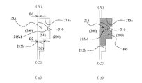
- Example 5 With reference to FIG. 7, the sealing structure based on Example 5 of this invention is demonstrated.
- 7 is a schematic cross-sectional view of a sealing structure according to Embodiment 5 of the present invention, and corresponds to an enlarged view of a portion X in FIG. 7A is a diagram in which the gasket 400 is omitted, and FIG. 7B is a diagram in which the gasket 400 is also clearly shown.
- the annular groove 215 formed on the outer periphery of the injector 200 has a step at the groove bottom, and the main annular groove 215a on one side and the sub-groove on the other side through the step. And an annular groove 215b.
- the step is a step whose diameter increases from the atmosphere side (A) to the combustion chamber side (C).
- the groove bottom of the main annular groove 215a is generally formed of a cylindrical surface, an annular protrusion 215a1 is provided near the center in the axial direction.
- the groove bottom of the sub-annular groove 215b is formed of a cylindrical surface as in the case of the first embodiment.
- the main annular groove 215a is provided on the atmosphere side (A) and the sub-annular groove 215b is provided on the combustion chamber side (C) as in the first embodiment.
- the point which is comprised so that the clearance gap D2 may become larger than the micro clearance gap D1 is the same as that of Example 1.
- FIG. The gap D2 is smaller than the distance (shortest distance) between the groove bottom of the main annular groove 215a and the attachment hole 310. Since the definitions of D1 and D2 are as described in the first embodiment, the description thereof is omitted here.
- the areas S1 and S2 shown in FIG. 7 and the area S3 shown in FIG. 2 are configured to satisfy S1 ⁇ S3 ⁇ (S1 + S2) as in the first embodiment.
- an annular protrusion 215a1 is provided near the center in the axial direction at the groove bottom of the main annular groove 215a. Thereby, the surface pressure with respect to the attachment hole 310 of the gasket 400 can be partially made high, and sealing performance can be improved.
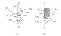
- FIG. 8 is a schematic cross-sectional view of a sealing structure according to Embodiment 6 of the present invention, and corresponds to an enlarged view of a portion X in FIG. 8A is a diagram in which the gasket 400 is omitted, and FIG. 8B is a diagram in which the gasket 400 is also clearly shown.
- the annular groove 216 formed on the outer periphery of the injector 200 has a step at the groove bottom, and the main annular groove 216a on one side and the sub-groove on the other side through the step. And an annular groove 216b.
- the step is a step whose diameter increases from the atmosphere side (A) to the combustion chamber side (C).
- the groove bottom of the main annular groove 216a is generally formed of a cylindrical surface, an annular protrusion 216a1 is provided near the center in the axial direction.
- the groove bottom of the sub-annular groove 216b is composed of two adjacent tapered surfaces so that the diameter of the groove decreases from the atmosphere side (A) toward the combustion chamber side (C) and then increases.
- the main annular groove 216a is provided on the atmosphere side (A) and the sub-annular groove 216b is provided on the combustion chamber side (C) as in the first embodiment.
- the point which is comprised so that the clearance gap D2 may become larger than the micro clearance gap D1 is the same as that of Example 1.
- FIG. The gap D2 is smaller than the distance (shortest distance) between the groove bottom of the main annular groove 216a and the attachment hole 310. Since the definitions of D1 and D2 are as described in the first embodiment, the description thereof is omitted here. 8 is the same as the first embodiment in that the areas S1 and S2 shown in FIG. 8 and the area S3 shown in FIG. 2 are configured to satisfy S1 ⁇ S3 ⁇ (S1 + S2).
- the gasket 400 is configured such that, in the sub-annular groove 216b, the bottom surface of the groove is filled in a tapered surface portion whose diameter is reduced from the atmosphere side (A) toward the combustion chamber side (C) ( (Refer FIG.8 (b)).
- the gasket 400 is filled in a portion of the sub-annular groove 216b that has a tapered surface whose diameter decreases from the atmosphere side (A) to the combustion chamber side (C). It is comprised so that. Thereby, the area of the part which receives the pressure of combustion gas among the gaskets 400 can be made wide compared with the case of Example 1.
- an annular protrusion 216a1 is provided near the center in the axial direction at the groove bottom of the main annular groove 216a. Thereby, the surface pressure with respect to the attachment hole 310 of the gasket 400 can be partially made high, and sealing performance can be improved.
Landscapes
- Engineering & Computer Science (AREA)
- General Engineering & Computer Science (AREA)
- Mechanical Engineering (AREA)
- Chemical & Material Sciences (AREA)
- Combustion & Propulsion (AREA)
- Gasket Seals (AREA)
- Fuel-Injection Apparatus (AREA)
- Jet Pumps And Other Pumps (AREA)
Priority Applications (4)
| Application Number | Priority Date | Filing Date | Title |
|---|---|---|---|
| KR1020147022754A KR20140105619A (ko) | 2012-02-24 | 2012-11-22 | 밀봉구조 |
| CN201280070194.1A CN104136762B (zh) | 2012-02-24 | 2012-11-22 | 密封结构 |
| US14/379,928 US20150035237A1 (en) | 2012-02-24 | 2012-11-22 | Sealing structure |
| EP12869461.9A EP2818688A4 (fr) | 2012-02-24 | 2012-11-22 | Structure d'étanchéité |
Applications Claiming Priority (2)
| Application Number | Priority Date | Filing Date | Title |
|---|---|---|---|
| JP2012-038641 | 2012-02-24 | ||
| JP2012038641A JP5867158B2 (ja) | 2012-02-24 | 2012-02-24 | 密封構造 |
Publications (1)
| Publication Number | Publication Date |
|---|---|
| WO2013125116A1 true WO2013125116A1 (fr) | 2013-08-29 |
Family
ID=49005316
Family Applications (1)
| Application Number | Title | Priority Date | Filing Date |
|---|---|---|---|
| PCT/JP2012/080330 Ceased WO2013125116A1 (fr) | 2012-02-24 | 2012-11-22 | Structure d'étanchéité |
Country Status (6)
| Country | Link |
|---|---|
| US (1) | US20150035237A1 (fr) |
| EP (1) | EP2818688A4 (fr) |
| JP (1) | JP5867158B2 (fr) |
| KR (1) | KR20140105619A (fr) |
| CN (1) | CN104136762B (fr) |
| WO (1) | WO2013125116A1 (fr) |
Families Citing this family (6)
| Publication number | Priority date | Publication date | Assignee | Title |
|---|---|---|---|---|
| CN106321826A (zh) * | 2015-06-17 | 2017-01-11 | 镇江市中能机械设备有限公司 | T型垫圈 |
| CN106640405B (zh) * | 2016-12-28 | 2020-05-15 | 沪东重机有限公司 | 一种低速柴油机填料函内部密封环结构 |
| JP6806037B2 (ja) * | 2017-11-13 | 2021-01-06 | トヨタ自動車株式会社 | インジェクタの取付構造 |
| DE102017221203A1 (de) | 2017-11-27 | 2019-05-29 | Hyundai Motor Company | Kraftstoffeinspritzsystem und Verfahren zum Betreiben eines Kraftstoffeinspritzsystems |
| JP7580231B2 (ja) * | 2020-09-16 | 2024-11-11 | Nok株式会社 | 密封構造及び密封構造の組立方法 |
| JP7296528B2 (ja) * | 2020-11-20 | 2023-06-22 | Nok株式会社 | 密封構造及び密封構造の組立方法 |
Citations (8)
| Publication number | Priority date | Publication date | Assignee | Title |
|---|---|---|---|---|
| JPS61117958U (fr) * | 1985-01-09 | 1986-07-25 | ||
| JPH04131570A (ja) * | 1990-09-25 | 1992-05-06 | Fuji Electric Co Ltd | 密封装置 |
| JPH1113593A (ja) * | 1997-06-11 | 1999-01-19 | Caterpillar Inc | インジェクターの燃焼ガスシール |
| JP2002081542A (ja) * | 2000-09-04 | 2002-03-22 | Honda Motor Co Ltd | シール装置 |
| JP2002081548A (ja) | 2000-09-04 | 2002-03-22 | Honda Motor Co Ltd | シール構造 |
| JP2003536019A (ja) * | 2000-06-03 | 2003-12-02 | ローベルト ボツシユ ゲゼルシヤフト ミツト ベシユレンクテル ハフツング | 燃料噴射弁に用いられるシール装置および押え |
| JP2004506135A (ja) * | 2000-08-05 | 2004-02-26 | ローベルト ボツシユ ゲゼルシヤフト ミツト ベシユレンクテル ハフツング | 燃料噴射弁 |
| JP2005226517A (ja) * | 2004-02-12 | 2005-08-25 | Nok Corp | シール構造 |
Family Cites Families (13)
| Publication number | Priority date | Publication date | Assignee | Title |
|---|---|---|---|---|
| US4579354A (en) * | 1984-12-05 | 1986-04-01 | Vassallo Research And Development Corporation | Gasket |
| US4938193A (en) * | 1987-06-15 | 1990-07-03 | Stanadyne Automotive Corp. | Fuel injection nozzle |
| US5219189A (en) * | 1989-12-11 | 1993-06-15 | Pont-A-Mousson S.A. | Composite gasket for the locked assembly of spigot and socket pipes |
| DE4413863C2 (de) * | 1994-04-21 | 1996-03-28 | Parker Praedifa Gmbh | Dichtungsanordnung für Einspritzventile an Kraftstoffzuleitungen |
| US6009856A (en) * | 1998-05-27 | 2000-01-04 | Caterpillar Inc. | Fuel injector isolation |
| US6457718B1 (en) * | 2000-08-25 | 2002-10-01 | S & B Technical Products, Inc. | Method of forming a pipe joint between metal pipes using an extensible gasket |
| JP2002089412A (ja) * | 2000-09-08 | 2002-03-27 | Toyota Motor Corp | インジェクタの取付構造 |
| US6938901B2 (en) * | 2000-12-26 | 2005-09-06 | Toyota Jidosha Kabushiki Kaisha | Combustion gas seal for injector and sealing structure with the combustion gas seal |
| JP3746214B2 (ja) * | 2001-09-10 | 2006-02-15 | 大電株式会社 | 塞栓構造 |
| US7140618B2 (en) * | 2003-01-16 | 2006-11-28 | Vassallo Research & Development Corporation | Socket with dual-functional composite gasket |
| JP4267433B2 (ja) * | 2003-11-25 | 2009-05-27 | トヨタ自動車株式会社 | 燃料噴射弁用燃焼ガスシール |
| JP2007162678A (ja) * | 2005-11-16 | 2007-06-28 | Toyota Motor Corp | 燃料噴射弁 |
| FR2908171B1 (fr) * | 2006-11-02 | 2009-01-09 | Bosch Gmbh Robert | Frein a disque |
-
2012
- 2012-02-24 JP JP2012038641A patent/JP5867158B2/ja not_active Expired - Fee Related
- 2012-11-22 CN CN201280070194.1A patent/CN104136762B/zh not_active Expired - Fee Related
- 2012-11-22 KR KR1020147022754A patent/KR20140105619A/ko not_active Ceased
- 2012-11-22 US US14/379,928 patent/US20150035237A1/en not_active Abandoned
- 2012-11-22 EP EP12869461.9A patent/EP2818688A4/fr not_active Withdrawn
- 2012-11-22 WO PCT/JP2012/080330 patent/WO2013125116A1/fr not_active Ceased
Patent Citations (8)
| Publication number | Priority date | Publication date | Assignee | Title |
|---|---|---|---|---|
| JPS61117958U (fr) * | 1985-01-09 | 1986-07-25 | ||
| JPH04131570A (ja) * | 1990-09-25 | 1992-05-06 | Fuji Electric Co Ltd | 密封装置 |
| JPH1113593A (ja) * | 1997-06-11 | 1999-01-19 | Caterpillar Inc | インジェクターの燃焼ガスシール |
| JP2003536019A (ja) * | 2000-06-03 | 2003-12-02 | ローベルト ボツシユ ゲゼルシヤフト ミツト ベシユレンクテル ハフツング | 燃料噴射弁に用いられるシール装置および押え |
| JP2004506135A (ja) * | 2000-08-05 | 2004-02-26 | ローベルト ボツシユ ゲゼルシヤフト ミツト ベシユレンクテル ハフツング | 燃料噴射弁 |
| JP2002081542A (ja) * | 2000-09-04 | 2002-03-22 | Honda Motor Co Ltd | シール装置 |
| JP2002081548A (ja) | 2000-09-04 | 2002-03-22 | Honda Motor Co Ltd | シール構造 |
| JP2005226517A (ja) * | 2004-02-12 | 2005-08-25 | Nok Corp | シール構造 |
Non-Patent Citations (1)
| Title |
|---|
| See also references of EP2818688A4 * |
Also Published As
| Publication number | Publication date |
|---|---|
| KR20140105619A (ko) | 2014-09-01 |
| JP2013174287A (ja) | 2013-09-05 |
| CN104136762A (zh) | 2014-11-05 |
| EP2818688A1 (fr) | 2014-12-31 |
| CN104136762B (zh) | 2016-10-19 |
| US20150035237A1 (en) | 2015-02-05 |
| EP2818688A4 (fr) | 2015-10-21 |
| JP5867158B2 (ja) | 2016-02-24 |
Similar Documents
| Publication | Publication Date | Title |
|---|---|---|
| JP5692504B2 (ja) | ガスケット | |
| JP5867158B2 (ja) | 密封構造 | |
| KR102354320B1 (ko) | 밀봉 장치 | |
| KR20130095302A (ko) | 개스킷 | |
| WO2008069234A1 (fr) | Système d'emballage et de scellage | |
| JP5636613B2 (ja) | 流体圧機器 | |
| JP2017150674A (ja) | シールリング | |
| EP2837857A1 (fr) | Bague d'étanchéité | |
| WO2012161258A1 (fr) | Structure d'étanchéité | |
| JP5939464B2 (ja) | アブソーバ用シール | |
| JP2017519166A (ja) | 圧縮リミッタおよびフルビード荷重を有するシリンダヘッドガスケット | |
| JP6036982B2 (ja) | 密封構造 | |
| JP2002202030A (ja) | インジェクター用燃焼ガスシール | |
| WO2018034112A1 (fr) | Segment de piston | |
| CN110603395B (zh) | 机械密封 | |
| JP4853633B2 (ja) | 密封装置 | |
| WO2016143397A1 (fr) | Dispositif d'étanchéité | |
| JP6534550B2 (ja) | バルブステムシール | |
| JP6896924B2 (ja) | アキュムレータ | |
| JP2012215188A (ja) | 密封構造 | |
| JP2015068361A (ja) | ピストンリング | |
| JP2010065810A (ja) | 密封構造 | |
| JP2018132102A (ja) | ピストンリング | |
| JP2006037737A (ja) | ピストン式内燃機関 | |
| JP5195987B2 (ja) | シーリングシステム |
Legal Events
| Date | Code | Title | Description |
|---|---|---|---|
| 121 | Ep: the epo has been informed by wipo that ep was designated in this application |
Ref document number: 12869461 Country of ref document: EP Kind code of ref document: A1 |
|
| ENP | Entry into the national phase |
Ref document number: 20147022754 Country of ref document: KR Kind code of ref document: A |
|
| WWE | Wipo information: entry into national phase |
Ref document number: 14379928 Country of ref document: US |
|
| NENP | Non-entry into the national phase |
Ref country code: DE |
|
| REEP | Request for entry into the european phase |
Ref document number: 2012869461 Country of ref document: EP |
|
| WWE | Wipo information: entry into national phase |
Ref document number: 2012869461 Country of ref document: EP |