WO2013125532A1 - Embrayage électromagnétique - Google Patents
Embrayage électromagnétique Download PDFInfo
- Publication number
- WO2013125532A1 WO2013125532A1 PCT/JP2013/054025 JP2013054025W WO2013125532A1 WO 2013125532 A1 WO2013125532 A1 WO 2013125532A1 JP 2013054025 W JP2013054025 W JP 2013054025W WO 2013125532 A1 WO2013125532 A1 WO 2013125532A1
- Authority
- WO
- WIPO (PCT)
- Prior art keywords
- armature
- rotor
- armature plate
- plate
- intermediate layer
- Prior art date
- Legal status (The legal status is an assumption and is not a legal conclusion. Google has not performed a legal analysis and makes no representation as to the accuracy of the status listed.)
- Ceased
Links
Images


Classifications
-
- F—MECHANICAL ENGINEERING; LIGHTING; HEATING; WEAPONS; BLASTING
- F16—ENGINEERING ELEMENTS AND UNITS; GENERAL MEASURES FOR PRODUCING AND MAINTAINING EFFECTIVE FUNCTIONING OF MACHINES OR INSTALLATIONS; THERMAL INSULATION IN GENERAL
- F16D—COUPLINGS FOR TRANSMITTING ROTATION; CLUTCHES; BRAKES
- F16D27/00—Magnetically- or electrically- actuated clutches; Control or electric circuits therefor
- F16D27/02—Magnetically- or electrically- actuated clutches; Control or electric circuits therefor with electromagnets incorporated in the clutch, i.e. with collecting rings
- F16D27/04—Magnetically- or electrically- actuated clutches; Control or electric circuits therefor with electromagnets incorporated in the clutch, i.e. with collecting rings with axially-movable friction surfaces
- F16D27/06—Magnetically- or electrically- actuated clutches; Control or electric circuits therefor with electromagnets incorporated in the clutch, i.e. with collecting rings with axially-movable friction surfaces with friction surfaces arranged within the flux
-
- F—MECHANICAL ENGINEERING; LIGHTING; HEATING; WEAPONS; BLASTING
- F16—ENGINEERING ELEMENTS AND UNITS; GENERAL MEASURES FOR PRODUCING AND MAINTAINING EFFECTIVE FUNCTIONING OF MACHINES OR INSTALLATIONS; THERMAL INSULATION IN GENERAL
- F16D—COUPLINGS FOR TRANSMITTING ROTATION; CLUTCHES; BRAKES
- F16D13/00—Friction clutches
- F16D13/22—Friction clutches with axially-movable clutching members
- F16D13/38—Friction clutches with axially-movable clutching members with flat clutching surfaces, e.g. discs
- F16D13/40—Friction clutches with axially-movable clutching members with flat clutching surfaces, e.g. discs in which the or each axially-movable member is pressed exclusively against an axially-located member
-
- F—MECHANICAL ENGINEERING; LIGHTING; HEATING; WEAPONS; BLASTING
- F16—ENGINEERING ELEMENTS AND UNITS; GENERAL MEASURES FOR PRODUCING AND MAINTAINING EFFECTIVE FUNCTIONING OF MACHINES OR INSTALLATIONS; THERMAL INSULATION IN GENERAL
- F16D—COUPLINGS FOR TRANSMITTING ROTATION; CLUTCHES; BRAKES
- F16D27/00—Magnetically- or electrically- actuated clutches; Control or electric circuits therefor
- F16D27/10—Magnetically- or electrically- actuated clutches; Control or electric circuits therefor with an electromagnet not rotating with a clutching member, i.e. without collecting rings
- F16D27/108—Magnetically- or electrically- actuated clutches; Control or electric circuits therefor with an electromagnet not rotating with a clutching member, i.e. without collecting rings with axially movable clutching members
- F16D27/112—Magnetically- or electrically- actuated clutches; Control or electric circuits therefor with an electromagnet not rotating with a clutching member, i.e. without collecting rings with axially movable clutching members with flat friction surfaces, e.g. discs
-
- F—MECHANICAL ENGINEERING; LIGHTING; HEATING; WEAPONS; BLASTING
- F16—ENGINEERING ELEMENTS AND UNITS; GENERAL MEASURES FOR PRODUCING AND MAINTAINING EFFECTIVE FUNCTIONING OF MACHINES OR INSTALLATIONS; THERMAL INSULATION IN GENERAL
- F16D—COUPLINGS FOR TRANSMITTING ROTATION; CLUTCHES; BRAKES
- F16D27/00—Magnetically- or electrically- actuated clutches; Control or electric circuits therefor
- F16D2027/008—Details relating to the magnetic circuit, or to the shape of the clutch parts to achieve a certain magnetic path
Definitions
- the present invention relates to an electromagnetic clutch used in a compressor or the like, and more particularly, to an electromagnetic clutch in which an armature has a laminated structure of armature plates to improve a suction force to a rotor armature by excitation of an electromagnetic coil.
- the magnetic circuit formed when the armature is attracted by the excitation of the electromagnetic coil (that is, when the rotor and the armature are separated before being attracted) is formed on the armature. I had to pass between the slits.
- a magnetic circuit with a slit has a larger magnetic resistance than a magnetic circuit without a slit, and therefore the attractive force to the rotor armature by excitation of the electromagnetic coil is reduced.
- a problem to be solved by the present invention that addresses such problems is to provide an electromagnetic clutch in which the attractive force against the armature of the rotor is improved by excitation of the electromagnetic coil.
- an electromagnetic clutch includes a rotor having a built-in electromagnetic coil, and an armature disposed opposite to the rotor and attracted to the rotor by the magnetic force of the electromagnetic coil.
- the rotor is provided with a plurality of concentric slits on a contact surface with the armature, and the armature is a concentric one facing the contact surface between adjacent slits of the rotor.
- a magnetic circuit is formed from the rotor back to the rotor through the first armature plate, the intermediate layer, the second armature plate, the intermediate layer, and the first armature plate when the rotor is not in contact with the rotor.
- the contact between the rotor and the armature Sometimes, a magnetic circuit is formed from the rotor to the first armature plate, a portion between adjacent slits of the rotor, and the first armature plate to return to the rotor.
- a magnetic circuit is formed that returns from the rotor to the rotor through the first armature plate, the intermediate layer, the second armature plate, the intermediate layer, and the first armature plate.
- the magnetic circuit without passing through the slits of the first armature plate having a large magnetic resistance, since through the low reluctance second armature plate, the magnetic resistance of the entire magnetic path M 1 decreases. Therefore, the electromagnetic clutch according to the present invention can improve the attractive force to the armature of the rotor by the excitation of the electromagnetic coil.
- FIG. 1 is an exploded perspective view showing a first embodiment of an electromagnetic clutch according to the present invention. It is a center sectional view showing the electromagnetic clutch. It is a top view which decomposes
- This electromagnetic clutch is a double flux type electromagnetic clutch used for a compressor for automobiles or indoor air conditioning, and is provided in a housing of the compressor or the like. As shown in FIG. 1, the electromagnetic clutch includes a rotor 1 and an armature 2 and is connected by contact between the rotor 1 and the armature 2, and transmits power from a power source to drive the compressor.
- the double flux is a magnetic circuit (hereinafter referred to as “magnetic path”) formed at the time of contact between the rotor 1 and the armature 2 by dividing the contact surfaces of the rotor 1 and the armature 2 in the radial direction by slits. , Which means two reciprocations between the rotor 1 and the armature 2.
- magnetic path formed at the time of contact between the rotor 1 and the armature 2 reciprocates between the rotor 1 and the armature 2 three times.
- the rotor 1 has an annular shape with an open center, and is integrally formed with a pulley 12 that transmits power from a power source (not shown) such as an engine.
- a drive shaft (not shown) connected to the armature 1 is inserted into the opening 11 formed in the center. This drive shaft is supported by a radial bearing or the like between the opening 11 and the wall surface.
- the pulley 12 forms the outer periphery of the rotor 1 and is connected to the power source by a belt to rotate the rotor 1.
- a slit 14 is formed on a surface (hereinafter referred to as “contact surface”) 13 that contacts the armature 2 among the surfaces of the rotor 1.
- Two slits 14 are formed concentrically on the contact surface 13 and divide the contact surface 13 into three in the radial direction.
- the contact surface 13 divided into three by the slit 14 is connected by a connection portion 15 formed concentrically with the slit 14.
- an electromagnetic coil 16 is built in the rotor 1.
- a plurality of electromagnetic coils 16 are arranged on the same circumference, and are excited by energization to generate magnetic flux.
- the generated magnetic flux forms a magnetic path that minimizes the overall magnetic resistance.
- the magnetic resistance is represented by a ratio of magnetomotive force to magnetic flux (magnetomotive force / magnetic flux) in the magnetic path.
- the armature 2 is disposed to face the rotor 1 and includes a first armature plate 21, an intermediate layer 22, and a second armature plate 23.
- the armature 2 is formed by laminating the first armature plate 21, the intermediate layer 22, and the second armature plate 23 in this order from the rotor 1 side.
- Each of the armature plates 21 and 23 is made of a magnetic material such as iron or iron oxide.
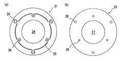
- the first armature plate 21 is disposed to face the rotor 1 and is formed in a disc shape having a circular opening 24 at the center, as shown in FIG.
- the first armature plate 21 is provided with one slit 25 and a plurality of rivet holes 26.
- the slit 25 is formed in a substantially circular shape having the same central axis as the two slits 14 formed in the rotor 1. As shown in FIG. 2, the two slits 25 of the rotor 1 are out of the contact surfaces 13 of the rotor 1. It arrange
- the two slits 14 of the rotor 1 and the slit 25 of the first armature plate 21 are formed concentrically with different radii, and the radius of the slit 25 of the first armature plate 21 is equal to the two slits of the rotor 1.
- 14 is set larger than the radius of the smaller slit 14 and smaller than the radius of the larger slit 14.
- a second armature plate 23 is provided on the opposite side of the first armature plate 21 from the rotor 1 (hereinafter referred to as “rear side”). As shown in FIG. 3B, the second armature plate 23 is formed in a disk shape having a circular opening 27 and a plurality of rivet holes 28 at the center. The opening 27 of the second armature plate 23 and the opening 24 of the first armature plate 21 are formed in a circle having the same central axis and substantially the same radius.
- An intermediate layer 22 is provided between the first armature plate 21 and the first armature plate 23.
- the intermediate layer 22 is formed of a coating film such as an anticorrosive agent applied to the surface of each armature plate 21, 23.
- a material having a lower magnetic permeability than the armature plates 21 and 23 is selected for the coating film.
- the magnetic resistance of the intermediate layer 22 becomes larger than the magnetic resistance of the armature plates 21 and 23.
- the magnetic resistance of the intermediate layer 22 is set to be smaller than the magnetic resistance of the slit 25 (that is, the space in the slit 25) of the first armature plate 21.
- the magnetic resistance of the intermediate layer 22 is set by changing the material and thickness of the coating film.
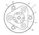
- a damping plate 29 is disposed on the back side of the second armature plate 23.
- the damping plate 29 is a substantially triangular metal member having an opening at the center, and attenuates the vibration of the armature 2.
- the damping plate 29 is connected to the first armature plate 21, the intermediate layer 22, and the second armature plate 23 by a rivet 30 that passes through the rivet hole 26 of the first armature plate 21 and the rivet hole 28 of the second armature plate 23. Is done.
- a leaf spring 31 is disposed between the second armature plate 23 and the damping plate 29.
- the leaf spring 31 is an urging means that urges the armature 2 in a direction in which the armature 2 is attracted to the damping plate 29 (that is, a direction in which the armature 2 is separated from the rotor 1).
- the armature 2 is separated from the rotor 2 by the urging force of the leaf spring 31. Therefore, the armature 2 is attracted and attracted by the electromagnetic coil 16 against the urging force of the leaf spring 31.
- a spacer 32 is arranged between the second armature plate 23 and the damping plate 29 in order to maintain a gap for arranging the leaf spring 31.
- the outer end of the leaf spring 31 is connected to the first armature by a rivet 30 (see FIG. 2) through which the rivet hole 26 of the first armature plate 21 and the rivet hole 28 of the second armature plate 23 shown in FIG. It is connected to the plate 21, the intermediate layer 22 and the second armature plate 23.
- a coupler 33 is arranged on the back side of the damping plate 29.
- the coupler 33 has a shape in which a central portion of a disk-shaped metal member protrudes toward the rotor 1, and connects the armature 2 and the drive shaft of the compressor.
- a sleeve 34 formed at the center of the coupler 33 protrudes toward the rotor 1 through the opening 27 of the second armature plate 23 and the opening 24 of the first armature plate 21.
- the coupler 33, the damping plate 29, and the inner end of the leaf spring 31 are connected by a bolt 36.
- the electromagnetic clutch in this embodiment when the electromagnetic coil 16 is not excited, the rotor 1 and the armature 2 are separated from each other by the urging force of the leaf spring 31 and the rotor 1 and the armature 2 are not in contact with each other. .
- non-contact when the rotor 1 and the armature 2 are in non-contact (hereinafter simply referred to as “non-contact”) and the electromagnetic coil 16 is excited by energization, a magnetic path M 1 is formed.
- the magnetic path M 1 passes from the rotor 1 to the rotor 1 through the first armature plate 21, the intermediate layer 22, the second armature plate 23, the intermediate layer 22, and the first armature plate 21.
- the magnetic permeability of the intermediate layer 22 is lower than the magnetic permeability of each armature plate 21, 23, but the magnetic resistance of the intermediate layer 22 is the magnetic resistance of the slit 21 (that is, the space in the slit 25) of the first armature plate 21. since it is set lower, at the time of non-contact, magnetic resistance of the magnetic path M 1 is minimized.
- the armature 2 When the magnetic path M 1 is formed, the armature 2 is attracted to the rotor 1 by the magnetic force, the rotor 1 and the armature 2 come into contact with each other, and the armature 2 is attracted to the rotor 1.
- the rotor 1 and the armature 2 are in contact (hereinafter simply referred to as “in contact”), a magnetic path M 2 is formed.
- the magnetic path M 2 passes from the rotor 1 to the rotor 1 through the first armature plate 21, the contact surface 13 a between the two slits 14 of the rotor 1, and the first armature plate 21.
- the closed circuit returns.
- the magnetic lines of force that have entered the first armature plate 21 from the rotor 1 do not pass through the intermediate layer 22 having a lower magnetic permeability than the first armature plate 21, but from the contact surface 13 a between the two slits 14 of the rotor 1.
- the rotor 1 having a higher magnetic permeability is entered.
- the magnetic lines of force that have entered the rotor 1 bypass the slit 25 of the first armature plate 21 and enter the first armature plate 21 again.
- the magnetic field lines that have entered the first armature plate 21 again enter the rotor 1 again from the contact surface 13 between the rotor 1 and the armature 2 to form a magnetic path M2. That is, the magnetic path M 2 is between the rotor 1 and the first armature plate 21, reciprocates twice while bypassing the slit 25 of the slit 14 and the first armature plate 21 of the rotor 1.
- the electromagnetic clutch according to the present embodiment includes a rotor 1 in which an electromagnetic coil 16 is built, and an armature 2 that is disposed to face the rotor 1 and is attracted and attracted to the rotor 1 by the magnetic force of the electromagnetic coil 16. Further, the rotor 1 includes two concentric slits 14 on the contact surface 13 with the armature 2, and the armature 2 is concentric 1 facing the contact surface 13 a between the adjacent slits 14 of the rotor 1.
- a first armature plate 21 having a slit 25, a second armature plate 23 provided on the back side of the first armature plate 21, and a first armature plate 21 and a second armature plate 23.
- this electromagnetic clutch when the rotor 1 and the armature 2 are not in contact with each other due to the excitation of the electromagnetic coil 16, the rotor 1 to the first armature plate 21, the intermediate layer 22, the second armature plate 23, the intermediate layer 22, the first A magnetic path M 1 returning to the rotor 1 through the armature plate 21 is formed, and when the rotor 1 and the armature 2 are in contact, the contact surface between the rotor 1 and the first armature plate 21 and the adjacent slit 14 of the rotor 1. 13a, the magnetic path M 2 is formed back to the rotor 1 through the first armature plate 21.
- the magnetic path M 1 formed during non-contact without passing through the slit 25 of the first armature plate 21 of the magnetoresistive large, through the small reluctance second armature plate 23, the magnetic path The magnetic resistance of M 1 as a whole is reduced. Therefore, the attractive force with respect to the armature 2 of the rotor 1 by excitation of the electromagnetic coil 16 can be improved.
- the magnetic path M 2 formed at the time of contact makes two reciprocations between the rotor 1 and the first armature plate 21. Therefore, the attracting force of the rotor 1 to the armature 2 by the excitation of the electromagnetic coil 16 can be improved.
- the intermediate layer 22 is formed of a coating film, it can be easily formed. Moreover, since the said coating film can use the anticorrosion agent etc. which are coated on the surface of an armature, a new material becomes unnecessary.
- a second armature plate 23 is disposed on the back side of the first armature plate 21.
- a spacer 35 is sandwiched between the armature plates 21 and 23, and a predetermined air layer (space) is maintained between the armature plates 21 and 23.
- This air layer functions as the intermediate layer 22 in the present embodiment.
- the magnetic permeability of the intermediate layer 22 is equal to the magnetic permeability of air, and thus is lower than the magnetic permeability of the armature plates 21 and 23. Therefore, the magnetic resistance of the intermediate layer 22 is larger than the magnetic resistance of the armature plates 21 and 23. Further, the magnetic resistance of the intermediate layer 22 is set to be smaller than the magnetic resistance of the slits 25 of the first armature plate 21 (that is, the space between the slits 25).
- the magnetic resistance of the intermediate layer 22 is set by changing the width of the intermediate layer (air layer) 22. In particular, the width of the intermediate layer 22 is preferably thinner than the width of the slit 25.
- the magnetic circuit M 1 at the time of non-contact as shown in FIG. 7 (a), the first armature plate 21 from the rotor 1, the intermediate layer 22, the second armature plate 23, the intermediate layer 22
- the closed circuit returns to the rotor 1 through the first armature plate 21.
- the magnetic circuit M 2 at the time of contact includes a contact surface 13 a between the rotor 1 to the first armature plate 21, the two slits 14 of the rotor 1, and the first armature plate 21. It becomes a closed circuit which returns to a rotor via.
- the intermediate layer 22 is formed by an air layer between the armature plates 21 and 23. Therefore, the intermediate layer 22 can be easily formed. Further, the magnetic resistance of the intermediate layer 22 can be easily adjusted by changing the height of the spacer 35.
- the electromagnetic clutch in this embodiment is a triple flux type. That is, the rotor 1 is provided with three concentric slits 14 on the contact surface 13 with the armature 2, and the first armature plate 21 is formed by two adjacent slits 14 among the three slits 14. Two concentric slits 25 respectively facing the two contact surfaces 13a (see FIG. 9A) are provided.
- the electromagnetic clutch according to the present embodiment, the magnetic circuit M 1 at the time of non-contact, as shown in FIG. 9 (a), the first armature plate 21 from the rotor 1, the intermediate layer 22, the second armature plate 23, the intermediate layer 22 The closed circuit returns to the rotor 1 through the first armature plate 21. Further, the magnetic circuit M 2 at the time of contact, as shown in FIG. 9 (b), while the rotor 1 of the contact surface 13a between the first armature plate 21, a slit 14 adjacent the rotor 1, the first armature A closed circuit returns to the rotor 1 through the first armature plate 21 on the other side of the plate 21 and the contact surface 13 a between the adjacent slits 14 of the rotor 1. That is, the magnetic path M 2 at the time of contact reciprocates between the rotor 1 and the armature 2 three times. With such a configuration, the attractive force of the rotor 1 to the armature 2 by the excitation of the electromagnetic coil 16 is improved.
- middle layer 22, and the 2nd armature board 23 each laminated a some plate-shaped member. It may be configured as follows.
- the second armature plate 23 may be formed by stacking two or more second armature plates 23 described in the embodiment.
- the rotor 1 may not be formed integrally with the pulley 12.
- the rotor 1 and the pulley 12 that are separately prepared may be joined by a method such as welding.
- the electromagnetic clutch is not limited to double-triple flux type
- the magnetic path M 2 at the time of contact may be configured so as to reciprocate a plurality of times of more than 4 times between the rotor 1 and the armature 2.
- N slits 14 of the rotor 1 are provided concentrically on the contact surface 13 with the armature 2.
- N ⁇ 1 slits 25 are provided concentrically so as to face N ⁇ 1 contact surfaces 13 a formed between adjacent slits 14 of the rotor 1.
- the intermediate layer 22 may be formed of a material such as soft iron or nickel having a lower magnetic permeability than the armature plates 21 and 23.
- the magnetic resistance of the intermediate layer 22 is set to be smaller than the magnetic resistance of the slits 25 of the first armature plate 21 (that is, the space between the slits 25).
- the magnetic resistance of the intermediate layer 22 can be adjusted by changing the thickness or material of the intermediate layer.
Landscapes
- Engineering & Computer Science (AREA)
- General Engineering & Computer Science (AREA)
- Mechanical Engineering (AREA)
- Physics & Mathematics (AREA)
- Electromagnetism (AREA)
- Electromagnets (AREA)
Priority Applications (3)
| Application Number | Priority Date | Filing Date | Title |
|---|---|---|---|
| DE112013001124.7T DE112013001124T5 (de) | 2012-02-23 | 2013-02-19 | elektromagnetische Kupplung |
| CN201380010716.3A CN104145129A (zh) | 2012-02-23 | 2013-02-19 | 电磁离合器 |
| US14/380,642 US20150027845A1 (en) | 2012-02-23 | 2013-02-19 | Electromagnetic Clutch |
Applications Claiming Priority (2)
| Application Number | Priority Date | Filing Date | Title |
|---|---|---|---|
| JP2012-038052 | 2012-02-23 | ||
| JP2012038052A JP2013174273A (ja) | 2012-02-23 | 2012-02-23 | 電磁クラッチ |
Publications (1)
| Publication Number | Publication Date |
|---|---|
| WO2013125532A1 true WO2013125532A1 (fr) | 2013-08-29 |
Family
ID=49005717
Family Applications (1)
| Application Number | Title | Priority Date | Filing Date |
|---|---|---|---|
| PCT/JP2013/054025 Ceased WO2013125532A1 (fr) | 2012-02-23 | 2013-02-19 | Embrayage électromagnétique |
Country Status (5)
| Country | Link |
|---|---|
| US (1) | US20150027845A1 (fr) |
| JP (1) | JP2013174273A (fr) |
| CN (1) | CN104145129A (fr) |
| DE (1) | DE112013001124T5 (fr) |
| WO (1) | WO2013125532A1 (fr) |
Families Citing this family (1)
| Publication number | Priority date | Publication date | Assignee | Title |
|---|---|---|---|---|
| CN105189146B (zh) * | 2013-05-13 | 2017-09-22 | 住友橡胶工业株式会社 | 充气轮胎 |
Citations (4)
| Publication number | Priority date | Publication date | Assignee | Title |
|---|---|---|---|---|
| JPH0229329U (fr) * | 1988-08-16 | 1990-02-26 | ||
| JPH02304222A (ja) * | 1989-05-17 | 1990-12-18 | Mitsubishi Electric Corp | 電磁連結装置 |
| JPH0317432U (fr) * | 1989-07-03 | 1991-02-21 | ||
| JPH08284976A (ja) * | 1995-04-11 | 1996-11-01 | Toyota Autom Loom Works Ltd | マグネットクラッチ |
Family Cites Families (10)
| Publication number | Priority date | Publication date | Assignee | Title |
|---|---|---|---|---|
| US3525963A (en) * | 1968-07-25 | 1970-08-25 | English Electric Co Ltd | Electro-magnetic actuator with armature assembly slidable between two limit positions |
| JPH07224861A (ja) * | 1993-08-31 | 1995-08-22 | Nippondenso Co Ltd | 電磁クラッチ |
| US5404980A (en) * | 1994-04-11 | 1995-04-11 | Ford Motor Company | Electromagnetic clutch with failure protection apparatus |
| DE19535970A1 (de) * | 1995-01-05 | 1996-07-11 | Dana Corp | Elektromagnetische Reibungskupplung |
| JP2002070892A (ja) * | 2000-08-31 | 2002-03-08 | Mitsubishi Heavy Ind Ltd | 電磁クラッチおよび該電磁クラッチを備えた圧縮機 |
| US6997294B2 (en) * | 2002-12-10 | 2006-02-14 | Tochigi Fuji Sangyo Kabushiki Kaisha | Electromagnetic clutch device |
| JP2004308903A (ja) * | 2003-04-07 | 2004-11-04 | Luk Lamellen & Kupplungsbau Beteiligungs Kg | 電磁式の摩擦クラッチ |
| JP4260599B2 (ja) * | 2003-10-09 | 2009-04-30 | 株式会社日本自動車部品総合研究所 | 電磁クラッチ付回転機のロック検出機構 |
| JP2007024257A (ja) * | 2005-07-20 | 2007-02-01 | Nippon Soken Inc | 電磁クラッチ付回転機 |
| JP6236326B2 (ja) * | 2013-02-08 | 2017-11-22 | 株式会社Soken | ソレノイド装置、およびソレノイド制御システム |
-
2012
- 2012-02-23 JP JP2012038052A patent/JP2013174273A/ja not_active Withdrawn
-
2013
- 2013-02-19 CN CN201380010716.3A patent/CN104145129A/zh active Pending
- 2013-02-19 DE DE112013001124.7T patent/DE112013001124T5/de not_active Withdrawn
- 2013-02-19 US US14/380,642 patent/US20150027845A1/en not_active Abandoned
- 2013-02-19 WO PCT/JP2013/054025 patent/WO2013125532A1/fr not_active Ceased
Patent Citations (4)
| Publication number | Priority date | Publication date | Assignee | Title |
|---|---|---|---|---|
| JPH0229329U (fr) * | 1988-08-16 | 1990-02-26 | ||
| JPH02304222A (ja) * | 1989-05-17 | 1990-12-18 | Mitsubishi Electric Corp | 電磁連結装置 |
| JPH0317432U (fr) * | 1989-07-03 | 1991-02-21 | ||
| JPH08284976A (ja) * | 1995-04-11 | 1996-11-01 | Toyota Autom Loom Works Ltd | マグネットクラッチ |
Also Published As
| Publication number | Publication date |
|---|---|
| CN104145129A (zh) | 2014-11-12 |
| JP2013174273A (ja) | 2013-09-05 |
| DE112013001124T5 (de) | 2014-11-06 |
| US20150027845A1 (en) | 2015-01-29 |
Similar Documents
| Publication | Publication Date | Title |
|---|---|---|
| RU2388132C2 (ru) | Бесщеточная электрическая машина | |
| JP2012157143A (ja) | モータ | |
| CN102714443B (zh) | 旋转单相电磁执行机构 | |
| JP2015070676A5 (fr) | ||
| JP6377308B2 (ja) | 電磁アクチュエータ | |
| JP2547220Y2 (ja) | アクチュエータ | |
| JP6893116B2 (ja) | 磁気軸受 | |
| WO2014076867A1 (fr) | Mécanisme d'embrayage | |
| WO2017051522A1 (fr) | Moteur sans balais | |
| JPH0429136Y2 (fr) | ||
| JP2009180267A (ja) | 電磁クラッチ | |
| US20040016617A1 (en) | Electromagnetic clutch | |
| WO2013125532A1 (fr) | Embrayage électromagnétique | |
| JP6681802B2 (ja) | ディスクレススラスト磁気軸受及び3軸能動制御磁気軸受 | |
| JP2010148308A (ja) | 界磁子及び界磁子の製造方法 | |
| JP2021044273A (ja) | ソレノイド | |
| JP5509052B2 (ja) | 電磁クラッチ | |
| JP2018129946A (ja) | ステータコア、アキシャルギャップ型モータ、ステータコアの製造方法 | |
| JP2010525281A (ja) | ソレノイドアセンブリ | |
| US11578768B2 (en) | Friction clutch | |
| JP7626214B2 (ja) | 電動モーターのローター | |
| JP6689374B2 (ja) | ロータリソレノイドの駆動制御方法 | |
| CN203879931U (zh) | 磁力轴承 | |
| JPH06159394A (ja) | 電磁クラッチ | |
| JP7764198B2 (ja) | 振動アクチュエータ |
Legal Events
| Date | Code | Title | Description |
|---|---|---|---|
| 121 | Ep: the epo has been informed by wipo that ep was designated in this application |
Ref document number: 13752459 Country of ref document: EP Kind code of ref document: A1 |
|
| WWE | Wipo information: entry into national phase |
Ref document number: 14380642 Country of ref document: US |
|
| WWE | Wipo information: entry into national phase |
Ref document number: 1120130011247 Country of ref document: DE Ref document number: 112013001124 Country of ref document: DE |
|
| 122 | Ep: pct application non-entry in european phase |
Ref document number: 13752459 Country of ref document: EP Kind code of ref document: A1 |