WO2013128573A1 - Dispositif d'affichage et procédé d'affichage - Google Patents
Dispositif d'affichage et procédé d'affichage Download PDFInfo
- Publication number
- WO2013128573A1 WO2013128573A1 PCT/JP2012/054937 JP2012054937W WO2013128573A1 WO 2013128573 A1 WO2013128573 A1 WO 2013128573A1 JP 2012054937 W JP2012054937 W JP 2012054937W WO 2013128573 A1 WO2013128573 A1 WO 2013128573A1
- Authority
- WO
- WIPO (PCT)
- Prior art keywords
- display
- image
- light source
- light
- mask
- Prior art date
- Legal status (The legal status is an assumption and is not a legal conclusion. Google has not performed a legal analysis and makes no representation as to the accuracy of the status listed.)
- Ceased
Links
Images


Classifications
-
- G—PHYSICS
- G02—OPTICS
- G02B—OPTICAL ELEMENTS, SYSTEMS OR APPARATUS
- G02B27/00—Optical systems or apparatus not provided for by any of the groups G02B1/00 - G02B26/00, G02B30/00
- G02B27/01—Head-up displays
-
- B—PERFORMING OPERATIONS; TRANSPORTING
- B60—VEHICLES IN GENERAL
- B60K—ARRANGEMENT OR MOUNTING OF PROPULSION UNITS OR OF TRANSMISSIONS IN VEHICLES; ARRANGEMENT OR MOUNTING OF PLURAL DIVERSE PRIME-MOVERS IN VEHICLES; AUXILIARY DRIVES FOR VEHICLES; INSTRUMENTATION OR DASHBOARDS FOR VEHICLES; ARRANGEMENTS IN CONNECTION WITH COOLING, AIR INTAKE, GAS EXHAUST OR FUEL SUPPLY OF PROPULSION UNITS IN VEHICLES
- B60K35/00—Instruments specially adapted for vehicles; Arrangement of instruments in or on vehicles
- B60K35/20—Output arrangements, i.e. from vehicle to user, associated with vehicle functions or specially adapted therefor
- B60K35/21—Output arrangements, i.e. from vehicle to user, associated with vehicle functions or specially adapted therefor using visual output, e.g. blinking lights or matrix displays
- B60K35/22—Display screens
-
- B—PERFORMING OPERATIONS; TRANSPORTING
- B60—VEHICLES IN GENERAL
- B60K—ARRANGEMENT OR MOUNTING OF PROPULSION UNITS OR OF TRANSMISSIONS IN VEHICLES; ARRANGEMENT OR MOUNTING OF PLURAL DIVERSE PRIME-MOVERS IN VEHICLES; AUXILIARY DRIVES FOR VEHICLES; INSTRUMENTATION OR DASHBOARDS FOR VEHICLES; ARRANGEMENTS IN CONNECTION WITH COOLING, AIR INTAKE, GAS EXHAUST OR FUEL SUPPLY OF PROPULSION UNITS IN VEHICLES
- B60K35/00—Instruments specially adapted for vehicles; Arrangement of instruments in or on vehicles
- B60K35/20—Output arrangements, i.e. from vehicle to user, associated with vehicle functions or specially adapted therefor
- B60K35/21—Output arrangements, i.e. from vehicle to user, associated with vehicle functions or specially adapted therefor using visual output, e.g. blinking lights or matrix displays
- B60K35/23—Head-up displays [HUD]
-
- B—PERFORMING OPERATIONS; TRANSPORTING
- B60—VEHICLES IN GENERAL
- B60K—ARRANGEMENT OR MOUNTING OF PROPULSION UNITS OR OF TRANSMISSIONS IN VEHICLES; ARRANGEMENT OR MOUNTING OF PLURAL DIVERSE PRIME-MOVERS IN VEHICLES; AUXILIARY DRIVES FOR VEHICLES; INSTRUMENTATION OR DASHBOARDS FOR VEHICLES; ARRANGEMENTS IN CONNECTION WITH COOLING, AIR INTAKE, GAS EXHAUST OR FUEL SUPPLY OF PROPULSION UNITS IN VEHICLES
- B60K35/00—Instruments specially adapted for vehicles; Arrangement of instruments in or on vehicles
- B60K35/50—Instruments characterised by their means of attachment to or integration in the vehicle
- B60K35/53—Movable instruments, e.g. slidable
-
- B—PERFORMING OPERATIONS; TRANSPORTING
- B60—VEHICLES IN GENERAL
- B60K—ARRANGEMENT OR MOUNTING OF PROPULSION UNITS OR OF TRANSMISSIONS IN VEHICLES; ARRANGEMENT OR MOUNTING OF PLURAL DIVERSE PRIME-MOVERS IN VEHICLES; AUXILIARY DRIVES FOR VEHICLES; INSTRUMENTATION OR DASHBOARDS FOR VEHICLES; ARRANGEMENTS IN CONNECTION WITH COOLING, AIR INTAKE, GAS EXHAUST OR FUEL SUPPLY OF PROPULSION UNITS IN VEHICLES
- B60K35/00—Instruments specially adapted for vehicles; Arrangement of instruments in or on vehicles
- B60K35/60—Instruments characterised by their location or relative disposition in or on vehicles
-
- B—PERFORMING OPERATIONS; TRANSPORTING
- B60—VEHICLES IN GENERAL
- B60K—ARRANGEMENT OR MOUNTING OF PROPULSION UNITS OR OF TRANSMISSIONS IN VEHICLES; ARRANGEMENT OR MOUNTING OF PLURAL DIVERSE PRIME-MOVERS IN VEHICLES; AUXILIARY DRIVES FOR VEHICLES; INSTRUMENTATION OR DASHBOARDS FOR VEHICLES; ARRANGEMENTS IN CONNECTION WITH COOLING, AIR INTAKE, GAS EXHAUST OR FUEL SUPPLY OF PROPULSION UNITS IN VEHICLES
- B60K2360/00—Indexing scheme associated with groups B60K35/00 or B60K37/00 relating to details of instruments or dashboards
- B60K2360/77—Instrument locations other than the dashboard
- B60K2360/771—Instrument locations other than the dashboard on the ceiling
-
- B—PERFORMING OPERATIONS; TRANSPORTING
- B60—VEHICLES IN GENERAL
- B60K—ARRANGEMENT OR MOUNTING OF PROPULSION UNITS OR OF TRANSMISSIONS IN VEHICLES; ARRANGEMENT OR MOUNTING OF PLURAL DIVERSE PRIME-MOVERS IN VEHICLES; AUXILIARY DRIVES FOR VEHICLES; INSTRUMENTATION OR DASHBOARDS FOR VEHICLES; ARRANGEMENTS IN CONNECTION WITH COOLING, AIR INTAKE, GAS EXHAUST OR FUEL SUPPLY OF PROPULSION UNITS IN VEHICLES
- B60K2360/00—Indexing scheme associated with groups B60K35/00 or B60K37/00 relating to details of instruments or dashboards
- B60K2360/77—Instrument locations other than the dashboard
- B60K2360/785—Instrument locations other than the dashboard on or in relation to the windshield or windows
-
- G—PHYSICS
- G02—OPTICS
- G02B—OPTICAL ELEMENTS, SYSTEMS OR APPARATUS
- G02B27/00—Optical systems or apparatus not provided for by any of the groups G02B1/00 - G02B26/00, G02B30/00
- G02B27/01—Head-up displays
- G02B27/0101—Head-up displays characterised by optical features
- G02B2027/0118—Head-up displays characterised by optical features comprising devices for improving the contrast of the display / brillance control visibility
Definitions
- the present invention relates to a display device that allows a user to visually recognize a virtual image.
- Patent Literature 1 discloses a head-up display that includes a light source unit and a combiner and is installed on a vehicle interior ceiling. In this head-up display, a display image is reflected by a combiner so as to be visually recognized by a user.
- the visibility of a display image is improved by increasing the luminance of the display image emitted from the light source or increasing the reflectivity of the combiner.
- the brightness of the display image emitted from the light source is increased, so that the visibility is improved, but there are disadvantages such as an increase in power consumption and an increase in the amount of heat generated by the light source. .
- a burden is placed on the user's eyes.
- the light leakage of the light forming the display image to the outside of the vehicle windshield increases.
- the reflectivity of the combiner when the reflectivity of the combiner is increased, the amount of light reaching the user's eyes can be increased, so that the visibility is improved, but it still places a burden on the user's eyes.
- permeability of a combiner will fall if the reflectance of a combiner is raised, the visibility of the background of a combiner will fall. That is, it becomes difficult for the user to see the background behind the combiner.
- An object of the present invention is to provide a display device capable of improving the visibility of a display image and reducing light leakage to the outside of the windshield and a burden on a user's eyes.
- the invention according to claim 1 is a display device having a first light source that emits display image light that forms a display image to be visually recognized by a user, and a predetermined transmittance and reflectance.
- An optical member that transmits a part of the light emitted from one light source and reflects the remaining part so that the user can visually recognize the display image as a virtual image; and display image light emitted from the first light source
- a transmittance control means for lowering the transmittance of the optical member in a region irradiated with light and a peripheral region along the region.
- the invention according to claim 7 is a display method executed by the display device, the step of emitting display image light for forming a display image to be visually recognized by the user by the first light source; A step of allowing a user to visually recognize the display image as a virtual image by transmitting a part of the light emitted from the first light source and reflecting the remaining part by an optical member having a transmittance and a reflectance; Lowering the transmittance of the optical member in a region irradiated with display image light emitted from the first light source and a peripheral region along the region by the transmittance control means.
- the display device has a first light source that emits display image light that forms a display image that is visually recognized by a user, and has a predetermined transmittance and reflectance.
- An optical member that transmits a part of the light emitted from one light source and reflects the remaining part so that the user can visually recognize the display image as a virtual image; and display image light emitted from the first light source
- a transmittance control means for reducing the transmittance of the optical member in a region irradiated with the light and a peripheral region along the region.
- display image light forming a display image is emitted from the first light source, and this is irradiated onto the optical member.
- the optical member has transparency and reflectivity, transmits part of the display image light, and reflects part of the display image light toward the user. The user visually recognizes the virtual image of the display image by viewing the display image light reflected by the optical member.
- the transmittance control means reduces the transmittance of the optical member in a region irradiated with the display image light and a peripheral region along the region. Thereby, the contrast between the display image and the surrounding area is ensured, and the visibility of the display image is improved.
- the transmittance control means is provided in the optical member, and includes a mask image display body made of a photochromic material, a region irradiated with the display image light, and a periphery along the region. And a second light source that forms a mask image by irradiating the mask image display body with light that reduces transmittance.
- the transmittance of the optical member is reduced by irradiating light from the second light source to the mask image display body made of the photochromic material.
- Another aspect of the display device includes a visual direction detection unit that detects a visual direction of the user, and the second light source corresponds to the left and right eyes of the user based on the detected visual direction.
- a mask image including a pair of mask regions is formed.
- the viewing direction of the user is detected, and the position of the mask area corresponding to the left and right eyes is determined on the mask image display body based on the detected direction.
- the transmittance control unit includes a liquid crystal display provided in the optical member, a region irradiated with the display image light, and a peripheral region along the region.
- a liquid crystal control unit that displays a mask image on the liquid crystal display body.
- the transmittance of the optical member is reduced by displaying a mask image on the liquid crystal display.
- the display device is mounted on a moving body, the optical member is disposed in a traveling direction of the moving body rather than the first light source, and the first light source is The display image light is emitted downward in the body traveling direction.
- the display image light is emitted from the first light source downward in the traveling direction of the moving body, and the display image light is directed toward the user by the optical member disposed on the traveling direction side of the first light source. Reflected.
- the mask image has a gradually increasing transmittance toward the outside in a region around the region irradiated with the display image light. Thereby, the edge of the mask image arrange
- the display method executed by the display device includes a step of emitting display image light for forming a display image to be visually recognized by a user with a first light source, A step of allowing a user to visually recognize the display image as a virtual image by transmitting a part of the light emitted from the first light source and reflecting the remaining part by an optical member having a transmittance and a reflectance; Lowering the transmittance of the optical member in a region irradiated with display image light emitted from the first light source and a peripheral region along the region by the transmittance control means.
- display image light forming a display image is emitted from the first light source of the display device, and this is irradiated onto the optical member.
- the optical member has transparency and reflectivity, transmits part of the display image light, and reflects part of the display image light toward the user. The user visually recognizes the virtual image of the display image by viewing the display image light reflected by the optical member.
- the transmittance control means reduces the transmittance of the optical member in a region irradiated with the display image light and a peripheral region along the region. Thereby, the contrast between the display image and the surrounding area is ensured, and the visibility of the display image is improved.
- FIG. 1 schematically shows a state in which a head-up display (hereinafter referred to as “HUD”) 10 according to an embodiment is installed in a vehicle cabin.
- FIG. 1 is a side view of the driver's seat of the vehicle 1, and a user 7 who is a driver's car is sitting on a seat 5 in the passenger compartment.
- the HUD 10 is installed diagonally upward in front of the user 7. Although details will be described later, the HUD 10 includes a light source unit 11 and a combiner 12.
- the light source unit 11 emits light (hereinafter, also referred to as “display image light”) that forms a display image that is an image visually recognized by the user as a virtual image. As indicated by a broken line, the light emitted from the light source unit 11 is reflected by the combiner 12 and reaches the eyes of the user 7. Thereby, the user 7 visually recognizes the virtual image VI corresponding to the display image in front of the vehicle. In the virtual image VI, the tip of the arrow indicates the upward direction.
- FIG. 2 shows the physical configuration of the HUD 10.
- the HUD 10 includes a light source unit 11, a combiner 12, a mask image display body 13, a pair of arms 14, and a camera 15.
- the light source unit 11, the combiner 12 and the mask image display body 13 are connected by a pair of arms 14. That is, the pair of arms 14 extending from the light source unit 11 holds the combiner 12 and the mask image display body 13 so as to sandwich the left and right sides.
- the light source unit 11 includes two light sources inside.
- the first light source is a display image light source 21 that emits light that forms a display image that is visually recognized by the user as a virtual image.
- the second light source is a mask image light source 22 for forming a mask image for improving the visibility of the display image.
- the combiner 12 has a predetermined transmittance and reflectance. As described with reference to FIG. 1, part of the display image light L1 emitted from the display image light source 21 in the light source unit 11 is transmitted through the combiner 12 and the remaining part is reflected by the combiner 12. Reach the eyes of user 7.
- the mask image display 13 is made of a photochromic material and has a characteristic that the transmittance of the region irradiated with the light changes according to the light irradiated from the outside.
- the mask image display body 13 is installed outside the combiner 12, that is, behind the combiner 12 when viewed from the light source unit 11.
- the mask image display 13 has substantially the same shape as the combiner 12 and is provided so as to cover the entire surface of the combiner 12.
- the combiner 12 and the mask image display body 13 have a planar or curved plate shape, and are fixed to each other by a fixing member or an adhesive material around the periphery. When the mask image display body 13 is a film-like member, it may be attached to the outer surface of the combiner 12.
- the mask image light source 22 in the light source unit 11 has a light L2 having a wavelength capable of changing the transmittance of the photochromic material constituting the mask image display body 13 (also referred to as “mask image light”) as a mask image display body.
- the light is emitted toward 13.
- the mask image display body 13 is a region that is not irradiated with the mask image light L2 in a region irradiated with the mask image light L2, that is, a region where transmittance is reduced in the mask image (hereinafter also referred to as “mask region”).
- the transmittance is lower than that.
- the camera 15 is fixed to the combiner 12 with the camera 15 facing the face of the user 7 as indicated by a broken line 19.
- the camera 15 may be fixed to the arm 14 or another member constituting the HUD 10.
- the camera 15 captures an image including both eyes of the user 7 and analyzes the position and movement of the user's black eye based on the captured image, thereby detecting the direction that the user 7 is viewing, that is, the viewing direction. To do.
- FIG. 3 shows the functional configuration of the HUD 10.
- the light source unit 11 includes a display image generation unit 23 and a mask image generation unit 24 in addition to the display image light source 21 and the mask image light source 22 described above.
- the display image generation unit 23 generates a display image for the user to visually recognize.
- the display image includes, for example, a line indicating the traveling direction of the vehicle according to route guidance, an arrow, a road sign mark, and the like.
- the display image generation unit 23 sends the generated display image to the display image light source 21 and the mask image generation unit 24.
- the display image light source 21 irradiates the combiner 12 with display image light L1 corresponding to the display image supplied from the display image generation unit 23. Thereby, the user 7 can visually recognize the virtual image VI of the display image as shown in FIG.
- the camera 15 detects the viewing direction of the user as described above and supplies it to the mask image generation unit 24.
- the mask image generation unit 24 generates a mask image based on the display image supplied from the display image generation unit 23 and the viewing direction supplied from the camera 15 and supplies the mask image to the mask image light source 22.
- the mask image light source 22 irradiates the mask image display body 13 with mask image light L2 corresponding to the mask image. As a result, the transmittance of the mask image display 13 is reduced in the mask image region.
- FIG. 4 is a diagram for explaining a mask image generation method. As described above, the mask image generation unit 24 generates a mask image based on the display image.
- FIG. 4A shows an example of a display image.
- the mask image generation unit 24 detects display elements included in the display image.
- the display image includes an arrow 31 indicating the traveling direction and an entry prohibition sign 32 as display elements.
- the mask image generation unit 24 creates a mask region by slightly enlarging the outline of the extracted display element.
- the mask image generation unit 24 creates a pair of mask areas corresponding to the left and right eyes, and a position corresponding to the viewing direction of the user based on the viewing direction of the user 7 supplied from the camera 15.
- a mask area is arranged in the area. In other words, the pair of mask areas corresponding to the left and right eyes are shifted from each other on the mask image.
- FIG. 4B shows an example of a mask image.
- the outline of the arrow 31 is slightly enlarged to create a left-eye mask area 41L and a right-eye mask area 41R.
- the outline of the sign 32 is slightly enlarged, and a mask area 42L for the left eye and a mask area 42R for the right eye are created.
- the mask area is a solid area obtained by enlarging the outline of the display element included in the display image. Therefore, the marker 32 has a horizontally long rectangle inside, but the mask regions 42L and 42R are solid-coated circles.
- Mask areas 41L and 41R corresponding to the arrow 31 are arranged at positions corresponding to the viewing direction of the user detected by the camera 15 in the mask image.
- the camera 15 uses the center of the combiner 12 in the left-right direction (that is, the center of the mask image display 13 in the left-right direction) as the reference direction, and the viewing direction of the user is shifted to the left and right from this reference direction. Detect whether or not Now, in the example of FIG. 4A, it is assumed that the arrow 31 is at the center in the left-right direction of the display image.
- the mask image generation unit 24 is shifted by a predetermined shift distance to the left and right with respect to the center of the mask image in the left-right direction.
- the mask regions 41L and 41R are respectively arranged on the substrate.
- the “shift distance” corresponds to the parallax between the left and right eyes of the user.
- the distance from the user's head position to the mask image display 13, the virtual image VI created by the combiner 12 and the combiner 12 (focal length of the combiner 12), the distance between the left and right eyes of the user, and the like.
- the mask image generation unit 24 shifts the left-eye mask region and the right-eye to the position shifted by the shift distance from side to side with respect to the viewing direction detected by the camera 15.
- a mask region may be arranged.
- the mask image generation unit 24 creates a pair of mask areas for one display element, and generates a mask image including the mask areas for all the display elements.
- a mask image including mask areas 41L and 41R corresponding to the arrow 31 and mask areas 42L and 42R corresponding to the marker 32 is created.
- FIG. 4C displays the display image shown in FIG. 4A on the combiner 12 and the image that the user 7 visually recognizes when the mask image shown in FIG. 4B is displayed on the mask image display 13. Indicates. As shown in FIG. 4C, the mask image is displayed in the area of the display element included in the display image and the peripheral area along the area, so that the outline of the arrow 51 and the marker 52 appear to be emphasized. Thereby, the visibility of a display image improves. As can be understood from FIG. 4B, the mask area covers all the background portions of the display elements included in the display image, and therefore, external light is blocked in the mask area. Therefore, the brightness in the mask area is sufficiently low, and the contrast with the display image can be ensured. This also improves the visibility of the display image.
- the outline of the mask area in the mask image is sharp.
- the outline of the mask area may be blurred by gradation or the like. Good. That is, the transmittance may be increased toward the outer side of the contour portion of the mask area. Thereby, the outer peripheral part of a display element comes to look more natural in the image which a user visually recognizes.
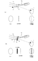
- FIG. 5A shows a HUD 10x as a comparative example when the mask image display 13 is not provided.
- the display image light L1 is emitted from the light source 11 to the combiner 12.
- the user 7 visually recognizes the display image.
- the contrast of the display image is lowered and the visibility is lowered. That is, the display image is buried in the external light, and the display image is difficult to identify from the image viewed by the user.
- the reflectivity of the combiner 12 when the reflectivity of the combiner 12 is low, the light leakage of the display image light L1 increases as shown by a bold broken line.
- the light leakage of the display image light L1 increases, a driver or a pedestrian of the vehicle traveling in the direction opposite to the vehicle traveling direction may recognize the display image.
- FIG. 10 An example of the HUD 10 according to this embodiment is shown in FIG.
- a mask image display body 13 is provided on the back surface of the combiner 12. Since a mask image having a mask area with low transmittance is displayed on the mask image display body 13, a reduction in contrast of the display image can be prevented even if the external light Lo is strong in the mask image area. Can be ensured. It is also possible to prevent the display image from being seen from the outside of the vehicle.
- the left-eye mask area 41L and the right-eye mask area 41R are created.
- the mask area 41L for the left eye is observed with the right eye as well as with the left eye.
- the mask region 41R for the right eye is observed with the left eye simultaneously with the right eye.
- the mask area 41R for the right eye observed with the left eye and the mask area 41L for the left eye observed with the right eye are observed at substantially the same position. Therefore, when a virtual image is observed with both eyes, three mask images are recognized at the same time, and as a whole, the size of the mask image may be larger than expected.
- the position where the mask image is drawn should be close enough to the observer. That is, it is only necessary that the mask area 41L for the left eye does not enter the viewing angle of the right eye and the mask area 41R for the right eye does not enter the viewing angle of the left eye so close to the observer.
- the combiner should be close to the observer.
- a mode in which a combiner is attached to a helmet worn by a user is also conceivable, but in this case, a mode similar to a head-mounted display as described in Modification Example 3 below will be used.
- a photochromic material is used as the mask image display body 13, and the mask image light is emitted from the mask image light source 22 to display the mask image on the mask image display body 13.
- a liquid crystal display can be used as the mask image display 13.
- a liquid crystal controller may be provided instead of the mask image light source 22, and the liquid crystal controller may drive the liquid crystal element of the liquid crystal display according to the mask image generated by the mask image generator 24 to display the mask image. Thereby, the transmittance of the mask area included in the mask image can be lowered.
- the present invention is applied to the HUD, but the present invention may be applied to a head mounted display (HMD) instead. Since the head mounted display also includes a light source section and an optical member corresponding to a combiner, a mask image display body may be provided on the optical member to display a mask image.
- HMD head mounted display
- the present invention can be used for a display system using a transmissive display.
- it can be used for a head-up display installed on a moving body such as a vehicle, a head-mounted display mounted on a user's head, and the like.
Landscapes
- Engineering & Computer Science (AREA)
- Chemical & Material Sciences (AREA)
- Combustion & Propulsion (AREA)
- Transportation (AREA)
- Mechanical Engineering (AREA)
- Physics & Mathematics (AREA)
- General Physics & Mathematics (AREA)
- Optics & Photonics (AREA)
- Instrument Panels (AREA)
Abstract
L'objet de la présente invention est de fournir un dispositif d'affichage permettant d'améliorer la visibilité d'une image affichée et de réduire l'infiltration de lumière au-delà de la vitre avant ainsi que la charge supportée par les yeux de l'utilisateur. Le présent dispositif d'affichage (10) comprend : une première source de lumière permettant l'émission d'une lumière d'image affichée formant une image affichée visible par l'utilisateur ; un élément optique (12) présentant une transmittance et une réflectivité prédéterminées, qui transmet une partie de la lumière (L1) émise depuis la première source de lumière et réfléchit le reste de la lumière et qui rend l'image affichée visible par l'utilisateur sous la forme d'une image virtuelle ; et un moyen de commande de transmittance (13) permettant de réduire la transmittance de l'élément optique dans la zone illuminée par la lumière de l'image affichée émise depuis la première source de lumière ainsi qu'une zone périphérique entourant la zone susmentionnée.
Priority Applications (1)
| Application Number | Priority Date | Filing Date | Title |
|---|---|---|---|
| PCT/JP2012/054937 WO2013128573A1 (fr) | 2012-02-28 | 2012-02-28 | Dispositif d'affichage et procédé d'affichage |
Applications Claiming Priority (1)
| Application Number | Priority Date | Filing Date | Title |
|---|---|---|---|
| PCT/JP2012/054937 WO2013128573A1 (fr) | 2012-02-28 | 2012-02-28 | Dispositif d'affichage et procédé d'affichage |
Publications (1)
| Publication Number | Publication Date |
|---|---|
| WO2013128573A1 true WO2013128573A1 (fr) | 2013-09-06 |
Family
ID=49081825
Family Applications (1)
| Application Number | Title | Priority Date | Filing Date |
|---|---|---|---|
| PCT/JP2012/054937 Ceased WO2013128573A1 (fr) | 2012-02-28 | 2012-02-28 | Dispositif d'affichage et procédé d'affichage |
Country Status (1)
| Country | Link |
|---|---|
| WO (1) | WO2013128573A1 (fr) |
Cited By (6)
| Publication number | Priority date | Publication date | Assignee | Title |
|---|---|---|---|---|
| JP2015069111A (ja) * | 2013-09-30 | 2015-04-13 | 株式会社Jvcケンウッド | 画像表示装置、スクリーンおよび画像表示方法 |
| JP2015160572A (ja) * | 2014-02-28 | 2015-09-07 | 株式会社デンソー | ヘッドアップディスプレイ装置 |
| WO2015136874A1 (fr) * | 2014-03-13 | 2015-09-17 | パナソニックIpマネジメント株式会社 | Dispositif de commande d'affichage, dispositif d'affichage, programme de commande d'affichage, procédé de commande d'affichage et support d'enregistrement |
| EP3031654A1 (fr) * | 2014-12-10 | 2016-06-15 | Valeo Schalter und Sensoren GmbH | Appareil d'affichage pour un véhicule automobile comprenant un dispositif écran, système d'assistance au conducteur, véhicule et procédé |
| WO2019073688A1 (fr) * | 2017-10-11 | 2019-04-18 | ソニー株式会社 | Dispositif d'affichage d'image |
| WO2020100674A1 (fr) * | 2018-11-14 | 2020-05-22 | 株式会社デンソー | Dispositif d'affichage |
Citations (4)
| Publication number | Priority date | Publication date | Assignee | Title |
|---|---|---|---|---|
| JPH08160340A (ja) * | 1994-12-05 | 1996-06-21 | Canon Inc | 画像観察装置 |
| JP2010521347A (ja) * | 2007-03-05 | 2010-06-24 | ザ・ボーイング・カンパニー | ヘッドアップディスプレイ用の電気的に減光可能なコンバイナ |
| JP2011002660A (ja) * | 2009-06-18 | 2011-01-06 | Honda Motor Co Ltd | 車両用画像表示装置 |
| JP4847627B1 (ja) * | 2010-09-21 | 2011-12-28 | パイオニア株式会社 | 表示装置 |
-
2012
- 2012-02-28 WO PCT/JP2012/054937 patent/WO2013128573A1/fr not_active Ceased
Patent Citations (4)
| Publication number | Priority date | Publication date | Assignee | Title |
|---|---|---|---|---|
| JPH08160340A (ja) * | 1994-12-05 | 1996-06-21 | Canon Inc | 画像観察装置 |
| JP2010521347A (ja) * | 2007-03-05 | 2010-06-24 | ザ・ボーイング・カンパニー | ヘッドアップディスプレイ用の電気的に減光可能なコンバイナ |
| JP2011002660A (ja) * | 2009-06-18 | 2011-01-06 | Honda Motor Co Ltd | 車両用画像表示装置 |
| JP4847627B1 (ja) * | 2010-09-21 | 2011-12-28 | パイオニア株式会社 | 表示装置 |
Cited By (11)
| Publication number | Priority date | Publication date | Assignee | Title |
|---|---|---|---|---|
| JP2015069111A (ja) * | 2013-09-30 | 2015-04-13 | 株式会社Jvcケンウッド | 画像表示装置、スクリーンおよび画像表示方法 |
| JP2015160572A (ja) * | 2014-02-28 | 2015-09-07 | 株式会社デンソー | ヘッドアップディスプレイ装置 |
| WO2015136874A1 (fr) * | 2014-03-13 | 2015-09-17 | パナソニックIpマネジメント株式会社 | Dispositif de commande d'affichage, dispositif d'affichage, programme de commande d'affichage, procédé de commande d'affichage et support d'enregistrement |
| EP3118047A4 (fr) * | 2014-03-13 | 2017-04-05 | Panasonic Intellectual Property Management Co., Ltd. | Dispositif de commande d'affichage, dispositif d'affichage, programme de commande d'affichage, procédé de commande d'affichage et support d'enregistrement |
| JPWO2015136874A1 (ja) * | 2014-03-13 | 2017-04-06 | パナソニックIpマネジメント株式会社 | 表示制御装置、表示装置、表示制御プログラム、表示制御方法、及び記録媒体 |
| US10013951B2 (en) | 2014-03-13 | 2018-07-03 | Panasonic Intellectual Property Management Co., Ltd. | Display control device, display device, display control program, display control method, and recording medium |
| EP3031654A1 (fr) * | 2014-12-10 | 2016-06-15 | Valeo Schalter und Sensoren GmbH | Appareil d'affichage pour un véhicule automobile comprenant un dispositif écran, système d'assistance au conducteur, véhicule et procédé |
| WO2019073688A1 (fr) * | 2017-10-11 | 2019-04-18 | ソニー株式会社 | Dispositif d'affichage d'image |
| US11187898B2 (en) | 2017-10-11 | 2021-11-30 | Sony Corporation | Image display apparatus |
| WO2020100674A1 (fr) * | 2018-11-14 | 2020-05-22 | 株式会社デンソー | Dispositif d'affichage |
| JP2020079917A (ja) * | 2018-11-14 | 2020-05-28 | 株式会社デンソー | 表示装置 |
Similar Documents
| Publication | Publication Date | Title |
|---|---|---|
| JP7370340B2 (ja) | ヘッドアップディスプレイ上での拡張現実エクスペリエンスの強化 | |
| JP6699675B2 (ja) | 情報提供装置 | |
| JP6437532B2 (ja) | グレア防止スクリーンを備えるデータ表示眼鏡 | |
| EP3919961B1 (fr) | Dispositif d'affichage tête haute | |
| CN104827967B (zh) | 平视显示设备 | |
| KR20190017983A (ko) | 사용자의 시야에 가상 이미지를 중첩시키기 위한 디스플레이 장치 | |
| WO2013128573A1 (fr) | Dispositif d'affichage et procédé d'affichage | |
| JP2010262161A (ja) | 表示装置、表示方法及び車両 | |
| JP2009126249A (ja) | 車両用情報表示装置 | |
| JP6669053B2 (ja) | ヘッドアップディスプレイシステム | |
| JP2015194709A (ja) | 画像表示装置 | |
| CN210666205U (zh) | 一种抬头显示设备、成像系统和车辆 | |
| KR101484204B1 (ko) | 헤드업 디스플레이장치의 커버 및 이를 포함한 하우징 | |
| JP2009092810A (ja) | ヘッドマウントディスプレイ装置 | |
| US20180345867A1 (en) | Display system, electronic mirror system, and moving body | |
| JP6136884B2 (ja) | 車両用表示装置 | |
| CN211375182U (zh) | 一种抬头显示设备、成像系统和车辆 | |
| KR20160062018A (ko) | 눈부심 방지 스크린을 포함하는 데이터 표시 안경 | |
| JP2016121891A (ja) | 表示装置 | |
| JP6105531B2 (ja) | 車両用投影表示装置 | |
| CN113614613B (zh) | 立体虚像显示模块、立体虚像显示系统以及移动体 | |
| JP2010156929A (ja) | 表示装置 | |
| KR20170134670A (ko) | 차량용 표시 장치 | |
| JP2015045690A (ja) | ヘッドアップディスプレイ及び投影装置 | |
| JP2017105245A (ja) | ヘッドアップディスプレイ装置 |
Legal Events
| Date | Code | Title | Description |
|---|---|---|---|
| 121 | Ep: the epo has been informed by wipo that ep was designated in this application |
Ref document number: 12870205 Country of ref document: EP Kind code of ref document: A1 |
|
| NENP | Non-entry into the national phase |
Ref country code: DE |
|
| 122 | Ep: pct application non-entry in european phase |
Ref document number: 12870205 Country of ref document: EP Kind code of ref document: A1 |
|
| NENP | Non-entry into the national phase |
Ref country code: JP |