WO2013128708A1 - Machine à fouetter réfrigérante - Google Patents
Machine à fouetter réfrigérante Download PDFInfo
- Publication number
- WO2013128708A1 WO2013128708A1 PCT/JP2012/077691 JP2012077691W WO2013128708A1 WO 2013128708 A1 WO2013128708 A1 WO 2013128708A1 JP 2012077691 W JP2012077691 W JP 2012077691W WO 2013128708 A1 WO2013128708 A1 WO 2013128708A1
- Authority
- WO
- WIPO (PCT)
- Prior art keywords
- container
- cooling
- shaft
- rotating shaft
- cold
- Prior art date
- Legal status (The legal status is an assumption and is not a legal conclusion. Google has not performed a legal analysis and makes no representation as to the accuracy of the status listed.)
- Ceased
Links
Images


Classifications
-
- A—HUMAN NECESSITIES
- A23—FOODS OR FOODSTUFFS; TREATMENT THEREOF, NOT COVERED BY OTHER CLASSES
- A23G—COCOA; COCOA PRODUCTS, e.g. CHOCOLATE; SUBSTITUTES FOR COCOA OR COCOA PRODUCTS; CONFECTIONERY; CHEWING GUM; ICE-CREAM; PREPARATION THEREOF
- A23G9/00—Frozen sweets, e.g. ice confectionery, ice-cream; Mixtures therefor
- A23G9/04—Production of frozen sweets, e.g. ice-cream
- A23G9/08—Batch production
- A23G9/12—Batch production using means for stirring the contents in a non-moving container
-
- A—HUMAN NECESSITIES
- A23—FOODS OR FOODSTUFFS; TREATMENT THEREOF, NOT COVERED BY OTHER CLASSES
- A23G—COCOA; COCOA PRODUCTS, e.g. CHOCOLATE; SUBSTITUTES FOR COCOA OR COCOA PRODUCTS; CONFECTIONERY; CHEWING GUM; ICE-CREAM; PREPARATION THEREOF
- A23G9/00—Frozen sweets, e.g. ice confectionery, ice-cream; Mixtures therefor
- A23G9/04—Production of frozen sweets, e.g. ice-cream
- A23G9/22—Details, component parts or accessories of apparatus insofar as not peculiar to a single one of the preceding groups
- A23G9/224—Agitators or scrapers
-
- A—HUMAN NECESSITIES
- A23—FOODS OR FOODSTUFFS; TREATMENT THEREOF, NOT COVERED BY OTHER CLASSES
- A23G—COCOA; COCOA PRODUCTS, e.g. CHOCOLATE; SUBSTITUTES FOR COCOA OR COCOA PRODUCTS; CONFECTIONERY; CHEWING GUM; ICE-CREAM; PREPARATION THEREOF
- A23G9/00—Frozen sweets, e.g. ice confectionery, ice-cream; Mixtures therefor
- A23G9/04—Production of frozen sweets, e.g. ice-cream
- A23G9/22—Details, component parts or accessories of apparatus insofar as not peculiar to a single one of the preceding groups
- A23G9/225—Ice-cream freezing and storing cabinets
-
- A—HUMAN NECESSITIES
- A47—FURNITURE; DOMESTIC ARTICLES OR APPLIANCES; COFFEE MILLS; SPICE MILLS; SUCTION CLEANERS IN GENERAL
- A47J—KITCHEN EQUIPMENT; COFFEE MILLS; SPICE MILLS; APPARATUS FOR MAKING BEVERAGES
- A47J43/00—Implements for preparing or holding food, not provided for in other groups of this subclass
- A47J43/12—Whipping by introducing a stream of gas
- A47J43/121—Devices using a static mixing element; Static mixing elements therefor
- A47J43/122—Devices using a static mixing element; Static mixing elements therefor the mixing element being of considerable length, e.g. labyrinth-type mixing elements
- A47J43/123—Self-contained units for making whipped cream
Definitions
- the present invention relates to a cooling whisk for producing a frozen foam.
- Patent Document 1 a manufacturing apparatus that can easily manufacture ice cream at home is known (for example, Patent Document 1).
- an ice cream material is manufactured by storing an ice cream material in a storage chamber surrounded by a cooling chamber and stirring it with a stirring blade.
- Patent Document 1 since the stirring blade (blade) is smaller than the storage chamber, the material that begins to freeze from the surface adjacent to the cooling chamber cannot be stirred uniformly and efficiently, and the stirring blade is fixed to the lid. For this reason, there is a drawback that not only the stirring flow path becomes constant but also a creamy frozen ice cream cannot be produced by mixing outside air.
- a whisk having a structure in which a blade is hollow and an outside air inlet is provided at the top of the blade and an outside air outlet is provided at the bottom of the blade is known (for example, Patent Document 2).
- any kind of beverage can be used as long as it is a sparkling beverage containing a cereal decomposition product, but it is particularly preferable.
- beverages containing malt and barley decomposition products are not particularly limited as long as they are cereals, but are preferably barley, wheat, soybeans, and peas, and more preferably barley.
- cereals are not particularly limited as long as they are cereals, but are preferably barley, wheat, soybeans, and peas, and more preferably barley.
- it does not specifically limit as a concrete aspect of the decomposition product of cereals, it is a decomposition product of malt, barley, wheat, soybean, pea, corn, for example, soybean protein, soybean peptide, pea protein, corn protein decomposition Things.
- the beer-based beverage usually refers to a beverage having a beer-specific taste and aroma obtained when beer is produced, that is, when beer is produced based on fermentation by yeast or the like, for example, Non-fermented malt beverages such as fermented malt beverages such as beer, sparkling liquor and liqueur, other brewed liquors, and completely alcohol-free malt beverages (non-alcoholic malt beverages).
- Non-fermented malt beverages such as fermented malt beverages such as beer, sparkling liquor and liqueur, other brewed liquors, and completely alcohol-free malt beverages (non-alcoholic malt beverages).
- non-alcoholic malt beverages non-alcoholic malt beverages
- it is not limited to a malt drink, The form of the non-wheat drink which does not use wheat and malt may be sufficient.
- the present invention has been made in order to solve the above-described problems.
- sufficient cooling including cereal decomposition product-containing sparkling beverages such as beer-based beverages
- it is easy to involve outside air by sufficient agitation at home. It aims to provide a cooling whisk that can be realized.
- the cooling whisk according to claim 1 comprises a cold-insulated container having a bottomed cylindrical inner wall for cooling a food and drink material foamed by stirring, and an apparatus main body, wherein the apparatus main body is substantially at the center of the cold-insulated container.
- a rotating shaft capable of rotating and moving up and down in the unit, and rotating and moving up and down together with the rotating shaft to stir the material in the cold container and adhere to the inner wall of the cold container
- a driving device that moves the rotating shaft up and down while rotating the rotating shaft, and the rotating shaft and the blade are inserted into the cold storage container.
- the cooling whisk according to claim 2 is the cooling whisk according to claim 1, characterized in that the cold container is a double container of an inner container and an outer container.
- a cooling whisk according to claim 3 is the cooling whisk according to claim 1 or 2, wherein a plurality of the blades are provided in a circumferential direction of the rotating shaft.
- the cooling whisk according to claim 4 is the cooling whisk according to any one of claims 1 to 3, wherein a universal joint is interposed between the driving device and the blade on the rotating shaft. It is characterized by being.
- a cooling whisk according to claim 5 is the cooling whisk according to any one of claims 1 to 4, wherein an inner portion of the rotating shaft is attached to the rotating shaft so as to be idle and an outer portion. Is provided with a protective member that abuts against the inner wall of the cold container and forms a predetermined clearance between the blade and the inner wall of the cold container.
- the cooling whisk according to claim 6 is the cooling whisk according to any one of claims 1 to 5, wherein the driving device reciprocally rotates the rotating shaft within a predetermined angle range in the cold storage container. It is configured to be moved.
- the cooling whisk according to claim 7 is the cooling whisk according to any one of claims 1 to 6, wherein the blades are formed in a bar shape or a flat plate shape arranged in a comb shape in the axial direction of the rotating shaft. It is characterized by comprising a blade piece.
- the cooling whisk according to claim 8 is the cooling whisk according to any one of claims 1 to 7, wherein the raw material is a cereal decomposition product-containing sparkling beverage.
- a cooling whisk according to claim 9 is the cooling whisk according to any one of claims 1 to 8, wherein the material is a beer-based beverage.
- the cooling whisk of claim 1 even if the blade has a simple structure, the air is sufficiently entrained in the material by moving the blade up and down while rotating in the cold container via the rotating shaft.
- the stirring flow is irregular, the entire material can be cooled and stirred uniformly and efficiently, so that a refreshing texture like snow and a foam with a creamy frozen state can be made.
- the ice adhering to the inner wall of the cold storage container can be scraped off by the blades, it is possible to prevent the formation of large ice blocks on the inner wall side of the cold storage container where the contained material is likely to freeze, and small ice blocks Can be efficiently stirred and mixed in the raw material, so that it is possible to produce a frozen foam with a new texture (crispness).
- the cold insulation container is a double container of the inner container and the outer container, the raw material can be obtained by putting a refrigerant or other coolant in the outer container. It can be cooled sufficiently.
- the material in the cold insulation container can be efficiently stirred, and the desired frozen state can be quickly obtained.
- a foam can be made.
- the shaft for transmitting power from the driving device and the center of the cold container are displaced. Even if it is, the blades operate reliably in the cold container.
- the protective member since the protective member maintains an appropriate clearance between the tip of the blade and the inner wall of the container, the blade slides on the inner wall of the cold container during the rotation operation and the vertical movement operation. Since it does not touch, damage to the inner wall of the blade and the cold container can be prevented.
- cooling whisk of the sixth aspect since the rotating shaft reciprocates within a predetermined angular range in the container, turbulent flow is formed, and air can be effectively taken into the material, and the desired speed can be quickly obtained. A frozen foam can be made.
- the blades are constituted by a plurality of rod-like or flat blade pieces arranged in a comb-teeth shape in the axial direction of the rotation shaft, the blades rotate and move up and down.
- the material can be evenly stirred in the depth direction of the cold storage container, and the ice attached to the inner wall of the cold storage container can be evenly scraped in the depth direction of the cold storage container. Therefore, a desired frozen foam can be quickly produced.
- cooling whisk of the eighth aspect it is possible to easily make a frozen foam of the cereal decomposition product-containing sparkling beverage.
- cooling whisk of the ninth aspect it is possible to easily make a frozen foam of a beer-based beverage.
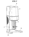
- FIG. 1 is a perspective view of a cooling bubbler.
- the cooling whisk 100 is a stationary type, and includes an apparatus main body 10, a cold insulation container 50, and two large and small spoons 70 and 71.
- the cooling whisk 100 is large enough to be carried with one hand.
- details of the cooling whisk 100 will be described.
- the apparatus body 10 includes a support column 11 and a mechanism unit 12 held at a predetermined height by the support column 11.
- Two legs 11 a and 11 a are provided at the lower end of the column 11.
- a battery housing part (not shown) is provided in the support column part 11, and a plurality of single batteries are housed in the battery housing part.
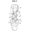
- the mechanism unit 12 is provided with a driving device A as shown in FIG.
- the drive device A includes a motor 13 and a power transmission mechanism 15 that transmits power of the motor 13 to a rotating shaft 14 described later.
- the power transmission mechanism 15 transmits the power of the motor 13 to move the rotary shaft 14 having an axis extending in the vertical direction up and down and to reciprocate the rotary shaft 14 within a predetermined angle range.
- the power transmission mechanism 15 rotates the drum 16 through the gears 15a, 15b, 15c, 15d, 15e, 15f, 15g, 15h, 15i, 15j, 15k, and 15l.
- the drum 16 rotates about an axis parallel to the rotation shaft 14.
- This drum 16 has a cam groove 16a on its peripheral surface, and constitutes a cam base.
- the rotating shaft 14 has a cam follower 140 that engages with the cam groove 16a, and constitutes a cam follower.
- the cam follower 140 operates following the cam groove 16a to move the rotary shaft 14 up and down once.
- the completed bubbles float on the surface of the material and become a lump, but when the vertical movement of the blades 26 is also added, the bubbles are pushed into the material. Thus, the entire material can be effectively foamed.
- the stroke of the vertical movement of the rotating shaft 14 is about 1.5 cm, but is not limited thereto.
- the long hole 18a is engaged with a protrusion 19a provided at an eccentric position of the rotating body 19 that rotates integrally with the gear 15h.
- the rotary shaft 14 is provided with a gear 20 that meshes with the sector gear 18.
- the operating angle of the rotating shaft 14 be 120 ° or more. In this way, the ice around the inner wall of the inner container 52 can be scraped off by three blades 26 described later.
- Rotating shaft 14 constitutes an axis of a blade 26 described later.
- the rotary shaft 14 is configured by connecting a first shaft 14a, a second shaft 14b, a third shaft 14c, and a fourth shaft 14d in this order from above (see FIGS. 3 and 4).
- the entire rotating shaft 14 extends in the vertical direction, and a part of the rotating shaft 14 protrudes from below the mechanism portion 12 as shown in FIG. Of these, the cam follower 140 and the gear 20 are provided on the first shaft 14a.
- the second shaft 14b forms a universal joint.
- the second shaft 14b is configured by connecting six connecting pieces 21a, 21b, 21c, 21d, 21e, and 21f in this order from the upper side.
- each of the four connection pieces 21b, 21c, 21d, and 21e excluding the uppermost connection piece 21a and the lowermost connection piece 21f is connected via a shaft 24 having an axis extending in one direction.
- the upper end is connected to the connecting piece directly above, and the lower end is connected to the connecting piece directly below via a shaft 24 having an axis extending in a direction orthogonal to the one direction in plan view.
- connection piece 21a having no connection piece immediately above is detachably connected to the first shaft 14a immediately above by concave-convex fitting. The reason why it is detachable is to facilitate cleaning by disassembly.
- the lowermost connection piece 21f that does not have a connection piece directly below is detachably connected to the third shaft 14c directly below by concave and convex fitting. The reason why it is detachable is to facilitate cleaning by attaching or disassembling a protective member 27 described later.
- shaft 14b comprised in this way is flexible so that the shift
- the dimension from the center of the third shaft 14c and the fourth shaft 14d to the tip of the blade piece 26a is about 1 mm smaller than the dimension from the center of the inner container 52 described later to the inner wall.
- wing 26 is the scraping function which scrapes off the ice adhering to the inner wall of the cold storage container 50, and the stirring function which stirs the cereal decomposition product containing effervescent drink put into the cold storage container 50, and its frozen foam. And have.
- Protection member 27 A protective member 27 is provided at the lower end of the second shaft 14b and the upper end of the fourth shaft 14d.
- the protective member 27 includes a ring 27a that fits idle on the lower end of the second shaft 14b or the upper end of the fourth shaft 14d, and three tension rods 27b that extend in the radial direction of the ring 27a. ing.
- the three tension rods 27b are provided one by one at equal intervals in the circumferential direction of the ring 27a.
- the dimension from the center of the protective member 27 to the tip of the tension rod 27b is slightly smaller than the dimension from the center to the inner wall of the inner container 52 described later.
- the protective member 27 is configured such that when the blades 26 are reciprocally rotated within a predetermined angle range, the tip portions of the three tension rods 27b come into contact with inner walls of the inner container 52 to be described later. By forming an appropriate clearance (a clearance of about 1 mm or less) with the wall surface, the sliding contact with each other is prevented and the inner container 52 is prevented from being damaged.
- the protective member 27 functions to effectively scrape off the ice on the inner wall of the inner container 52 by forming an appropriate clearance between the blade 26 and the wall surface of the inner container 52. Incidentally, in this case, if the clearance is about 1.5 mm, the ice on the inner wall of the inner container 52 is scraped off as a lump, and the texture of the frozen foam is impaired.
- a plurality of the protection members 27 are provided at positions below the portion functioning as a universal joint and at positions separated in the axial direction of the rotary shaft 14. If a plurality of protective members 27 are provided in this way, all the blade pieces 26 a do not contact the inner wall of the inner container 52. However, it is not preferable to provide the blade 26 below the lowermost blade piece 26a. This is because the protective member 27 is provided on the rotary shaft 14 so as to be able to idle, so that when it is provided below the lowermost blade piece 26a of the blade 26, the ice at the bottom of the inner container 52 described later can be scraped off. Because it becomes impossible.
- FIG. 8 is an assembly view of the cold container 50
- FIG. 9 is an exploded view of the cold container 50.
- the cold container 50 includes a transparent outer container 51 made of plastic, an inner container 52 made of aluminum, large and small silicon rings 53 and 54, and ring-shaped upper lid 55 and lower lid 56.
- the outer container 51 has an outward flange 51a at the upper end, and a cylindrical frame 51b that stands upward from the outer periphery of the flange 51a and surrounds the flange 51a.
- a silicon ring 53 is placed on the outward flange 51a.
- the lower lid 56 is fitted inside the frame body 51b of the frame body 51b at a predetermined position.
- the protruding piece 56a of the lower lid 56 sinks below the locking portion 51c inside the frame 51b, and the protruding piece 56a is locked. It is locked by the part 51c.
- the lower lid 56 is attached to the outer container 51.
- the inner container 52 is inserted into the opening of the lower lid 56 attached to the outer container 51 from above.
- the outward flange 52 a at the upper end of the inner container 52 gets on the inward flange 56 b of the lower lid 56.
- the inner container 52 is held in a state slightly separated from the bottom surface of the outer container 51.
- the insertion is guided and held at a predetermined position of the outer container 51 by the guide rib 51 d formed inside the outer container 51.
- the silicon ring 54 is placed on the outward flange 52 a of the inner container 52.
- the upper lid 55 is fitted to the frame 56c outside the inward flange 56b of the lower lid 56 at a predetermined position. Then, by rotating the upper lid 55 in a predetermined direction while pressing the upper lid 55 against the inner container 52 on which the silicon ring 54 is placed on the outward flange 52a, the projecting piece 55a of the upper lid 55 is located below the engaging portion 56c of the lower lid 56. The projecting piece 55a is locked by the locking portion 56c. Thereby, the assembly of the cold container 50 is completed.
- the cold insulation container 50 assembled in this manner is fitted into a cover member 57 (see a perspective view seen from the lower side of FIG. 10) under the mechanism portion 12 of the apparatus main body 10 at a predetermined position. Then, by rotating the cold insulation container 50 in a predetermined direction while pressing the cold insulation container 50 against the cover member 57 side, the protruding piece 56d of the lower lid 56 is engaged with the engagement piece 57a of the cover member 57, whereby the cold insulation container 50 is It is attached to the apparatus main body 10.
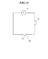
- Safety device 80 The frame 51b of the outer container 51 is provided with a tongue-like protrusion 51e.
- the protrusion 51e is a normally open safety switch 81 (provided on the apparatus main body 10) by contact of the protrusion 51e when the cold container 50 is rotated in a predetermined direction when the cold container 50 is attached to the apparatus main body 10. 11) is turned ON.
- the motor 13 does not operate unless the power switch 82 is turned on while the safety switch 81 is turned on.
- such a safety device 80 is provided, and the device is devised so that the motor 13 does not operate when the blades 26 are exposed.
- a usage method of the cooling whisk 100 will be described.
- the case where a frozen foam is made using a cereal decomposition product-containing sparkling beverage as a raw material will be described as an example.
- the upper cover 55 and the lower cover 56 of the cold container 50 are removed, and the cold container 50 is divided into parts.
- the amount of salt is measured with the lightweight part 70a or 71a of the spoon 70 or 71 with a spatula, and a predetermined amount of salt and water are put into the outer container 51 and mixed well.
- the cold container 50 is assembled. Then, this cold container 50 is put in a freezer and left for 24 to 48 hours.
- the cold storage container 50 is taken out, and the cereal decomposition product-containing sparkling beverage is poured into the inner container 52 on the inside up to about 3 of the capacity of the inner container 52.
- the apparatus main body 10 is lowered and placed so that the blades 26 of the apparatus main body 10 lifted upward are put into the cold container 50 from above.
- the cold container 50 is lifted and rotated in a predetermined direction and attached to the apparatus main body 10.
- a power switch (not shown) is turned on to operate the driving device A and the blades 26.
- the moisture of the cereal decomposition product-containing sparkling beverage comes into contact with the wall surface of the inner container 52 and gradually freezes when it is poured into the inner container 52. And when the drive device A and the blade
- the cold container 50 is removed from the apparatus main body 10, and the foam is poured into the spatula 70b or 71b of the spoon 70 or 71 with a spatula and poured into a mug. Mix in a sparkling beverage containing cereal decomposition products and serve.
- the center of the inner container 52 and the center of the rotation shaft 14 must not be strictly aligned. Also, it can be easily inserted by bending the rotating shaft 14. In addition, even when the axis of the rotating shaft 14 and the axis of the inner container 52 are deviated, the blades 26 operate reliably in the inner container 52.
- the rotating shaft 14 is provided with a protective member 27.
- the protective member 27 is configured such that when the blades 26 are reciprocally rotated within a predetermined angular range, the tips of the three rods 27b abut against the inner wall of the inner container 52 described later. The contact prevents the blades 26 from sliding on the wall surface of the inner container 52 and prevents the inner wall of the inner container 52 from being damaged.
- the present invention is not limited to such embodiments, and it goes without saying that various modifications can be made without departing from the scope of the present invention.
- the blades 26 are arranged in a comb-like shape with rod-shaped blade pieces 26a, and three blades 26 are provided in the circumferential direction of the third shaft 14c and the fourth shaft 14d. It is also possible to use blades that are spirally wound around the third shaft 14c and the fourth shaft 14d. Furthermore, what provided the hole with the plate-shaped blade
- the container made from aluminum was used for the inner side container 52, you may use the container formed from stainless steel other materials.
- the said embodiment demonstrated the cereal decomposition product containing effervescent drink as a raw material of the foamed foam, a fresh cream and other raw materials can also be made into object. Any food and drink material that bubbles by stirring can be widely used.
- salt and water are used as the cooling material of the cold storage container 50, it is set as the structure where the cold storage agent and the Peltier element were attached to the cold storage container 50, or as the structure where the cooling pipe was attached to the cold storage container 50. Also good.
- the cereal decomposition product-containing sparkling beverage itself may be cooled in advance to near the freezing temperature.
- the cereal decomposition product-containing sparkling beverage is cooled by the cooled cold container 50.
- the apparatus main body 10 if the apparatus main body 10 is used, the cereal decomposition product-containing sparkling beverage side is sufficiently cooled.
- the frozen beverage containing the cereal decomposition product is put in a sherbet shape in a cold storage container 50 or a container without a cold storage function, and the frozen foam is also obtained by rotating and moving up and down the blades 26 in this container. It is possible to make.
- the present invention is useful in the field of producing a cooling whisk, and the field of providing a cereal decomposition product-containing sparkling beverage.
Landscapes
- Engineering & Computer Science (AREA)
- Food Science & Technology (AREA)
- Life Sciences & Earth Sciences (AREA)
- Chemical & Material Sciences (AREA)
- Polymers & Plastics (AREA)
- Manufacturing & Machinery (AREA)
- Mechanical Engineering (AREA)
- Confectionery (AREA)
- Devices For Dispensing Beverages (AREA)
Applications Claiming Priority (2)
| Application Number | Priority Date | Filing Date | Title |
|---|---|---|---|
| JP2012-042465 | 2012-02-28 | ||
| JP2012042465A JP5161378B1 (ja) | 2012-02-28 | 2012-02-28 | 冷却泡立て器 |
Publications (1)
| Publication Number | Publication Date |
|---|---|
| WO2013128708A1 true WO2013128708A1 (fr) | 2013-09-06 |
Family
ID=48013592
Family Applications (1)
| Application Number | Title | Priority Date | Filing Date |
|---|---|---|---|
| PCT/JP2012/077691 Ceased WO2013128708A1 (fr) | 2012-02-28 | 2012-10-26 | Machine à fouetter réfrigérante |
Country Status (2)
| Country | Link |
|---|---|
| JP (1) | JP5161378B1 (fr) |
| WO (1) | WO2013128708A1 (fr) |
Cited By (5)
| Publication number | Priority date | Publication date | Assignee | Title |
|---|---|---|---|---|
| IT201700005194A1 (it) * | 2017-01-18 | 2018-07-18 | Valmar Global Vse Za Sladoled D O O | Organo mescolatore rotante per macchine cuoci-crema e macchina cuoci-crema provvista di tale organo mescolatore |
| USD966799S1 (en) | 2020-09-04 | 2022-10-18 | Rich Products Corporation | Whipped product dispenser |
| US12102257B2 (en) | 2020-03-04 | 2024-10-01 | Rich Products Corporation | Food product dispenser with removable module |
| USD1074924S1 (en) | 2021-12-17 | 2025-05-13 | Rich Products Corporation | Filling tip attachment |
| US12402755B2 (en) | 2020-05-15 | 2025-09-02 | Rich Products Corporation | Injection-moldable aerator mixing rod and method of manufacturing thereof |
Citations (10)
| Publication number | Priority date | Publication date | Assignee | Title |
|---|---|---|---|---|
| JPS6471446A (en) * | 1987-09-10 | 1989-03-16 | Jitsuo Inagaki | Preparation of ice cream or the like and apparatus used therefor |
| JPH039192U (fr) * | 1989-06-09 | 1991-01-29 | ||
| JPH1156247A (ja) * | 1997-08-20 | 1999-03-02 | Izumi Food Mach:Kk | 冷菓製造機内の撹拌混合装置 |
| JP2002176920A (ja) * | 2000-12-13 | 2002-06-25 | Saitekku Corporation:Kk | ソフトクリーム製造機 |
| JP2003204760A (ja) * | 2002-01-16 | 2003-07-22 | Yoshinobu Toyomura | 氷菓製造器 |
| JP2003235458A (ja) * | 2002-02-20 | 2003-08-26 | Tiger Vacuum Bottle Co Ltd | 家庭用ソフトクリームの製造方法 |
| JP2004016108A (ja) * | 2002-06-17 | 2004-01-22 | Sumi Corporation:Kk | 冷菓及び冷菓製造装置 |
| JP2004180651A (ja) * | 2002-12-13 | 2004-07-02 | Tiger Vacuum Bottle Co Ltd | ソフトアイス飲料製造装置 |
| JP2004298163A (ja) * | 2003-03-28 | 2004-10-28 | Ttm:Kk | アイスクリーム製造器 |
| JP2004313182A (ja) * | 2003-04-01 | 2004-11-11 | Matsushita Electric Ind Co Ltd | アイスクリーム製造機及びその制御方法 |
-
2012
- 2012-02-28 JP JP2012042465A patent/JP5161378B1/ja not_active Expired - Fee Related
- 2012-10-26 WO PCT/JP2012/077691 patent/WO2013128708A1/fr not_active Ceased
Patent Citations (10)
| Publication number | Priority date | Publication date | Assignee | Title |
|---|---|---|---|---|
| JPS6471446A (en) * | 1987-09-10 | 1989-03-16 | Jitsuo Inagaki | Preparation of ice cream or the like and apparatus used therefor |
| JPH039192U (fr) * | 1989-06-09 | 1991-01-29 | ||
| JPH1156247A (ja) * | 1997-08-20 | 1999-03-02 | Izumi Food Mach:Kk | 冷菓製造機内の撹拌混合装置 |
| JP2002176920A (ja) * | 2000-12-13 | 2002-06-25 | Saitekku Corporation:Kk | ソフトクリーム製造機 |
| JP2003204760A (ja) * | 2002-01-16 | 2003-07-22 | Yoshinobu Toyomura | 氷菓製造器 |
| JP2003235458A (ja) * | 2002-02-20 | 2003-08-26 | Tiger Vacuum Bottle Co Ltd | 家庭用ソフトクリームの製造方法 |
| JP2004016108A (ja) * | 2002-06-17 | 2004-01-22 | Sumi Corporation:Kk | 冷菓及び冷菓製造装置 |
| JP2004180651A (ja) * | 2002-12-13 | 2004-07-02 | Tiger Vacuum Bottle Co Ltd | ソフトアイス飲料製造装置 |
| JP2004298163A (ja) * | 2003-03-28 | 2004-10-28 | Ttm:Kk | アイスクリーム製造器 |
| JP2004313182A (ja) * | 2003-04-01 | 2004-11-11 | Matsushita Electric Ind Co Ltd | アイスクリーム製造機及びその制御方法 |
Cited By (9)
| Publication number | Priority date | Publication date | Assignee | Title |
|---|---|---|---|---|
| IT201700005194A1 (it) * | 2017-01-18 | 2018-07-18 | Valmar Global Vse Za Sladoled D O O | Organo mescolatore rotante per macchine cuoci-crema e macchina cuoci-crema provvista di tale organo mescolatore |
| EP3351113A1 (fr) * | 2017-01-18 | 2018-07-25 | Valmar Global VSE ZA Sladoled D.O.O. | Organe melangeur rotatif pour machines pour la cuisson de creme patissieres et machine pour la production de creme patissiere comprenant ledit organe melangeur |
| US12102257B2 (en) | 2020-03-04 | 2024-10-01 | Rich Products Corporation | Food product dispenser with removable module |
| US12402755B2 (en) | 2020-05-15 | 2025-09-02 | Rich Products Corporation | Injection-moldable aerator mixing rod and method of manufacturing thereof |
| USD966799S1 (en) | 2020-09-04 | 2022-10-18 | Rich Products Corporation | Whipped product dispenser |
| USD1057502S1 (en) | 2020-09-04 | 2025-01-14 | Rich Products Corporation | Whipped product dispenser |
| USD1084759S1 (en) | 2020-09-04 | 2025-07-22 | Rich Products Corporation | Whipped product dispenser |
| USD1106735S1 (en) | 2020-09-04 | 2025-12-23 | Rich Products Corporation | Whipped product dispenser |
| USD1074924S1 (en) | 2021-12-17 | 2025-05-13 | Rich Products Corporation | Filling tip attachment |
Also Published As
| Publication number | Publication date |
|---|---|
| JP2013176326A (ja) | 2013-09-09 |
| JP5161378B1 (ja) | 2013-03-13 |
Similar Documents
| Publication | Publication Date | Title |
|---|---|---|
| CN203262198U (zh) | 一种冰淇淋机 | |
| US10674742B2 (en) | System and method for making ice cream | |
| JP6823149B2 (ja) | 空気混入した、又は泡立った質感を備える低温食品を、制御された方法で調製するためのマシン及びシステム | |
| JP5161378B1 (ja) | 冷却泡立て器 | |
| US4392361A (en) | Self-contained ice cream apparatus | |
| CN203207110U (zh) | 一种冰淇淋机 | |
| CN105682469B (zh) | 用于制备具有充气质构的冷却糖食产品的机器、系统和方法 | |
| CN103211076B (zh) | 一种冰淇淋机 | |
| US4551026A (en) | Household appliance for making ice cream | |
| CN103262936A (zh) | 一种冰淇淋机 | |
| EP3222150B1 (fr) | Machine et procédé de fabrication de produits liquides ou semi-liquides | |
| US20140130538A1 (en) | Wooden ice cream maker | |
| US20170021315A1 (en) | Paddle agitator | |
| EP3250046B1 (fr) | Appareil de préparation de crème glacée et de produits congelés similaires | |
| CN101918774A (zh) | 在单份杯中搅拌饮料的方法 | |
| KR20190130499A (ko) | 액체 또는 반액체 식품을 제조하기 위한 기계 | |
| US7412845B2 (en) | Ice cream maker including nestable canister assembly | |
| US11684216B2 (en) | Reverse draft open top blending container | |
| WO2018134573A1 (fr) | Appareil de mélange | |
| CN102613379A (zh) | 一种自动冰淇淋机 | |
| US20170027187A1 (en) | Rigid agitator for blender system | |
| CN110279026A (zh) | 一种冰淇淋机搅拌轴及冰淇淋机 | |
| JP3757934B2 (ja) | ソフトアイス飲料製造装置 | |
| CN205697114U (zh) | 一种搅拌杯 | |
| US20190077569A1 (en) | Container design with built-in overrun meter |
Legal Events
| Date | Code | Title | Description |
|---|---|---|---|
| 121 | Ep: the epo has been informed by wipo that ep was designated in this application |
Ref document number: 12869705 Country of ref document: EP Kind code of ref document: A1 |
|
| NENP | Non-entry into the national phase |
Ref country code: DE |
|
| 122 | Ep: pct application non-entry in european phase |
Ref document number: 12869705 Country of ref document: EP Kind code of ref document: A1 |