WO2013129384A1 - Colonne d'adsorption - Google Patents
Colonne d'adsorption Download PDFInfo
- Publication number
- WO2013129384A1 WO2013129384A1 PCT/JP2013/054936 JP2013054936W WO2013129384A1 WO 2013129384 A1 WO2013129384 A1 WO 2013129384A1 JP 2013054936 W JP2013054936 W JP 2013054936W WO 2013129384 A1 WO2013129384 A1 WO 2013129384A1
- Authority
- WO
- WIPO (PCT)
- Prior art keywords
- hollow fiber
- fiber membrane
- adsorption column
- blood
- adsorption
- Prior art date
- Legal status (The legal status is an assumption and is not a legal conclusion. Google has not performed a legal analysis and makes no representation as to the accuracy of the status listed.)
- Ceased
Links
Images


Classifications
-
- B—PERFORMING OPERATIONS; TRANSPORTING
- B01—PHYSICAL OR CHEMICAL PROCESSES OR APPARATUS IN GENERAL
- B01J—CHEMICAL OR PHYSICAL PROCESSES, e.g. CATALYSIS OR COLLOID CHEMISTRY; THEIR RELEVANT APPARATUS
- B01J20/00—Solid sorbent compositions or filter aid compositions; Sorbents for chromatography; Processes for preparing, regenerating or reactivating thereof
- B01J20/28—Solid sorbent compositions or filter aid compositions; Sorbents for chromatography; Processes for preparing, regenerating or reactivating thereof characterised by their form or physical properties
- B01J20/28014—Solid sorbent compositions or filter aid compositions; Sorbents for chromatography; Processes for preparing, regenerating or reactivating thereof characterised by their form or physical properties characterised by their form
- B01J20/28033—Membrane, sheet, cloth, pad, lamellar or mat
- B01J20/28038—Membranes or mats made from fibers or filaments
-
- B—PERFORMING OPERATIONS; TRANSPORTING
- B01—PHYSICAL OR CHEMICAL PROCESSES OR APPARATUS IN GENERAL
- B01D—SEPARATION
- B01D63/00—Apparatus in general for separation processes using semi-permeable membranes
- B01D63/02—Hollow fibre modules
- B01D63/021—Manufacturing thereof
- B01D63/022—Encapsulating hollow fibres
- B01D63/0222—Encapsulating hollow fibres using centrifugal forces
-
- B—PERFORMING OPERATIONS; TRANSPORTING
- B01—PHYSICAL OR CHEMICAL PROCESSES OR APPARATUS IN GENERAL
- B01D—SEPARATION
- B01D63/00—Apparatus in general for separation processes using semi-permeable membranes
- B01D63/02—Hollow fibre modules
- B01D63/04—Hollow fibre modules comprising multiple hollow fibre assemblies
- B01D63/043—Hollow fibre modules comprising multiple hollow fibre assemblies with separate tube sheets
-
- B—PERFORMING OPERATIONS; TRANSPORTING
- B01—PHYSICAL OR CHEMICAL PROCESSES OR APPARATUS IN GENERAL
- B01D—SEPARATION
- B01D65/00—Accessories or auxiliary operations, in general, for separation processes or apparatus using semi-permeable membranes
- B01D65/02—Membrane cleaning or sterilisation ; Membrane regeneration
- B01D65/022—Membrane sterilisation
-
- B—PERFORMING OPERATIONS; TRANSPORTING
- B01—PHYSICAL OR CHEMICAL PROCESSES OR APPARATUS IN GENERAL
- B01J—CHEMICAL OR PHYSICAL PROCESSES, e.g. CATALYSIS OR COLLOID CHEMISTRY; THEIR RELEVANT APPARATUS
- B01J20/00—Solid sorbent compositions or filter aid compositions; Sorbents for chromatography; Processes for preparing, regenerating or reactivating thereof
- B01J20/22—Solid sorbent compositions or filter aid compositions; Sorbents for chromatography; Processes for preparing, regenerating or reactivating thereof comprising organic material
- B01J20/26—Synthetic macromolecular compounds
- B01J20/261—Synthetic macromolecular compounds obtained by reactions only involving carbon to carbon unsaturated bonds
-
- B—PERFORMING OPERATIONS; TRANSPORTING
- B01—PHYSICAL OR CHEMICAL PROCESSES OR APPARATUS IN GENERAL
- B01J—CHEMICAL OR PHYSICAL PROCESSES, e.g. CATALYSIS OR COLLOID CHEMISTRY; THEIR RELEVANT APPARATUS
- B01J20/00—Solid sorbent compositions or filter aid compositions; Sorbents for chromatography; Processes for preparing, regenerating or reactivating thereof
- B01J20/22—Solid sorbent compositions or filter aid compositions; Sorbents for chromatography; Processes for preparing, regenerating or reactivating thereof comprising organic material
- B01J20/26—Synthetic macromolecular compounds
- B01J20/262—Synthetic macromolecular compounds obtained otherwise than by reactions only involving carbon to carbon unsaturated bonds, e.g. obtained by polycondensation
-
- B—PERFORMING OPERATIONS; TRANSPORTING
- B01—PHYSICAL OR CHEMICAL PROCESSES OR APPARATUS IN GENERAL
- B01J—CHEMICAL OR PHYSICAL PROCESSES, e.g. CATALYSIS OR COLLOID CHEMISTRY; THEIR RELEVANT APPARATUS
- B01J20/00—Solid sorbent compositions or filter aid compositions; Sorbents for chromatography; Processes for preparing, regenerating or reactivating thereof
- B01J20/28—Solid sorbent compositions or filter aid compositions; Sorbents for chromatography; Processes for preparing, regenerating or reactivating thereof characterised by their form or physical properties
- B01J20/28014—Solid sorbent compositions or filter aid compositions; Sorbents for chromatography; Processes for preparing, regenerating or reactivating thereof characterised by their form or physical properties characterised by their form
- B01J20/28016—Particle form
- B01J20/28021—Hollow particles, e.g. hollow spheres, microspheres or cenospheres
-
- A—HUMAN NECESSITIES
- A61—MEDICAL OR VETERINARY SCIENCE; HYGIENE
- A61M—DEVICES FOR INTRODUCING MEDIA INTO, OR ONTO, THE BODY; DEVICES FOR TRANSDUCING BODY MEDIA OR FOR TAKING MEDIA FROM THE BODY; DEVICES FOR PRODUCING OR ENDING SLEEP OR STUPOR
- A61M1/00—Suction or pumping devices for medical purposes; Devices for carrying-off, for treatment of, or for carrying-over, body-liquids; Drainage systems
- A61M1/14—Dialysis systems; Artificial kidneys; Blood oxygenators ; Reciprocating systems for treatment of body fluids, e.g. single needle systems for hemofiltration or pheresis
- A61M1/16—Dialysis systems; Artificial kidneys; Blood oxygenators ; Reciprocating systems for treatment of body fluids, e.g. single needle systems for hemofiltration or pheresis with membranes
-
- A—HUMAN NECESSITIES
- A61—MEDICAL OR VETERINARY SCIENCE; HYGIENE
- A61M—DEVICES FOR INTRODUCING MEDIA INTO, OR ONTO, THE BODY; DEVICES FOR TRANSDUCING BODY MEDIA OR FOR TAKING MEDIA FROM THE BODY; DEVICES FOR PRODUCING OR ENDING SLEEP OR STUPOR
- A61M1/00—Suction or pumping devices for medical purposes; Devices for carrying-off, for treatment of, or for carrying-over, body-liquids; Drainage systems
- A61M1/36—Other treatment of blood in a by-pass of the natural circulatory system, e.g. temperature adaptation, irradiation ; Extra-corporeal blood circuits
- A61M1/3679—Other treatment of blood in a by-pass of the natural circulatory system, e.g. temperature adaptation, irradiation ; Extra-corporeal blood circuits by absorption
Definitions
- the present invention relates to an adsorption column suitably used for the purpose of adsorbing an adsorbed substance from a treatment liquid such as blood or blood components.
- This adsorption column removes diseases that require removal of specific adsorbed substances, such as ⁇ 2 -microglobulin, which is a protein, cytokines, autoimmune antibodies, and low-density lipoprotein, which is a lipid / protein complex. Therefore, it is suitably used for an extracorporeal circulation column.
- blood purification therapy called apheresis is widely used as a treatment for taking out a treatment solution such as blood from the body, removing pathogenic substances in the treatment solution with an adsorption column, and returning it after purification.
- Apheresis therapy mainly includes simple plasma exchange therapy, double filtration plasma exchange therapy, plasma adsorption therapy that removes plasma harmful substances after separating plasma from blood, and blood adsorption therapy that removes harmful substances from whole blood There is.
- Patent Documents 1 to 6 In plasma adsorption therapy and blood adsorption therapy, attempts have been made to immobilize ligands that interact with specific substances on an adsorption carrier in order to adsorb and remove specific substances.
- beads are used in all the above products except that “tremixin” uses ordinary yarn as a knitted fabric as an adsorbent carrier.
- the reason why the beads are used is that the bead-shaped adsorption carrier can be uniformly packed in the adsorption column, and thus has an advantage of less uneven blood flow and easy column design.
- the volume of the adsorption column is increased and the amount of the adsorption carrier is increased.
- the amount of liquid to be subjected to extracorporeal circulation treatment increases, and when the treatment liquid is blood, it causes side effects such as blood pressure reduction and anemia, which is not necessarily a preferable solution.
- Another means for improving the adsorption performance is to increase the surface area per volume of the adsorption carrier.
- the adsorption carrier is in the form of beads, if the bead diameter is reduced, the gap between the beads is narrowed, the flow resistance is increased, and the pressure loss increases, making it difficult to flow the treatment liquid.
- examples of the form of the adsorption carrier other than the beads include a knitted fabric and a hollow fiber membrane.
- a knitted fabric it is possible to make a design in which the flow resistance is suppressed, but it is not easy in manufacturing to make the fiber porous for providing adsorption holes.
- Patent Document 7 describes that in the use of a hemodialysis membrane, ⁇ 2 -MG removal performance is improved by controlling the pore radius of the hollow fiber membrane.
- filtration is applied from the inside to the outside of the hollow fiber, and water is removed from the blood by the combined effect of filtration and diffusion, and the efficiency of removing uremic toxins is increased.
- the pore size is designed on the assumption that filtration is applied.
- the adsorption column that is not a hemodialyzer does not perform filtration, the movement of the substance to be adsorbed from the surface of the hollow fiber membrane to the inside of the hollow fiber membrane is governed only by diffusion.
- the arrangement of the hollow fiber and the shape of the case are designed so that the dialysate efficiently flows outside the hollow fiber membrane.
- the design of an adsorption column that does not flow dialysate if it is designed with these design philosophies, it is not possible to efficiently adsorb adsorbed substances such as proteins including ⁇ 2 -MG.
- Patent Document 8 also relates to an adsorbent for removing blood cells, and also describes a hollow fiber, a structure in which a hollow fiber bundle loaded in a casing is pressed with a mesh to attach headers, and blood flows both inside and outside the hollow fiber. Is described. However, here, it is only described that the unevenness of the surface is controlled for the purpose of adsorbing leukocytes and platelets on the surface of the hollow fiber. In the examples of this document, a device is devised that does not cause phase separation in the manufacturing stage of the hollow fiber membrane. In the invention of this document, there is no idea about the use of a material in which holes are formed by phase separation inside the hollow fiber as in the present invention.
- Japanese Unexamined Patent Publication No. 59-17355 Japanese Unexamined Patent Publication No. 61-114734 Japanese Unexamined Patent Publication No. 01-277570 Japanese Unexamined Patent Publication No. 01-280469 Japanese Unexamined Patent Publication No. 2002-102340 Japanese Unexamined Patent Publication No. 2004-129975 Japanese Unexamined Patent Publication No. 63-109871 Japanese Unexamined Patent Publication No. 2009-254695
- An object of the present invention is to provide an adsorption column that improves the disadvantages of the prior art, improves the adsorption performance of a substance to be adsorbed, and has little residual blood when blood is used as a liquid to be treated.
- an adsorption column with improved adsorption performance of a substance to be adsorbed can be achieved by the following configuration.
- a bundle of hollow fiber membranes is built into the case, A treatment liquid introduction part at one end of the case, a treatment liquid lead-out part at the other end, A treatment liquid introduction part is provided at one end of the header, and a treatment liquid lead-out part is provided at the other header end.
- the treatment liquid flowing from the treatment liquid introduction part has a structure that can directly contact the inner surface and the outer surface of the hollow fiber membrane, (2)
- the hollow fiber membrane has a porous structure, (3)
- the inner diameter of the hollow fiber membrane is R i , the outer diameter is R o , the length is L, the number of hollow fiber membranes constituting the bundle is N, the inner diameter of the case is R, the thickness of the partition is l, for external circulation
- the adsorption column of the present invention takes the treatment liquid out of the body, efficiently adsorbs and removes pathogenic proteins, purifies the treatment liquid and returns it to the body, and reduces the blood remaining in the adsorption column after treatment be able to.
- Any adsorption column that removes ⁇ 2 -MG can be suitably used for dialysis amyloid treatment.
- any column that adsorbs antibodies can be suitably used for autoimmune disease treatment.
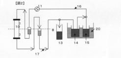
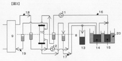
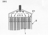
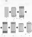
- Sectional drawing of an example of the adsorption column of this invention A circuit for measuring ⁇ 2 -MG clearance. Circuit for measuring ⁇ 2 -MG clearance in an artificial kidney module. Sectional drawing of the module of the hemodialyzer used by the comparative examples 3 and 4. FIG. Sectional drawing of the upper part of the adsorption column whose partition is a mesh. Sectional drawing which shows the manufacturing process of the adsorption column whose partition is a potting material.
- the present invention has the configuration as described in the above section for solving the problems.
- the feature of (1) described in the section for solving the problem is that the treatment liquid such as blood and blood components flowing from the column inlet flows both inside and outside the hollow fiber membrane,
- the basic constitution of the adsorption column according to the present invention is evaluated.
- the feature (2) described in the section for solving the problem is that a hollow fiber membrane having a porous structure is useful as an adsorption carrier in the adsorption column. It is a structural condition of the column for the substance to be adsorbed from the treatment liquid to be adsorbed to the hollow fiber membrane by the diffusion phenomenon, and it is a structural condition of the column. In particular, efficient removal of ⁇ 2 -MG is achieved. In addition, cytokines, autoantibodies, etc. can be removed efficiently.
- the feature of (3) shown in the column of means for solving the problem is that the treatment liquid flows both inside and outside the hollow fiber membrane, and the structure inside and outside the hollow fiber membrane and the flow of the treatment liquid in the column Is focused on.
- the ratio of the pressure loss inside and outside the hollow fiber membrane affects the distribution ratio of the flow rate of the treatment liquid inside and outside the hollow fiber membrane.
- the pressure loss inside the hollow fiber membrane can be controlled by adjusting the inner diameter and length of the hollow fiber membrane, the filling rate of the hollow fiber membrane in the case, and the like.
- the adsorption column of the present invention has a bundle of hollow fibers built in the case.
- the case has headers at both ends, and is provided with a processing liquid inlet at one end of the header and a processing liquid outlet at the end of the other header.
- a processing liquid inlet at one end of the header
- a processing liquid outlet at the end of the other header.
- the former when processing a body fluid such as blood, the former may be referred to as a blood side inlet (Bi) and the latter as a blood side outlet (Bo).
- a partition is partitioned between one header and a bundle of hollow fiber membranes, and another header and a bundle of hollow fiber membranes.
- the partition wall has a plurality of holes for allowing a part of the treatment liquid to communicate with the inside of the hollow fiber membrane and a plurality of holes for allowing the remainder of the treatment liquid to communicate with the outside of the hollow fiber membrane.
- the hole may have a structure that allows the treatment liquid to communicate both inside and outside the hollow fiber membrane.
- the bundle of hollow fiber membranes is preferably fixed directly or indirectly to the case, and more preferably indirectly fixed to the case via the partition wall.
- the hollow fiber membrane being porous is an element that affects the adsorption of the substance to be adsorbed.
- the adsorbed substance does not enter the pores, so that the adsorption efficiency tends to decrease.
- the pore diameter is too large, the adsorbed substance is not adsorbed in the void portion, so that the adsorption efficiency tends to decrease.
- the average pore diameter (radius) of the hollow fiber membrane is 7 to 50 nm, it is possible to adsorb low-molecular substances and substances such as proteins and lipid aggregates such as proteins and low-density lipoproteins.
- the removal target is a molecule smaller than ⁇ 2 -MG
- the pore diameter is preferably smaller, and when the molecule is larger than ⁇ 2 -MG, the pore diameter is preferably larger.
- the cross-sectional structure perpendicular to the fiber direction of the hollow fiber membrane is preferably a uniform structure from the viewpoint of adsorption efficiency. The method for measuring the adsorption performance of ⁇ 2 -MG will be described later.
- the clearance after 1 hour of circulation when the blood flow rate is 200 mL / min is preferably 50 or more, more preferably 70 or more, and further preferably 90 or more.
- the pore diameter (radius) is obtained by measuring the freezing point depression due to capillary aggregation of water in the pores by differential scanning calorimetry (DSC) measurement.
- DSC differential scanning calorimetry
- the film thickness of the hollow fiber is preferably 25 ⁇ m or more, more preferably 30 ⁇ m or more, further preferably 35 ⁇ m or more, on the other hand 100 ⁇ m or less, more preferably 70 ⁇ m or less, and further preferably 60 ⁇ m or less.
- the surface structure of the hollow fiber membrane is an important factor because it affects the diffusion of the adsorbed substance into the membrane. Furthermore, since the treatment liquid comes into contact with both the inside and outside of the hollow fiber membrane, and the adsorbed substance diffuses into the hollow fiber membrane from both sides, the structure inside the hollow fiber membrane like a hemodialysis membrane. Not only should you be aware of the structure of the outer surface. That is, if the porosity of the membrane surface is small, proteins tend to hardly diffuse into the membrane. On the other hand, when the hole area ratio is too large, the hollow fiber membrane strength tends to decrease.
- the porosity of the surface in the membrane and the outer surface is preferably 1% or more, more preferably 2% or more, and further 4% or more. On the other hand, it is preferably 40% or less, more preferably 30% or less, and further preferably 20% or less.
- the details of the measurement method for the hole area ratio will be described later, but it can be calculated by taking an electron microscope image of the surface of the hollow fiber membrane, performing image processing.
- the hollow fiber membrane preferably has a hydrophobic polymer as a constituent component. This is because the hydrophobic interaction can be expected to adsorb hydrophobic substances such as proteins. However, if the hydrophobicity is too strong, the protein may not be diffused inside the membrane, but may be adsorbed and deposited on the membrane surface to block the pores. Therefore, when the polymer is formed into a film, the contact angle of water is preferably 40 ° or more, more preferably 50 ° or more, further preferably 60 ° or more, while 120 ° or less is preferable, and 110 ° or less is preferable. The angle is preferably 100 ° or less, and more preferably 90 ° or less.
- hydrophobic polymer examples include polysulfone-based polymers, polyarylate, polycarbonate, ester group-containing polymers such as polymethyl methacrylate and cellulose acetate-based polymers, polystyrene, polypropylene, and polyacrylonitrile.
- polysulfone polymers examples include polysulfone, polyethersulfone, and polyallyl ether.
- ester group-containing polymers include polymethyl methacrylate and cellulose acetate polymers.
- Cellulose acetate polymers include cellulose diacetate, which is a derivative of cellulose. There is cellulose triacetate.
- the ionic group or the hydrophilic group has an effect of imparting appropriate hydrophilicity to the hollow fiber membrane and preventing the pores from being blocked by adhesion to the membrane surface.
- a method for controlling the surface structure and pore diameter of the hollow fiber membrane a method utilizing a phenomenon in which a polymer phase separates from a polymer solution that is a raw material at the time of spinning is used.
- Methods using phase separation can be broadly classified into induced phase separation methods and non-solvent induced separation methods, and which method is suitable depends on the type of polymer and the range of desired pore sizes.
- the following method is exemplified as an overview of the manufacturing process of the hollow fiber membrane.
- a stock solution for spinning in which a polymer is dissolved in a solvent is prepared.
- the stock solution for spinning is discharged from the double tube annular slit die.
- an injection liquid or gas is put inside the hollow fiber membrane.
- it is guided to a coagulation bath after passing through an aerial part (dry part) controlled to a constant atmosphere.
- an aerial part dry part controlled to a constant atmosphere.
- a polymer having an ester bond is preferably used, and among them, polymethyl methacrylate is preferably used. If the hydrophobicity is too strong, an adsorbed substance such as a protein may be adsorbed on the surface of the film before diffusing into the film to form a fouling layer, and the inside of the film may not be effectively used for adsorption. Therefore, a certain degree of hydrophilicity is also important as a membrane material, and an ester bond as a polar group is effective for imparting such a hydrophilic-hydrophobic balance to the membrane surface.
- a polymer having a repeating unit molecular weight of 110 and one ester group, such as polymethyl methacrylate, is preferable because it has a good balance between hydrophilicity and hydrophobicity.
- the ester group is preferably in the polymer side chain rather than the polymer main chain.
- the inner surface structure can be controlled by putting an injection liquid or gas inside the hollow fiber.
- the injection liquid includes a solvent in which the spinning dope can be dissolved, a coagulant such as water or alcohol, a mixture thereof, or a hydrophobic liquid that is a non-solvent of a polymer or mixture thereof soluble in these, for example, , N-octane, aliphatic hydrocarbons such as liquid paraffin, and fatty acid esters such as isopropyl myristate can also be used.
- a gas in addition to an inert gas such as nitrogen gas or argon gas, carbon dioxide or air can be used.
- cooling gas is blown from the outside to the outside of the hollow fiber.
- the cooling gas preferably has a dry bulb temperature of 5 to 20 ° C., more preferably 8 to 17 ° C.
- the dew point which is a measure of the water content, is preferably 0 to 20 ° C., more preferably 5 to 15 ° C.
- the outer atmosphere has a great influence on the outer surface structure.
- the cold air is preferably applied from the direction perpendicular to the yarn. Further, the flow rate of cold air is preferably 3 to 10 m / second, more preferably 6 to 8 m / second.
- the time for the discharged yarn to pass through the dry part is preferably 0.01 to 2 seconds, more preferably 0.1 to 1 second.
- the draft rate at the time of discharge is a parameter defined as the ratio of the speed of the film-forming stock solution exiting from the spinneret and the take-up speed of the produced hollow fiber membrane.
- this draft rate is large, the pores of the membrane are pulled. It is elongated to be elliptical and has a smaller surface area per space than spherical pores.
- the draft rate is preferably 1.5 to 30, and more preferably 3 to 20.
- the discharged yarn is guided to a coagulation bath containing a liquid mainly composed of water, and solidified and desolvated.
- the pore diameter can be increased.
- the coagulation bath temperature is preferably 40 ° C or higher, more preferably 42 ° C or higher, while 55 ° C or lower is preferable, Furthermore, 48 degrees C or less is preferable.
- the size of the pore diameter can be uniformly controlled.
- the concentration of a good solvent other than water is preferably 1 to 40% by weight, more preferably 10 to 30% by weight.
- the time that the yarn is immersed in the coagulation bath is preferably 0.01 to 2 seconds, and more preferably 0.1 to 1 second.
- the means for washing the hollow fiber membrane is not particularly limited, but a method of allowing the hollow fiber membrane to pass through a multi-staged water bath (water washing bath) is preferably used.
- the temperature of the water in the water washing bath is preferably 30 to 50 ° C. from the viewpoint of washing efficiency.
- a step of applying a moisturizing component preferably after the water washing step.
- moisturizing ingredients include glycerin and its aqueous solutions.
- the hollow fiber membrane in order to enhance the dimensional stability of the highly shrinkable hollow fiber membrane, can be passed through a heated bath filled with an aqueous solution of a moisturizing component. It is performed after the process and the moisturizing process.
- the heat treatment bath is filled with a heated aqueous solution of a moisturizing component, and when the hollow fiber membrane passes through the heat treatment bath, it contracts due to a thermal action. If it does so, it will become difficult to shrink
- the heat treatment temperature at this time is preferably 75 ° C. or higher, more preferably 83 ° C. or higher, while 90 ° C. or lower is preferable, and 86 ° C. or lower is set as a more preferable temperature. And the obtained hollow fiber is wound up.
- the hollow fiber membrane is cut into a required length, bundled in a necessary number, and then inserted into a cylindrical hollow fiber membrane case which is a constituent part of the adsorption column.
- the hollow fiber membrane case is preferably made of plastic and transparent.
- the treatment liquid flowing from the treatment liquid introduction part can directly contact the inner surface and the outer surface of the hollow fiber membrane.
- the case of attaching the header to both ends of the hollow fiber membrane case is the case of the adsorption column.
- the partition which divides a hollow fiber membrane and a header part is provided.
- the first is a method in which a mesh 21 is disposed on the end face of the bundle of hollow fibers 1 as shown in FIG.
- the treatment liquid flows as shown by the arrows in FIG.
- part of the mesh opening corresponds to a hole for external circulation.
- Mean average diameter R P of the external circulation hole is the average value of the equivalent diameter (diameter of the area of the same circle as the area of the mesh) of sieve opening portion.
- the value of R P is less than twice the outer diameter of the hollow fiber membrane, preferably not more than 1.2 times, extra-column through a hollow fiber membrane mesh opening portion when it is passed through the processing solution.
- the second is a method of using a potting material as a partition wall.
- a potting material as a partition wall.
- a manufacturing method will be described with reference to FIG.
- the hollow fibers are bundled as shown in FIG. 6-A.
- FIG. 6-B the bundle of hollow fibers is inserted into the case having the potting material injection port 24.
- a plurality of columnar pins 26 for forming communication holes are inserted into both ends of the bundle of hollow fibers, and caps 25 are attached to both ends of the hollow fiber membrane case. Then, it is attached to a centrifuge, and the potting material is injected from the potting material injection port. As shown in FIG. 6-D, the potting material is collected at both cap ends by centrifugation. After the potting material is cured, the cap and pin are removed as shown in FIG. 6-E. As shown in FIG. 6-F, the end of the cured potting material is cut off together with the hollow fiber. Then attach the header as shown in FIG. 6-G. The potting material injection port is sealed.
- a treatment liquid channel is formed between the header portion and the inside of the hollow fiber membrane and between the header portion and the outside of the hollow fiber membrane.
- the diameter about a smaller hole is employ
- an adsorption column can be obtained by attaching a header having a treatment liquid introduction part and a header having a treatment liquid lead-out part to both ends of the case.
- the adsorption efficiency of the substance to be adsorbed to the hollow fiber membrane decreases when the treatment liquid flows preferentially either inside or outside the hollow fiber membrane.
- the flow of the processing liquid to the inside and outside of the hollow fiber membrane depends on the inner diameter, outer diameter and number of hollow fiber membranes incorporated in the case and the inner diameter of the hollow fiber membrane case.
- the pressure loss of the circular tube can be calculated from the Hagen-Poiseuille equation.
- the inner diameter of the hollow fiber membrane is R i (cm)
- the outer diameter of the hollow fiber membrane is R o (cm)
- the length of the hollow fiber membrane is L (cm)
- the number of hollow fiber membranes is N
- the hollow fiber membranes When the inner diameter of the case is R (cm), the partition wall thickness is 1 (cm), the average diameter of the external circulation holes is R P (cm), and the number of external circulation holes is n, the pressure loss (inside the hollow fiber membrane)
- the unit Pa) is given by Equation 1 below.
- ⁇ A ⁇ L / (N ⁇ Ri 4 ) Equation 1
- a (Pa ⁇ mL) is a coefficient depending on the flow rate of the processing liquid at the inlet and the viscosity of the processing liquid.
- the pressure loss (unit Pa) outside the hollow fiber membrane is given by the following mathematical formula 2.
- ⁇ A ⁇ ⁇ L ⁇ (R + N ⁇ R o ) 2 / (R 2 ⁇ N ⁇ R o 2 ) 3 + l / (n ⁇ R P 4 ) ⁇ Equation 2
- Equation 2 the 1 / (n ⁇ R P 4 ) term in Equation 2 can be ignored.
- the mesh openings of the mesh are arranged almost uniformly on the inner side and the outer side of the hollow fiber.
- the 1 / (n ⁇ R P 4 ) term is negligible.
- the 1 / (n ⁇ R P 4 ) term of Equation 2 is calculated.
- ⁇ is a parameter related to pressure loss inside the hollow fiber membrane
- ⁇ is a parameter related to pressure loss outside the hollow fiber membrane.
- ⁇ / ⁇ is preferably greater than 0.15, and more preferably greater than 0.2, while ⁇ / ⁇ is less than 2, preferably less than 1.8, and more preferably less than 1.5. .
- ⁇ / ⁇ should be close to 1 from the viewpoint of the flow of the processing liquid.
- the substance to be adsorbed is ⁇ 2 -MG, it has been found that sufficient adsorption removal property is obtained even in a range larger than 0.2 and smaller than 0.6.
- residual blood The phenomenon in which blood remains in the column when the operation of returning the blood in the column or circuit back to the body using physiological saline after extracorporeal circulation treatment is called residual blood.
- residual blood As a cause of residual blood, blood may remain due to poor flow of physiological saline in the column.
- the blood coagulation system is activated, blood viscosity increases, and blood may remain.
- ⁇ / ⁇ is preferably 0.15 or more and 1.5 or less.
- the outside of the hollow fiber membrane is often damaged when spinning, winding, or inserting a yarn bundle.
- the blood coagulation system is activated by stimulating platelets and leukocytes, and blood cell components adhere to the site, causing residual blood It can be a cause. That is, it is preferable to reduce the roughness of a portion that comes into contact with the yarn, such as a roller or a guide for guiding the yarn.
- the threads on the outer periphery may be twisted.
- the inner side of the hollow fiber membrane is not significantly affected, but the bundle of hollow fiber membranes is not affected.
- the blood returnability at the outer periphery is poor.
- the yarn whose hollow fiber membrane insertion angle is 10 ° or more with respect to the column longitudinal direction is 10% or less, more preferably 5% of the number of yarns on the outer peripheral portion.
- the outer peripheral yarn refers to a yarn whose presence can be confirmed visually from the side of the column.
- the surface center line average roughness (Ra) is preferably 0.1 ⁇ m or more, more preferably 0.2 ⁇ m or more, and on the other hand, 5 ⁇ m or less, and more preferably 2 ⁇ m or less, as surface irregularities.
- the obtained spinning dope was discharged into air from a double tube hollow fiber membrane die having an outer diameter / inner diameter of 2.1 / 1.95 mm ⁇ of an annular slit portion kept at 96 ° C.
- the hollow fiber inner diameter, outer diameter, and coagulation bath temperature were spun under various conditions described in Table 1.
- glycerin is added as a 63% by weight aqueous solution as a moisturizing agent, and after a heat treatment step of 83 ° C., excess glycerin is removed with a scraper and wound up to obtain a hollow fiber membrane It was.
- both ends were fixed and heated.
- the PMMA hollow fiber membrane shrinks due to heat, but by fixing both ends, tension is applied and the hole diameter increases.
- the following method is used. A bundle of hollow fiber membranes is assembled in the case, and both ends are fixed with a potting material. The bundle of hollow fiber membranes is washed with water and stored in water at 40 ° C. for 2 weeks.
- the hollow fiber membrane was cut out, bundled and inserted into the hollow fiber case 2 shown in FIG. 1, and an adsorption column was prepared by attaching a grid-like mesh 21 having an opening of 247 ⁇ m and a wire diameter (thickness) of 71 ⁇ m and a header 22. .
- the mesh and the hollow fiber membrane were not bonded.
- an O-ring 23 is interposed between the hollow fiber membrane case 2 and the header 22.
- the length L of the hollow fiber was 21 cm.
- the inner and outer surfaces of the hollow fiber membrane were observed with a field emission type scanning electron microscope (S800 manufactured by Hitachi, Ltd.) at a magnification of 1000 times. At this time, the brightness and contrast of the image used the automatic function of the apparatus. Next, the hole portion was painted black using Microsoft (registered trademark) Paint (Microsoft Ltd.). After binarization, Matrox Inspector 2.2 (Matrox Electronic Systems Ltd.) is used to perform image processing that inverts the hole part white and other parts black. The total opening area was determined, and the opening ratio was calculated. In addition, even when the whole hole is not shown and the end is cut off, a portion that is shown in the image is a calculation target.
- ⁇ 2 -MG is known to be a causative protein of dialysis amyloidosis, which is a long-term dialysis complication.
- Bovine blood added with disodium ethylenediaminetetraacetate was prepared by adding bovine plasma and physiological saline so that the hematocrit was 30 ⁇ 3% and the total protein amount was 6.5 ⁇ 0.5 g / dL.
- ⁇ 2 -MG concentration was added to the bovine blood so as to be 1 mg / l, followed by stirring.
- the cow blood was divided into 2 L for circulation and 1.5 L for clearance measurement.
- the circuit was set as shown in FIG.
- the flow rate was 200 mL / min, and after 2 minutes from the start of the Bi pump 11, 10 ml of a sample was taken from the cow blood 15 for clearance measurement at 37 ° C. and used as Bi solution. After 4 minutes and 30 seconds from the start, 10 ml of the liquid flowing out from the Bo circuit 17 was collected and used as Bo liquid. These samples were stored in a freezer below -20 ° C.
- the clearance was calculated from the ⁇ 2 -MG concentration of each solution according to the following Equation 3. Since measured values may differ depending on the lot of bovine blood, bovine blood of the same lot was used in all of the examples and comparative examples.
- Co (ml / min) (CBi ⁇ CBo) ⁇ Q B / CBi Formula 3
- CO is ⁇ 2 -MG clearance (ml / min)
- CBi is ⁇ 2 -MG concentration of bovine blood entering Bi (mg / mL)
- CB o is ⁇ 2 -MG of bovine blood exiting Bo concentration (mg / mL)
- Q B is Bi pump flow rate (ml / min).
- the method for measuring ⁇ 2 -MG clearance in the artificial kidney module is as follows.
- TR2000S manufactured by Toray Medical Co., Ltd. was used as an evaluation apparatus.
- TR2000S is an apparatus having the Bi pump 11, the F pump 12, and the dialysis apparatus 9 in FIG.
- Dialysate 9 (Kindary fluid AF2 Fuso Yakuhin Kogyo Co., Ltd.) A solution and B solution were set in the dialyzer 9. Water (RO water) that passed through the reverse osmosis membrane was allowed to flow from the dialysate side toward the blood side. The dialysate concentration was 13 to 15 mS / cm, the temperature was 37 ° C., and the dialysate side flow rate (Q D ) was set to 500 mL / min.
- the water removal rate (Q F ) of the water permeable device was set to 10 mL / (min ⁇ m 2 ). It was put into a beaker containing 2 L of 37 ° C. bovine blood to obtain circulating bovine blood 14.
- the Bi pump 11 was started, 90 seconds of liquid coming out through the Bo circuit 16 was accumulated in the waste container, and was discarded. Immediately after that, the liquid passing through the Bo17 circuit was put in the circulation beaker 14, and the circulation was performed in such a state that the liquid could be communicated from the Bo circuit 17 to the Bi circuit 16, the Bi pump 11, and the hollow fiber membrane module 10.
- the blood flow rate (Q B ) was 200 mL / min.
- the F pump 12 of the dialysis machine was moved and circulated for 1 hour (Q B 200 mL / min, Q D 0 mL / min, Q F 10 mL / (min ⁇ m 2 )). Thereafter, the Bi pump 11 and the F pump 12 were stopped.
- the Bi pump 11 is started by passing the adjusted clearance measuring bovine blood 15 through the Bi circuit 16, the Bi pump 11, the hollow fiber membrane module 10, and the Bo circuit 17, and the liquid discharged from the Bo circuit 17 is discarded. Placed in container 13 and discarded the liquid.
- Dialysate flow Q D (which is incorporated in the dialyzer 9, not shown.) Di pump controls were started (Q B 200mL / min, Q D 500mL / min, Q F 10mL / (min ⁇ m 2 )).
- bovine blood was introduced at a flow rate of 200 mL / min from the blood side outlet under the adsorption column. Heparin was added to the bovine blood, and the hematocrit adjusted to 30% and the total protein amount to 6.5 g / dL was used. After confirming that bovine blood flowed into the upper header through the hollow fiber membrane, the supply of bovine blood was stopped. The adsorption column was turned upside down to allow blood to flow from top to bottom. It was circulated for 1 hour in this state.
- Returned blood was washed by flowing 500 mL from top to bottom at a flow rate of 100 mL / min using physiological saline. Thereafter, the number of residual blood threads remaining in the adsorption column was counted from the appearance of the side surface. When there were 50 or more residual blood yarns, it was judged that the residual blood properties were poor.
- Example 1 An adsorption column was prepared according to “1. Preparation of adsorption column” described above. The coagulation bath temperature in the production of the hollow fiber membrane was 45 ° C. Heat treatment with both ends of the hollow fiber membrane fixed was not performed. The surface area of the hollow fiber membrane and the average pore diameter were measured. An adsorption column was assembled under the conditions shown in Table 1 and tested for ⁇ 2 -MG clearance and residual blood. As shown in Table 1, high ⁇ 2 -MG clearance and good residual blood characteristics were obtained. (Example 2) An adsorption column was prepared according to “1.
- Preparation of adsorption column described above.
- the coagulation bath temperature in the production of the hollow fiber membrane was 47 ° C. Both ends of the hollow fiber membrane were fixed and heat treatment was performed at 40 ° C. for 2 weeks. The surface area of the hollow fiber membrane and the average pore diameter were measured.
- An adsorption column was assembled under the conditions shown in Table 1 and tested for ⁇ 2 -MG clearance and residual blood. As shown in Table 1, high ⁇ 2 -MG clearance and good residual blood characteristics were obtained. (Example 3)
- An adsorption column was prepared according to “1. Preparation of adsorption column” described above.
- the coagulation bath temperature in the production of the hollow fiber membrane was 47 ° C. Both ends of the hollow fiber membrane were fixed and heat treatment was performed at 40 ° C. for 2 weeks.
- Example 4 An adsorption column was assembled under the conditions shown in Table 1 and tested for ⁇ 2 -MG clearance and residual blood. As shown in Table 1, high ⁇ 2 -MG clearance and good residual blood characteristics were obtained. (Example 4) An adsorption column was prepared according to “1. Preparation of adsorption column” described above. The coagulation bath temperature in the production of the hollow fiber membrane was 35 ° C. Heat treatment with both ends of the hollow fiber membrane fixed was not performed. The surface area of the hollow fiber membrane and the average pore diameter were measured. An adsorption column was assembled under the conditions shown in Table 1 and tested for ⁇ 2 -MG clearance and residual blood. The results are as shown in Table 1.
- Example 5 An adsorption column was prepared according to “1. Preparation of adsorption column” described above. The hollow fiber membrane used in Example 1 was used. Using a hollow fiber membrane, an adsorption column was assembled under the conditions shown in Table 1, and tested for ⁇ 2 -MG clearance and residual blood. As shown in Table 1, high ⁇ 2 -MG clearance and good residual blood characteristics were obtained.
- Example 6 An adsorption column was prepared according to “1. Preparation of adsorption column” described above. The hollow fiber membrane used in Example 1 was used. Using a hollow fiber membrane, an adsorption column was assembled under the conditions shown in Table 1, and tested for ⁇ 2 -MG clearance and residual blood. As shown in Table 1, high ⁇ 2 -MG clearance and good residual blood characteristics were obtained. (Example 7) An adsorption column was prepared according to “1. Preparation of adsorption column” described above. The hollow fiber membrane used in Example 1 was used. Using a hollow fiber membrane, an adsorption column was assembled under the conditions shown in Table 1, and tested for ⁇ 2 -MG clearance and residual blood.
- the coagulation bath temperature in the production of the hollow fiber membrane was 45 ° C. Heat treatment with both ends of the hollow fiber membrane fixed was not performed.
- An artificial kidney module was produced using this hollow fiber membrane. That is, 15200 hollow fiber membranes were inserted into a cylindrical case having two dialysate nozzles having an inner diameter of 4 cm and a length of 22 cm. Then, a temporary cap was put on both ends, and the potting agent was put through the dialysate nozzle while rotating the module with a centrifuge. After the potting agent was solidified, both ends were cut so that both ends of the hollow fiber membrane were open. A header was attached to the end surface of the potting to obtain an artificial kidney module shown in FIG. Both sides of the hollow fiber membrane were sufficiently washed with water to remove glycerin. Thereafter, the module was filled with water and sterilized with 25 kGy of ⁇ rays.
- a hollow fiber membrane was cut out from the artificial kidney module, and the open area ratio and average pore diameter of the surface of the hollow fiber membrane were measured.
- ⁇ 2 -MG clearance and residual blood were tested. As shown in Table 1, ⁇ / ⁇ is larger than 2, but the artificial kidney module has no problem in residual blood characteristics because blood flows only inside the hollow fiber membrane.
- the dialysate was allowed to flow and the filtration was applied, blood flowed only inside the hollow fiber membrane, so the ⁇ 2 -MG clearance was low.
- Example 4 An artificial kidney module was prepared using 12800 hollow fiber membranes of Example 4 in the same manner as in Comparative Example 3, washed with water, and sterilized with 25 kGy ⁇ rays. In the artificial kidney module, since blood flows only inside the hollow fiber membrane, there was no problem of residual blood characteristics outside the hollow fiber membrane. However, on the other hand, despite the fact that the dialysate was passed and filtered, blood did not flow outside the hollow fiber membrane, so ⁇ 2 -MG clearance was lower than that in Example 4. . (Comparative Example 5) In the production of the adsorption column 1, the adsorption column was assembled under the conditions shown in Table 1 using the same hollow fiber membrane as in Example 1, and tested for ⁇ 2 -MG clearance and residual blood.
- Example 1 As a result, an adsorption column was assembled under the conditions shown in Table 1 and tested for ⁇ 2 -MG clearance and residual blood. As shown in Table 1, ⁇ / ⁇ was smaller than 0.15 and ⁇ 2 -MG clearance was good, but residual blood characteristics were poor.
- Table 2 The results of Examples 1, 5, and 6 and Comparative Examples 1, 2, and 5 are summarized in Table 2. Examples 1, 5, 6 and Comparative Examples 2 and 5 use the same hollow fiber membrane, but Comparative Example 5 when ⁇ / ⁇ is smaller than 0.15 and Comparison when ⁇ / ⁇ is larger than 2 In Example 2, there were many residual blood threads, and ⁇ 2 -MG clearance was also low.
- Comparative Example 1 uses a thread having a higher pore diameter and a higher hole area on the outer surface of the hollow fiber membrane, and therefore ⁇ 2 -MG clearance has a higher value.
- ⁇ / ⁇ in Comparative Example 1 was the same value as in Comparative Example 2, and the residual blood thread was as high as the same.
- Example 5 and Comparative Examples 2 and 3 use the same hollow fiber membrane. Comparative Example 3 is used as a hemodialyzer, and blood flows only inside the hollow fiber membrane. On the other hand, Comparative Example 2 is used as an adsorption column, and blood flows both inside and outside the hollow fiber membrane. For this reason, the ⁇ 2 -MG clearance was higher in Comparative Example 2. However, in Comparative Example 2, since ⁇ / ⁇ was smaller than 0.15, there were many residual blood threads. In Comparative Example 3, since blood flows only inside the hollow fiber membrane, it is considered that there are few residual blood threads.
- Example 5 by setting ⁇ / ⁇ to 1.75, it is considered that ⁇ 2 -MG clearance higher than those in Comparative Examples 2 and 3 was achieved, and the number of residual blood threads could be reduced. Moreover, about Example 4 and the comparative example 4, it is the same hollow fiber membrane, and is the same number of hollow fiber membranes in a hollow fiber membrane case. In this case, ⁇ 2 -MG clearance higher than that of the hemodialyzer was achieved with less residual blood thread.
- the adsorption column according to the present invention can be suitably used for the purpose of adsorbing and removing proteins such as ⁇ 2 -MG using blood as a treatment liquid, and is not limited to blood, but is also included in body fluids and effluents of living organisms. It is also possible to use it for adsorption removal. Further, by appropriately designing the average pore diameter of the hollow fiber membrane, it can be widely used not only for adsorption removal of proteins but also for adsorption removal of substances to be adsorbed.
Landscapes
- Chemical & Material Sciences (AREA)
- Chemical Kinetics & Catalysis (AREA)
- Analytical Chemistry (AREA)
- Organic Chemistry (AREA)
- Engineering & Computer Science (AREA)
- Manufacturing & Machinery (AREA)
- External Artificial Organs (AREA)
- Separation Using Semi-Permeable Membranes (AREA)
Abstract
La présente invention a pour objectif de traiter le problème de la fourniture d'une colonne d'adsorption présentant des propriétés améliorées d'adsorption d'une substance à adsorber en faisant circuler une solution de traitement à l'intérieur et à l'extérieur d'une membrane en mettant en œuvre une membrane capillaire. Afin de résoudre ledit problème, la présente invention concerne une colonne d'adsorption dans laquelle un faisceau de membranes capillaires est intégré dans une gaine, et une unité d'introduction de solution de traitement et une unité d'extraction de solution de traitement sont fournies aux deux extrémités de la gaine, la colonne d'adsorption ayant une structure dans laquelle la solution de traitement en circulation à partir de l'unité d'introduction de solution de traitement entre directement en contact avec la surface interne et la surface externe des membranes capillaires, les membranes capillaires ayant une structure poreuse, et l'équation 0,15<β/α<2 étant satisfaite lorsque α=A×L/(N×Ri
4) et β=A×{L×(R+N×Ro)2/(R2-N×Ro
2)3+1/(n×RP
4)}. Dans les équations, Ri représente le diamètre interne des membranes capillaires, Ro représente le diamètre externe, L représente la longueur, N représente le nombre de membranes capillaires, R représente le diamètre interne de la gaine, l représente l'épaisseur d'une paroi de séparation séparant les membranes capillaires et une section de tête, RP représente le diamètre moyen d'un orifice pour la circulation externe, n représente le nombre d'orifices pour la circulation externe, α représente la perte de pression à l'intérieur des membranes capillaires, et β représente la perte de pression à l'extérieur des membranes capillaires.
Applications Claiming Priority (2)
| Application Number | Priority Date | Filing Date | Title |
|---|---|---|---|
| JP2012046246 | 2012-03-02 | ||
| JP2012-046246 | 2012-03-02 |
Publications (1)
| Publication Number | Publication Date |
|---|---|
| WO2013129384A1 true WO2013129384A1 (fr) | 2013-09-06 |
Family
ID=49082581
Family Applications (1)
| Application Number | Title | Priority Date | Filing Date |
|---|---|---|---|
| PCT/JP2013/054936 Ceased WO2013129384A1 (fr) | 2012-03-02 | 2013-02-26 | Colonne d'adsorption |
Country Status (2)
| Country | Link |
|---|---|
| JP (1) | JPWO2013129384A1 (fr) |
| WO (1) | WO2013129384A1 (fr) |
Cited By (5)
| Publication number | Priority date | Publication date | Assignee | Title |
|---|---|---|---|---|
| WO2014126014A1 (fr) * | 2013-02-12 | 2014-08-21 | 東レ株式会社 | Colonne de purification de sang |
| JP2016193178A (ja) * | 2015-03-31 | 2016-11-17 | 東レ株式会社 | 浄化カラム |
| JPWO2017082423A1 (ja) * | 2015-11-11 | 2018-08-30 | 旭化成メディカル株式会社 | 血液処理用リン吸着剤、血液処理システム及び血液処理方法 |
| CN109069963A (zh) * | 2016-03-31 | 2018-12-21 | 恩特格里斯公司 | 喷嘴过滤器 |
| KR20200030041A (ko) * | 2017-12-26 | 2020-03-19 | 주식회사 포스코 | 리튬 흡착제, 및 이를 이용한 리튬 흡착 장치 |
Citations (3)
| Publication number | Priority date | Publication date | Assignee | Title |
|---|---|---|---|---|
| JPH0614996A (ja) * | 1992-05-01 | 1994-01-25 | Kawasumi Lab Inc | 吸着モジュ−ル |
| JP2002504020A (ja) * | 1997-06-14 | 2002-02-05 | アクゾ ノーベル ナムローゼ フェンノートシャップ | 片側を埋め込まれた中空繊維膜を有する膜モジュール |
| WO2009128564A1 (fr) * | 2008-04-18 | 2009-10-22 | 日機装株式会社 | Adsorbant pour l'élimination des érythrocytes |
-
2013
- 2013-02-26 WO PCT/JP2013/054936 patent/WO2013129384A1/fr not_active Ceased
- 2013-02-26 JP JP2013526244A patent/JPWO2013129384A1/ja active Pending
Patent Citations (3)
| Publication number | Priority date | Publication date | Assignee | Title |
|---|---|---|---|---|
| JPH0614996A (ja) * | 1992-05-01 | 1994-01-25 | Kawasumi Lab Inc | 吸着モジュ−ル |
| JP2002504020A (ja) * | 1997-06-14 | 2002-02-05 | アクゾ ノーベル ナムローゼ フェンノートシャップ | 片側を埋め込まれた中空繊維膜を有する膜モジュール |
| WO2009128564A1 (fr) * | 2008-04-18 | 2009-10-22 | 日機装株式会社 | Adsorbant pour l'élimination des érythrocytes |
Cited By (16)
| Publication number | Priority date | Publication date | Assignee | Title |
|---|---|---|---|---|
| US10213543B2 (en) | 2013-02-12 | 2019-02-26 | Toray Industries, Inc. | Blood purification column |
| EP2957306A4 (fr) * | 2013-02-12 | 2016-10-19 | Toray Industries | Colonne de purification de sang |
| WO2014126014A1 (fr) * | 2013-02-12 | 2014-08-21 | 東レ株式会社 | Colonne de purification de sang |
| JP2016193178A (ja) * | 2015-03-31 | 2016-11-17 | 東レ株式会社 | 浄化カラム |
| JPWO2017082423A1 (ja) * | 2015-11-11 | 2018-08-30 | 旭化成メディカル株式会社 | 血液処理用リン吸着剤、血液処理システム及び血液処理方法 |
| KR20210025714A (ko) * | 2016-03-31 | 2021-03-09 | 엔테그리스, 아이엔씨. | 노즐 필터 |
| JP2019509893A (ja) * | 2016-03-31 | 2019-04-11 | インテグリス・インコーポレーテッド | ノズルフィルタ |
| CN109069963A (zh) * | 2016-03-31 | 2018-12-21 | 恩特格里斯公司 | 喷嘴过滤器 |
| JP2021090962A (ja) * | 2016-03-31 | 2021-06-17 | インテグリス・インコーポレーテッド | ノズルフィルタ |
| CN109069963B (zh) * | 2016-03-31 | 2022-02-22 | 恩特格里斯公司 | 喷嘴过滤器 |
| US11338246B2 (en) | 2016-03-31 | 2022-05-24 | Entegris, Inc. | Nozzle filter |
| TWI781926B (zh) * | 2016-03-31 | 2022-11-01 | 美商恩特葛瑞斯股份有限公司 | 噴嘴過濾器 |
| KR102531426B1 (ko) * | 2016-03-31 | 2023-05-12 | 엔테그리스, 아이엔씨. | 노즐 필터 |
| JP7621812B2 (ja) | 2016-03-31 | 2025-01-27 | インテグリス・インコーポレーテッド | ノズルフィルタ |
| KR20200030041A (ko) * | 2017-12-26 | 2020-03-19 | 주식회사 포스코 | 리튬 흡착제, 및 이를 이용한 리튬 흡착 장치 |
| KR102265697B1 (ko) * | 2017-12-26 | 2021-06-15 | 주식회사 포스코 | 리튬 흡착제, 및 이를 이용한 리튬 흡착 장치 |
Also Published As
| Publication number | Publication date |
|---|---|
| JPWO2013129384A1 (ja) | 2015-07-30 |
Similar Documents
| Publication | Publication Date | Title |
|---|---|---|
| US4874522A (en) | Polysulfone hollow fiber membrane and process for making the same | |
| KR102144703B1 (ko) | 중공사막 모듈, 중공사막의 제조 방법 및 중공사막 모듈의 제조 방법 | |
| EP0750938B1 (fr) | Procédé de fabrication d'une membrane semi-perméable à fibres creuses en polysulfone | |
| CN101484235B (zh) | 血浆分离膜 | |
| CN104902941B (zh) | 血液净化柱 | |
| US10994248B2 (en) | Hollow fiber membrane module and manufacturing method thereof | |
| JP6565187B2 (ja) | 多孔質膜、多孔質膜を内蔵する血液浄化用モジュールおよび多孔質膜の製造方法 | |
| JP5857407B2 (ja) | 中空糸膜および中空糸膜の製造方法 | |
| WO2010133612A1 (fr) | Membranes ayant une performance améliorée | |
| Nguyen et al. | Fabrication of hollow fiber membranes with different inner diameters for enhanced uremic toxins removal in hemodialysis: Exploring from high-flux to high molecular weight retention onset classes | |
| US10888823B2 (en) | Membrane with improved permeability and selectivity | |
| JPWO2015125852A1 (ja) | 血小板浮遊液洗浄用の中空糸膜モジュール | |
| JP2009262147A (ja) | ポリスルホン系分離膜およびポリスルホン系分離膜モジュールの製造方法 | |
| JPWO2013129384A1 (ja) | 吸着カラム | |
| JP2017185221A (ja) | 吸着カラム | |
| JP2011092928A (ja) | 分離膜および分離膜モジュール | |
| JP4992104B2 (ja) | 血液濾過または血液濾過透析用のモジュール | |
| JP4923902B2 (ja) | 血液浄化用中空糸膜およびその製造方法 | |
| KR102938290B1 (ko) | 섬유 다발 및 그 제조 방법 및 정화 칼럼 | |
| JPH0970431A (ja) | ポリスルホン系中空糸型人工腎臓の製造方法および人工腎臓 | |
| WO2013047549A1 (fr) | Colonne de purification et procédé de fabrication d'une colonne de purification | |
| JP4381058B2 (ja) | 血液適合性に優れた中空糸型血液浄化器 | |
| JP4093134B2 (ja) | 中空糸型血液浄化膜 | |
| JP2020124273A (ja) | 血液浄化カラム | |
| JP6547518B2 (ja) | 中空糸膜モジュール及びその製造方法 |
Legal Events
| Date | Code | Title | Description |
|---|---|---|---|
| ENP | Entry into the national phase |
Ref document number: 2013526244 Country of ref document: JP Kind code of ref document: A |
|
| 121 | Ep: the epo has been informed by wipo that ep was designated in this application |
Ref document number: 13754447 Country of ref document: EP Kind code of ref document: A1 |
|
| NENP | Non-entry into the national phase |
Ref country code: DE |
|
| 122 | Ep: pct application non-entry in european phase |
Ref document number: 13754447 Country of ref document: EP Kind code of ref document: A1 |