WO2013129430A1 - 断熱部材、及びエンジン燃焼室構造 - Google Patents
断熱部材、及びエンジン燃焼室構造 Download PDFInfo
- Publication number
- WO2013129430A1 WO2013129430A1 PCT/JP2013/055021 JP2013055021W WO2013129430A1 WO 2013129430 A1 WO2013129430 A1 WO 2013129430A1 JP 2013055021 W JP2013055021 W JP 2013055021W WO 2013129430 A1 WO2013129430 A1 WO 2013129430A1
- Authority
- WO
- WIPO (PCT)
- Prior art keywords
- heat insulating
- layer
- insulating member
- porous layer
- combustion chamber
- Prior art date
- Legal status (The legal status is an assumption and is not a legal conclusion. Google has not performed a legal analysis and makes no representation as to the accuracy of the status listed.)
- Ceased
Links
Images



Classifications
-
- F—MECHANICAL ENGINEERING; LIGHTING; HEATING; WEAPONS; BLASTING
- F02—COMBUSTION ENGINES; HOT-GAS OR COMBUSTION-PRODUCT ENGINE PLANTS
- F02F—CYLINDERS, PISTONS OR CASINGS, FOR COMBUSTION ENGINES; ARRANGEMENTS OF SEALINGS IN COMBUSTION ENGINES
- F02F1/00—Cylinders; Cylinder heads
- F02F1/24—Cylinder heads
-
- C—CHEMISTRY; METALLURGY
- C04—CEMENTS; CONCRETE; ARTIFICIAL STONE; CERAMICS; REFRACTORIES
- C04B—LIME, MAGNESIA; SLAG; CEMENTS; COMPOSITIONS THEREOF, e.g. MORTARS, CONCRETE OR LIKE BUILDING MATERIALS; ARTIFICIAL STONE; CERAMICS; REFRACTORIES; TREATMENT OF NATURAL STONE
- C04B41/00—After-treatment of mortars, concrete, artificial stone or ceramics; Treatment of natural stone
- C04B41/009—After-treatment of mortars, concrete, artificial stone or ceramics; Treatment of natural stone characterised by the material treated
-
- C—CHEMISTRY; METALLURGY
- C04—CEMENTS; CONCRETE; ARTIFICIAL STONE; CERAMICS; REFRACTORIES
- C04B—LIME, MAGNESIA; SLAG; CEMENTS; COMPOSITIONS THEREOF, e.g. MORTARS, CONCRETE OR LIKE BUILDING MATERIALS; ARTIFICIAL STONE; CERAMICS; REFRACTORIES; TREATMENT OF NATURAL STONE
- C04B41/00—After-treatment of mortars, concrete, artificial stone or ceramics; Treatment of natural stone
- C04B41/45—Coating or impregnating, e.g. injection in masonry, partial coating of green or fired ceramics, organic coating compositions for adhering together two concrete elements
- C04B41/52—Multiple coating or impregnating multiple coating or impregnating with the same composition or with compositions only differing in the concentration of the constituents, is classified as single coating or impregnation
-
- C—CHEMISTRY; METALLURGY
- C04—CEMENTS; CONCRETE; ARTIFICIAL STONE; CERAMICS; REFRACTORIES
- C04B—LIME, MAGNESIA; SLAG; CEMENTS; COMPOSITIONS THEREOF, e.g. MORTARS, CONCRETE OR LIKE BUILDING MATERIALS; ARTIFICIAL STONE; CERAMICS; REFRACTORIES; TREATMENT OF NATURAL STONE
- C04B41/00—After-treatment of mortars, concrete, artificial stone or ceramics; Treatment of natural stone
- C04B41/80—After-treatment of mortars, concrete, artificial stone or ceramics; Treatment of natural stone of only ceramics
- C04B41/81—Coating or impregnation
- C04B41/89—Coating or impregnation for obtaining at least two superposed coatings having different compositions
-
- F—MECHANICAL ENGINEERING; LIGHTING; HEATING; WEAPONS; BLASTING
- F01—MACHINES OR ENGINES IN GENERAL; ENGINE PLANTS IN GENERAL; STEAM ENGINES
- F01L—CYCLICALLY OPERATING VALVES FOR MACHINES OR ENGINES
- F01L3/00—Lift-valve, i.e. cut-off apparatus with closure members having at least a component of their opening and closing motion perpendicular to the closing faces; Parts or accessories thereof
- F01L3/02—Selecting particular materials for valve-members or valve-seats; Valve-members or valve-seats composed of two or more materials
- F01L3/04—Coated valve members or valve-seats
-
- F—MECHANICAL ENGINEERING; LIGHTING; HEATING; WEAPONS; BLASTING
- F02—COMBUSTION ENGINES; HOT-GAS OR COMBUSTION-PRODUCT ENGINE PLANTS
- F02B—INTERNAL-COMBUSTION PISTON ENGINES; COMBUSTION ENGINES IN GENERAL
- F02B77/00—Component parts, details or accessories, not otherwise provided for
- F02B77/11—Thermal or acoustic insulation
-
- F—MECHANICAL ENGINEERING; LIGHTING; HEATING; WEAPONS; BLASTING
- F02—COMBUSTION ENGINES; HOT-GAS OR COMBUSTION-PRODUCT ENGINE PLANTS
- F02F—CYLINDERS, PISTONS OR CASINGS, FOR COMBUSTION ENGINES; ARRANGEMENTS OF SEALINGS IN COMBUSTION ENGINES
- F02F3/00—Pistons
- F02F3/10—Pistons having surface coverings
- F02F3/12—Pistons having surface coverings on piston heads
-
- F—MECHANICAL ENGINEERING; LIGHTING; HEATING; WEAPONS; BLASTING
- F16—ENGINEERING ELEMENTS AND UNITS; GENERAL MEASURES FOR PRODUCING AND MAINTAINING EFFECTIVE FUNCTIONING OF MACHINES OR INSTALLATIONS; THERMAL INSULATION IN GENERAL
- F16J—PISTONS; CYLINDERS; SEALINGS
- F16J1/00—Pistons; Trunk pistons; Plungers
- F16J1/01—Pistons; Trunk pistons; Plungers characterised by the use of particular materials
-
- F—MECHANICAL ENGINEERING; LIGHTING; HEATING; WEAPONS; BLASTING
- F28—HEAT EXCHANGE IN GENERAL
- F28F—DETAILS OF HEAT-EXCHANGE AND HEAT-TRANSFER APPARATUS, OF GENERAL APPLICATION
- F28F13/00—Arrangements for modifying heat-transfer, e.g. increasing, decreasing
-
- F—MECHANICAL ENGINEERING; LIGHTING; HEATING; WEAPONS; BLASTING
- F01—MACHINES OR ENGINES IN GENERAL; ENGINE PLANTS IN GENERAL; STEAM ENGINES
- F01L—CYCLICALLY OPERATING VALVES FOR MACHINES OR ENGINES
- F01L2301/00—Using particular materials
- F01L2301/02—Using ceramic materials
-
- F—MECHANICAL ENGINEERING; LIGHTING; HEATING; WEAPONS; BLASTING
- F01—MACHINES OR ENGINES IN GENERAL; ENGINE PLANTS IN GENERAL; STEAM ENGINES
- F01L—CYCLICALLY OPERATING VALVES FOR MACHINES OR ENGINES
- F01L2303/00—Manufacturing of components used in valve arrangements
-
- F—MECHANICAL ENGINEERING; LIGHTING; HEATING; WEAPONS; BLASTING
- F01—MACHINES OR ENGINES IN GENERAL; ENGINE PLANTS IN GENERAL; STEAM ENGINES
- F01L—CYCLICALLY OPERATING VALVES FOR MACHINES OR ENGINES
- F01L2810/00—Arrangements solving specific problems in relation with valve gears
- F01L2810/01—Cooling
-
- F—MECHANICAL ENGINEERING; LIGHTING; HEATING; WEAPONS; BLASTING
- F01—MACHINES OR ENGINES IN GENERAL; ENGINE PLANTS IN GENERAL; STEAM ENGINES
- F01L—CYCLICALLY OPERATING VALVES FOR MACHINES OR ENGINES
- F01L2820/00—Details on specific features characterising valve gear arrangements
- F01L2820/01—Absolute values
-
- F—MECHANICAL ENGINEERING; LIGHTING; HEATING; WEAPONS; BLASTING
- F05—INDEXING SCHEMES RELATING TO ENGINES OR PUMPS IN VARIOUS SUBCLASSES OF CLASSES F01-F04
- F05C—INDEXING SCHEME RELATING TO MATERIALS, MATERIAL PROPERTIES OR MATERIAL CHARACTERISTICS FOR MACHINES, ENGINES OR PUMPS OTHER THAN NON-POSITIVE-DISPLACEMENT MACHINES OR ENGINES
- F05C2251/00—Material properties
- F05C2251/04—Thermal properties
- F05C2251/048—Heat transfer
Definitions
- the present invention relates to a heat insulating member for improving the thermal efficiency of an engine and improving fuel consumption, and an engine combustion chamber structure.
- the present invention relates to a heat insulating member focused on heat transfer by radiation from a fuel combustion flame to an inner wall constituting an engine combustion chamber, and an engine combustion chamber structure.
- Patent Document 1 aims to supply a film having a low thermal conductivity, a low heat capacity, and excellent durability and reliability that is free from peeling and dropping for use in an engine combustion chamber.
- an anodized film having a film thickness of more than 20 ⁇ m and 500 ⁇ m or less and a porosity of 20% or more is formed on the inner wall constituting the engine combustion chamber. .
- Patent document 2 aims at providing an internal combustion engine provided with the structural member which improved the heat insulation performance.
- a heat insulating material is disposed adjacent to the inner wall of the exhaust passage, and high-temperature working gas (exhaust gas) flows along a flow path formed by the heat insulating material.
- the heat insulating material is laminated in a state where each particle of spherical mesoporous silica particles having an average particle diameter of 0.1 to 3 ⁇ m is densely dissolved through the bonding material.
- the spherical mesoporous silica particles have innumerable mesopores having an average pore diameter of 1 to 10 nm.
- Patent Document 3 discloses that the piston head portion is formed of ceramics to improve engine performance.
- Patent Documents 1 and 2 try to realize low thermal conductivity and low heat capacity by forming a porous material on the inner wall of the engine combustion chamber in order to improve the thermal efficiency of the engine.
- the inner wall of the engine combustion chamber is porous, radiant heat transfer from the combustion flame cannot be suppressed (permeated), and heat may be easily transmitted to the engine component.
- the fuel injected into the engine combustion chamber is absorbed by the porous inner wall, and a normal combustion reaction may not occur.
- the fuel may block the pores.
- Japanese Patent Application Laid-Open No. H10-228707 describes that the pore opening is sealed with a dense layer on the outermost surface of the anodized film.
- the dense layer is preferably thin from the viewpoint of low heat transfer and low volume heat capacity, and it is described that there is no difference in thermal characteristics even when the opening is sealed.
- Patent Document 3 although the ceramic piston head is mechanically fixed, it does not have a function for improving thermal efficiency such as low thermal conductivity.
- An object of the present invention is to provide a heat insulating member and an engine combustion chamber structure for improving the thermal efficiency of an engine and improving fuel consumption.
- the present inventors provide a heat insulating member comprising a heat insulating member including a substrate, a surface dense layer having a porosity of 5% or less, and a heat insulating porous layer having a porosity larger than the porosity of the surface dense layer.
- the present inventors have found that the above problems can be solved. That is, according to the present invention, the following heat insulating member and engine combustion chamber structure are provided.
- the surface dense layer is a heat insulating member having a porosity of 5% or less, and the heat insulating porous layer has a porosity larger than the porosity of the surface dense layer.
- the heat insulating performance of the engine combustion chamber can be improved and fuel consumption can be improved. Since the surface dense layer and the heat insulating porous layer are formed on the substrate, it is possible to perform the film forming process at a high temperature. Moreover, since the surface dense layer and the heat insulating porous layer are supported by the substrate, it is easy to attach to the engine combustion chamber.
- the surface dense layer is a dense layer having a porosity of 5% or less, it is possible to reflect radiation and suppress the absorption of fuel and the adhesion of burning residue.
- a porous heat-insulating porous layer below the surface dense layer, heat transfer to the engine component can be suppressed. Therefore, the durability of the engine constituent members constituting the engine combustion chamber is also improved.
- the heat insulating member 1 includes a substrate 5 made of ceramics, a heat insulating porous layer 3 formed of ceramics on the surface of the substrate 5, and a surface of the heat insulating porous layer 3 made of ceramics. And the formed surface dense layer 2.
- the surface dense layer 2 has a porosity of 5% or less. Further, the heat insulating porous layer 3 has a porosity larger than that of the surface dense layer 2.
- the bonding layer 4 is a layer for bonding the respective layers provided between the surface dense layer 2 and the heat insulating porous layer 3 and between the substrate 5 and the heat insulating porous layer 3. That is, the first bonding layer 4 a is provided between the heat insulating porous layer 3 and the surface dense layer 2. Further, a second bonding layer 4 b is provided between the substrate 5 and the heat insulating porous layer 3. A configuration without the bonding layer 4 can also be adopted.
- the engine combustion chamber structure of the present invention includes the heat insulating member 1 on at least one surface of the piston 14, the valve heads 16s and 17s, and the cylinder head 13.
- the heat insulation performance of the engine combustion chamber 20 can be improved.
- the heat insulating porous layer 3 can suppress heat transfer from the surface dense layer 2 to the engine constituent member 21. For this reason, at the time of fuel combustion, the temperature of the inner wall of the engine constituent member 21 (the wall surface constituting the engine combustion chamber 20) easily rises following the gas temperature of the engine combustion chamber 20.
- FIG. 3 is a diagram showing the gas temperature in the engine combustion chamber 20 and the temperature of the inner wall of the engine component 21.
- the horizontal axis is the crank angle of the engine 10 and corresponds to time.
- the vertical axis is temperature.
- the temperature of the inner wall that does not include the heat insulating member 1 greatly deviates from the gas temperature of the engine combustion chamber 20.
- the temperature of the inner wall provided with the heat insulating member 1 tends to rise following the gas temperature in the engine combustion chamber 20.
- heat loss can be reduced and overheating of the intake air can be prevented. This will be described in more detail below.
- the substrate 5 serves as a support that supports the surface dense layer 2 and the heat insulating porous layer 3.
- the substrate 5 preferably has a thickness of 1 to 30 mm (thickness of a portion having a planar spread; see FIGS. 1, 4A and 4B). If the thickness is about this level, the strength can be sufficient as a supporting substrate, and the heat insulating porous layer 3 and the surface dense layer 2 can be easily formed on the substrate 5.
- the substrate 5 preferably has a four-point bending strength (JIS R1601) of 20 MPa or more. That is, the substrate 5 has sufficient mechanical strength to exist independently.
- the substrate 5 can be formed of ceramics, and examples thereof include zirconia, alumina, silica, mullite, spinel, cordierite, aluminum titanate, titania, silicon nitride, silicon carbide, zinc oxide, and glass.
- the substrate 5 can be manufactured using a press molding method, an injection molding method, a casting molding method, an extrusion molding method, or the like, which is known as a ceramic molding method.
- the substrate 5 should be manufactured using a gel cast method.
- it is possible to obtain a shape that matches the shape of the piston 14 to be joined.
- it may be manufactured by processing into a predetermined shape after molding (unfired) or after firing.
- the heat insulating porous layer 3 and the substrate 5 are preferably formed of ceramics having the same or similar composition.
- the same or similar composition means “there is no difference exceeding 5 at% when the abundance of constituent elements is expressed as a percentage of atomic composition”.
- the heat insulating porous layer 3 is a porous ceramic layer and has a porosity higher than that of the surface dense layer 2.
- the porosity of the heat insulating porous layer 3 is preferably 10 to 99%, more preferably 20 to 90%.
- the heat-insulating porous layer 3 preferably has nano-order pores.
- a nano-sized pore means a pore having a pore diameter of 0.1 nm to 500 nm.
- the heat insulating porous layer 3 preferably has a thermal conductivity of 1 W / (m ⁇ K) or less, more preferably 0.5 W / (m ⁇ K) or less, and 0.1 W / (m ⁇ K). Most preferably: Due to the low thermal conductivity, heat transfer from the surface dense layer 2 to the engine component 21 can be suppressed.
- Heat-insulating, porous layer 3 is preferably heat capacity is 2000kJ / (m 3 ⁇ K) or less, further preferably 1000kJ / (m 3 ⁇ K) or less, 100kJ / (m 3 ⁇ K ) or less Most preferably it is. Due to the low heat capacity, the gas temperature in the engine combustion chamber 20 is likely to be lowered after the fuel is exhausted. Thereby, the compression ratio of the engine can be improved.
- the heat insulating porous layer 3 preferably has a Young's modulus of 50 GPa or less. When the Young's modulus is low, thermal stress and thermal shock due to thermal expansion mismatch between the engine component 21 and the surface dense layer 2 can be reduced.
- the heat-insulating porous layer 3 preferably has a thickness of 10 ⁇ m to 1 mm. By making the heat insulation porous layer 3 into this range, the heat insulation effect can be made sufficient.
- the heat insulating porous layer 3 is a ceramic, and for example, zirconia, alumina, silica, mullite, spinel, cordierite, aluminum titanate, titania, silicon nitride, silicon carbide, zinc oxide, glass, or the like can be used. . These are preferably amorphous from the viewpoint of thermal conductivity. Moreover, you may be comprised with these single materials and the mixture of at least 2 or more types of materials may be sufficient. Examples of the mixture include a composite material in which silica-alumina fibers and hollow silica-alumina particles are dispersed in a silica matrix.
- the thermal conductivity can be further reduced by doping the heat insulating porous layer 3 with a heavy metal element, introducing defects in the crystal structure, or making the crystal grain size nano-sized and having many grain boundaries. it can.
- the surface dense layer 2 is a dense ceramic layer formed on the surface of the heat-insulating porous layer 3 having a porous structure.
- the surface dense layer 2 has a porosity of 5% or less, preferably 0.01 to 4%, more preferably 0.01 to 3%.
- radiant heat transfer to the inner wall of the engine combustion chamber 20 can be suppressed immediately after the combustion to the early combustion period, and from the surface dense layer 2 to the exhaust gas at a low temperature in the late combustion to the exhaust process. By radiating the heat, it is possible to prevent the intake gas introduced next from becoming a high temperature.
- the surface dense layer 2 preferably has a reflectivity at a wavelength of 1.5 ⁇ m of greater than 0.5, more preferably a reflectivity at a wavelength of 1 ⁇ m to 2 ⁇ m of greater than 0.5, and a reflectivity at a wavelength of 1 ⁇ m to 2 ⁇ m. More preferably, it is larger than 0.6.
- the surface dense layer 2 preferably has an emissivity at a wavelength of 2.5 ⁇ m of greater than 0.5, more preferably greater than 0.6, and even more preferably greater than 0.7. By having such a reflectance, conduction of heat to the heat insulating porous layer 3 can be suppressed. Moreover, by having such an emissivity, the heated surface dense layer 2 can be easily cooled.
- the surface dense layer 2 preferably has a heat capacity of 3000 kJ / (m 3 ⁇ K) or less, and more preferably 1000 kJ / (m 3 ⁇ K) or less. Due to the low heat capacity (thin film, small volume), the temperature of the inner wall of the engine component easily follows the gas temperature in the engine combustion chamber 20. The temperature difference between the gas temperature and the heat insulating member 1 (surface dense layer 2) is reduced, and cooling loss can be reduced.
- the surface dense layer 2 preferably has a thermal conductivity of 3 W / (m ⁇ K) or less. By setting the thermal conductivity within this range, conduction of heat to the heat insulating porous layer 3 can be suppressed.
- the surface dense layer 2 preferably has a thickness of 20 ⁇ m or less. By setting the thickness within this range, the temperature of the inner wall of the engine component 21 (the wall surface constituting the engine combustion chamber 20) can easily follow the gas temperature of the engine combustion chamber 20.
- the surface dense layer 2 can be formed of ceramics, and examples thereof include zirconia, alumina, silica, mullite, spinel, cordierite, aluminum titanate, titania, silicon nitride, silicon carbide, zinc oxide, and glass. It is done. Moreover, you may be comprised with these single materials and the mixture of 2 or more types of materials may be sufficient.
- the thermal conductivity can be further lowered by doping the surface dense layer 2 with a heavy metal element, introducing defects in the crystal structure, or making the crystal grain size nano-sized and having many grain boundaries. .
- the bonding layer 4 (first layer) is interposed between the surface dense layer 2 and the heat insulating porous layer 3. It may be configured to have one bonding layer 4a). Moreover, you may comprise so that it may have the joining layer 4 (2nd joining layer 4b) between the board
- the bonding layer 4 preferably has a high thermal resistance, specifically 10 ⁇ 6 to 10 m 2 K / W, more preferably 10 ⁇ 5 to 10 m 2 K / W, and more preferably 10 ⁇ 10 to 10 m 2 K / W. More preferably, it is ⁇ 4 to 10 m 2 K / W.
- a high thermal resistance specifically 10 ⁇ 6 to 10 m 2 K / W, more preferably 10 ⁇ 5 to 10 m 2 K / W, and more preferably 10 ⁇ 10 to 10 m 2 K / W. More preferably, it is ⁇ 4 to 10 m 2 K / W.
- the thermal expansion coefficient of the bonding layer 4 is intermediate between the layers in contact with each other (the first bonding layer 4a is the surface dense layer 2 and the heat insulating porous layer 3, and the second bonding layer 4b is the heat insulating porous layer 3 and the substrate 5). It is preferable to have a thermal expansion coefficient of Further, the Young's modulus of the bonding layer 4 preferably has an intermediate Young's modulus between the layers in contact with each other. Furthermore, it is preferable that the bonding layer 4 has a material composition that suppresses the mutual reaction between the layers in contact with each other. This improves the oxidation resistance and the reaction resistance, and improves the durability of the heat insulating member.
- the bonding layer 4 is preferably a material having an adhesive function or a material that can be formed as a thin film, and examples thereof include an inorganic adhesive, a colloidal solution, a preceramic polymer, a brazing material, and a plating film.
- the heat insulating member 1 is provided on the surface (inner wall) that constitutes the engine combustion chamber 20 of the engine component 21. Specifically, the upper surface 14s of the piston 14, the intake valve 16, the valve heads 16s and 17s of the exhaust valve 17, the bottom surface 13s of the cylinder head 13, and the like can be given.
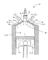
- FIG. 2 is an embodiment showing an engine.
- the engine 10 includes a cylinder block 11 in which a cylinder 12 is formed, and a cylinder head 13 attached so as to cover the upper surface of the cylinder block 11.
- a piston 14 is provided in the cylinder 12 of the cylinder block 11 so as to be slidable in the vertical direction.
- a spark plug 15 is attached to the cylinder head 13.
- an intake valve 16 and an exhaust valve 17 are attached.
- the intake valve 16 is configured to open and close an intake passage 18 formed in the cylinder head 13
- the exhaust valve 17 is configured to open and close an exhaust passage 19.
- the heat insulating member 1 is provided on the upper surface 14 s of the piston 14.
- the substrate 5 is a piston head.
- the heat insulating member 1 is provided on the valve heads 16 s and 17 s of the intake valve 16, the exhaust valve 17, and the bottom surface 13 s of the cylinder head 13. These surfaces are surfaces that form the engine combustion chamber 20, and by providing the heat insulating member 1 on these surfaces, the heat insulating performance can be improved.
- Fuel is supplied to the engine combustion chamber 20 surrounded by the cylinder 12, the cylinder head 13, and the piston 14 by opening the intake valve 16, and is burned by being ignited by the spark plug 15. By this combustion, the piston 14 is pushed down. The exhaust gas generated by the combustion is exhausted by opening the exhaust valve 17.
- the heat insulating member 1 can be fixed to the surface of the engine constituent member 21 constituting the engine combustion chamber 20 by mechanical fixing or chemical fixing.
- mechanical fixing include screwing and fitting.
- chemical fixation include brazing using a brazing material.
- chemical fixing it is not necessary to form screw holes in the substrate 5, and fixing is easy.
- the substrate 5 may be produced by casting together with a piston or the like.
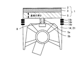
- FIG. 4A shows an embodiment in which the heat insulating member 1 is fixed to the piston 14 by screwing.
- the substrate 5 is a piston head.
- the substrate 5 (piston head) is formed in a disc shape having a convex portion 5a at the center.
- the screw hole 5b is formed in the convex-shaped part 5a. Note that the thickness of the substrate of this embodiment is the thickness of the portion shown in FIG.
- the heat insulating member 1 is placed on the upper surface 14 s of the piston 14, and the screw 8 is inserted into the screw hole 5 b of the convex portion 5 a from the back side of the upper portion of the piston. It can be fixed to the upper surface 14s.
- the heat insulating member 1 is fixed to the upper surface 14s of the piston 14, the heat insulating member 1 is disposed above the piston ring 14r. Therefore, the heat insulating member 1 does not contact the cylinder 12, and it is not necessary to consider friction. Therefore, restrictions on roundness and dimensional accuracy are small.
- FIG. 4B shows another embodiment in which the heat insulating member 1 is fixed to the piston 14 by screwing.
- the convex part 5a is formed in two steps, and the base part of the convex part 5a is formed thicker than the side into which the screw is inserted. That is, in this embodiment, the strength of the convex portion 5a is enhanced and the screw fastening portion is strong.
- the manufacturing method of the heat insulation member 1 is demonstrated.
- the substrate 5 is prepared.
- a slurry containing a ceramic raw material is prepared, formed into a disk shape or a plate shape, and fired to obtain a substrate 5.
- the surface dense layer 2 and the heat insulating porous layer 3 may be formed on the substrate 5 by first forming the heat insulating porous layer 3 and then forming the surface dense layer 2 or simultaneously.
- the heat insulating porous layer 3 can be formed on the substrate 5 by using a porous film forming method such as an EB-PVD method, a thermal spraying method, a CVD method, or a heat treatment after wet coating.
- a porous film forming method in which heat treatment is performed after particles are deposited by electrophoretic deposition, advection accumulation, or the like may be used.
- a porous thin plate may be separately prepared and attached to the substrate 5 with a bonding material.
- the heat insulating porous layer 3 may be formed by applying a paste obtained by adding filler particles (preferably hollow or porous) or a pore former to the binder and kneading them, and curing them, or by heat treatment. Since the heat insulating porous layer 3 is formed on the substrate 5, the firing temperature can be increased. Therefore, the material composition width of the heat insulating porous layer 3 is wide.
- the surface dense layer 2 is formed after the heat insulating porous layer 3 is formed, and after the sputtering method, PVD method, EB-PVD method, CVD method, AD method, thermal spraying, plasma spray method, cold spray method, plating, wet coating. It can be formed by heat treatment or the like. Alternatively, a dense thin plate may be separately prepared as the surface dense layer 2 and attached to the substrate 5 together with the heat insulating porous layer 3.
- the first bonding layer 4 a may be provided between the heat insulating porous layer 3 and the surface dense layer 2, and the second bonding layer 4 b may be provided between the substrate 5 and the heat insulating porous layer 3.
- the bonding layer 4 first bonding layer 4a, second bonding layer 4b
- an inorganic adhesive, a colloidal solution, a preceramic polymer, a brazing material, or the like is applied on the substrate 5.
- the second bonding layer 4b is formed by plating.
- the heat insulating porous layer 3 is formed thereon by the method as described above, the first bonding layer 4a is formed in the same manner as the second bonding layer 4b, and the surface dense layer 2 is formed by the method as described above. be able to.
- the heat insulating member 1 can be manufactured as follows. By forming a ceramic raw material to form a molded body to be the substrate 5, forming a layer to be the heat insulating porous layer 3 and the surface dense layer 2 on the unfired molded body, and integrally sintering them Moreover, the heat insulation member 1 can also be manufactured. Further, a molded body to be the substrate 5 is formed, a layer to be the heat insulating porous layer 3 is molded on the unfired molded body, and these are integrally sintered, and then a layer to be the surface dense layer 2 is molded. Further, the heat insulating member 1 can be manufactured by further sintering.
- Example 1 A piston base material having a shape as shown in FIG. 2 was prepared by aluminum die casting.
- a ceramic piston head (substrate 5) having a convex portion 5a and a screw hole 5b on the back side was prepared as follows so that the piston base and the screw could be fixed.
- a slurry comprising cordierite powder, a dispersant, a gelling agent, a reaction catalyst, and an organic dispersion medium was prepared.
- the slurry was poured into a mold at room temperature, left to stand, and then solidified at 40 ° C. and then released. Further, it was left at room temperature and then at 90 ° C. to obtain a molded body. This was fired at 1430 ° C. to obtain a dense cordierite piston head (substrate 5).
- heat insulating films (a surface dense layer 2 and a heat insulating porous layer 3) were formed on the surface of the piston head as follows. First, a slurry (for the heat-insulating porous layer 3) made of cordierite powder, latex particles as a pore-forming material, a dispersant, a binder, and water is prepared and applied to the surface (upper surface) of the piston head. , And then dried at 90 ° C. Next, a slurry composed of cordierite powder, a dispersant, a binder, and water (for the surface dense layer 2) is prepared, applied to the surface (upper surface) of the piston head, and dried at room temperature and then at 90 ° C. I let you. This was baked at 1380 ° C. to form a heat insulating film on the surface of the cordierite piston head, whereby the heat insulating member 1 was obtained.
- a slurry for the heat-insulating porous layer 3 made of cordierite powder, latex particles as a pore
- the piston 14 was obtained by joining the heat insulating member 1 to the piston base member with a screw and also arranging the piston ring 14r.
- Example 2 Similar to Example 1, a piston base material having a shape as shown in FIG. 2 was prepared.
- a ceramic piston head (substrate 5) having the same shape as in Example 1 was produced as follows. First, a slurry composed of zirconia powder, a dispersant, a gelling agent, a reaction catalyst, and an organic dispersion medium was prepared. The slurry was poured into a mold at room temperature, left to stand, and then solidified at 40 ° C. and then released. Further, it was left at room temperature and then at 90 ° C. to obtain a molded body. This was fired at 1400 ° C. to obtain a dense zirconia piston head (substrate 5).
- heat insulating films (a surface dense layer 2 and a heat insulating porous layer 3) were formed on the surface of the piston head as follows. First, a slurry composed of zirconia powder, melamine resin particles as a pore former, a dispersant, a binder, and water (for the heat insulating porous layer 3) is prepared, and this is applied to the surface (upper surface) of the piston head, Dry at room temperature and then at 90 ° C. Next, a slurry (for the surface dense layer 2) made of zirconia powder, a dispersant, a binder, and water was prepared, applied to the surface (upper surface) of the piston head, and dried at room temperature and then at 90 ° C. . This was baked at 1400 ° C. to form a heat insulating film on the surface of the zirconia piston head, whereby the heat insulating member 1 was obtained.
- the piston 14 was obtained by joining the heat insulating member 1 to the piston base member with a screw and also arranging the piston ring 14r.
- Comparative Example 1 A piston 14 using a piston head (only the substrate 5), which is the same as in Examples 1 and 2, but does not have a heat insulating film formed thereon, is referred to as Comparative Example 1.
- the engine combustion chamber structure of the present invention can be applied to engines such as automobiles.
Landscapes
- Engineering & Computer Science (AREA)
- Chemical & Material Sciences (AREA)
- General Engineering & Computer Science (AREA)
- Ceramic Engineering (AREA)
- Mechanical Engineering (AREA)
- Combustion & Propulsion (AREA)
- Materials Engineering (AREA)
- Structural Engineering (AREA)
- Organic Chemistry (AREA)
- Physics & Mathematics (AREA)
- Acoustics & Sound (AREA)
- Thermal Sciences (AREA)
- Cylinder Crankcases Of Internal Combustion Engines (AREA)
- Combustion Methods Of Internal-Combustion Engines (AREA)
Description
本発明は、エンジンの熱効率を向上させ、燃費を向上させるための断熱部材、及びエンジン燃焼室構造に関する。特に、燃料の燃焼炎からエンジン燃焼室を構成する内壁への輻射による伝熱に注目した断熱部材、及びエンジン燃焼室構造に関する。
エンジンの熱効率を向上させ、燃費を向上させることが望まれている。特許文献1は、エンジン燃焼室に用いるための、低熱伝導・低熱容量であり且つ剥離・脱落等のない耐久性・信頼性に優れた膜を供給することを目的とする。特許文献1では、エンジンの熱効率の向上のために、エンジン燃焼室を構成する内壁に膜厚が20μmより大きく500μm以下であり且つ空孔率が20%以上である陽極酸化被膜を形成している。
特許文献2は、断熱性能を向上させた構造部材を備える内燃機関を提供することを目的とする。特許文献2の内燃機関には、排気通路の内壁に隣接して断熱材が配置され、高温の作動ガス(排気ガス)が、断熱材が形成する流路に沿って流れる。断熱材は、平均粒径が0.1~3μmの球状メソポーラスシリカ粒子の各粒子が接合材を解して密集した状態で積層されている。球状メソポーラスシリカ粒子には、平均孔径1~10nmのメソ孔が無数に形成されている。
特許文献3には、ピストンヘッド部をセラミックスで形成し、エンジン性能の向上を図ることが開示されている。
特許文献1,2のいずれの技術も、エンジンの熱効率を向上させるために、多孔質な材料をエンジン燃焼室の内壁に形成させて、低熱伝導率や低熱容量を実現しようとしている。しかしながら、エンジン燃焼室の内壁が多孔質であると、燃焼炎からの輻射伝熱を抑制できず(透過してしまい)、エンジン構成部材へと熱が伝わりやすくなるおそれがある。また、特に直噴エンジンの場合、エンジン燃焼室内に噴射した燃料は多孔質な内壁に吸収され、正常な燃焼反応が起きない場合がある。特許文献1では燃料が気孔を塞ぐことも起こりうる。
また、燃焼室の内壁が多孔質であると、燃焼後に発生する微量の煤や燃料中の不純物の燃えかすが付着しやすくなる可能性があり、断熱多孔質層の性状が変化し、熱伝導率や熱容量が高くなる恐れがある。特許文献1には、陽極酸化被膜の最表面において、緻密層で空孔の開口部を封じることについての記載がある。しかしながら、低伝熱性、低体積熱容量の観点から緻密層は薄い方が好ましいとされており、開口部を封じても熱特性上の差異は認められないと記載されている。
また、特許文献1,2のいずれの技術も、燃焼ガスの熱がエンジン燃焼室の内壁の最表面に伝わった後、エンジン構成部材の内部へ熱が逃げるのを抑制するために、断熱性の高い膜を形成する。しかし、燃焼ガスの熱がエンジン燃焼室の内壁の最表面に伝わることを抑制する場合に、燃焼炎から内壁の最表面への輻射による伝熱に注目していない。また、エンジン燃焼室の内壁の最表面と、そこに形成される膜とは異種材料であるため、剥離性が問題となる。
一方、特許文献3では、セラミックス製ピストンヘッドを機械的に固定しているが、低熱伝導率などの熱効率向上のための機能は備えていない。
本発明の課題は、エンジンの熱効率を向上させ、燃費を向上させるための断熱部材、及びエンジン燃焼室構造を提供することにある。
本発明者らは、断熱部材が、基板と、気孔率が5%以下の表面緻密層と、表面緻密層の気孔率よりも気孔率が大きい断熱多孔質層とを含む断熱部材を備えることにより、上記課題を解決しうること見出した。すなわち、本発明によれば、以下の断熱部材、及びエンジン燃焼室構造が提供される。
[1] セラミックスにより形成された基板と、前記基板の表面に、セラミックスにより形成された断熱多孔質層と、前記断熱多孔質層の表面に、セラミックスにより形成された表面緻密層と、を含み、前記表面緻密層は、気孔率が5%以下であり、前記断熱多孔質層は、前記表面緻密層の前記気孔率よりも気孔率が大きい、断熱部材。
[2] 前記断熱多孔質層と前記基板は、同一または類似の組成のセラミックスにより形成されている前記[1]に記載の断熱部材。
[3] 前記断熱多孔質層は、ナノオーダーの大きさの気孔を有する前記[1]または[2]に記載の断熱部材。
[4] 前記表面緻密層は、波長1.5μmにおける反射率が、0.5より大きい前記[1]~[3]のいずれかに記載の断熱部材。
[5] 前記表面緻密層は、波長2.5μmにおける輻射率が0.5より大きい前記[1]~[4]のいずれかに記載の断熱部材。
[6] 前記表面緻密層は、厚さが20μm以下である前記[1]~[5]のいずれかに記載の断熱部材。
[7] 前記断熱多孔質層は、熱伝導率が1W/(m・K)以下である前記[1]~[6]のいずれかに記載の断熱部材。
[8] 前記断熱多孔質層は、熱容量が2000kJ/(m3・K)以下である前記[1]~[7]のいずれかに記載の断熱部材。
[9] 前記断熱多孔質層は、厚さが10μm~1mmである前記[1]~[8]のいずれかに記載の断熱部材。
[10] 前記基板は、厚さが1~30mmである前記[1]~[9]のいずれかに記載の断熱部材。
[11] 前記基板は、4点曲げ強度が20MPa以上である前記[1]~[10]のいずれかに記載の断熱部材。
[12] 前記断熱多孔質層と、前記表面緻密層との間に、第一接合層を有する前記[1]~[11]のいずれかに記載の断熱部材。
[13] 前記基板と、前記断熱多孔質層との間に、第二接合層を有する前記[1]~[12]のいずれかに記載の断熱部材。
[14] 前記[1]~[13]のいずれかに記載の断熱部材を、エンジン構成部材のエンジン燃焼室を構成する表面に備えるエンジン燃焼室構造。
[15] 前記断熱部材を、ピストン、バルブヘッド、シリンダヘッドの少なくともいずれかの表面に備える前記[14]に記載のエンジン燃焼室構造。
[16] 前記断熱部材を、前記エンジン構成部材の前記エンジン燃焼室を構成する表面に、機械的固定または化学的固定によって固定した前記[14]または[15]に記載のエンジン燃焼室構造。
[17] 前記機械的固定は、ねじ止め、または嵌め合わせである前記[16]に記載のエンジン燃焼室構造。
[18] 前記化学的固定は、ろう接合である前記[16]に記載のエンジン燃焼室構造。
基板と、表面緻密層と、断熱多孔質層とを含む断熱部材をエンジン燃焼室に用いることにより、エンジン燃焼室の断熱性能を向上させ、燃費を向上させることができる。基板上に、表面緻密層と断熱多孔質層とを成膜するため、高温で成膜プロセスを行うことも可能である。また、基板により表面緻密層と断熱多孔質層とが支持されているため、エンジン燃焼室への取り付けも容易である。
表面緻密層が気孔率5%以下の緻密な層であることにより、輻射を反射するとともに、燃料の吸収や燃えカスの付着を抑制することができる。表面緻密層の下に多孔質な断熱多孔質層を配置することにより、エンジン構成部材への伝熱を抑制することができる。したがって、エンジン燃焼室を構成するエンジン構成部材の耐久性も向上する。
以下、図面を参照しつつ本発明の実施の形態について説明する。本発明は、以下の実施形態に限定されるものではなく、発明の範囲を逸脱しない限りにおいて、変更、修正、改良を加え得るものである。
図1及び図2を用いて本発明の断熱部材1及びエンジン燃焼室構造を説明する。図1に示すように、断熱部材1は、セラミックスにより形成された基板5と、基板5の表面に、セラミックスにより形成された断熱多孔質層3と、断熱多孔質層3の表面に、セラミックスにより形成された表面緻密層2と、を含む。表面緻密層2は、気孔率が5%以下である。また、断熱多孔質層3は、表面緻密層2の気孔率よりも気孔率が大きい。
接合層4は、図1に示すように、表面緻密層2と断熱多孔質層3、基板5と断熱多孔質層3との間に設けられたそれぞれの層を接合するための層である。すなわち、断熱多孔質層3と、表面緻密層2との間に、第一接合層4aを有する。また、基板5と、断熱多孔質層3との間に、第二接合層4bを有する。なお、接合層4がない構成とすることもできる。
本発明のエンジン燃焼室構造は、断熱部材1を、ピストン14、バルブヘッド16s,17s、シリンダヘッド13の少なくともいずれかの表面に備える。
断熱部材1が、緻密な表面緻密層2と、表面緻密層2の下に多孔質な断熱多孔質層3との2層を含むことにより、エンジン燃焼室20の断熱性能を向上させることができる。エンジン燃焼室20内における燃料の燃焼時には、表面緻密層2により輻射を反射し、排気時には、表面緻密層2から熱を放射することができる。また、断熱多孔質層3は、表面緻密層2から、エンジン構成部材21への伝熱を抑制することができる。このため、燃料の燃焼時には、エンジン構成部材21の内壁(エンジン燃焼室20を構成する壁面)の温度が、エンジン燃焼室20のガス温度に追従して上昇しやすくなる。
図3は、エンジン燃焼室20のガス温度とエンジン構成部材21の内壁の温度とを示す図である。横軸は、エンジン10のクランク角度であり、時間に対応する。縦軸は、温度である。断熱部材1を備えない内壁の温度は、エンジン燃焼室20のガス温度と大きく乖離する。一方、断熱部材1を備えた内壁の温度は、エンジン燃焼室20のガス温度に追従して上昇しやすい。このように、内壁の温度が、エンジン燃焼室20のガス温度に追従しやすい場合、熱損失を低減することができるとともに、吸気の過熱を防止することができるようになる。以下、さらに詳しく説明する。
(基板)
基板5は、表面緻密層2と断熱多孔質層3とを支持する支持体となる。基板5は、厚さ(平面的な広がりをもった部分の厚さ。図1,4A,4B参照。)が1~30mmであることが好ましい。厚さがこの程度であれば、支持基材として十分な強度とすることができ、断熱多孔質層3と表面緻密層2を基板5上に形成しやすい。具体的には、基板5は、4点曲げ強度(JIS R1601)が20MPa以上であることが好ましい。つまり、基板5は、自立して存在するに十分な機械的強度を有する。
基板5は、表面緻密層2と断熱多孔質層3とを支持する支持体となる。基板5は、厚さ(平面的な広がりをもった部分の厚さ。図1,4A,4B参照。)が1~30mmであることが好ましい。厚さがこの程度であれば、支持基材として十分な強度とすることができ、断熱多孔質層3と表面緻密層2を基板5上に形成しやすい。具体的には、基板5は、4点曲げ強度(JIS R1601)が20MPa以上であることが好ましい。つまり、基板5は、自立して存在するに十分な機械的強度を有する。
基板5は、セラミックスで形成することができ、例えば、ジルコニア、アルミナ、シリカ、ムライト、スピネル、コーディエライト、アルミニウムチタネート、チタニア、窒化けい素、炭化けい素、酸化亜鉛、ガラスなどが挙げられる。
基板5は、セラミックスの成形方法として知られている、プレス成形法、射出成形法、鋳込み成形法、押出成形法などを用いて製造することができるが、特にゲルキャスト法を用いて製造することにより、接合するピストン14等の形状に合致する形状とすることができる。あるいは、成形後(未焼成)もしくは焼成後に、所定の形状に加工して製造しても良い。
断熱多孔質層3と基板5は、同一または類似の組成のセラミックスにより形成されていることが好ましい。ここで、「同一または類似の組成」とは、「構成元素の存在割合を原子組成百分率で示した際に5at%を越える差異がないこと」を意味する。例えば、基板5が炭化珪素であり、主成分であるSi原子およびC原子と副成分であるO原子の存在割合が、「Si:C:O=50at%:50at%:0at%」であるときについて説明する。この場合、断熱多孔質層3の構成元素の割合が、「Si:C:O=50at%:47at%:3at%」や「Si:C:O=50at%:45at%:5at%」であるならば、類似の組成といえる。一方、「Si:C:O=50at%:43at%:7at%」であるならば、類似の組成とはいえない。断熱多孔質層3と基板5を、同一または類似した組成のセラミックスとすることで、断熱多孔質層3の剥離を抑制することができる。また、熱膨張のミスマッチによる剥離を回避できる。
(断熱多孔質層)
次に、断熱多孔質層3について説明する。断熱多孔質層3は、多孔質のセラミックスの層であり、表面緻密層2の気孔率よりも気孔率が大きい。断熱多孔質層3の気孔率は、10~99%であることが好ましく、20~90%であることがより好ましい。このようにすることにより、表面緻密層2からエンジン構成部材21への熱伝導を抑制することができる。
次に、断熱多孔質層3について説明する。断熱多孔質層3は、多孔質のセラミックスの層であり、表面緻密層2の気孔率よりも気孔率が大きい。断熱多孔質層3の気孔率は、10~99%であることが好ましく、20~90%であることがより好ましい。このようにすることにより、表面緻密層2からエンジン構成部材21への熱伝導を抑制することができる。
断熱多孔質層3は、ナノオーダーの大きさの気孔を有することが好ましい。ここで、「ナノオーダーの大きさの気孔」とは、気孔径が0.1nm以上500nm以下の気孔を意味する。断熱多孔質層3が、ナノオーダーの気孔を有する多孔質層であると、熱伝導率が低く、熱容量も低い。
断熱多孔質層3は、熱伝導率が1W/(m・K)以下であることが好ましく、0.5W/(m・K)以下であることがさらに好ましく、0.1W/(m・K)以下であることが最も好ましい。低熱伝導率であることにより、表面緻密層2からエンジン構成部材21への伝熱を抑制することができる。
断熱多孔質層3は、熱容量が2000kJ/(m3・K)以下であることが好ましく、1000kJ/(m3・K)以下であることがさらに好ましく、100kJ/(m3・K)以下であることが最も好ましい。低熱容量であることにより、燃料の排気後、エンジン燃焼室20内のガス温度を低下させやすい。これにより、エンジンの圧縮比を向上させることができる。
断熱多孔質層3は、ヤング率が50GPa以下であることが好ましい。低ヤング率であると、エンジン構成部材21と表面緻密層2との熱膨張のミスマッチによる熱応力や熱衝撃を緩和することができる。
断熱多孔質層3は、厚さが10μm~1mmであることが好ましい。断熱多孔質層3をこの範囲とすることにより、断熱効果を十分なものとすることができる。
断熱多孔質層3は、セラミックスであり、例えば、ジルコニア、アルミナ、シリカ、ムライト、スピネル、コーディエライト、アルミニウムチタネート、チタニア、窒化けい素、炭化けい素、酸化亜鉛、ガラス等を用いることができる。これらは熱伝導率の観点から非晶質であることが好ましい。また、これらの単一材料で構成されても良いし、少なくとも2種以上の材料の混合物であっても良い。混合物の例として、シリカのマトリックス中にシリカ-アルミナファイバーと中空のシリカ-アルミナ粒子が分散した複合材料などが挙げられる。
また、断熱多孔質層3に重金属元素をドーピングしたり、結晶構造中の欠陥を導入したり、結晶粒径をナノサイズとして粒界を多く存在させることで、さらに熱伝導率を低下させることができる。
(表面緻密層)
表面緻密層2は、多孔質な構造の断熱多孔質層3の表面に形成された緻密なセラミックスの層である。表面緻密層2は、気孔率が5%以下であり、0.01~4%であることが好ましく、0.01~3%であることがより好ましい。このようにすることにより、燃料の燃焼時のガス(燃料)の対流による熱伝達を防止することができる。また緻密なため、燃料の吸収やスス、燃えカスが付着しにくい。
表面緻密層2は、多孔質な構造の断熱多孔質層3の表面に形成された緻密なセラミックスの層である。表面緻密層2は、気孔率が5%以下であり、0.01~4%であることが好ましく、0.01~3%であることがより好ましい。このようにすることにより、燃料の燃焼時のガス(燃料)の対流による熱伝達を防止することができる。また緻密なため、燃料の吸収やスス、燃えカスが付着しにくい。
表面緻密層2は、燃料の燃焼時には、熱源である燃焼炎からの輻射伝熱を抑制する材料で構成される。また、表面緻密層2は、燃料の排気時には、自身の熱を放射しやすいものであることが好ましい。これには、ウイーンの変位則(λmT=2898[μm・K]:ここで、λmは最大放射強度を示す波長、Tは温度を示す。)から予想される波長領域での反射率、輻射率を制御することが望ましい。すなわち、反射率は2μmより小さい波長において大きいことが好ましく、輻射率は2μmより大きい波長において大きいことが好ましい。これにより、燃焼直後~燃焼前期にはエンジン燃焼室20を構成する内壁への輻射伝熱を抑制することができ、また、燃焼後期~排気工程で、低温になると表面緻密層2から排気ガスへと熱を放射することで、次に導入される吸気ガスが高温になることを防止することができる。
表面緻密層2は、波長1.5μmにおける反射率が、0.5より大きいことが好ましく、波長1μm~2μmにおける反射率が0.5より大きいことがより好ましく、波長1μm~2μmにおける反射率が0.6より大きいことがさらに好ましい。表面緻密層2は、波長2.5μmにおける輻射率が0.5より大きいことが好ましく、0.6より大きいことがより好ましく、0.7より大きいことがさらに好ましい。このような反射率を有することにより、断熱多孔質層3への熱の伝導を抑制することができる。また、このような輻射率を有することにより、熱せられた表面緻密層2を冷めやすくすることができる。
表面緻密層2は、熱容量が3000kJ/(m3・K)以下であることが好ましく、1000kJ/(m3・K)以下であることがより好ましい。低熱容量(薄膜、小体積)であることにより、エンジン構成部材の内壁の温度がエンジン燃焼室20内のガス温度に追随しやすくなる。ガス温度と断熱部材1(表面緻密層2)との温度差が小さくなり、冷却損失を低減することができる。
表面緻密層2は、熱伝導率が3W/(m・K)以下であることが好ましい。熱伝導率をこの範囲とすることにより、断熱多孔質層3への熱の伝導を抑制することができる。
表面緻密層2は、厚さが20μm以下であることが好ましい。厚さをこの範囲とすることにより、エンジン構成部材21の内壁(エンジン燃焼室20を構成する壁面)の温度が、エンジン燃焼室20のガス温度に追従しやすくなる。
表面緻密層2は、セラミックスで形成することができ、例えば、ジルコニア、アルミナ、シリカ、ムライト、スピネル、コーディエライト、アルミニウムチタネート、チタニア、窒化けい素、炭化けい素、酸化亜鉛、ガラスなどが挙げられる。また、これらの単一材料で構成されても良いし、2種以上の材料の混合物であっても良い。
また、表面緻密層2に重金属元素をドーピングしたり、結晶構造中の欠陥を導入したり、結晶粒径をナノサイズとして粒界を多く存在させることで、さらに熱伝導率を低下させることができる。
(接合層)
表面緻密層2と断熱多孔質層3とが、直接接合している構成としてもよいが、図1に示すように、表面緻密層2と断熱多孔質層3との間に接合層4(第一接合層4a)を有するように構成してもよい。また、基板5と、断熱多孔質層3との間に、接合層4(第二接合層4b)を有するように構成してもよい。
表面緻密層2と断熱多孔質層3とが、直接接合している構成としてもよいが、図1に示すように、表面緻密層2と断熱多孔質層3との間に接合層4(第一接合層4a)を有するように構成してもよい。また、基板5と、断熱多孔質層3との間に、接合層4(第二接合層4b)を有するように構成してもよい。
接合層4は、熱抵抗が高いことが好ましく、具体的には、10-6~10m2K/Wであることが好ましく、10-5~10m2K/Wであることがより好ましく、10-4~10m2K/Wであることがさらに好ましい。このような接合層4を形成することにより、断熱効果をさらに十分なものとすることができる。また、接合層4を形成することにより、被接合体の熱膨張のミスマッチを緩衝し、耐熱衝撃性・耐熱応力性を向上させることができる。そのために、接合層4の熱膨張係数は、それぞれ接する層(第一接合層4aは表面緻密層2と断熱多孔質層3、第二接合層4bは断熱多孔質層3と基板5)の中間の熱膨張係数を有することが好ましい。また、接合層4のヤング率は、それぞれ接する層の中間のヤング率を有することが好ましい。さらに、接合層4は、それぞれ接する層の相互の反応を抑制するような材料組成とすることが好ましく、これにより、耐酸化性や耐反応性が向上し、断熱部材の耐久性が向上する。
接合層4としては、接着機能を有するもの、あるいは、薄膜として形成させることが可能な材料が好ましく、例えば、無機接着剤、コロイド溶液、プレセラミックポリマー、ろう材、めっき膜などが挙げられる。
(断熱部材の配置)
次に、断熱部材1の配置について説明する。断熱部材1は、エンジン構成部材21のエンジン燃焼室20を構成する表面(内壁)に備えられる。具体的には、ピストン14の上面14s、吸気バルブ16、排気バルブ17のバルブヘッド16s,17s、シリンダヘッド13の底面13s等が挙げられる。
次に、断熱部材1の配置について説明する。断熱部材1は、エンジン構成部材21のエンジン燃焼室20を構成する表面(内壁)に備えられる。具体的には、ピストン14の上面14s、吸気バルブ16、排気バルブ17のバルブヘッド16s,17s、シリンダヘッド13の底面13s等が挙げられる。
図2は、エンジンを示す一実施形態である。エンジン10は、シリンダ12が形成されたシリンダブロック11と、シリンダブロック11の上面を覆って取り付けられたシリンダヘッド13とを有して構成されている。シリンダブロック11のシリンダ12内には、ピストン14が上下方向に摺動可能に備えられている。
シリンダヘッド13には、点火プラグ15が取り付けられている。また、吸気バルブ16、排気バルブ17が取り付けられており、吸気バルブ16は、シリンダヘッド13に形成された吸気通路18を、排気バルブ17は、排気通路19を開閉するように構成されている。
図2に示すように、ピストン14の上面14sに、断熱部材1が備えられている。この場合、基板5は、ピストンヘッドである。また、吸気バルブ16、排気バルブ17のバルブヘッド16s,17s、シリンダヘッド13の底面13sにも同様に、断熱部材1が備えられている。これらの面は、エンジン燃焼室20を形成する面であり、これらの面に、断熱部材1を備えることにより、断熱性能を向上させることができる。
シリンダ12、シリンダヘッド13、ピストン14によって囲まれたエンジン燃焼室20に、吸気バルブ16の開弁により燃料が供給され、点火プラグ15によって点火されることにより、燃焼される。この燃焼により、ピストン14が押し下げられる。燃焼により発生した排気ガスは、排気バルブ17が開弁されることにより排気される。
断熱部材1を、エンジン構成部材21のエンジン燃焼室20を構成する表面に、機械的固定または化学的固定によって固定することができる。機械的固定としては、ねじ止め、嵌め合わせ等が挙げられる。機械的固定を採用すると、断熱部材1が外れにくく、耐久性がある。化学的固定としては、ろう材を用いたろう接合が挙げられる。化学的固定を採用すると、基板5にねじ止めの穴を形成する必要がなく、固定が容易である。あるいは、基板5をピストン等と一緒に鋳込んで作製してもよい。
図4Aに、断熱部材1をピストン14にねじ止めにより固定した実施形態を示す。ピストン14の上面14sに断熱部材1を固定した場合、基板5は、ピストンヘッドである。図4Aに示す実施形態では、基板5(ピストンヘッド)は、中心部に凸状部5aを有する円板形状に形成されている。そして、凸状部5aには、ねじ穴5bが形成されている。なお、本実施形態の基板の厚さは、平面的な広がりをもった、図4Aに示す部分の厚さである。
図4Aに示すように、断熱部材1をピストン14の上面14sに載せ、凸状部5aのねじ穴5bに、ピストンの上部の裏側からねじ8を挿入することにより、断熱部材1をピストン14の上面14sに固定することができる。ピストン14の上面14sに断熱部材1を固定した場合、断熱部材1はピストンリング14rより上に配置するため、断熱部材1がシリンダ12と接触することはなく、摩擦などを考慮する必要はない。したがって、真円度や寸法精度に関する制約が小さい。
図4Bに、断熱部材1をピストン14にねじ止めにより固定した他の実施形態を示す。凸状部5aが2段に形成されており、凸状部5aの付け根部分がねじを挿入する側より、太く形成されている。つまり、本実施形態は、凸状部5aの強度が強化され、ねじ締結部が強い。
(製造方法)
次に、断熱部材1の製造方法について説明する。まず、基板5を用意する。セラミックス原料を含むスラリーを調整し、それを円板状、板状に成形し、焼成して基板5を得る。
次に、断熱部材1の製造方法について説明する。まず、基板5を用意する。セラミックス原料を含むスラリーを調整し、それを円板状、板状に成形し、焼成して基板5を得る。
表面緻密層2および断熱多孔質層3は、基板5の上に、まず、断熱多孔質層3を形成させ、その後、表面緻密層2を形成させても良いし、同時に形成させても良い。
断熱多孔質層3は、EB-PVD法、溶射法、CVD法、湿式コーティング後の熱処理などの多孔質膜の形成法を用いて基板5上に形成することができる。または、電気泳動堆積、移流集積などにより粒子を堆積させた後に熱処理をする多孔質膜の形成法を用いてもよい。あるいは、多孔質な薄板を別途作製して、接合材により基板5に貼り付けてもよい。さらに、結合材にフィラー粒子(中空あるいは多孔質が好ましい)や造孔材を加えて混練したペーストを塗布し、硬化させる、あるいは、熱処理して断熱多孔質層3としてもよい。基板5上に断熱多孔質層3を形成するため、焼成温度を高くすることができる。したがって、断熱多孔質層3の材料組成の幅が広い。
表面緻密層2は、断熱多孔質層3を形成した上に、スパッタ法、PVD法、EB-PVD法、CVD法、AD法、溶射、プラズマスプレー法、コールドスプレー法、めっき、湿式コーティング後の熱処理などで形成することができる。または、表面緻密層2として緻密な薄板を別途作製し、断熱多孔質層3とともに基板5に貼り付けてもよい。
断熱多孔質層3と表面緻密層2との間に、第一接合層4a、基板5と断熱多孔質層3との間に、第二接合層4bを有するように構成することもできる。このように、接合層4(第一接合層4a、第二接合層4b)を設ける場合は、基板5の上に、例えば、無機接着剤、コロイド溶液、プレセラミックポリマー、ろう材等を塗布、あるいは、めっき製膜により、第二接合層4bを形成する。そして、その上に断熱多孔質層3を前述のような方法で形成し、第一接合層4aを第二接合層4bと同様に形成し、表面緻密層2を前述のような方法で形成することができる。
あるいは、断熱部材1は、以下のようにしても製造することができる。セラミック原料を成形して、基板5となる成形体を形成し、未焼成の成形体上に、断熱多孔質層3や表面緻密層2となる層を成形し、これらを一体焼結することにより、断熱部材1を製造することもできる。また、基板5となる成形体を形成し、未焼成の成形体上に、断熱多孔質層3となる層を成形し、これらを一体焼結した後、表面緻密層2となる層を成形し、さらに焼結することにより、断熱部材1を製造することもできる。
以下、本発明を実施例に基づいてさらに詳細に説明するが、本発明はこれらの実施例に限定されるものではない。
(実施例1)
アルミニウムダイキャストにより、図2に示すような形状のピストン基材を用意した。
アルミニウムダイキャストにより、図2に示すような形状のピストン基材を用意した。
このピストン基材とねじで固定が可能なように、裏側に凸状部5aとねじ穴5bを有するセラミックス製のピストンヘッド(基板5)を以下のように作製した。まず、コーディエライト粉末、分散剤、ゲル化剤、反応触媒、有機系分散媒からなるスラリーを調製した。このスラリーを型に室温で注型し、それを放置した後、40℃で固化を進行させてから離型した。さらに、室温、次いで90℃で放置して成形体を得た。これを1430℃で焼成して緻密質なコーディエライト製のピストンヘッド(基板5)を得た。
次に、以下のようにして、ピストンヘッドの表面に断熱膜(表面緻密層2、断熱多孔質層3)を形成した。まず、コーディエライト粉末、造孔材としてのラテックス粒子、分散剤、バインダー、水からなるスラリー(断熱多孔質層3用)を作製し、これを前記のピストンヘッドの表面(上面)に塗布し、室温、ついで90℃で乾燥させた。次に、コーディエライト粉末、分散剤、バインダー、水からなるスラリー(表面緻密層2用)を作製し、これを前記のピストンヘッドの表面(上面)に塗布し、室温、ついで90℃で乾燥させた。これを、1380℃で焼成して、コーディエライト製ピストンヘッドの表面に断熱膜を成膜し、断熱部材1を得た。
この断熱部材1をピストン基材とねじで接合するとともに、ピストンリング14rも配置して、ピストン14を得た。
(実施例2)
実施例1と同様に、図2に示すような形状のピストン基材を用意した。
実施例1と同様に、図2に示すような形状のピストン基材を用意した。
実施例1と同様な形状のセラミックス製のピストンヘッド(基板5)を以下のように作製した。まず、ジルコニア粉末、分散剤、ゲル化剤、反応触媒、有機系分散媒からなるスラリーを調製した。このスラリーを型に室温で注型し、それを放置した後、40℃で固化を進行させてから離型した。さらに、室温、次いで90℃で放置して成形体を得た。これを1400℃で焼成して緻密質なジルコニア製のピストンヘッド(基板5)を得た。
次に、以下のようにして、ピストンヘッドの表面に断熱膜(表面緻密層2、断熱多孔質層3)を形成した。まず、ジルコニア粉末、造孔材としてのメラミン樹脂粒子、分散剤、バインダー、水からなるスラリー(断熱多孔質層3用)を作製し、これを前記のピストンヘッドの表面(上面)に塗布し、室温、ついで90℃で乾燥させた。次に、ジルコニア粉末、分散剤、バインダー、水からなるスラリー(表面緻密層2用)を作製し、これを前記のピストンヘッドの表面(上面)に塗布し、室温、ついで90℃で乾燥させた。これを、1400℃で焼成して、ジルコニア製ピストンヘッドの表面に断熱膜を成膜し、断熱部材1を得た。
この断熱部材1をピストン基材とねじで接合するとともに、ピストンリング14rも配置して、ピストン14を得た。
(比較例1)
実施例1,2と同様であるが、断熱膜の成膜をしていないピストンヘッド(基板5のみ)を用いたピストン14を比較例1とした。
実施例1,2と同様であるが、断熱膜の成膜をしていないピストンヘッド(基板5のみ)を用いたピストン14を比較例1とした。
(効果)
実施例1,2、比較例1のそれぞれのピストン14の表面(ピストンヘッドがある側)にガスバーナーの火を近づけ、ピストン14の裏側(ねじ頭の近傍)の温度を測定したところ、実施例1,2の温度の方が比較例1の温度より低く、断熱膜があることで断熱性能が改善された。
実施例1,2、比較例1のそれぞれのピストン14の表面(ピストンヘッドがある側)にガスバーナーの火を近づけ、ピストン14の裏側(ねじ頭の近傍)の温度を測定したところ、実施例1,2の温度の方が比較例1の温度より低く、断熱膜があることで断熱性能が改善された。
なお、コーディエライトの断熱多孔質をアルミニウムダイキャストで得たピストンヘッド表面に成膜できるか試みた。ところが、コーディエライトのスラリーを塗布して1380℃で焼成すると、ピストンヘッドと反応して成膜ができず、反応しない温度である500℃で焼成しても膜を形成することができなかった。したがって、セラミックスにより形成された基板5がなければ、セラミックスにより形成された断熱膜(表面緻密層2、断熱多孔質層3)を形成することが難しかった。
本発明のエンジン燃焼室構造は、自動車等のエンジンに適用することができる。
1:断熱部材、2:表面緻密層、3:断熱多孔質層、4:接合層、4a:第一接合層、4b:第二接合層、5:基板、5a:凸状部、5b:ねじ穴、8:ねじ、10:エンジン、11:シリンダブロック、12:シリンダ、13:シリンダヘッド、13s:底面、14:ピストン、14r:ピストンリング、14s:(ピストンの)上面、15:点火プラグ、16:吸気バルブ、16s:バルブヘッド、17:排気バルブ、17s:バルブヘッド、18:吸気通路、19:排気通路、20:エンジン燃焼室、21:エンジン構成部材。
Claims (18)
- セラミックスにより形成された基板と、
前記基板の表面に、セラミックスにより形成された断熱多孔質層と、
前記断熱多孔質層の表面に、セラミックスにより形成された表面緻密層と、を含み、
前記表面緻密層は、気孔率が5%以下であり、
前記断熱多孔質層は、前記表面緻密層の前記気孔率よりも気孔率が大きい、断熱部材。 - 前記断熱多孔質層と前記基板は、同一または類似の組成のセラミックスにより形成されている請求項1に記載の断熱部材。
- 前記断熱多孔質層は、ナノオーダーの大きさの気孔を有する請求項1または2に記載の断熱部材。
- 前記表面緻密層は、波長1.5μmにおける反射率が、0.5より大きい請求項1~3のいずれか1項に記載の断熱部材。
- 前記表面緻密層は、波長2.5μmにおける輻射率が0.5より大きい請求項1~4のいずれか1項に記載の断熱部材。
- 前記表面緻密層は、厚さが20μm以下である請求項1~5のいずれか1項に記載の断熱部材。
- 前記断熱多孔質層は、熱伝導率が1W/(m・K)以下である請求項1~6のいずれか1項に記載の断熱部材。
- 前記断熱多孔質層は、熱容量が2000kJ/(m3・K)以下である請求項1~7のいずれか1項に記載の断熱部材。
- 前記断熱多孔質層は、厚さが10μm~1mmである請求項1~8のいずれか1項に記載の断熱部材。
- 前記基板は、厚さが1~30mmである請求項1~9のいずれか1項に記載の断熱部材。
- 前記基板は、4点曲げ強度が20MPa以上である請求項1~10のいずれか1項に記載の断熱部材。
- 前記断熱多孔質層と、前記表面緻密層との間に、第一接合層を有する請求項1~11のいずれか1項に記載の断熱部材。
- 前記基板と、前記断熱多孔質層との間に、第二接合層を有する請求項1~12のいずれか1項に記載の断熱部材。
- 請求項1~13のいずれか1項に記載の断熱部材を、エンジン構成部材のエンジン燃焼室を構成する表面に備えるエンジン燃焼室構造。
- 前記断熱部材を、ピストン、バルブヘッド、シリンダヘッドの少なくともいずれかの表面に備える請求項14に記載のエンジン燃焼室構造。
- 前記断熱部材を、前記エンジン構成部材の前記エンジン燃焼室を構成する表面に、機械的固定または化学的固定によって固定した請求項14または15に記載のエンジン燃焼室構造。
- 前記機械的固定は、ねじ止め、または嵌め合わせである請求項16に記載のエンジン燃焼室構造。
- 前記化学的固定は、ろう接合である請求項16に記載のエンジン燃焼室構造。
Priority Applications (2)
| Application Number | Priority Date | Filing Date | Title |
|---|---|---|---|
| EP13755825.0A EP2821382A4 (en) | 2012-02-27 | 2013-02-26 | HEAT-INSULATING ELEMENT AND ENGINE COMBUSTION CHAMBER STRUCTURE |
| US14/463,820 US20140352646A1 (en) | 2012-02-27 | 2014-08-20 | Heat-Insulating Member and Structure of Combustion Chamber for Engine |
Applications Claiming Priority (2)
| Application Number | Priority Date | Filing Date | Title |
|---|---|---|---|
| JP2012040438 | 2012-02-27 | ||
| JP2012-040438 | 2012-02-27 |
Related Child Applications (1)
| Application Number | Title | Priority Date | Filing Date |
|---|---|---|---|
| US14/463,820 Continuation US20140352646A1 (en) | 2012-02-27 | 2014-08-20 | Heat-Insulating Member and Structure of Combustion Chamber for Engine |
Publications (1)
| Publication Number | Publication Date |
|---|---|
| WO2013129430A1 true WO2013129430A1 (ja) | 2013-09-06 |
Family
ID=49082627
Family Applications (1)
| Application Number | Title | Priority Date | Filing Date |
|---|---|---|---|
| PCT/JP2013/055021 Ceased WO2013129430A1 (ja) | 2012-02-27 | 2013-02-26 | 断熱部材、及びエンジン燃焼室構造 |
Country Status (4)
| Country | Link |
|---|---|
| US (1) | US20140352646A1 (ja) |
| EP (1) | EP2821382A4 (ja) |
| JP (1) | JPWO2013129430A1 (ja) |
| WO (1) | WO2013129430A1 (ja) |
Cited By (6)
| Publication number | Priority date | Publication date | Assignee | Title |
|---|---|---|---|---|
| WO2015045286A1 (ja) * | 2013-09-30 | 2015-04-02 | マツダ株式会社 | 部材表面の断熱層及びその製造方法 |
| WO2015076317A1 (ja) * | 2013-11-19 | 2015-05-28 | 日本碍子株式会社 | 断熱膜、および断熱膜構造 |
| WO2015080065A1 (ja) * | 2013-11-26 | 2015-06-04 | 日本碍子株式会社 | 多孔質材料及び断熱膜 |
| JP2016102457A (ja) * | 2014-11-28 | 2016-06-02 | スズキ株式会社 | 遮熱膜の形成方法及び遮熱膜形成体、並びに内燃機関 |
| JP2019203450A (ja) * | 2018-05-23 | 2019-11-28 | 三菱重工エンジン&ターボチャージャ株式会社 | 遮熱膜部材 |
| WO2021019691A1 (ja) * | 2019-07-30 | 2021-02-04 | 三菱重工エンジン&ターボチャージャ株式会社 | 遮熱膜部材 |
Families Citing this family (8)
| Publication number | Priority date | Publication date | Assignee | Title |
|---|---|---|---|---|
| US10302013B2 (en) * | 2015-09-30 | 2019-05-28 | Corning Incorporated | Composite thermal barrier for combustion chamber surfaces |
| DE102016107516A1 (de) * | 2016-04-22 | 2017-10-26 | Elringklinger Ag | Dichtung und Herstellungsverfahren für eine Dichtung |
| US10190533B2 (en) | 2016-08-08 | 2019-01-29 | GM Global Technology Operations LLC | Internal combustion engine and method for coating internal combustion engine components |
| CN109642696B (zh) * | 2016-08-26 | 2021-05-14 | 日本碍子株式会社 | 隔热部件 |
| JP6638618B2 (ja) * | 2016-10-19 | 2020-01-29 | トヨタ自動車株式会社 | エンジンの製造方法 |
| DE102017207236A1 (de) * | 2017-04-28 | 2018-10-31 | Mahle International Gmbh | Kolben für eine Brennkraftmaschine |
| US10578049B2 (en) | 2017-04-28 | 2020-03-03 | Mahle International Gmbh | Thermal barrier coating for engine combustion component |
| US11719184B1 (en) * | 2022-01-21 | 2023-08-08 | Tenneco Inc. | Piston with engineered crown coating and method of manufacturing |
Citations (8)
| Publication number | Priority date | Publication date | Assignee | Title |
|---|---|---|---|---|
| JPS61268850A (ja) * | 1985-05-23 | 1986-11-28 | Isuzu Motors Ltd | 燃焼室の断熱壁構造 |
| JPS63230947A (ja) | 1987-03-19 | 1988-09-27 | Kubota Ltd | エンジンのセラミツクスヘツド付金属ピストン |
| JPH03281936A (ja) * | 1990-03-29 | 1991-12-12 | Mazda Motor Corp | エンジンの燃焼室 |
| JPH07300374A (ja) * | 1994-04-28 | 1995-11-14 | Isuzu Motors Ltd | 遮熱部材の接合構造及びその接合方法 |
| JPH08284666A (ja) * | 1995-04-17 | 1996-10-29 | Yamaha Motor Co Ltd | 副燃焼室を備えるエンジン |
| JP2008533349A (ja) * | 2005-02-15 | 2008-08-21 | カーエス コルベンシュミット ゲゼルシャフト ミット ベシュレンクテル ハフツング | 内燃機関の燃焼室内の、排ガス腐食に対する保護層 |
| JP2010249008A (ja) | 2009-04-15 | 2010-11-04 | Toyota Motor Corp | エンジン燃焼室構造 |
| JP2011052630A (ja) | 2009-09-03 | 2011-03-17 | Toyota Motor Corp | 内燃機関 |
Family Cites Families (2)
| Publication number | Priority date | Publication date | Assignee | Title |
|---|---|---|---|---|
| JP3653388B2 (ja) * | 1998-03-13 | 2005-05-25 | 東芝セラミックス株式会社 | 焼成用道具材 |
| JP2002356387A (ja) * | 2001-03-30 | 2002-12-13 | Toshiba Ceramics Co Ltd | 耐プラズマ性部材 |
-
2013
- 2013-02-26 EP EP13755825.0A patent/EP2821382A4/en not_active Withdrawn
- 2013-02-26 WO PCT/JP2013/055021 patent/WO2013129430A1/ja not_active Ceased
- 2013-02-26 JP JP2014502269A patent/JPWO2013129430A1/ja not_active Abandoned
-
2014
- 2014-08-20 US US14/463,820 patent/US20140352646A1/en not_active Abandoned
Patent Citations (8)
| Publication number | Priority date | Publication date | Assignee | Title |
|---|---|---|---|---|
| JPS61268850A (ja) * | 1985-05-23 | 1986-11-28 | Isuzu Motors Ltd | 燃焼室の断熱壁構造 |
| JPS63230947A (ja) | 1987-03-19 | 1988-09-27 | Kubota Ltd | エンジンのセラミツクスヘツド付金属ピストン |
| JPH03281936A (ja) * | 1990-03-29 | 1991-12-12 | Mazda Motor Corp | エンジンの燃焼室 |
| JPH07300374A (ja) * | 1994-04-28 | 1995-11-14 | Isuzu Motors Ltd | 遮熱部材の接合構造及びその接合方法 |
| JPH08284666A (ja) * | 1995-04-17 | 1996-10-29 | Yamaha Motor Co Ltd | 副燃焼室を備えるエンジン |
| JP2008533349A (ja) * | 2005-02-15 | 2008-08-21 | カーエス コルベンシュミット ゲゼルシャフト ミット ベシュレンクテル ハフツング | 内燃機関の燃焼室内の、排ガス腐食に対する保護層 |
| JP2010249008A (ja) | 2009-04-15 | 2010-11-04 | Toyota Motor Corp | エンジン燃焼室構造 |
| JP2011052630A (ja) | 2009-09-03 | 2011-03-17 | Toyota Motor Corp | 内燃機関 |
Non-Patent Citations (1)
| Title |
|---|
| See also references of EP2821382A4 |
Cited By (14)
| Publication number | Priority date | Publication date | Assignee | Title |
|---|---|---|---|---|
| WO2015045286A1 (ja) * | 2013-09-30 | 2015-04-02 | マツダ株式会社 | 部材表面の断熱層及びその製造方法 |
| JP2015068302A (ja) * | 2013-09-30 | 2015-04-13 | マツダ株式会社 | エンジン燃焼室に臨む部材表面の断熱層及びその製造方法 |
| CN105121824A (zh) * | 2013-09-30 | 2015-12-02 | 马自达汽车株式会社 | 部件表面的绝热层及其制造方法 |
| WO2015076317A1 (ja) * | 2013-11-19 | 2015-05-28 | 日本碍子株式会社 | 断熱膜、および断熱膜構造 |
| JPWO2015076317A1 (ja) * | 2013-11-19 | 2017-03-16 | 日本碍子株式会社 | 断熱膜、および断熱膜構造 |
| CN105764872A (zh) * | 2013-11-26 | 2016-07-13 | 日本碍子株式会社 | 多孔材料及绝热膜 |
| JPWO2015080065A1 (ja) * | 2013-11-26 | 2017-03-16 | 日本碍子株式会社 | 多孔質材料及び断熱膜 |
| WO2015080065A1 (ja) * | 2013-11-26 | 2015-06-04 | 日本碍子株式会社 | 多孔質材料及び断熱膜 |
| US10315961B2 (en) | 2013-11-26 | 2019-06-11 | Ngk Insulators, Ltd. | Porous material and heat insulating film |
| CN105764872B (zh) * | 2013-11-26 | 2020-08-14 | 日本碍子株式会社 | 多孔材料及绝热膜 |
| JP2016102457A (ja) * | 2014-11-28 | 2016-06-02 | スズキ株式会社 | 遮熱膜の形成方法及び遮熱膜形成体、並びに内燃機関 |
| JP2019203450A (ja) * | 2018-05-23 | 2019-11-28 | 三菱重工エンジン&ターボチャージャ株式会社 | 遮熱膜部材 |
| JP7082523B2 (ja) | 2018-05-23 | 2022-06-08 | 三菱重工エンジン&ターボチャージャ株式会社 | 遮熱膜部材 |
| WO2021019691A1 (ja) * | 2019-07-30 | 2021-02-04 | 三菱重工エンジン&ターボチャージャ株式会社 | 遮熱膜部材 |
Also Published As
| Publication number | Publication date |
|---|---|
| EP2821382A1 (en) | 2015-01-07 |
| US20140352646A1 (en) | 2014-12-04 |
| EP2821382A4 (en) | 2015-11-04 |
| JPWO2013129430A1 (ja) | 2015-07-30 |
Similar Documents
| Publication | Publication Date | Title |
|---|---|---|
| WO2013129430A1 (ja) | 断熱部材、及びエンジン燃焼室構造 | |
| JP5977759B2 (ja) | エンジン燃焼室構造、および流路の内壁構造 | |
| JP6072787B2 (ja) | 断熱用多孔質板状フィラー、コーティング組成物、断熱膜、および断熱膜構造 | |
| WO2013125704A1 (ja) | エンジン燃焼室構造、および流路の内壁構造 | |
| JP6472384B2 (ja) | 断熱膜、および断熱膜構造 | |
| JP5315880B2 (ja) | 薄膜の形成方法及び内燃機関の製造方法 | |
| CN113272475B (zh) | 复合部件 | |
| JPS60235778A (ja) | セラミツク構造体及びその製造方法 | |
| JP2010185291A (ja) | 遮熱膜及びその形成方法 | |
| CN1973171A (zh) | 烧制炉及利用该烧制炉制造陶瓷部件的方法 | |
| JP6423360B2 (ja) | 断熱膜、および断熱膜構造 | |
| JP6373866B2 (ja) | 断熱膜、および断熱膜構造 | |
| WO2018147188A1 (ja) | 内燃機関用ピストン及びその製造方法 | |
| JP5910416B2 (ja) | エンジン用ピストンの製造方法 | |
| JP2013177693A (ja) | 遮熱膜及びその形成方法 | |
| JP2014105619A (ja) | ピストン | |
| JP7129759B2 (ja) | 遮熱被膜層形成方法、および、遮熱被膜層を備えるエンジン部品 | |
| JP2012087347A (ja) | 多孔質材 | |
| JP2018096342A (ja) | 内燃機関 | |
| JPH03261685A (ja) | 断熱高強度セラミックとその製造方法 | |
| JPH02123255A (ja) | エンジンの構造 | |
| JPH03112872A (ja) | 断熱エンジンの構造とその製造方法 | |
| JPH07257984A (ja) | 断熱用セラミックスの製造方法 |
Legal Events
| Date | Code | Title | Description |
|---|---|---|---|
| 121 | Ep: the epo has been informed by wipo that ep was designated in this application |
Ref document number: 13755825 Country of ref document: EP Kind code of ref document: A1 |
|
| ENP | Entry into the national phase |
Ref document number: 2014502269 Country of ref document: JP Kind code of ref document: A |
|
| WWE | Wipo information: entry into national phase |
Ref document number: 2013755825 Country of ref document: EP |
|
| NENP | Non-entry into the national phase |
Ref country code: DE |