WO2013129430A1 - Élément thermo-isolant et structure de chambre de combustion de moteur - Google Patents
Élément thermo-isolant et structure de chambre de combustion de moteur Download PDFInfo
- Publication number
- WO2013129430A1 WO2013129430A1 PCT/JP2013/055021 JP2013055021W WO2013129430A1 WO 2013129430 A1 WO2013129430 A1 WO 2013129430A1 JP 2013055021 W JP2013055021 W JP 2013055021W WO 2013129430 A1 WO2013129430 A1 WO 2013129430A1
- Authority
- WO
- WIPO (PCT)
- Prior art keywords
- heat insulating
- layer
- insulating member
- porous layer
- combustion chamber
- Prior art date
- Legal status (The legal status is an assumption and is not a legal conclusion. Google has not performed a legal analysis and makes no representation as to the accuracy of the status listed.)
- Ceased
Links
Images



Classifications
-
- F—MECHANICAL ENGINEERING; LIGHTING; HEATING; WEAPONS; BLASTING
- F02—COMBUSTION ENGINES; HOT-GAS OR COMBUSTION-PRODUCT ENGINE PLANTS
- F02F—CYLINDERS, PISTONS OR CASINGS, FOR COMBUSTION ENGINES; ARRANGEMENTS OF SEALINGS IN COMBUSTION ENGINES
- F02F1/00—Cylinders; Cylinder heads
- F02F1/24—Cylinder heads
-
- C—CHEMISTRY; METALLURGY
- C04—CEMENTS; CONCRETE; ARTIFICIAL STONE; CERAMICS; REFRACTORIES
- C04B—LIME, MAGNESIA; SLAG; CEMENTS; COMPOSITIONS THEREOF, e.g. MORTARS, CONCRETE OR LIKE BUILDING MATERIALS; ARTIFICIAL STONE; CERAMICS; REFRACTORIES; TREATMENT OF NATURAL STONE
- C04B41/00—After-treatment of mortars, concrete, artificial stone or ceramics; Treatment of natural stone
- C04B41/009—After-treatment of mortars, concrete, artificial stone or ceramics; Treatment of natural stone characterised by the material treated
-
- C—CHEMISTRY; METALLURGY
- C04—CEMENTS; CONCRETE; ARTIFICIAL STONE; CERAMICS; REFRACTORIES
- C04B—LIME, MAGNESIA; SLAG; CEMENTS; COMPOSITIONS THEREOF, e.g. MORTARS, CONCRETE OR LIKE BUILDING MATERIALS; ARTIFICIAL STONE; CERAMICS; REFRACTORIES; TREATMENT OF NATURAL STONE
- C04B41/00—After-treatment of mortars, concrete, artificial stone or ceramics; Treatment of natural stone
- C04B41/45—Coating or impregnating, e.g. injection in masonry, partial coating of green or fired ceramics, organic coating compositions for adhering together two concrete elements
- C04B41/52—Multiple coating or impregnating multiple coating or impregnating with the same composition or with compositions only differing in the concentration of the constituents, is classified as single coating or impregnation
-
- C—CHEMISTRY; METALLURGY
- C04—CEMENTS; CONCRETE; ARTIFICIAL STONE; CERAMICS; REFRACTORIES
- C04B—LIME, MAGNESIA; SLAG; CEMENTS; COMPOSITIONS THEREOF, e.g. MORTARS, CONCRETE OR LIKE BUILDING MATERIALS; ARTIFICIAL STONE; CERAMICS; REFRACTORIES; TREATMENT OF NATURAL STONE
- C04B41/00—After-treatment of mortars, concrete, artificial stone or ceramics; Treatment of natural stone
- C04B41/80—After-treatment of mortars, concrete, artificial stone or ceramics; Treatment of natural stone of only ceramics
- C04B41/81—Coating or impregnation
- C04B41/89—Coating or impregnation for obtaining at least two superposed coatings having different compositions
-
- F—MECHANICAL ENGINEERING; LIGHTING; HEATING; WEAPONS; BLASTING
- F01—MACHINES OR ENGINES IN GENERAL; ENGINE PLANTS IN GENERAL; STEAM ENGINES
- F01L—CYCLICALLY OPERATING VALVES FOR MACHINES OR ENGINES
- F01L3/00—Lift-valve, i.e. cut-off apparatus with closure members having at least a component of their opening and closing motion perpendicular to the closing faces; Parts or accessories thereof
- F01L3/02—Selecting particular materials for valve-members or valve-seats; Valve-members or valve-seats composed of two or more materials
- F01L3/04—Coated valve members or valve-seats
-
- F—MECHANICAL ENGINEERING; LIGHTING; HEATING; WEAPONS; BLASTING
- F02—COMBUSTION ENGINES; HOT-GAS OR COMBUSTION-PRODUCT ENGINE PLANTS
- F02B—INTERNAL-COMBUSTION PISTON ENGINES; COMBUSTION ENGINES IN GENERAL
- F02B77/00—Component parts, details or accessories, not otherwise provided for
- F02B77/11—Thermal or acoustic insulation
-
- F—MECHANICAL ENGINEERING; LIGHTING; HEATING; WEAPONS; BLASTING
- F02—COMBUSTION ENGINES; HOT-GAS OR COMBUSTION-PRODUCT ENGINE PLANTS
- F02F—CYLINDERS, PISTONS OR CASINGS, FOR COMBUSTION ENGINES; ARRANGEMENTS OF SEALINGS IN COMBUSTION ENGINES
- F02F3/00—Pistons
- F02F3/10—Pistons having surface coverings
- F02F3/12—Pistons having surface coverings on piston heads
-
- F—MECHANICAL ENGINEERING; LIGHTING; HEATING; WEAPONS; BLASTING
- F16—ENGINEERING ELEMENTS AND UNITS; GENERAL MEASURES FOR PRODUCING AND MAINTAINING EFFECTIVE FUNCTIONING OF MACHINES OR INSTALLATIONS; THERMAL INSULATION IN GENERAL
- F16J—PISTONS; CYLINDERS; SEALINGS
- F16J1/00—Pistons; Trunk pistons; Plungers
- F16J1/01—Pistons; Trunk pistons; Plungers characterised by the use of particular materials
-
- F—MECHANICAL ENGINEERING; LIGHTING; HEATING; WEAPONS; BLASTING
- F28—HEAT EXCHANGE IN GENERAL
- F28F—DETAILS OF HEAT-EXCHANGE AND HEAT-TRANSFER APPARATUS, OF GENERAL APPLICATION
- F28F13/00—Arrangements for modifying heat-transfer, e.g. increasing, decreasing
-
- F—MECHANICAL ENGINEERING; LIGHTING; HEATING; WEAPONS; BLASTING
- F01—MACHINES OR ENGINES IN GENERAL; ENGINE PLANTS IN GENERAL; STEAM ENGINES
- F01L—CYCLICALLY OPERATING VALVES FOR MACHINES OR ENGINES
- F01L2301/00—Using particular materials
- F01L2301/02—Using ceramic materials
-
- F—MECHANICAL ENGINEERING; LIGHTING; HEATING; WEAPONS; BLASTING
- F01—MACHINES OR ENGINES IN GENERAL; ENGINE PLANTS IN GENERAL; STEAM ENGINES
- F01L—CYCLICALLY OPERATING VALVES FOR MACHINES OR ENGINES
- F01L2303/00—Manufacturing of components used in valve arrangements
-
- F—MECHANICAL ENGINEERING; LIGHTING; HEATING; WEAPONS; BLASTING
- F01—MACHINES OR ENGINES IN GENERAL; ENGINE PLANTS IN GENERAL; STEAM ENGINES
- F01L—CYCLICALLY OPERATING VALVES FOR MACHINES OR ENGINES
- F01L2810/00—Arrangements solving specific problems in relation with valve gears
- F01L2810/01—Cooling
-
- F—MECHANICAL ENGINEERING; LIGHTING; HEATING; WEAPONS; BLASTING
- F01—MACHINES OR ENGINES IN GENERAL; ENGINE PLANTS IN GENERAL; STEAM ENGINES
- F01L—CYCLICALLY OPERATING VALVES FOR MACHINES OR ENGINES
- F01L2820/00—Details on specific features characterising valve gear arrangements
- F01L2820/01—Absolute values
-
- F—MECHANICAL ENGINEERING; LIGHTING; HEATING; WEAPONS; BLASTING
- F05—INDEXING SCHEMES RELATING TO ENGINES OR PUMPS IN VARIOUS SUBCLASSES OF CLASSES F01-F04
- F05C—INDEXING SCHEME RELATING TO MATERIALS, MATERIAL PROPERTIES OR MATERIAL CHARACTERISTICS FOR MACHINES, ENGINES OR PUMPS OTHER THAN NON-POSITIVE-DISPLACEMENT MACHINES OR ENGINES
- F05C2251/00—Material properties
- F05C2251/04—Thermal properties
- F05C2251/048—Heat transfer
Definitions
- the present invention relates to a heat insulating member for improving the thermal efficiency of an engine and improving fuel consumption, and an engine combustion chamber structure.
- the present invention relates to a heat insulating member focused on heat transfer by radiation from a fuel combustion flame to an inner wall constituting an engine combustion chamber, and an engine combustion chamber structure.
- Patent Document 1 aims to supply a film having a low thermal conductivity, a low heat capacity, and excellent durability and reliability that is free from peeling and dropping for use in an engine combustion chamber.
- an anodized film having a film thickness of more than 20 ⁇ m and 500 ⁇ m or less and a porosity of 20% or more is formed on the inner wall constituting the engine combustion chamber. .
- Patent document 2 aims at providing an internal combustion engine provided with the structural member which improved the heat insulation performance.
- a heat insulating material is disposed adjacent to the inner wall of the exhaust passage, and high-temperature working gas (exhaust gas) flows along a flow path formed by the heat insulating material.
- the heat insulating material is laminated in a state where each particle of spherical mesoporous silica particles having an average particle diameter of 0.1 to 3 ⁇ m is densely dissolved through the bonding material.
- the spherical mesoporous silica particles have innumerable mesopores having an average pore diameter of 1 to 10 nm.
- Patent Document 3 discloses that the piston head portion is formed of ceramics to improve engine performance.
- Patent Documents 1 and 2 try to realize low thermal conductivity and low heat capacity by forming a porous material on the inner wall of the engine combustion chamber in order to improve the thermal efficiency of the engine.
- the inner wall of the engine combustion chamber is porous, radiant heat transfer from the combustion flame cannot be suppressed (permeated), and heat may be easily transmitted to the engine component.
- the fuel injected into the engine combustion chamber is absorbed by the porous inner wall, and a normal combustion reaction may not occur.
- the fuel may block the pores.
- Japanese Patent Application Laid-Open No. H10-228707 describes that the pore opening is sealed with a dense layer on the outermost surface of the anodized film.
- the dense layer is preferably thin from the viewpoint of low heat transfer and low volume heat capacity, and it is described that there is no difference in thermal characteristics even when the opening is sealed.
- Patent Document 3 although the ceramic piston head is mechanically fixed, it does not have a function for improving thermal efficiency such as low thermal conductivity.
- An object of the present invention is to provide a heat insulating member and an engine combustion chamber structure for improving the thermal efficiency of an engine and improving fuel consumption.
- the present inventors provide a heat insulating member comprising a heat insulating member including a substrate, a surface dense layer having a porosity of 5% or less, and a heat insulating porous layer having a porosity larger than the porosity of the surface dense layer.
- the present inventors have found that the above problems can be solved. That is, according to the present invention, the following heat insulating member and engine combustion chamber structure are provided.
- the surface dense layer is a heat insulating member having a porosity of 5% or less, and the heat insulating porous layer has a porosity larger than the porosity of the surface dense layer.
- the heat insulating performance of the engine combustion chamber can be improved and fuel consumption can be improved. Since the surface dense layer and the heat insulating porous layer are formed on the substrate, it is possible to perform the film forming process at a high temperature. Moreover, since the surface dense layer and the heat insulating porous layer are supported by the substrate, it is easy to attach to the engine combustion chamber.
- the surface dense layer is a dense layer having a porosity of 5% or less, it is possible to reflect radiation and suppress the absorption of fuel and the adhesion of burning residue.
- a porous heat-insulating porous layer below the surface dense layer, heat transfer to the engine component can be suppressed. Therefore, the durability of the engine constituent members constituting the engine combustion chamber is also improved.
- the heat insulating member 1 includes a substrate 5 made of ceramics, a heat insulating porous layer 3 formed of ceramics on the surface of the substrate 5, and a surface of the heat insulating porous layer 3 made of ceramics. And the formed surface dense layer 2.
- the surface dense layer 2 has a porosity of 5% or less. Further, the heat insulating porous layer 3 has a porosity larger than that of the surface dense layer 2.
- the bonding layer 4 is a layer for bonding the respective layers provided between the surface dense layer 2 and the heat insulating porous layer 3 and between the substrate 5 and the heat insulating porous layer 3. That is, the first bonding layer 4 a is provided between the heat insulating porous layer 3 and the surface dense layer 2. Further, a second bonding layer 4 b is provided between the substrate 5 and the heat insulating porous layer 3. A configuration without the bonding layer 4 can also be adopted.
- the engine combustion chamber structure of the present invention includes the heat insulating member 1 on at least one surface of the piston 14, the valve heads 16s and 17s, and the cylinder head 13.
- the heat insulation performance of the engine combustion chamber 20 can be improved.
- the heat insulating porous layer 3 can suppress heat transfer from the surface dense layer 2 to the engine constituent member 21. For this reason, at the time of fuel combustion, the temperature of the inner wall of the engine constituent member 21 (the wall surface constituting the engine combustion chamber 20) easily rises following the gas temperature of the engine combustion chamber 20.
- FIG. 3 is a diagram showing the gas temperature in the engine combustion chamber 20 and the temperature of the inner wall of the engine component 21.
- the horizontal axis is the crank angle of the engine 10 and corresponds to time.
- the vertical axis is temperature.
- the temperature of the inner wall that does not include the heat insulating member 1 greatly deviates from the gas temperature of the engine combustion chamber 20.
- the temperature of the inner wall provided with the heat insulating member 1 tends to rise following the gas temperature in the engine combustion chamber 20.
- heat loss can be reduced and overheating of the intake air can be prevented. This will be described in more detail below.
- the substrate 5 serves as a support that supports the surface dense layer 2 and the heat insulating porous layer 3.
- the substrate 5 preferably has a thickness of 1 to 30 mm (thickness of a portion having a planar spread; see FIGS. 1, 4A and 4B). If the thickness is about this level, the strength can be sufficient as a supporting substrate, and the heat insulating porous layer 3 and the surface dense layer 2 can be easily formed on the substrate 5.
- the substrate 5 preferably has a four-point bending strength (JIS R1601) of 20 MPa or more. That is, the substrate 5 has sufficient mechanical strength to exist independently.
- the substrate 5 can be formed of ceramics, and examples thereof include zirconia, alumina, silica, mullite, spinel, cordierite, aluminum titanate, titania, silicon nitride, silicon carbide, zinc oxide, and glass.
- the substrate 5 can be manufactured using a press molding method, an injection molding method, a casting molding method, an extrusion molding method, or the like, which is known as a ceramic molding method.
- the substrate 5 should be manufactured using a gel cast method.
- it is possible to obtain a shape that matches the shape of the piston 14 to be joined.
- it may be manufactured by processing into a predetermined shape after molding (unfired) or after firing.
- the heat insulating porous layer 3 and the substrate 5 are preferably formed of ceramics having the same or similar composition.
- the same or similar composition means “there is no difference exceeding 5 at% when the abundance of constituent elements is expressed as a percentage of atomic composition”.
- the heat insulating porous layer 3 is a porous ceramic layer and has a porosity higher than that of the surface dense layer 2.
- the porosity of the heat insulating porous layer 3 is preferably 10 to 99%, more preferably 20 to 90%.
- the heat-insulating porous layer 3 preferably has nano-order pores.
- a nano-sized pore means a pore having a pore diameter of 0.1 nm to 500 nm.
- the heat insulating porous layer 3 preferably has a thermal conductivity of 1 W / (m ⁇ K) or less, more preferably 0.5 W / (m ⁇ K) or less, and 0.1 W / (m ⁇ K). Most preferably: Due to the low thermal conductivity, heat transfer from the surface dense layer 2 to the engine component 21 can be suppressed.
- Heat-insulating, porous layer 3 is preferably heat capacity is 2000kJ / (m 3 ⁇ K) or less, further preferably 1000kJ / (m 3 ⁇ K) or less, 100kJ / (m 3 ⁇ K ) or less Most preferably it is. Due to the low heat capacity, the gas temperature in the engine combustion chamber 20 is likely to be lowered after the fuel is exhausted. Thereby, the compression ratio of the engine can be improved.
- the heat insulating porous layer 3 preferably has a Young's modulus of 50 GPa or less. When the Young's modulus is low, thermal stress and thermal shock due to thermal expansion mismatch between the engine component 21 and the surface dense layer 2 can be reduced.
- the heat-insulating porous layer 3 preferably has a thickness of 10 ⁇ m to 1 mm. By making the heat insulation porous layer 3 into this range, the heat insulation effect can be made sufficient.
- the heat insulating porous layer 3 is a ceramic, and for example, zirconia, alumina, silica, mullite, spinel, cordierite, aluminum titanate, titania, silicon nitride, silicon carbide, zinc oxide, glass, or the like can be used. . These are preferably amorphous from the viewpoint of thermal conductivity. Moreover, you may be comprised with these single materials and the mixture of at least 2 or more types of materials may be sufficient. Examples of the mixture include a composite material in which silica-alumina fibers and hollow silica-alumina particles are dispersed in a silica matrix.
- the thermal conductivity can be further reduced by doping the heat insulating porous layer 3 with a heavy metal element, introducing defects in the crystal structure, or making the crystal grain size nano-sized and having many grain boundaries. it can.
- the surface dense layer 2 is a dense ceramic layer formed on the surface of the heat-insulating porous layer 3 having a porous structure.
- the surface dense layer 2 has a porosity of 5% or less, preferably 0.01 to 4%, more preferably 0.01 to 3%.
- radiant heat transfer to the inner wall of the engine combustion chamber 20 can be suppressed immediately after the combustion to the early combustion period, and from the surface dense layer 2 to the exhaust gas at a low temperature in the late combustion to the exhaust process. By radiating the heat, it is possible to prevent the intake gas introduced next from becoming a high temperature.
- the surface dense layer 2 preferably has a reflectivity at a wavelength of 1.5 ⁇ m of greater than 0.5, more preferably a reflectivity at a wavelength of 1 ⁇ m to 2 ⁇ m of greater than 0.5, and a reflectivity at a wavelength of 1 ⁇ m to 2 ⁇ m. More preferably, it is larger than 0.6.
- the surface dense layer 2 preferably has an emissivity at a wavelength of 2.5 ⁇ m of greater than 0.5, more preferably greater than 0.6, and even more preferably greater than 0.7. By having such a reflectance, conduction of heat to the heat insulating porous layer 3 can be suppressed. Moreover, by having such an emissivity, the heated surface dense layer 2 can be easily cooled.
- the surface dense layer 2 preferably has a heat capacity of 3000 kJ / (m 3 ⁇ K) or less, and more preferably 1000 kJ / (m 3 ⁇ K) or less. Due to the low heat capacity (thin film, small volume), the temperature of the inner wall of the engine component easily follows the gas temperature in the engine combustion chamber 20. The temperature difference between the gas temperature and the heat insulating member 1 (surface dense layer 2) is reduced, and cooling loss can be reduced.
- the surface dense layer 2 preferably has a thermal conductivity of 3 W / (m ⁇ K) or less. By setting the thermal conductivity within this range, conduction of heat to the heat insulating porous layer 3 can be suppressed.
- the surface dense layer 2 preferably has a thickness of 20 ⁇ m or less. By setting the thickness within this range, the temperature of the inner wall of the engine component 21 (the wall surface constituting the engine combustion chamber 20) can easily follow the gas temperature of the engine combustion chamber 20.
- the surface dense layer 2 can be formed of ceramics, and examples thereof include zirconia, alumina, silica, mullite, spinel, cordierite, aluminum titanate, titania, silicon nitride, silicon carbide, zinc oxide, and glass. It is done. Moreover, you may be comprised with these single materials and the mixture of 2 or more types of materials may be sufficient.
- the thermal conductivity can be further lowered by doping the surface dense layer 2 with a heavy metal element, introducing defects in the crystal structure, or making the crystal grain size nano-sized and having many grain boundaries. .
- the bonding layer 4 (first layer) is interposed between the surface dense layer 2 and the heat insulating porous layer 3. It may be configured to have one bonding layer 4a). Moreover, you may comprise so that it may have the joining layer 4 (2nd joining layer 4b) between the board
- the bonding layer 4 preferably has a high thermal resistance, specifically 10 ⁇ 6 to 10 m 2 K / W, more preferably 10 ⁇ 5 to 10 m 2 K / W, and more preferably 10 ⁇ 10 to 10 m 2 K / W. More preferably, it is ⁇ 4 to 10 m 2 K / W.
- a high thermal resistance specifically 10 ⁇ 6 to 10 m 2 K / W, more preferably 10 ⁇ 5 to 10 m 2 K / W, and more preferably 10 ⁇ 10 to 10 m 2 K / W. More preferably, it is ⁇ 4 to 10 m 2 K / W.
- the thermal expansion coefficient of the bonding layer 4 is intermediate between the layers in contact with each other (the first bonding layer 4a is the surface dense layer 2 and the heat insulating porous layer 3, and the second bonding layer 4b is the heat insulating porous layer 3 and the substrate 5). It is preferable to have a thermal expansion coefficient of Further, the Young's modulus of the bonding layer 4 preferably has an intermediate Young's modulus between the layers in contact with each other. Furthermore, it is preferable that the bonding layer 4 has a material composition that suppresses the mutual reaction between the layers in contact with each other. This improves the oxidation resistance and the reaction resistance, and improves the durability of the heat insulating member.
- the bonding layer 4 is preferably a material having an adhesive function or a material that can be formed as a thin film, and examples thereof include an inorganic adhesive, a colloidal solution, a preceramic polymer, a brazing material, and a plating film.
- the heat insulating member 1 is provided on the surface (inner wall) that constitutes the engine combustion chamber 20 of the engine component 21. Specifically, the upper surface 14s of the piston 14, the intake valve 16, the valve heads 16s and 17s of the exhaust valve 17, the bottom surface 13s of the cylinder head 13, and the like can be given.
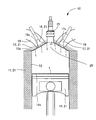
- FIG. 2 is an embodiment showing an engine.
- the engine 10 includes a cylinder block 11 in which a cylinder 12 is formed, and a cylinder head 13 attached so as to cover the upper surface of the cylinder block 11.
- a piston 14 is provided in the cylinder 12 of the cylinder block 11 so as to be slidable in the vertical direction.
- a spark plug 15 is attached to the cylinder head 13.
- an intake valve 16 and an exhaust valve 17 are attached.
- the intake valve 16 is configured to open and close an intake passage 18 formed in the cylinder head 13
- the exhaust valve 17 is configured to open and close an exhaust passage 19.
- the heat insulating member 1 is provided on the upper surface 14 s of the piston 14.
- the substrate 5 is a piston head.
- the heat insulating member 1 is provided on the valve heads 16 s and 17 s of the intake valve 16, the exhaust valve 17, and the bottom surface 13 s of the cylinder head 13. These surfaces are surfaces that form the engine combustion chamber 20, and by providing the heat insulating member 1 on these surfaces, the heat insulating performance can be improved.
- Fuel is supplied to the engine combustion chamber 20 surrounded by the cylinder 12, the cylinder head 13, and the piston 14 by opening the intake valve 16, and is burned by being ignited by the spark plug 15. By this combustion, the piston 14 is pushed down. The exhaust gas generated by the combustion is exhausted by opening the exhaust valve 17.
- the heat insulating member 1 can be fixed to the surface of the engine constituent member 21 constituting the engine combustion chamber 20 by mechanical fixing or chemical fixing.
- mechanical fixing include screwing and fitting.
- chemical fixation include brazing using a brazing material.
- chemical fixing it is not necessary to form screw holes in the substrate 5, and fixing is easy.
- the substrate 5 may be produced by casting together with a piston or the like.
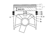
- FIG. 4A shows an embodiment in which the heat insulating member 1 is fixed to the piston 14 by screwing.
- the substrate 5 is a piston head.
- the substrate 5 (piston head) is formed in a disc shape having a convex portion 5a at the center.
- the screw hole 5b is formed in the convex-shaped part 5a. Note that the thickness of the substrate of this embodiment is the thickness of the portion shown in FIG.
- the heat insulating member 1 is placed on the upper surface 14 s of the piston 14, and the screw 8 is inserted into the screw hole 5 b of the convex portion 5 a from the back side of the upper portion of the piston. It can be fixed to the upper surface 14s.
- the heat insulating member 1 is fixed to the upper surface 14s of the piston 14, the heat insulating member 1 is disposed above the piston ring 14r. Therefore, the heat insulating member 1 does not contact the cylinder 12, and it is not necessary to consider friction. Therefore, restrictions on roundness and dimensional accuracy are small.
- FIG. 4B shows another embodiment in which the heat insulating member 1 is fixed to the piston 14 by screwing.
- the convex part 5a is formed in two steps, and the base part of the convex part 5a is formed thicker than the side into which the screw is inserted. That is, in this embodiment, the strength of the convex portion 5a is enhanced and the screw fastening portion is strong.
- the manufacturing method of the heat insulation member 1 is demonstrated.
- the substrate 5 is prepared.
- a slurry containing a ceramic raw material is prepared, formed into a disk shape or a plate shape, and fired to obtain a substrate 5.
- the surface dense layer 2 and the heat insulating porous layer 3 may be formed on the substrate 5 by first forming the heat insulating porous layer 3 and then forming the surface dense layer 2 or simultaneously.
- the heat insulating porous layer 3 can be formed on the substrate 5 by using a porous film forming method such as an EB-PVD method, a thermal spraying method, a CVD method, or a heat treatment after wet coating.
- a porous film forming method in which heat treatment is performed after particles are deposited by electrophoretic deposition, advection accumulation, or the like may be used.
- a porous thin plate may be separately prepared and attached to the substrate 5 with a bonding material.
- the heat insulating porous layer 3 may be formed by applying a paste obtained by adding filler particles (preferably hollow or porous) or a pore former to the binder and kneading them, and curing them, or by heat treatment. Since the heat insulating porous layer 3 is formed on the substrate 5, the firing temperature can be increased. Therefore, the material composition width of the heat insulating porous layer 3 is wide.
- the surface dense layer 2 is formed after the heat insulating porous layer 3 is formed, and after the sputtering method, PVD method, EB-PVD method, CVD method, AD method, thermal spraying, plasma spray method, cold spray method, plating, wet coating. It can be formed by heat treatment or the like. Alternatively, a dense thin plate may be separately prepared as the surface dense layer 2 and attached to the substrate 5 together with the heat insulating porous layer 3.
- the first bonding layer 4 a may be provided between the heat insulating porous layer 3 and the surface dense layer 2, and the second bonding layer 4 b may be provided between the substrate 5 and the heat insulating porous layer 3.
- the bonding layer 4 first bonding layer 4a, second bonding layer 4b
- an inorganic adhesive, a colloidal solution, a preceramic polymer, a brazing material, or the like is applied on the substrate 5.
- the second bonding layer 4b is formed by plating.
- the heat insulating porous layer 3 is formed thereon by the method as described above, the first bonding layer 4a is formed in the same manner as the second bonding layer 4b, and the surface dense layer 2 is formed by the method as described above. be able to.
- the heat insulating member 1 can be manufactured as follows. By forming a ceramic raw material to form a molded body to be the substrate 5, forming a layer to be the heat insulating porous layer 3 and the surface dense layer 2 on the unfired molded body, and integrally sintering them Moreover, the heat insulation member 1 can also be manufactured. Further, a molded body to be the substrate 5 is formed, a layer to be the heat insulating porous layer 3 is molded on the unfired molded body, and these are integrally sintered, and then a layer to be the surface dense layer 2 is molded. Further, the heat insulating member 1 can be manufactured by further sintering.
- Example 1 A piston base material having a shape as shown in FIG. 2 was prepared by aluminum die casting.
- a ceramic piston head (substrate 5) having a convex portion 5a and a screw hole 5b on the back side was prepared as follows so that the piston base and the screw could be fixed.
- a slurry comprising cordierite powder, a dispersant, a gelling agent, a reaction catalyst, and an organic dispersion medium was prepared.
- the slurry was poured into a mold at room temperature, left to stand, and then solidified at 40 ° C. and then released. Further, it was left at room temperature and then at 90 ° C. to obtain a molded body. This was fired at 1430 ° C. to obtain a dense cordierite piston head (substrate 5).
- heat insulating films (a surface dense layer 2 and a heat insulating porous layer 3) were formed on the surface of the piston head as follows. First, a slurry (for the heat-insulating porous layer 3) made of cordierite powder, latex particles as a pore-forming material, a dispersant, a binder, and water is prepared and applied to the surface (upper surface) of the piston head. , And then dried at 90 ° C. Next, a slurry composed of cordierite powder, a dispersant, a binder, and water (for the surface dense layer 2) is prepared, applied to the surface (upper surface) of the piston head, and dried at room temperature and then at 90 ° C. I let you. This was baked at 1380 ° C. to form a heat insulating film on the surface of the cordierite piston head, whereby the heat insulating member 1 was obtained.
- a slurry for the heat-insulating porous layer 3 made of cordierite powder, latex particles as a pore
- the piston 14 was obtained by joining the heat insulating member 1 to the piston base member with a screw and also arranging the piston ring 14r.
- Example 2 Similar to Example 1, a piston base material having a shape as shown in FIG. 2 was prepared.
- a ceramic piston head (substrate 5) having the same shape as in Example 1 was produced as follows. First, a slurry composed of zirconia powder, a dispersant, a gelling agent, a reaction catalyst, and an organic dispersion medium was prepared. The slurry was poured into a mold at room temperature, left to stand, and then solidified at 40 ° C. and then released. Further, it was left at room temperature and then at 90 ° C. to obtain a molded body. This was fired at 1400 ° C. to obtain a dense zirconia piston head (substrate 5).
- heat insulating films (a surface dense layer 2 and a heat insulating porous layer 3) were formed on the surface of the piston head as follows. First, a slurry composed of zirconia powder, melamine resin particles as a pore former, a dispersant, a binder, and water (for the heat insulating porous layer 3) is prepared, and this is applied to the surface (upper surface) of the piston head, Dry at room temperature and then at 90 ° C. Next, a slurry (for the surface dense layer 2) made of zirconia powder, a dispersant, a binder, and water was prepared, applied to the surface (upper surface) of the piston head, and dried at room temperature and then at 90 ° C. . This was baked at 1400 ° C. to form a heat insulating film on the surface of the zirconia piston head, whereby the heat insulating member 1 was obtained.
- the piston 14 was obtained by joining the heat insulating member 1 to the piston base member with a screw and also arranging the piston ring 14r.
- Comparative Example 1 A piston 14 using a piston head (only the substrate 5), which is the same as in Examples 1 and 2, but does not have a heat insulating film formed thereon, is referred to as Comparative Example 1.
- the engine combustion chamber structure of the present invention can be applied to engines such as automobiles.
Landscapes
- Engineering & Computer Science (AREA)
- Chemical & Material Sciences (AREA)
- General Engineering & Computer Science (AREA)
- Ceramic Engineering (AREA)
- Mechanical Engineering (AREA)
- Combustion & Propulsion (AREA)
- Materials Engineering (AREA)
- Structural Engineering (AREA)
- Organic Chemistry (AREA)
- Physics & Mathematics (AREA)
- Acoustics & Sound (AREA)
- Thermal Sciences (AREA)
- Cylinder Crankcases Of Internal Combustion Engines (AREA)
- Combustion Methods Of Internal-Combustion Engines (AREA)
Priority Applications (2)
| Application Number | Priority Date | Filing Date | Title |
|---|---|---|---|
| EP13755825.0A EP2821382A4 (fr) | 2012-02-27 | 2013-02-26 | Élément thermo-isolant et structure de chambre de combustion de moteur |
| US14/463,820 US20140352646A1 (en) | 2012-02-27 | 2014-08-20 | Heat-Insulating Member and Structure of Combustion Chamber for Engine |
Applications Claiming Priority (2)
| Application Number | Priority Date | Filing Date | Title |
|---|---|---|---|
| JP2012040438 | 2012-02-27 | ||
| JP2012-040438 | 2012-02-27 |
Related Child Applications (1)
| Application Number | Title | Priority Date | Filing Date |
|---|---|---|---|
| US14/463,820 Continuation US20140352646A1 (en) | 2012-02-27 | 2014-08-20 | Heat-Insulating Member and Structure of Combustion Chamber for Engine |
Publications (1)
| Publication Number | Publication Date |
|---|---|
| WO2013129430A1 true WO2013129430A1 (fr) | 2013-09-06 |
Family
ID=49082627
Family Applications (1)
| Application Number | Title | Priority Date | Filing Date |
|---|---|---|---|
| PCT/JP2013/055021 Ceased WO2013129430A1 (fr) | 2012-02-27 | 2013-02-26 | Élément thermo-isolant et structure de chambre de combustion de moteur |
Country Status (4)
| Country | Link |
|---|---|
| US (1) | US20140352646A1 (fr) |
| EP (1) | EP2821382A4 (fr) |
| JP (1) | JPWO2013129430A1 (fr) |
| WO (1) | WO2013129430A1 (fr) |
Cited By (6)
| Publication number | Priority date | Publication date | Assignee | Title |
|---|---|---|---|---|
| WO2015045286A1 (fr) * | 2013-09-30 | 2015-04-02 | マツダ株式会社 | Couche d'isolation thermique sur une surface d'un élément et son procédé de production |
| WO2015076317A1 (fr) * | 2013-11-19 | 2015-05-28 | 日本碍子株式会社 | Film calorifuge et structure à film calorifuge |
| WO2015080065A1 (fr) * | 2013-11-26 | 2015-06-04 | 日本碍子株式会社 | Matériau poreux et film thermo-isolant |
| JP2016102457A (ja) * | 2014-11-28 | 2016-06-02 | スズキ株式会社 | 遮熱膜の形成方法及び遮熱膜形成体、並びに内燃機関 |
| JP2019203450A (ja) * | 2018-05-23 | 2019-11-28 | 三菱重工エンジン&ターボチャージャ株式会社 | 遮熱膜部材 |
| WO2021019691A1 (fr) * | 2019-07-30 | 2021-02-04 | 三菱重工エンジン&ターボチャージャ株式会社 | Élément de film d'isolation thermique |
Families Citing this family (8)
| Publication number | Priority date | Publication date | Assignee | Title |
|---|---|---|---|---|
| US10302013B2 (en) * | 2015-09-30 | 2019-05-28 | Corning Incorporated | Composite thermal barrier for combustion chamber surfaces |
| DE102016107516A1 (de) * | 2016-04-22 | 2017-10-26 | Elringklinger Ag | Dichtung und Herstellungsverfahren für eine Dichtung |
| US10190533B2 (en) | 2016-08-08 | 2019-01-29 | GM Global Technology Operations LLC | Internal combustion engine and method for coating internal combustion engine components |
| CN109642696B (zh) * | 2016-08-26 | 2021-05-14 | 日本碍子株式会社 | 隔热部件 |
| JP6638618B2 (ja) * | 2016-10-19 | 2020-01-29 | トヨタ自動車株式会社 | エンジンの製造方法 |
| DE102017207236A1 (de) * | 2017-04-28 | 2018-10-31 | Mahle International Gmbh | Kolben für eine Brennkraftmaschine |
| US10578049B2 (en) | 2017-04-28 | 2020-03-03 | Mahle International Gmbh | Thermal barrier coating for engine combustion component |
| US11719184B1 (en) * | 2022-01-21 | 2023-08-08 | Tenneco Inc. | Piston with engineered crown coating and method of manufacturing |
Citations (8)
| Publication number | Priority date | Publication date | Assignee | Title |
|---|---|---|---|---|
| JPS61268850A (ja) * | 1985-05-23 | 1986-11-28 | Isuzu Motors Ltd | 燃焼室の断熱壁構造 |
| JPS63230947A (ja) | 1987-03-19 | 1988-09-27 | Kubota Ltd | エンジンのセラミツクスヘツド付金属ピストン |
| JPH03281936A (ja) * | 1990-03-29 | 1991-12-12 | Mazda Motor Corp | エンジンの燃焼室 |
| JPH07300374A (ja) * | 1994-04-28 | 1995-11-14 | Isuzu Motors Ltd | 遮熱部材の接合構造及びその接合方法 |
| JPH08284666A (ja) * | 1995-04-17 | 1996-10-29 | Yamaha Motor Co Ltd | 副燃焼室を備えるエンジン |
| JP2008533349A (ja) * | 2005-02-15 | 2008-08-21 | カーエス コルベンシュミット ゲゼルシャフト ミット ベシュレンクテル ハフツング | 内燃機関の燃焼室内の、排ガス腐食に対する保護層 |
| JP2010249008A (ja) | 2009-04-15 | 2010-11-04 | Toyota Motor Corp | エンジン燃焼室構造 |
| JP2011052630A (ja) | 2009-09-03 | 2011-03-17 | Toyota Motor Corp | 内燃機関 |
Family Cites Families (2)
| Publication number | Priority date | Publication date | Assignee | Title |
|---|---|---|---|---|
| JP3653388B2 (ja) * | 1998-03-13 | 2005-05-25 | 東芝セラミックス株式会社 | 焼成用道具材 |
| JP2002356387A (ja) * | 2001-03-30 | 2002-12-13 | Toshiba Ceramics Co Ltd | 耐プラズマ性部材 |
-
2013
- 2013-02-26 EP EP13755825.0A patent/EP2821382A4/fr not_active Withdrawn
- 2013-02-26 WO PCT/JP2013/055021 patent/WO2013129430A1/fr not_active Ceased
- 2013-02-26 JP JP2014502269A patent/JPWO2013129430A1/ja not_active Abandoned
-
2014
- 2014-08-20 US US14/463,820 patent/US20140352646A1/en not_active Abandoned
Patent Citations (8)
| Publication number | Priority date | Publication date | Assignee | Title |
|---|---|---|---|---|
| JPS61268850A (ja) * | 1985-05-23 | 1986-11-28 | Isuzu Motors Ltd | 燃焼室の断熱壁構造 |
| JPS63230947A (ja) | 1987-03-19 | 1988-09-27 | Kubota Ltd | エンジンのセラミツクスヘツド付金属ピストン |
| JPH03281936A (ja) * | 1990-03-29 | 1991-12-12 | Mazda Motor Corp | エンジンの燃焼室 |
| JPH07300374A (ja) * | 1994-04-28 | 1995-11-14 | Isuzu Motors Ltd | 遮熱部材の接合構造及びその接合方法 |
| JPH08284666A (ja) * | 1995-04-17 | 1996-10-29 | Yamaha Motor Co Ltd | 副燃焼室を備えるエンジン |
| JP2008533349A (ja) * | 2005-02-15 | 2008-08-21 | カーエス コルベンシュミット ゲゼルシャフト ミット ベシュレンクテル ハフツング | 内燃機関の燃焼室内の、排ガス腐食に対する保護層 |
| JP2010249008A (ja) | 2009-04-15 | 2010-11-04 | Toyota Motor Corp | エンジン燃焼室構造 |
| JP2011052630A (ja) | 2009-09-03 | 2011-03-17 | Toyota Motor Corp | 内燃機関 |
Non-Patent Citations (1)
| Title |
|---|
| See also references of EP2821382A4 |
Cited By (14)
| Publication number | Priority date | Publication date | Assignee | Title |
|---|---|---|---|---|
| WO2015045286A1 (fr) * | 2013-09-30 | 2015-04-02 | マツダ株式会社 | Couche d'isolation thermique sur une surface d'un élément et son procédé de production |
| JP2015068302A (ja) * | 2013-09-30 | 2015-04-13 | マツダ株式会社 | エンジン燃焼室に臨む部材表面の断熱層及びその製造方法 |
| CN105121824A (zh) * | 2013-09-30 | 2015-12-02 | 马自达汽车株式会社 | 部件表面的绝热层及其制造方法 |
| WO2015076317A1 (fr) * | 2013-11-19 | 2015-05-28 | 日本碍子株式会社 | Film calorifuge et structure à film calorifuge |
| JPWO2015076317A1 (ja) * | 2013-11-19 | 2017-03-16 | 日本碍子株式会社 | 断熱膜、および断熱膜構造 |
| CN105764872A (zh) * | 2013-11-26 | 2016-07-13 | 日本碍子株式会社 | 多孔材料及绝热膜 |
| JPWO2015080065A1 (ja) * | 2013-11-26 | 2017-03-16 | 日本碍子株式会社 | 多孔質材料及び断熱膜 |
| WO2015080065A1 (fr) * | 2013-11-26 | 2015-06-04 | 日本碍子株式会社 | Matériau poreux et film thermo-isolant |
| US10315961B2 (en) | 2013-11-26 | 2019-06-11 | Ngk Insulators, Ltd. | Porous material and heat insulating film |
| CN105764872B (zh) * | 2013-11-26 | 2020-08-14 | 日本碍子株式会社 | 多孔材料及绝热膜 |
| JP2016102457A (ja) * | 2014-11-28 | 2016-06-02 | スズキ株式会社 | 遮熱膜の形成方法及び遮熱膜形成体、並びに内燃機関 |
| JP2019203450A (ja) * | 2018-05-23 | 2019-11-28 | 三菱重工エンジン&ターボチャージャ株式会社 | 遮熱膜部材 |
| JP7082523B2 (ja) | 2018-05-23 | 2022-06-08 | 三菱重工エンジン&ターボチャージャ株式会社 | 遮熱膜部材 |
| WO2021019691A1 (fr) * | 2019-07-30 | 2021-02-04 | 三菱重工エンジン&ターボチャージャ株式会社 | Élément de film d'isolation thermique |
Also Published As
| Publication number | Publication date |
|---|---|
| EP2821382A1 (fr) | 2015-01-07 |
| US20140352646A1 (en) | 2014-12-04 |
| EP2821382A4 (fr) | 2015-11-04 |
| JPWO2013129430A1 (ja) | 2015-07-30 |
Similar Documents
| Publication | Publication Date | Title |
|---|---|---|
| WO2013129430A1 (fr) | Élément thermo-isolant et structure de chambre de combustion de moteur | |
| JP5977759B2 (ja) | エンジン燃焼室構造、および流路の内壁構造 | |
| JP6072787B2 (ja) | 断熱用多孔質板状フィラー、コーティング組成物、断熱膜、および断熱膜構造 | |
| WO2013125704A1 (fr) | Structure de chambre de combustion de moteur et structure de paroi intérieure de circuit fluidique | |
| JP6472384B2 (ja) | 断熱膜、および断熱膜構造 | |
| JP5315880B2 (ja) | 薄膜の形成方法及び内燃機関の製造方法 | |
| CN113272475B (zh) | 复合部件 | |
| JPS60235778A (ja) | セラミツク構造体及びその製造方法 | |
| JP2010185291A (ja) | 遮熱膜及びその形成方法 | |
| CN1973171A (zh) | 烧制炉及利用该烧制炉制造陶瓷部件的方法 | |
| JP6423360B2 (ja) | 断熱膜、および断熱膜構造 | |
| JP6373866B2 (ja) | 断熱膜、および断熱膜構造 | |
| WO2018147188A1 (fr) | Piston pour moteur à combustion interne et son procédé de fabrication | |
| JP5910416B2 (ja) | エンジン用ピストンの製造方法 | |
| JP2013177693A (ja) | 遮熱膜及びその形成方法 | |
| JP2014105619A (ja) | ピストン | |
| JP7129759B2 (ja) | 遮熱被膜層形成方法、および、遮熱被膜層を備えるエンジン部品 | |
| JP2012087347A (ja) | 多孔質材 | |
| JP2018096342A (ja) | 内燃機関 | |
| JPH03261685A (ja) | 断熱高強度セラミックとその製造方法 | |
| JPH02123255A (ja) | エンジンの構造 | |
| JPH03112872A (ja) | 断熱エンジンの構造とその製造方法 | |
| JPH07257984A (ja) | 断熱用セラミックスの製造方法 |
Legal Events
| Date | Code | Title | Description |
|---|---|---|---|
| 121 | Ep: the epo has been informed by wipo that ep was designated in this application |
Ref document number: 13755825 Country of ref document: EP Kind code of ref document: A1 |
|
| ENP | Entry into the national phase |
Ref document number: 2014502269 Country of ref document: JP Kind code of ref document: A |
|
| WWE | Wipo information: entry into national phase |
Ref document number: 2013755825 Country of ref document: EP |
|
| NENP | Non-entry into the national phase |
Ref country code: DE |