WO2013129496A1 - オイルセパレータ - Google Patents
オイルセパレータ Download PDFInfo
- Publication number
- WO2013129496A1 WO2013129496A1 PCT/JP2013/055188 JP2013055188W WO2013129496A1 WO 2013129496 A1 WO2013129496 A1 WO 2013129496A1 JP 2013055188 W JP2013055188 W JP 2013055188W WO 2013129496 A1 WO2013129496 A1 WO 2013129496A1
- Authority
- WO
- WIPO (PCT)
- Prior art keywords
- drain
- housing
- air
- oil separator
- oil
- Prior art date
- Legal status (The legal status is an assumption and is not a legal conclusion. Google has not performed a legal analysis and makes no representation as to the accuracy of the status listed.)
- Ceased
Links
Images


Classifications
-
- F—MECHANICAL ENGINEERING; LIGHTING; HEATING; WEAPONS; BLASTING
- F01—MACHINES OR ENGINES IN GENERAL; ENGINE PLANTS IN GENERAL; STEAM ENGINES
- F01M—LUBRICATING OF MACHINES OR ENGINES IN GENERAL; LUBRICATING INTERNAL COMBUSTION ENGINES; CRANKCASE VENTILATING
- F01M13/00—Crankcase ventilating or breathing
- F01M13/02—Crankcase ventilating or breathing by means of additional source of positive or negative pressure
-
- F—MECHANICAL ENGINEERING; LIGHTING; HEATING; WEAPONS; BLASTING
- F04—POSITIVE - DISPLACEMENT MACHINES FOR LIQUIDS; PUMPS FOR LIQUIDS OR ELASTIC FLUIDS
- F04B—POSITIVE-DISPLACEMENT MACHINES FOR LIQUIDS; PUMPS
- F04B39/00—Component parts, details, or accessories, of pumps or pumping systems specially adapted for elastic fluids, not otherwise provided for in, or of interest apart from, groups F04B25/00 - F04B37/00
- F04B39/04—Measures to avoid lubricant contaminating the pumped fluid
-
- B—PERFORMING OPERATIONS; TRANSPORTING
- B01—PHYSICAL OR CHEMICAL PROCESSES OR APPARATUS IN GENERAL
- B01D—SEPARATION
- B01D45/00—Separating dispersed particles from gases or vapours by gravity, inertia, or centrifugal forces
- B01D45/02—Separating dispersed particles from gases or vapours by gravity, inertia, or centrifugal forces by utilising gravity
-
- B—PERFORMING OPERATIONS; TRANSPORTING
- B01—PHYSICAL OR CHEMICAL PROCESSES OR APPARATUS IN GENERAL
- B01D—SEPARATION
- B01D45/00—Separating dispersed particles from gases or vapours by gravity, inertia, or centrifugal forces
- B01D45/04—Separating dispersed particles from gases or vapours by gravity, inertia, or centrifugal forces by utilising inertia
- B01D45/08—Separating dispersed particles from gases or vapours by gravity, inertia, or centrifugal forces by utilising inertia by impingement against baffle separators
-
- B—PERFORMING OPERATIONS; TRANSPORTING
- B01—PHYSICAL OR CHEMICAL PROCESSES OR APPARATUS IN GENERAL
- B01D—SEPARATION
- B01D46/00—Filters or filtering processes specially modified for separating dispersed particles from gases or vapours
- B01D46/0027—Filters or filtering processes specially modified for separating dispersed particles from gases or vapours with additional separating or treating functions
- B01D46/003—Filters or filtering processes specially modified for separating dispersed particles from gases or vapours with additional separating or treating functions including coalescing means for the separation of liquid
- B01D46/0031—Filters or filtering processes specially modified for separating dispersed particles from gases or vapours with additional separating or treating functions including coalescing means for the separation of liquid with collecting, draining means
-
- F—MECHANICAL ENGINEERING; LIGHTING; HEATING; WEAPONS; BLASTING
- F04—POSITIVE - DISPLACEMENT MACHINES FOR LIQUIDS; PUMPS FOR LIQUIDS OR ELASTIC FLUIDS
- F04B—POSITIVE-DISPLACEMENT MACHINES FOR LIQUIDS; PUMPS
- F04B39/00—Component parts, details, or accessories, of pumps or pumping systems specially adapted for elastic fluids, not otherwise provided for in, or of interest apart from, groups F04B25/00 - F04B37/00
- F04B39/16—Filtration; Moisture separation
-
- F—MECHANICAL ENGINEERING; LIGHTING; HEATING; WEAPONS; BLASTING
- F01—MACHINES OR ENGINES IN GENERAL; ENGINE PLANTS IN GENERAL; STEAM ENGINES
- F01M—LUBRICATING OF MACHINES OR ENGINES IN GENERAL; LUBRICATING INTERNAL COMBUSTION ENGINES; CRANKCASE VENTILATING
- F01M13/00—Crankcase ventilating or breathing
- F01M13/04—Crankcase ventilating or breathing having means for purifying air before leaving crankcase, e.g. removing oil
- F01M2013/045—Crankcase ventilating or breathing having means for purifying air before leaving crankcase, e.g. removing oil using compression or decompression of the gas
-
- F—MECHANICAL ENGINEERING; LIGHTING; HEATING; WEAPONS; BLASTING
- F01—MACHINES OR ENGINES IN GENERAL; ENGINE PLANTS IN GENERAL; STEAM ENGINES
- F01M—LUBRICATING OF MACHINES OR ENGINES IN GENERAL; LUBRICATING INTERNAL COMBUSTION ENGINES; CRANKCASE VENTILATING
- F01M13/00—Crankcase ventilating or breathing
- F01M13/04—Crankcase ventilating or breathing having means for purifying air before leaving crankcase, e.g. removing oil
- F01M2013/0472—Crankcase ventilating or breathing having means for purifying air before leaving crankcase, e.g. removing oil using heating means
Definitions
- This invention relates to the oil separator which isolate
- Vehicles such as trucks, buses, and construction machinery control systems such as brakes and suspensions using compressed air sent from a compressor directly connected to the engine.
- This compressed air contains moisture contained in the atmosphere and oil that lubricates the inside of the compressor.
- this compressed air containing moisture and oil enters each system, it causes rust generation and swelling of a rubber member (O-ring or the like), which causes malfunction.
- moisture content and oil content in compressed air is provided downstream of the compressor of an air system (for example, refer patent document 1).
- a filter In the air dryer, a filter, a desiccant such as silica gel and zeolite are provided.
- the air dryer performs a dehumidifying action for removing moisture from the compressed air and a regeneration action for regenerating the desiccant by removing the moisture adsorbed on the desiccant and releasing it to the outside.
- the oil released from the air dryer during regeneration of the desiccant contains oil as well as moisture, it is considered to provide an oil separator downstream of the air system compressor in consideration of environmental load.
- the collision plate type oil separator collects oil from the air and discharges clean air by performing gas-liquid separation by causing air containing moisture and oil to collide with the collision plate provided in the housing. (For example, patent document 2).
- the above oil separator stores drain, which is a liquid containing oil separated from air, at the bottom of the expansion chamber. Since this drain also contains moisture, when there is a lot of moisture separated from the air, the drain collection time (collection cycle) is shortened because the period until the drain accumulates to the limit of the storage amount is shortened. There is a fear. Therefore, there has been a demand for an oil separator in which the drain collection time (collection cycle) is extended.
- An object of the present invention is to provide an oil separator with a long drain recovery time (collection cycle).
- an oil including a housing having an air inlet, an expansion chamber provided in the housing, and a heating device that heats a lower portion of the expansion chamber.
- a separator Provides a separator.
- the oil separator introduces air containing oil into the casing through the introduction port, and separates and collects the oil from the introduced air.
- the expansion area of the expansion chamber is larger than the opening area of the inlet.
- a lid provided with an inlet for introducing purge air from an air dryer and an outlet for discharging clean air, a plurality of expansion chambers provided side by side in the vertical direction,
- An oil separator is provided that includes a housing attached to a lid and an attachment / detachment mechanism that allows the lid to be attached to and detached from the housing.
- the oil separator causes the purge air to flow into the casing and collide with a collision material, thereby separating oil from the purge air, collecting drain containing the oil, and discharging clean air.
- a through hole is formed between the expansion chambers to allow the purge air introduced from the introduction port to pass vertically downward.
- a casing provided with an inlet for introducing purge air from an air dryer and an outlet for discharging clean air, an expansion chamber provided in the casing,
- An oil separator comprising: a heating device that warms the casing. The oil separator causes the purge air to flow into the housing, separates the oil from the purge air, collects drain containing the oil, and discharges clean air.
- a housing having an air inlet and a drain outlet;
- An oil separator is provided that includes a collision material provided in the housing.
- the oil separator separates and collects oil from the introduced air by introducing air containing oil into the casing through the inlet and causing it to collide with a collision material.
- the oil separator further includes an expansion tank that is connected to the drain discharge port and stores the drain accumulated in the casing.
- FIG. 4 is a sectional view taken along line AA in FIG. 3.
- FIG. 4 is a sectional view taken along line BB in FIG. 3.
- the longitudinal cross-sectional view which shows the internal structure of the oil separator in the 2nd Embodiment of this invention.
- the block diagram which shows the structure of the oil separator of FIG.
- FIG. 14 is a cross-sectional view taken along line 14-14 of FIG.
- FIG. 15 is a sectional view taken along line 15-15 in FIG. 12;
- Sectional drawing which shows the internal structure of the elbow member of FIG. 16, and a dripping prevention member.
- the bottom view which shows the attachment / detachment mechanism of the oil separator of another example.
- Sectional drawing which shows the attachment / detachment mechanism of the oil separator of another example.
- Sectional drawing which shows the structure of the lower part of the oil separator of another example.
- the figure which shows the attachment state of the oil separator in the 4th Embodiment of this invention, and the connection state of an oil separator and an air dryer.
- the fragmentary broken view which shows the structure of the heating apparatus of the oil separator of FIG.
- FIG. 23 is a cross-sectional view showing the internal structure of the oil separator of FIG. FIG.
- FIG. 23 is a cross-sectional view showing the internal structure of the oil separator of FIG.
- the block diagram which shows the installation position of the oil separator in the air system of another example.
- the partially broken figure which shows the structure of the heating apparatus of the oil separator of another example.
- the block diagram which shows the installation position of the oil separator in the air system which concerns on the 5th Embodiment of this invention.
- FIG. 29 is a cross-sectional view of the expansion tank in FIG. 28.
- the block diagram which shows the installation position of the oil separator in the air system which concerns on another example.
- an air dryer 2 is provided downstream of the compressor 1 of the air system for removing oil and water from the compressed air and providing dried air.
- a desiccant is provided in the air dryer 2. The air dryer 2 performs a dehumidifying action for removing oil and water from the compressed air and a regenerating action for regenerating the desiccant by removing the oil and water adsorbed on the desiccant and releasing it to the outside.
- the air (purge air) released from the air dryer 2 during regeneration of the desiccant contains oil as well as moisture, so an oil separator 3 is provided downstream of the compressor 1 of the air system in consideration of environmental load.
- the oil separator 3 is provided in the exhaust system of the air dryer 2 and separates and recovers oil and moisture from the purge air discharged when the desiccant in the air dryer 2 is regenerated.
- the oil separator 3 is a collision plate type oil separator, and a plurality of collision plates in which air containing oil and moisture collides are provided in the casing.
- the collision plate type oil separator 3 collects oil from the air by colliding air containing oil and water with the collision plate to perform gas-liquid separation, and discharges clean air.
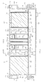
- the oil separator 3 includes a rectangular parallelepiped casing 4 extending in the horizontal direction.
- An introduction port 7 and a discharge port 8 are respectively formed on the front surface 5 and the back surface 6 of the housing 4 facing in the longitudinal direction. That is, in FIG. 2, air passes through the oil separator 3 from the left side to the right side.
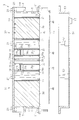
- a drain reservoir 50 for retaining drain separated from the air is attached to the bottom surface of the housing 4 with bolts 21 and nuts 22.
- the drain is a liquid containing oil and moisture.
- the drain reservoir 50 has a box shape that opens upward. Note that the bolt 21 and the nut 22 constitute an attaching / detaching mechanism.
- a drain communication portion 45 is fitted into the opening 16 on the bottom surface of the housing 4.
- the drain communication portion 45 is formed with a plurality of drain communication holes 46 that allow the inside of the housing 4 to communicate with the drain reservoir 50.
- the drain communication part 45 and the opening part 16 comprise the attachment / detachment mechanism.
- a drain discharge port 17 for discharging drain is formed in a portion near the back surface 6 in the bottom surface 51 of the drain reservoir 50.
- an opening 18 is formed on the upper surface of the housing 4.
- the opening 18 is closed by a rectangular lid 19.
- a sealing sheet 20 that covers the entire surface of the opening 18 is sandwiched between the opening 18 and the lid 19.
- the lid 19, the sealing sheet 20, and the housing 4 are fastened and fixed by a plurality of bolts 21 and nuts 22.
- the lid 19 restricts the movement of the member accommodated in the housing 4.
- a plate-like partition wall 30 is provided at the central portion in the longitudinal direction in the housing 4.
- the interior of the housing 4 is partitioned in a horizontal direction by a partition wall 30 into a primary expansion chamber 31 near the introduction port 14 and a secondary expansion chamber 32 near the discharge port 15.
- the cross-sectional areas of the primary expansion chamber 31 and the secondary expansion chamber 32 are each formed larger than the cross-sectional area of the introduction port 7.
- the cross-sectional area here corresponds to the area in a cross section perpendicular to the longitudinal direction of the housing 4.
- a through-hole (orifice hole) 30a is formed at one location in the upper part of the partition wall 30. Therefore, the partition wall 30 functions as an orifice that controls the flow of air from the primary expansion chamber 31 to the secondary expansion chamber 32 by the orifice hole 30a.
- a communication hole 33 is formed at one location in the lower part of the partition wall 30 near the opening 16. The communication hole 33 allows the drain separated and collected from the air to pass between the expansion chambers 31 and 32.
- a pair of opposing collision plates 34 and 35 are provided on both sides of the partition wall 30 in the housing 4.
- the first collision plate 34 on the upstream side includes a first standing plate 34 a extending from the opening 16 of the housing 4 to the lid 19, and a first standing plate toward the discharge port 8 in the longitudinal direction of the housing 4. And a first baffle plate 34b extending vertically from 34a.
- the first standing plate 34a has a rectangular first through hole 34c extending in the width direction of the collision plates 34 and 35 below the connecting portion to the first baffle plate 34b.
- the second collision plate 35 on the downstream side includes a second standing plate 35 a extending from the opening 16 of the housing 4 to the lid 19, and a second standing plate toward the introduction port 7 in the longitudinal direction of the housing 4. And a second baffle plate 35b extending vertically from the installation plate 35a.
- the second standing plate 35a has a rectangular second through hole 35c extending in the width direction of the collision plates 34 and 35 above the connection portion to the second baffle plate 35b.
- the first baffle plate 34b and the second baffle plate 35b protrude so as to obstruct the air flow path, and an extremely narrow portion that is a narrow gap between the surfaces by bringing the large surfaces close to each other 36 is formed.
- the first baffle plate 34b is located closer to the lid 19 than the second baffle plate 35b.
- the extremely narrow portion 36 increases the passage speed of air, and further increases the chance of collision of the oil / water particles with the plate by meandering the flow path, so that the oil / water is further separated from the air.
- the baffle plates 34 b and 35 b are present, the oil and water dropped while passing between the first collision plate 34 and the second collision plate 35 is between the first collision plate 34 and the second collision plate 35.
- One communication hole 33 is formed in the lower part of the first collision plate 34 and the second collision plate 35 near the opening 16. The communication hole 33 allows the drain separated and collected from the air to pass through.
- a pair of collision plates 34 and 35 are provided in the space inside the primary expansion chamber 31.
- a urethane foam 38 such as a sponge is installed between the introduction port 7 and the pair of collision plates 34 and 35.
- a punching metal plate 37 having a plurality of holes is attached to a surface of the urethane foam 38 facing the collision plate 34.
- the urethane foam 38 captures oil moisture contained in the air.
- a pair of collision plates 34 and 35 are also provided in the space inside the secondary expansion chamber 32.
- a crashed aluminum 39 is installed between the pair of collision plates 34 and 35 and the discharge port 8.
- a punching metal plate 37 having a plurality of holes is attached to the surfaces of the crashed aluminum 39 facing the collision plates 34 and 35, respectively. That is, the crashed aluminum 39 is sandwiched between a pair of punching metal plates 37.
- the crashed aluminum 39 captures oil moisture contained in the air.
- Each of the expansion chambers 31 and 32 is provided with a rib 40 for increasing the strength of the housing 4.
- the drain reservoir 50 is provided with four ribs 52 for increasing the strength.
- Two drain communication holes 46 of the drain communication portion 45 are formed in each of the expansion chambers 31 and 32, and correspond to the urethane foam 38, the collision plates 34 and 35, and the crashed aluminum 39, respectively.
- the drain communication portion 45 and the drain reservoir portion 50 can be attached to and detached from the housing 4. That is, the drain communication portion 45 is fitted into the opening 16 of the housing 4, and the drain reservoir 50 is attached to the bottom surface of the housing 4. For this reason, the drain accumulated in the drain communicating portion 45 and the drain reservoir 50 can be easily removed by removing the drain communicating portion 45 and the drain reservoir 50 from the housing 4.
- the drain reservoir 50 attached to the lower part of the housing 4 is hollow and can accumulate drain until the drain liquid level reaches the lower surface of the drain communication part 45.
- a columnar accommodating portion 23 for accommodating a heater 41 as a heating means (heating device) is formed near the bottom surface 51 of the rib 52 of the drain reservoir 50.
- An insertion port 24 for inserting the heater 41 is formed on the outer surface of the drain reservoir 50, and the insertion port 24 penetrates the housing unit 23.
- the heater 41 has a columnar shape and is inserted into the accommodating portion 23 from the outer surface of the drain reservoir 50.
- the heater 41 is connected to a power source.
- a mounting hole 25 for attaching the thermostat 42 is formed above the insertion port 24 on the outer surface of the drain reservoir 50.
- the thermostat 42 is attached to the attachment hole 25 and connected to the power source and the heater 41.
- the thermostat 42 detects the temperature of the drain reservoir 50 and controls the heating of the heater 41 based on the detected temperature.
- the air introduced into the primary expansion chamber 31 from the introduction port 7 passes through the urethane foam 38 while capturing oil and moisture by the urethane foam 38, and the first through hole 34 c of the first collision plate 34 of the primary expansion chamber 31. Pass through. At this time, the oil and water colliding with the first standing plate 34a is separated from the air.
- the air that has passed through the first through hole 34c is directed to the narrow portion 36 formed by the first baffle plate 34b and the second baffle plate 35b, and passes through the narrow portion 36. At this time, the oil and water colliding with the second upright plate 35a and the second baffle plate 35b are separated from the air.
- the drain containing moisture and oil captured by the urethane foam 38 moves along the urethane foam 38.
- the drain falls from the drain communication hole 46 located below the urethane foam 38 to the drain reservoir 50 and is accumulated in the drain reservoir 50.
- the drain that collides with and is separated from the first collision plate 34 of the primary expansion chamber 31 passes through the communication hole 33 of the first collision plate 34 and drains from the drain communication hole 46 located below the collision plates 34 and 35. It falls into the reservoir 50 and accumulates in the drain reservoir 50.
- the air that has passed through the extremely narrow portion 36 passes through the second through hole 35c of the second standing plate 35a toward the orifice hole 30a of the partition wall 30, and passes through the orifice hole 30a. At this time, the oil and water colliding with the partition wall 30 are separated from the air.
- the drain that collides with and is separated from the second collision plate 35 of the primary expansion chamber 31 passes through the communication hole 33 of the second collision plate 35 and drains from the drain communication hole 46 located below the collision plates 34 and 35. It falls into the reservoir 50 and accumulates in the drain reservoir 50.
- the air that has passed through the orifice hole 30 a of the partition wall 30 passes through the first through hole 34 c of the first standing plate 34 a of the secondary expansion chamber 32. At this time, the oil and water colliding with the first standing plate 34a is separated from the air.
- the air that has passed through the first through hole 34c is directed to the narrow portion 36 formed by the first baffle plate 34b and the second baffle plate 35b, and passes through the narrow portion 36. At this time, the oil and water colliding with the second upright plate 35a and the second baffle plate 35b are separated from the air.
- the drain that collides and is separated from the partition wall 30 passes through the communication hole 33 of the partition wall 30 and the communication hole 33 of the first collision plate 34 of the secondary expansion chamber 32, and is located below the collision plates 34 and 35.
- the fluid falls from the communication hole 46 to the drain reservoir 50 and accumulates in the drain reservoir 50.
- the air that has passed through the extremely narrow portion 36 passes through the second through hole 35 c of the second standing plate 35 a, travels toward the crashed aluminum 39, and passes through the crashed aluminum 39. At this time, the air introduced into the crushed aluminum 39 passes through the crushed aluminum 39 while further capturing oil and moisture by the crushed aluminum 39, and clean air that does not contain oil is discharged from the discharge port 15 to the outside.
- the drain that collides with and is separated from the first collision plate 34 of the secondary expansion chamber 32 passes through the communication hole 33 of the first collision plate 34 and passes through the drain communication hole 46 located below the collision plates 34 and 35. It falls into the drain reservoir 50 and accumulates in the drain reservoir 50.
- the drain that collides with and is separated from the second collision plate 35 of the secondary expansion chamber 32 passes through the communication hole 33 of the second collision plate 35 and passes through the drain communication hole 46 located below the collision plates 34 and 35. It falls into the drain reservoir 50 and accumulates in the drain reservoir 50.
- the drain captured by the crashed aluminum 39 moves along the crashed aluminum 39, falls from the drain communication hole 46 located below the crashed aluminum 39 to the drain reservoir 50, and enters the drain reservoir 50. Accumulate.
- the drain accumulated in the drain reservoir 50 is heated by the heater 41. Thereby, the water in the drain is evaporated. Drain containing oil at a high concentration is discharged from the drain discharge port 17.
- the inside of the drain reservoir 50 can be cleaned by removing the drain reservoir 50 from the housing 4.
- the heater 41 Since the heater 41 is provided below the expansion chambers 31 and 32, the drain containing oil and water that collides with the collision plates 34 and 35 and accumulates at the bottom of the expansion chambers 31 and 32 is heated by the heater 41. . Therefore, the water in the drain can be evaporated. Therefore, by reducing the water content from the accumulated drain, the concentration of oil can be increased, the amount of drain stored can be reduced, and the drain recovery time (recovery cycle) can be prolonged. Furthermore, by heating the housing 4 with the heater 41, it is possible to prevent the drain from being discharged from the drain discharge port 17 due to the freezing of the drain even in a cold region.
- the heater 41 is accommodated in the accommodating portion 23 provided in the lower part of the housing 4. Since the heater 41 heats the housing 4, it is possible to prevent the heater 41 from being deteriorated by the drain containing oil and moisture.
- the drain reservoir 50 can be detached from the housing 4 by the attaching / detaching mechanism using the bolt 21 and the nut 22, the drain reservoir 50 can be cleaned while being detached from the housing 4.
- the oil can be easily removed when the oil adheres to the inner wall of the drain reservoir. Further, if the drain reservoir is made disposable, the drain can be easily recovered.
- a first drain receiver 55 for collecting the collected drain is provided at the lower part of the housing 4.
- the bottom portion of the first drain receiver 55 is inclined so that the depth in the vertical direction becomes deeper toward the secondary expansion chamber 32 along the longitudinal direction of the housing 4.
- a box-shaped second drain receiver 57 is provided on the outer surface of the first drain receiver 55 near the secondary expansion chamber 32.
- the first drain receiver 55 communicates with the second drain receiver 57 near their bottom surfaces. For this reason, only the moisture contained in the drain moves from the first drain receiver 55 to the second drain receiver 57 through the communicating portion.
- a drain filter 56 is installed at the communication portion to prevent oil from entering. Near the bottom surface of the second drain receiver 57, a heater 41 for heating the drain is installed.
- a water vapor filter 58 that passes only water vapor is installed so that only water is discharged to the outside.
- the oil is separated from the air through the primary expansion chamber 31, the collision plates 34 and 35, and the secondary expansion chamber 32, so that cleaning air that does not contain the oil is discharged to the outside.
- the drain separated and collected from the air by the primary expansion chamber 31, the collision plates 34 and 35, and the secondary expansion chamber 32 is stored in the first drain receiver 55.
- the drain accumulated in the first drain receiver 55 contains oil at a relatively high concentration. When water and oil are separated in the drain, the oil moves upward and the water moves downward.
- the drain accumulated in the first drain receiver 55 passes through the drain filter 56 and moves to the second drain receiver 57.
- the drain stored in the second drain receiver 57 contains oil at a relatively low concentration because the moisture moves downward.
- the drain stored in the second drain receiver 57 is heated by the heater 41, and the water in the drain is evaporated. Water vapor generated by the heating of the heater 41 is discharged to the outside through the water vapor filter 58.
- the air dryer 2 includes a bottomed cylindrical case 121 whose top is closed vertically, and a support member 122 that closes the opening of the case 121 and supports the case 121. .
- a purge air discharge port 123 that discharges purge air when the drying agent is regenerated is formed below the support member 122.
- a purge air discharge cover 124 to which a connection hose 125 is connected is attached to the purge air discharge port 123.
- the connection hose 125 is connected to the oil separator 103.
- the support member 122 of the air dryer 2 is provided with an inlet (not shown) for introducing the compressed air compressed by the compressor 1 and an outlet (not shown) for discharging the dried compressed air. ing.
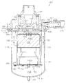
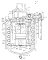
- the oil separator 103 includes a case 131 as a bottomed cylindrical casing extending in the vertical direction and a lid 132 that closes the opening of the case 131.
- the bottom 131a of the case 131 is provided with a drain discharge port 133 for discharging the accumulated drain.
- a drain hose 134 used for draining is connected to the drain outlet 133.
- an inlet 135 for introducing purge air from the air dryer 2 through the connection hose 125 and an outlet 140 for discharging clean air from which oil has been separated are formed separately.
- the introduction port 135 and the connection hose 125 are connected by a connecting member 127.
- a mounting member 137 is integrally provided on the lid 132 of the oil separator 103 with respect to the lid 132.
- the attachment member 137 is fixed to the chassis 138 with bolts 139.
- the distal end of the drain hose 134 is detachably attached to a support member 190 fixed to the vehicle chassis 138 and the like. That is, the fixing member 191 is fixed to the support member 190.
- a one-touch coupler 192 to which the tip end of the drain hose 134 can be attached with one touch is fixed to the lower end of the fixing member 191.
- the drain hose 134 is fixed to the fixing member 191 by inserting the distal end portion of the drain hose 134 into the one-touch coupler 192, and can be removed from the fixing member 191 by operating the one-touch coupler 192.
- the distal end portion of the drain hose 134 is attached to the fixing member 191 vertically upward.
- An elbow member 160 that bends vertically upward from the horizontal direction is screwed to the discharge port 140 of the oil separator 103.
- a dripping prevention member 170 is attached to the tip of the elbow member 160, and a cover 180 that prevents intrusion of dust and the like is attached.
- the inlet 132 and the outlet 140 are opened in the same direction (right side in the figure) in the lid 132.
- the introduction port 135 and the discharge port 140 are respectively provided on the surface in the horizontal direction.
- a connection hose 125 is connected to the introduction port 135 via a connecting member 127.
- An elbow member 160 is connected to the discharge port 140. That is, the connecting member 127 and the elbow member 160 are provided side by side.
- the lid 132 has a bottomed cylindrical shape with the top vertically closed.
- Two baffle plates 146 are erected on the inner wall of the lid 132 in the vicinity of the inlet 135 so as to be orthogonal to the traveling direction of the purge air introduced from the inlet 135.
- the internal space of the lid 132 functions as a first expansion chamber 145 that expands the purge air introduced from the introduction port 135.
- the cross-sectional area of the purge air path formed in the first expansion chamber 145 is larger than the cross-sectional area of the inlet 135.
- the cross-sectional area here corresponds to the area in a cross section perpendicular to the traveling direction of the purge air.
- the lid 132 is formed with a communication portion 132 a that communicates from the inside of the case 131 to the discharge port 140.
- a disc-shaped cover 147 that closes the case 131 and closes the opening of the lid 132 is provided between the case 131 and the lid 132.
- the cover 147 is fastened to the lid 132 together with the case 131 by bolts 136. That is, the bolt 136 is fastened to the screw hole 132 c formed in the flange portion 132 b provided in the lid 132.
- the bolt 136 and the screw hole 132c function as an attaching / detaching mechanism. Further, the screw portion of the bolt 136 is passed through a through hole formed in the flange portion 131 b provided in the case 131.
- the cover 147 is formed with a through hole through which the threaded portion of the bolt 136 passes.
- the screw part of the bolt 136 is passed through the through hole of the flange part 131b of the case 131 and the through hole of the flange part 147a of the cover 147, and the bolt 136 is screwed into the screw hole 132c of the flange part 132b of the lid 132.
- the case 131 can be removed from the lid 132 by removing the bolt 136 from the screw hole 132c.
- the cover 147 is formed with a communication hole 147 c that communicates from the inside of the case 131 to the discharge port 140.
- a space formed by the lid 132 and the cover 147 functions as the first expansion chamber 145.
- a cylindrical housing member 148 with a bottom closed vertically is fixed to the cover 147 with bolts 136.
- the accommodating member 148 accommodates the urethane foam 150 such as a sponge. Note that the urethane foam 150 functions as a collision material.
- a flange portion 148 a and a flange portion 148 b are formed on the upper edge portion and the lower edge portion of the housing member 148.
- a bolt 136 is passed through a flange portion 148 a formed at the upper edge of the housing member 148, and the housing member 148 is fastened to the cover 147.
- a space formed by the cover 147 and the upper surface of the housing member 148 functions as the second expansion chamber 151.
- the cover 147 is formed with a plurality of through holes 147 b that allow the first expansion chamber 145 to communicate with the second expansion chamber 151.
- a plurality of through holes 149 a are formed in the central portion of the upper bottom portion 149 of the housing member 148.
- the through hole 147b of the cover 147 and the through hole 149a of the upper bottom portion 149 of the housing member 148 are formed at positions that do not face each other.
- a plurality of through-holes 148c are formed on the lower end portion side of the side surface of the housing member 148 at intervals in the radial direction.
- a disk-shaped support lid 152 is fixed to the flange portion 148 b formed at the lower edge of the housing member 148 with a screw 153.
- the support lid 152 supports the urethane foam 150 accommodated in the accommodation member 148.
- the inner diameter of the support lid 152 is substantially the same as the inner diameter of the case 131.
- a space formed by the upper bottom portion 149 of the housing member 148 and the support lid 152 functions as the third expansion chamber 159.
- the support lid 152 is formed with a plurality of through holes 152a through which oil and water removed by the urethane foam 150 are dropped. Therefore, the lower part in the case 131 functions as the drain reservoir 154.
- the drain reservoir 154 is provided with a heater 155 as a heating device for heating the accumulated drain and evaporating water in the drain.
- the heater 155 is inserted into the case 131 through an insertion hole 156 formed in the side surface of the case 131.
- the heater 155 directly heats the drain accumulated in the drain reservoir 154. Heating of the heater 155 is controlled by a thermostat (not shown).
- the elbow member 160 includes a horizontal portion 161 extending in the horizontal direction and a vertical portion 162 extending in the vertical direction continuously to the horizontal portion 161.
- a male screw portion 163 that is screwed into the female screw portion 140 a of the discharge port 140 is formed at the base end portion of the elbow member 160.
- the male screw part 163 of the elbow member 160 is formed such that when the elbow member 160 is screwed to the female screw part 140a of the discharge port 140, fastening is stopped at a position where the tip of the elbow member 160 faces upward.
- a female screw part 164 to which the dripping prevention member 170 is screwed is formed at the tip of the elbow member 160.
- a through-hole 171 that connects the base end and the distal end is formed inside the liquid dripping prevention member 170, and four partition plates 172 that prevent large foreign substances from entering the flow path and blocking the flow path are provided. ing.
- the partition plates 172 are formed to extend in the axial direction at equal intervals in the circumferential direction.
- a cylindrical portion 173 is formed at the center of the through-hole 171 and at the intersection of the partition plates 172.
- a male screw portion 174 that is screwed to the female screw portion 164 of the elbow member 160 is formed at the base end portion of the liquid dripping prevention member 170.
- a liquid dripping part 176 that receives liquid dripping from the opening 175 is formed over the entire circumference.
- a return hole 177 serving as a return portion for returning the liquid received by the liquid drooping portion 176 to the through hole 171 is formed at the bottom of the liquid drooping portion 176.
- the return hole 177 penetrates from the liquid dripping part 176 to the through hole 171. Therefore, the liquid dripping on the liquid dripping part 176 returns to the elbow member 160 through the return hole 177.
- a stepped portion 182 is formed in the insertion portion 181. The stepped portion 182 sets the insertion position of the cover 180 with respect to the dripping prevention member 170.
- the cover 180 covers the opening 175 of the dripping prevention member 170.
- the outer diameter of cover 180 is smaller than the inner diameter of liquid drooping portion 176. Therefore, the clean air that has passed through the dripping prevention member 170 passes between the opening 175 of the dripping prevention member 170 and the inner surface of the cover 180 and is discharged to the outside.
- purge air discharged from the air dryer 2 is introduced into the oil separator 103.
- the purge air is air containing oily moisture.
- the purge air introduced from the introduction port 135 collides with the baffle plate 146, is introduced into the oil separator 103 along the baffle plate 146, and expands in the first expansion chamber 145.
- the air expanded in the first expansion chamber 145 enters the second expansion chamber 151 through a through hole 147 b formed in the cover 147.
- the air expanded in the second expansion chamber 151 enters the third expansion chamber 159 through the through hole 149a in the upper bottom portion 149 of the housing member 148.
- the drain containing water and oil captured by the urethane foam 150 moves along the urethane foam 150.
- the drain reaches the upper surface of the support lid 152, falls from the through hole 152 a of the support lid 152 to the drain reservoir 154, and accumulates in the drain reservoir 154.
- the drain accumulated in the drain reservoir 154 enters the drain hose 134 from the drain discharge port 133.
- the drain accumulated in the drain reservoir 154 is heated by the heater 155. Thereby, the water in the drain is evaporated.
- the drain in the drain hose 134 is positioned at the same height as the drain in the drain reservoir 154. Therefore, by visually checking the drain in the drain hose 134, the amount of drain in the drain reservoir 154 can be confirmed.
- air that has entered the third expansion chamber 159 from the through hole 149 a of the upper bottom portion 149 of the housing member 148 and has been separated from oil and moisture is passed through the through hole 148 c on the side surface of the housing member 148. Enters the case 131.
- the air that has entered the case 131 passes through the communication hole 147c of the cover 147 and the communication part 132a of the lid 132, flows into the elbow member 160 from the discharge port 140, and is discharged to the atmosphere. Therefore, the air that has entered the case 131 is discharged from the discharge port 140 with almost no contact with the drain of the drain reservoir 154.
- the air discharged from the discharge port 140 is clean air that does not contain oil.
- the one-touch coupler 192 When discharging the drain accumulated in the drain reservoir 154, the one-touch coupler 192 is operated to remove the tip of the drain hose 134 from the one-touch coupler 192, and the tip of the drain hose 134 is drained from the drain reservoir 154. Lower than the surface of the water. As a result, the drain can be discharged from the drain reservoir 154.
- the case 131 and the cover 147 are removed from the lid 132 by removing the bolt 136 from the screw hole 132c.
- the removed case 131 and cover 147 can be cleaned.
- the screw 153 fixing the support lid 152 to the housing member 148 is removed, the urethane foam 150 is taken out from the housing member 148, and the urethane foam 150 is replaced.
- the case 131 and the cover 147 are attached to the lid 132 by fixing the support lid 152 to the housing member 148 with screws 153 and fastening the bolt 136 to the screw hole 132c of the lid 132.
- the inlet 135 and the outlet 140 are provided in the lid 132, and purge air introduced into the case 131 from the inlet 135 passes vertically downward through the plurality of expansion chambers 145, 151, 159, and the outlet 140. Clean air is discharged from
- the case 131 can be removed from or attached to the lid 132 by a bolt 136 and a screw hole 132c as an attaching / detaching mechanism. For this reason, the case can be easily separated by removing the case 131 from the lid 132.
- the inlet 135 and the outlet 140 are provided on the horizontal surface of the lid 132, respectively. For this reason, since the inlet 131 and the outlet 140 are not provided in the case 131, there is no pipe connected to the case 131 when the case 131 is removed from the lid 132, and the case 131 can be easily removed. In addition, since the pipe is not connected to the upper surface or the bottom surface in the vertical direction of the lid 132, the length in the vertical direction can be suppressed.
- the heater 155 is inserted from the insertion hole 156 provided in the lower part of the case 131, and the heater 155 directly heats the drain. For this reason, the water
- the oil separator 203 is provided with a heating device 280.
- the heating device 280 warms the oil separator 203 by allowing high-temperature compressed air supplied from the compressor 1 to pass through the outer periphery of the oil separator 203. That is, the compressed air of the compressor 1 is supplied to the air dryer 2 via the outer periphery of the oil separator 203.
- the temperature of the compressed air supplied from the compressor 1 is as high as 160 ° C.
- the air dryer 2 includes a bottomed cylindrical case 221 whose top is closed and a support member 222 that closes the opening of the case 221 and supports the case 221. .
- a purge air discharge port 223 that discharges purge air when the drying agent is regenerated is formed below the support member 222.
- a purge air discharge cover 224 to which a connection hose 225 is connected is attached to the purge air discharge port 223.
- the connection hose 225 is connected to the oil separator 203.
- the support member 222 of the air dryer 2 is provided with an inlet 228 for introducing compressed air compressed by the compressor 1 and an outlet 229 for discharging the dried compressed air.
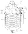
- the oil separator 203 includes a case 231 as a bottomed cylindrical casing extending in the vertical direction, and a lid 232 that closes the opening of the case 231.
- a drain discharge port 233 for discharging the accumulated drain is provided at the bottom 231a of the case 231.
- a drain hose 234 is connected to the drain outlet 233 for use when taking out the drain.
- the lid 232 is separately formed with an inlet 235 for introducing purge air from the air dryer 2 via a connection hose 225 and an outlet 240 for discharging clean air from which oil has been separated.
- the introduction port 235 and the connection hose 225 are connected by a connecting member 227.
- An attachment member 237 is integrally provided on the lid 232 of the oil separator 203 with respect to the lid 232.
- the attachment member 237 is fixed to the chassis 238 by bolts.
- the distal end of the drain hose 234 is detachably attached to a support member 260 fixed to a vehicle chassis 238 or the like. That is, the fixing member 261 is fixed to the support member 260.
- a one-touch coupler 262 to which the tip end of the drain hose 234 can be attached with one touch is fixed to the lower end portion of the fixing member 261.
- the drain hose 234 is fixed to the fixing member 261 by inserting the distal end portion of the drain hose 234 into the one-touch coupler 262, and can be detached from the fixing member 261 by operating the one-touch coupler 262.
- the distal end portion of the drain hose 234 is attached to the fixing member 261 upward in the vertical direction.
- the leading end of the drain hose 234 is located above the lid 232 of the oil separator 203. For this reason, it is possible to prevent the drain from leaking from the tip of the drain hose 234.
- a cylindrical jacket 281 constituting the heating device 280 is attached to the outer periphery of the case 231 of the oil separator 203.
- the jacket 281 is detachable from the case 231.
- An inlet connecting pipe 282 for connecting the compressor 1 and introducing compressed air from the compressor 1 is connected to the upper side surface of the jacket 281.
- a discharge connection pipe 283 for connecting the air dryer 2 and discharging compressed air to the air dryer 2 is connected to the lower side of the jacket 281.
- the discharge connection pipe 283 is connected to the inlet 228 of the air dryer 2.
- the heating device 280 warms the case 231 by drawing the compressed air of the compressor 1 into the jacket 281.
- the heating device 280 cools the compressed air supplied from the compressor 1 and discharges it to the air dryer 2 by moving the amount of heat of the compressed air supplied from the compressor 1 to the case 231 via the jacket 281.
- the temperature of the compressed air cooled through the jacket 281 is about 60 ° C.
- the jacket 281 is provided with a guide tube 284 that extends spirally along the outer periphery of the case 231.
- the guide pipe 284 connects the introduction connection pipe 282 to the discharge connection pipe 283.
- the introduction port 235 and the discharge port 240 provided in the lid 232 are open in the same direction (right side in the figure).
- a connection hose 225 is connected to the introduction port 235 via a connecting member 227.
- a discharge hose 242 is connected to the discharge port 240 via a connection member 241 that bends downward from the horizontal direction. That is, the connecting member 227 and the connecting member 241 are provided side by side.
- the tip opening of the discharge hose 242 is formed such that the length in the vertical direction of the portion near the case 231 is shorter than the length in the opposite portion, and the end surface of the tip opening is formed obliquely with respect to the horizontal direction. . This enhances waterproofness while facilitating the discharge of clean air from the discharge hose 242.
- the lid 232 has a bottomed cylindrical shape with the top vertically closed.
- Two baffle plates 246 are erected on the inner wall of the lid 232 in the vicinity of the inlet 235 so as to be orthogonal to the traveling direction of the purge air introduced from the inlet 235.
- the internal space of the lid 232 functions as a first expansion chamber 245 that expands purge air introduced from the introduction port 235.
- the lid 232 is formed with a communication portion 232 a that communicates from the inside of the case 231 to the discharge port 240.
- a disc-shaped cover 247 that closes the case 231 and closes the opening of the lid 232 is provided between the case 231 and the lid 232.
- the cover 247 is fastened to the lid 232 together with the case 231 by bolts 236. That is, the bolt 236 is fastened to the screw hole formed in the flange portion 232 b provided in the lid 232. Further, the screw portion of the bolt 236 is passed through the through-hole formed in the flange portion 231b provided in the case 231.
- the cover 247 is formed with a through hole through which the screw portion of the bolt 236 passes.
- the screw portion of the bolt 236 is passed through the through hole of the flange portion 231b of the case 231 and the through hole of the flange portion 247a of the cover 247, and the bolt 236 is screwed into the screw hole of the flange portion 232b of the lid 232.
- the cover 247 has a communication hole 247 c that communicates from the inside of the case 231 to the discharge port 240.
- a space formed by the lid 232 and the cover 247 functions as the first expansion chamber 245.
- a cylindrical housing member 248 with a bottom closed vertically is fixed to the cover 247 with bolts 239.
- the accommodating member 248 accommodates a urethane foam 250 such as a sponge.
- the urethane foam 250 functions as a collision material.
- a flange portion 248 a and a flange portion 248 b are formed on the upper edge portion and the lower edge portion of the housing member 248.
- a bolt 239 is passed through a flange portion 248 a formed at the upper edge of the housing member 248, and the housing member 248 is fastened to the cover 247.
- a space formed by the cover 247 and the upper surface of the housing member 248 functions as the second expansion chamber 251.
- the cover 247 is formed with a plurality of through holes 247 b that allow the first expansion chamber 245 to communicate with the second expansion chamber 251.
- a plurality of through holes 249 a are formed in the central portion of the upper bottom portion 249 of the housing member 248.
- the through hole 247b of the cover 247 and the through hole 249a of the upper bottom portion 249 of the housing member 248 are formed at positions that do not face each other.
- a plurality of through holes 248c are formed at intervals in the radial direction on the lower end portion side of the side surface of the housing member 248.
- a disk-shaped support lid 252 is fixed to the flange portion 248 b formed at the lower edge of the housing member 248 with a screw 253.
- the support lid 252 supports the urethane foam 250 accommodated in the accommodation member 248.
- the inner diameter of the support lid 252 is substantially the same as the inner diameter of the case 231.
- a space formed by the upper bottom portion 249 of the housing member 248 and the support lid 252 functions as the third expansion chamber 259.
- the support lid 252 is formed with a plurality of through holes 252a through which oil and moisture removed by the urethane foam 250 are dropped. Therefore, the lower part in the case 231 functions as the drain reservoir 254.
- the compressed air supplied from the compressor 1 through the introduction connecting pipe 282 is introduced into the induction pipe 284 in the jacket 281 of the heating device 280 and passes through the induction pipe 284 so as to pass through the jacket 281.
- the case 231 is warmed through.
- the compressed air that has passed through the jacket 281 is cooled more than when it is introduced into the jacket 281.
- the compressed air discharged from the jacket 281 is introduced into the air dryer 2 through the discharge connecting pipe 283.
- the compressed air introduced into the air dryer 2 is dried and then stored in an air tank (not shown).
- the air dryer 2 is introduced into the oil separator 203 from the purge air discharge port 223 during unloading for regenerating the desiccant.
- the purge air is air containing oily moisture.
- the air expanded in the first expansion chamber 245 enters the second expansion chamber 251 through a through hole 247b formed in the cover 247.
- the air expanded in the second expansion chamber 251 enters the third expansion chamber 259 through the through hole 249a in the upper bottom portion 249 of the housing member 248.
- the oil and water colliding with the urethane foam 250 is separated from the air.
- the drain containing moisture and oil captured by the urethane foam 250 travels through the urethane foam 250 and reaches the upper surface of the support lid 252. This drain falls from the through hole 252 a of the support lid 252 to the drain reservoir 254 and accumulates in the drain reservoir 254.
- the drain accumulated in the drain reservoir 254 enters the drain hose 234 from the drain discharge port 233.
- the air that has entered the housing member 248 from the through hole 249 a of the upper bottom portion 249 of the housing member 248 and has been separated from oil and moisture is removed from the through hole 248 c on the side surface of the housing member 248.
- the air that has entered the case 231 passes through the communication hole 247c of the cover 247 and the communication portion 232a of the lid 232, flows into the discharge hose 242 from the discharge port 240 via the connection member 241, and is discharged to the atmosphere. Therefore, the air that has entered the case 231 is discharged from the discharge port 240 with almost no contact with the drain of the drain reservoir 254.
- the air discharged from the discharge port 240 is clean air that does not contain oil.
- the one-touch coupler 262 When discharging the drain accumulated in the drain reservoir 254, the one-touch coupler 262 is operated to remove the tip of the drain hose 234 from the one-touch coupler 262, and the drain hose 234 is drained from the drain reservoir 254. Lower than the surface of the water. Thereby, the drain can be discharged from the drain reservoir 254.
- high-temperature compressed air supplied from the compressor 1 is drawn into the jacket 281 constituting the heating device 280, and the drawn compressed air warms the case 231 of the oil separator 3. Thereby, freezing of moisture in the case 231 of the oil separator 203 can be suppressed in a cold district or the like.
- the heating device 280 that warms the case 231 is provided, the case 231 is warmed by the heating device 280, and freezing of moisture in the case 231 can be suppressed in a cold district or the like.
- the heating device 280 Since the heating device 280 is provided on the outer periphery of the case 231, it is not necessary to employ a complicated configuration, and the installation of the heating device 280 with respect to the oil separator 203 is easy.
- the heating device 280 warms the case 231 with the compressed air heated by the compression heat of the compressor 1, it is not necessary to generate warm air or the like. Further, since it is not necessary to draw in warm air or the like separately, it can be easily realized by drawing in compressed air supplied to the air dryer 2.
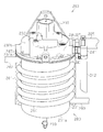
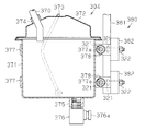
- the oil separator main body 303 is fixed to a frame 309 such as a ladder frame by bolts 321 and nuts 322 via a pair of plate-like attachment members 308. As shown in FIG. The oil separator body 303 and the expansion tank 304 are connected by a hose 370. One end of the hose 370 is connected to the drain outlet 317 of the oil separator main body 303.
- the expansion tank 304 includes a bottomed cylindrical main body container 371 for containing drain and a lid 372 for closing the opening of the main body container 371.
- a handle 373 for lifting the expansion tank 304 is attached to the main body container 371.
- the lid 372 is provided with a cylindrical inlet port 374 communicating with the inside.
- the other end of the hose 370 is connected to the inlet port 374.
- the inlet port 374 functions as an inlet for supplying drain to the expansion tank 304.
- the inlet port 374 is located below the drain discharge port 317. For this reason, when the drain accumulated in the drain reservoir 345 of the oil separator main body 303 reaches the drain discharge port 317, it is naturally transferred from the drain discharge port 317 through the hose 370 to the additional tank 304 by gravity.
- a cylindrical discharge port 375 communicating with the inside of the main body container 371 is provided on the lower surface of the main body container 371.
- a ball cock 376 that can open and close the communicating portion is attached to the discharge port 375. The ball cock 376 opens and closes the communicating portion by operating the lever 376a, and discharges and stops the drain.
- Two ⁇ -shaped attachment members 377 that are attached to the vehicle body are fastened and fixed to the main body container 371 of the expansion tank 304.
- a cylindrical spacer 378 is attached to the opening of the attachment member 377.
- Bolts 321 are inserted into the spacers 378 and mounting holes 377 a formed in the attachment member 377 and are fastened and fixed by nuts 322.
- the spacer 378 defines the tightening amount of the nut 322 with respect to the bolt 321.
- the attachment member 377 is fixed to a side guard 380 as an entrainment prevention member attached to the vehicle body 310 of the truck.
- the side guard 380 prevents an object from being caught in the space between the tires around the undercarriage.
- the side guard 380 includes a rectangular stay 381 that is fixed to the vehicle body 310 with bolts 321 and hangs down from the vehicle body 310, and a rectangular bar 382 that is welded to the stay 381 and extends in the extending direction of the vehicle body 310.
- the attachment member 377 attached to the expansion tank 304 is fixed to the bar 382 of the side guard 380 by bolts 321 and nuts 322.
- the drain accumulated in the casing 311 is heated by the heater 326, and the water in the drain is evaporated.
- the accumulated drain reaches the drain discharge port 317, it is naturally discharged from the drain discharge port 317 by gravity and transferred to the expansion tank 304 through the hose 370.
- Drain can be collected by placing a bucket or the like under the expansion tank 304.
- the amount of oil that can be separated and recovered by the oil separator main body 303 can be increased by the capacity of the expansion tank 304, so that the number of occurrences (occurrence frequency) of the collected drain collecting operation can be suppressed. Further, since the expansion tank 304 is attached to the side guard 380 so that the inlet port 374 is located below the drain discharge port 317 of the oil separator main body 303, the drain is naturally discharged from the drain reservoir 345 to the expansion tank 304 by gravity. It can be transferred, and the operator can easily collect the drain.
- the separated drain can be stored separately from the casing 311. For this reason, it is possible to increase the total amount of drain that can be stored, and thus to suppress the number of occurrences (occurrence frequency) of the collected operation of collecting the drain.
- the expansion tank 304 is attached to the side guard 380 provided in the vehicle. For this reason, since the expansion tank 304 is located in a place where the worker can reach, the operation of collecting the drain accumulated in the expansion tank 304 is easy.
- the sealing sheet 20 is provided between the opening 18 of the housing 4 and the lid 19, but the sealing sheet 20 may be omitted. In addition, it is desirable that a hermetic seal is maintained between the opening 18 of the housing 4 and the lid 19.
- the baffle plates 34b and 35b extending perpendicular to the standing plates 34a and 35a are provided. However, if the extremely narrow portion 36 can be maintained, the baffle plates 34b and 35b are raised. It is not necessary to form perpendicularly with respect to the installation plates 34a and 35a.
- the extremely narrow portion 36 including a pair of baffle plates 34b and 35b is provided.
- an extremely narrow portion including a plurality of pairs of baffle plates may be provided.
- the communication hole 33 is formed in the lower part of the partition wall 30.
- the communication hole 33 of the partition wall 30 is omitted. May be.
- the movement of the collision plates 34, 35, the partition wall 30, the urethane foam 38, the crashed aluminum 39, etc. is restricted by the lid 19.
- the collision plates 34 and 35, the partition wall 30, the urethane foam 38, the crashed aluminum 39, and the like are fixed, the movement may not be restricted by the lid 19.
- the crashed aluminum 39 is installed in the secondary expansion chamber 32, but urethane foam 38 may be installed in place of the crashed aluminum 39.
- the order of the members arranged in the housing 4 is as follows: urethane foam 38 ⁇ impact plate 34, 35 ⁇ partition wall 30 (orifice hole 30a) ⁇ impact plate 34, 35 ⁇ crashed Aluminum 39.
- these arrangements may be changed, some members may be omitted, some members may be increased, or the members may be changed. .
- the drain communication hole 46 is provided in a portion where the urethane foam 38 or the crashed aluminum 39 is in contact with the drain communication portion 45, the drain drop is promoted, and the drain expansion chamber 31 is provided. , 32 can be suppressed.
- the expansion chambers 31 and 32 are provided in the horizontal direction, but may be provided in the vertical direction.
- the introduction port 14 is formed on the front surface 12 and the discharge port 15 is formed on the back surface. However, if there is a space in the vertical direction, the upper cover 19 and the opening 16 may be provided. The introduction port 14 and the discharge port 15 may be formed.
- the attachment / detachment mechanism between the casing 4 and the drain reservoir 50 is the bolt 21 and the nut 22, but other configurations such as an engagement structure may be adopted.
- the attachment / detachment mechanism between the housing 4 and the drain communication portion 45 is an insertion structure, but other configurations such as an engagement structure may be adopted.
- the drain reservoir 50 is heated by the heater 41.
- the drain itself stored in the drain reservoir 50 may be directly heated.
- an insertion hole 53 for inserting the heater 41 is formed on the side surface of the drain reservoir 50, and the heater 41 is inserted from the insertion hole 53.
- the heater 41 directly heats the accumulated drain.
- the thermostat 42 is installed on the inner wall of the drain reservoir 50 in order to perform accurate temperature control. In this way, heat transfer from the heater 41 to the drain is high, and the drain can be heated more efficiently than indirectly heating the drain.
- the drain reservoir 50 may be omitted and the drain may be accumulated inside the housing 4.
- the heater 41 is provided on the rib 40 of the housing 4.
- the heater 41 is installed on the rib 52 (40), but the heater 41 may be installed at a place other than the rib 52 (40).
- the number of heaters 41 can be changed as necessary.
- the primary expansion chamber 31 and the secondary expansion chamber 32 have substantially the same size, that is, volume, but the volume of the secondary expansion chamber 32 is larger than the volume of the primary expansion chamber 31. May be increased. In this way, the saturated vapor pressure in the secondary expansion chamber 32 is further reduced and oil and water are likely to aggregate, and the mass of the particles is increased to easily collide with the collision plate. Therefore, more oil and water separated from the air can be stored in the secondary expansion chamber 32 than in the primary expansion chamber 31.
- the oil separator 3 is provided in the exhaust system of the air dryer 2 that is downstream of the compressor 1 of the air system.
- the oil separator 3 may be provided downstream of the air system compressor 1 and upstream of the air dryer 2. If it does in this way, an oil component can be isolate
- the oil separator 3 is provided in the air system in which the air dryer 2 is provided in a vehicle such as a truck, a bus, and a construction machine.
- the oil separator 3 is used for separating oil from air containing moisture. Can be used anywhere.
- the exhaust from the air dryer that dries the compressed air to the atmosphere in a factory or the like may be cleaned by an oil separator.
- the bolt 136 is fastened to the screw hole 132c as the attachment / detachment mechanism, but other attachment / detachment mechanisms may be employed.
- a clamp ring 110 that sandwiches the flange portion 132b of the lid 132 and the flange portion 131b of the case 131 and tightens the inner diameter side may be employed as the attachment / detachment mechanism.
- the clamp ring 110 includes a ring 111 having a U-shaped cross section that sandwiches the flange portions 132b and 131b, a bolt 113 and a nut 114 for tightening the tightening portion 112 of the ring 111.
- a concave-convex fitting structure may be employed as an attaching / detaching mechanism.
- a convex portion 115 protruding inside the case 131 is provided along the circumferential direction, and the concave portion 116 is provided instead of the flange portion 132 b of the lid 132.
- the case 131 is pressed toward the lid 132, and the convex portion 115 of the case 131 is fitted into the concave portion 116 of the lid 132.
- the case 131 may be provided with a recess, and the lid 132 may be provided with a protrusion. If the concave / convex fitting is employed, the case 131 can be attached to the lid 132 simply by fitting, so that it can be easily detached. Moreover, you may provide the set screw which prevents rotation with respect to the lid
- the heater 155 is inserted into the drain reservoir 154 through the insertion hole 156 and the drain is directly heated.
- the housing portion that houses the heater 155 in the case 131. 157 may be provided to heat the case 131. If it does in this way, the water
- the introduction port 135 and the discharge port 140 are provided on the surface in the horizontal direction of the lid 132, but the introduction port 135 and the discharge port 140 are provided on the vertical surface such as the upper portion of the lid 132. May be provided.
- the drain hose 134 is connected to the drain discharge port 133 of the case 131, but the drain hose 134 may be omitted and the drain hose 134 may be directly discharged.
- a drain outflow suppressing member is provided at the drain discharge port 133.
- the first expansion chamber 145, the second expansion chamber 151, and the third expansion chamber 159 are provided in the oil separator 103.
- the first expansion chamber 145, the second expansion chamber 151, and the third expansion chamber 159 are provided. It may be at least one with the expansion chamber 159.
- the drain hose 134 may be provided with a scale.
- a member such as a nonwoven fabric filter may be disposed upstream or downstream of the urethane foam 150 or in the expansion chambers 145, 151.
- static electricity may be applied to a member such as a urethane foam 150 such as a sponge or a nonwoven fabric filter.
- members can be charged with static electricity by a method such as utilizing a flow of dry air from a dryer.
- members, such as urethane foam 150, such as sponge, and a nonwoven fabric filter may be formed from the material electrically charged from the beginning. In this way, the oil component removal rate can be further improved.
- the urethane foam 150 is used as the impact material, but other members such as crashed aluminum may be used. Further, instead of the expansion chamber having the collision material, a simple expansion chamber having no collision material may be used.
- the jacket 281 is preferably a heat insulating material.
- the compressed air supplied from the compressor 1 is supplied to the air dryer 2 via the jacket 281 of the heating device 280. However, only a part of the compressed air supplied from the compressor 1 is heated. It may be routed through 280 jacket 281.
- the hot compressed air supplied from the compressor 1 is drawn into the jacket 281 of the heating device 280 to warm the case 231, but the exhaust discharged from the internal combustion engine is supplied to the heating device 280. May be. That is, as shown in FIG. 25, high-temperature exhaust discharged from the engine 204 as an internal combustion engine is supplied to the heating device 280. The exhaust from the engine 204 supplied to the heating device 280 is discharged to the exhaust system of the internal combustion engine.
- the case 231 and the jacket 281 may be integrated.
- the case 231 is warmed by supplying the compressed air of the compressor 1 or the exhaust of the engine 204 to the heating device 280.
- the case 231 may be warmed by electric heat without relying on warm air. That is, as shown in FIG. 26, the case 231 may be warmed by winding a heating wire 285 as an electric heating portion around the case 231 and covering it with a jacket 281. In this way, the oil separator 203 can be warmed even when the vehicle is not driven.
- the outer periphery of the case 231 is warmed by the heating device 280, but a heating device may be provided inside the case 231.
- a heating device may be provided inside the case 231.
- a guide pipe through which the compressed air of the compressor 1 passes is provided in the case 231.
- the exhaust of the engine 204 may be passed through this guide pipe.
- the amount of drain may be reduced by evaporating moisture contained in the drain accumulated in the drain reservoir 254 by a heating means (heating device). In this way, since the period during which the drain accumulates to the capacity limit can be extended, the drain discharge interval can be lengthened and the maintenance burden can be reduced.
- the inlet 235 of the oil separator 3 is positioned above the connection port of the purge air discharge cover 224 in the vertical direction. However, if it is not necessary to suppress the height in the vertical direction including the air dryer 2 and the oil separator 203, the inlet 235 of the oil separator 203 may be positioned below the connection port of the purge air discharge cover 224 in the vertical direction. Good.
- the tip of the drain hose 234 is positioned above the lid 232 of the oil separator 203.
- the tip of the drain hose 234 may be positioned below the lid 232 of the oil separator 203 as long as the drain can be prevented from leaking from the tip of the drain hose 234.
- the drain hose 234 is connected to the drain discharge port 233 of the case 231, but the drain hose 234 is omitted and a plug is provided in the drain discharge port 233, and the drain discharge port 233 is directly discharged. May be.
- the first expansion chamber 245, the second expansion chamber 251, and the third expansion chamber 259 are provided in the oil separator 203.
- the first expansion chamber 245, the second expansion chamber 251, and the third expansion chamber 259 are provided. It may be at least one with the expansion chamber 259. Further, four or more expansion chambers may be provided.
- a member such as a nonwoven fabric filter may be disposed upstream or downstream of the urethane foam 250 or in the expansion chambers 245 and 251.
- static electricity may be applied to a member such as a urethane foam 250 such as a sponge or a nonwoven fabric filter.
- members can be charged with static electricity by a method such as utilizing a flow of dry air from a dryer.
- members, such as urethane foam 250, such as sponge, and a nonwoven fabric filter may be formed from the material electrically charged from the beginning. In this way, the oil component removal rate can be further improved.
- the urethane foam 250 is used as the impact material, but other members such as crashed aluminum may be used. Further, instead of the expansion chamber having the collision material, a simple expansion chamber having no collision material may be used.
- the expansion tank 304 is attached to the side guard 380 that is an entrainment preventing member, but it is not limited to the entrainment prevention member, and may be attached to another member such as a side member or a ladder frame.
- the main body container 371 of the expansion tank 304 may be provided with a viewing window for confirming the drain capacity. In this way, the amount of drain accumulated in the expansion tank 304 can be visually confirmed.
- the hose 370 may be formed of a transparent material. In this way, it can be confirmed whether or not the drain is accumulated in the expansion tank 304 beyond its capacity.
- the structure inside the casing 311 of the oil separator main body 303 can be changed as appropriate.
- the main body container 371 of the expansion tank 304 may be covered with a heat insulating material 379 as shown in FIG. In this way, since the expansion tank 304 is covered with the heat insulating material, it is possible to suppress the moisture in the drain from freezing, and it is possible to prevent the drain from being difficult to be discharged due to the freezing.
- a pump 305 is provided between the oil separator body 303 and the expansion tank 304 to forcibly transfer the drain from the housing 311 to the expansion tank 304. May be. In this way, since the drain is sent from the drain reservoir 345 of the housing 311 to the expansion tank 304 by the pump 305, the drain can be reliably transferred from the housing 311 to the expansion tank 304.
- the expansion tank 304 is a cylindrical container, but the shape of the expansion tank 304 can be changed as appropriate according to the installation space and capacity. Further, the shape of the attachment member 377 can be changed as appropriate.
- the oil separator main body 303 is provided in the exhaust system of the air dryer 2 downstream of the air system compressor 1.
- the oil separator body 303 may be provided downstream of the air system compressor 1 and upstream of the air dryer 2. If it does in this way, an oil component can be isolate
- An additional tank 304 may be attached to the oil separators 3, 103, 203 in the first to fourth embodiments.
Landscapes
- Engineering & Computer Science (AREA)
- Mechanical Engineering (AREA)
- General Engineering & Computer Science (AREA)
- Chemical & Material Sciences (AREA)
- Chemical Kinetics & Catalysis (AREA)
- Separating Particles In Gases By Inertia (AREA)
Description
本発明は、機器を通過した空気に含まれる油分を分離するオイルセパレータに関する。
トラック、バス、建機等の車両は、エンジンと直結したコンプレッサから送られる圧縮空気を利用してブレーキやサスペンション等のシステムを制御している。この圧縮空気には、大気中に含まれる水分やコンプレッサ内を潤滑する油分が含まれている。この水分や油分を含む圧縮空気が各システム内に侵入すると、錆の発生やゴム部材(Oリング等)の膨潤を招き作動不良の原因となる。このため、エア系統のコンプレッサの下流には、圧縮空気中の水分や油分を除去するためのエアドライヤが設けられている(例えば、特許文献1参照)。
エアドライヤ内には、フィルタや、シリカゲル及びゼオライト等の乾燥剤が設けられている。エアドライヤは、圧縮空気から水分を除去する除湿作用と、乾燥剤に吸着させた水分を取り除き外部に放出することによって乾燥剤を再生する再生作用とを行う。
ところで、乾燥剤の再生時にエアドライヤから放出される空気には水分とともに油分も含まれるので、環境負荷を考慮してエア系統のコンプレッサの下流にオイルセパレータを設けることが考えられている。
衝突板方式のオイルセパレータは、水分や油分を含んだ空気を筐体内に設けられた衝突板に衝突させることによって気液分離を行うことで、前記空気から油分を回収し、清浄エアを排出する(例えば、特許文献2)。
上記のオイルセパレータは、空気から分離した油分を含む液体であるドレンを膨張室の底部に溜めている。このドレンには水分も含まれるため、空気から分離された水分が多い際には、ドレンが貯留量の限度まで溜まるまでの期間が短くなるので、ドレンの回収時期(回収サイクル)が短期化するおそれがある。そこで、ドレンの回収時期(回収サイクル)を長期化したオイルセパレータが求められていた。
本発明の目的は、ドレンの回収時期(回収サイクル)を長期化したオイルセパレータを提供することにある。
上記目的を達成するため、本発明の一態様では、空気の導入口を有する筐体と、前記筐体内に設けられた膨張室と、前記膨張室の下部を加熱する加熱装置と、を備えるオイルセパレータを提供する。前記オイルセパレータは、油分を含む空気を前記導入口を通じて前記筐体内に導入し、導入された空気から油分を分離して回収する。前記膨張室の横断面積は前記導入口の開口面積よりも大きい。
本発明の別の態様では、エアドライヤからのパージエアを導入するための導入口と清浄エアを排出するための排出口とが設けられた蓋と、鉛直方向に併設された複数の膨張室と、前記蓋に取り付けられる筐体と、前記蓋を前記筐体から着脱可能とする着脱機構と、を備えるオイルセパレータを提供する。前記オイルセパレータは、前記パージエアを筐体内に流入させ、衝突材に衝突させることによって、前記パージエアから油分を分離して油分を含むドレンを回収し、清浄エアを排出する。前記膨張室同士の間には、前記導入口から導入された前記パージエアを鉛直下方へ通過させる貫通孔が形成される。
本発明のさらに別の態様では、エアドライヤからのパージエアを導入するための導入口と清浄エアを排出するための排出口とが設けられた筐体と、前記筐体内に設けられた膨張室と、前記筐体を暖める暖房装置と、を備えるオイルセパレータを提供する。前記オイルセパレータは、前記パージエアを筐体内に流入させ、前記パージエアから油分を分離して油分を含むドレンを回収し、清浄エアを排出する。
本発明のまたさらに別の態様では、空気の導入口及びドレン排出口を有する筐体と、
前記筐体内に設けられた衝突材と、を備えるオイルセパレータを提供する。前記オイルセパレータは、油分を含む空気を前記導入口を通じて前記筐体内に導入し衝突材に衝突させることによって、導入された空気から油分を分離して回収する。前記オイルセパレータは、前記ドレン排出口に接続され、前記筐体内に溜まったドレンを溜めるための増設タンクをさらに備える。
前記筐体内に設けられた衝突材と、を備えるオイルセパレータを提供する。前記オイルセパレータは、油分を含む空気を前記導入口を通じて前記筐体内に導入し衝突材に衝突させることによって、導入された空気から油分を分離して回収する。前記オイルセパレータは、前記ドレン排出口に接続され、前記筐体内に溜まったドレンを溜めるための増設タンクをさらに備える。
(第1の実施形態)
以下、本発明のオイルセパレータをエアドライヤの排気系統に具体化した第1の実施形態について図1~図6を参照して説明する。
以下、本発明のオイルセパレータをエアドライヤの排気系統に具体化した第1の実施形態について図1~図6を参照して説明する。
図1に示されるように、トラック、バス、建機等の車両は、コンプレッサ1から送られる圧縮空気を利用してブレーキやサスペンション等のシステムを制御している。このため、エア系統のコンプレッサ1の下流には、圧縮空気中の油水分を除去し、乾燥された空気を提供するためのエアドライヤ2が設けられている。エアドライヤ2内には、乾燥剤が設けられている。エアドライヤ2は、圧縮空気から油水分を除去する除湿作用と、乾燥剤に吸着させた油水分を取り除き外部に放出することによって乾燥剤を再生する再生作用とを行う。
本実施例では、乾燥剤の再生時にエアドライヤ2から放出される空気(パージエア)には水分とともに油分も含まれるので、環境負荷を考慮してエア系統のコンプレッサ1の下流にオイルセパレータ3を設ける。特に、オイルセパレータ3は、エアドライヤ2の排気系統に設けられ、エアドライヤ2内の乾燥剤を再生する際に排出されるパージエアから油水分を分離して回収する。
オイルセパレータ3は衝突板方式のオイルセパレータであり、その筐体内には、油水分を含んだ空気が衝突する複数の衝突板が設けられている。この衝突板方式のオイルセパレータ3は、油水分を含んだ空気を衝突板に衝突させて気液分離を行うことによって空気から油分を回収し、清浄エアを排出する。
図2に示されるように、オイルセパレータ3は、水平方向に延出した直方体状の筐体4を備える。筐体4の長手方向の対向する正面5と背面6とには、導入口7と排出口8とがそれぞれ形成されている。すなわち、図2では、左側から右側へ空気がオイルセパレータ3を通過する。
筐体4の底面には開口部16が形成されている。筐体4の底面には空気から分離したドレンを溜めるためのドレン溜め部50がボルト21とナット22とによって取り付けられている。ここで、ドレンとは油分と水分とを含む液体である。ドレン溜め部50は、上方に向けて開口する箱状である。なお、ボルト21とナット22とが着脱機構を構成している。
また、筐体4の底面の開口部16には、ドレン連通部45が嵌装されている。ドレン連通部45には、筐体4の内部をドレン溜め部50に連通するドレン連通孔46が複数形成されている。なお、ドレン連通部45と開口部16とが着脱機構を構成している。また、ドレン溜め部50の底面51において背面6寄りの部分には、ドレンを排出するドレン排出口17が形成されている。
また、筐体4の上面には開口部18が形成されている。開口部18は、長方形状の蓋19によって閉蓋されている。開口部18と蓋19との間には、開口部18の全面を覆う密閉シート20が挟まれている。蓋19と密閉シート20と筐体4とは、複数のボルト21とナット22によって締め付け固定されている。蓋19は、筐体4内に収容される部材の移動を規制する。
図3に示されるように、筐体4内の長手方向における中央部分には、板状の隔壁30が設けられている。筐体4の内部は、隔壁30によって、導入口14寄りの一次膨張室31と、排出口15寄りの二次膨張室32とに水平方向において区画されている。一次膨張室31と二次膨張室32との横断面積は各々、導入口7の横断面積よりも大きく形成されている。ここでの横断面積は、筐体4の長手方向に垂直な断面における面積に相当する。このため、膨張室内に導入された空気は膨張するので、膨張室を通過する速度が遅くなる。空気の通過速度が遅くなることによって、さらに、飽和蒸気圧が低下する。そのため、油水分が凝集し易くなり、油水分の粒子の質量が増加して衝突板に衝突し易くなる。
隔壁30の上部には、貫通孔(オリフィス孔)30aが一箇所形成されている。よって、この隔壁30は、オリフィス孔30aによって一次膨張室31から二次膨張室32への空気の流れを制御するオリフィスとして機能する。また、隔壁30の開口部16近傍の下部には、連通孔33が一箇所形成されている。連通孔33は、空気から分離して回収したドレンを膨張室31,32間で通過させる。
また、筐体4内の隔壁30の両側には、対向する一対の衝突板34,35がそれぞれ設けられている。上流側の第1衝突板34は、筐体4の開口部16から蓋19まで延出する第1立設板34aと、筐体4の長手方向において排出口8に向かって第1立設板34aから垂直に延出する第1邪魔板34bとを備えている。第1立設板34aは、第1邪魔板34bへの接続部よりも下方に衝突板34,35の幅方向に延びる長方形状の第1貫通孔34cを有する。
また、下流側の第2衝突板35は、筐体4の開口部16から蓋19まで延出する第2立設板35aと、筐体4の長手方向において導入口7に向かって第2立設板35aから垂直に延出する第2邪魔板35bとを備えている。第2立設板35aは、第2邪魔板35bへの接続部よりも上方に衝突板34,35の幅方向に延びる長方形状の第2貫通孔35cを有する。
第1邪魔板34bと第2邪魔板35bとは、空気の流路を邪魔するように突出しており、互いの大きい面を近接させることでそれらの面同士の間に狭い隙間である極狭部36が形成されている。ここで、第1邪魔板34bが第2邪魔板35bよりも蓋19寄りに位置している。極狭部36によって空気の通過速度が速くなり、さらに流路を蛇行させることにより油水分粒子の板への衝突機会が増加するので、空気から油水分が一層よく分離される。また、邪魔板34b,35bがあることにより、第1衝突板34と第2衝突板35との間を通過中に落下した油水分が、第1衝突板34と第2衝突板35との間を通過するエアによって再び上昇させられたり巻き上げられたりして第2貫通孔35cを通じて下流側へ運ばれることが抑制される。そのため、ドレンの採取量の減少を抑制できる。第1衝突板34及び第2衝突板35の開口部16近傍の下部には、それぞれ連通孔33が一箇所形成されている。連通孔33は、空気から分離して回収したドレンを通過させる。
一次膨張室31内部の空間には、一対の衝突板34,35が設けられている。導入口7と一対の衝突板34,35との間には、スポンジ等のウレタンフォーム38が設置されている。ウレタンフォーム38の前記衝突板34に対向する面には、複数の孔が開いたパンチングメタル板37が取り付けられている。ウレタンフォーム38は空気に含まれる油水分を捕獲する。
また、二次膨張室32内部の空間にも、一対の衝突板34,35が設けられている。一対の衝突板34,35と排出口8との間には、クラッシュドアルミ39が設置されている。クラッシュドアルミ39のそれぞれ前記衝突板34,35に対向する面には、複数の孔が開いたパンチングメタル板37が取り付けられている。すなわち、クラッシュドアルミ39は一対のパンチングメタル板37に挟まれている。クラッシュドアルミ39は空気に含まれる油水分を捕獲する。
各膨張室31,32には、筐体4の強度を高めるリブ40がそれぞれ設けられている。ドレン溜め部50には、強度を高めるためのリブ52が4箇所設けられている。ドレン連通部45のドレン連通孔46は、各膨張室31,32に二つずつ形成され、ウレタンフォーム38、各衝突板34,35、クラッシュドアルミ39のそれぞれに対応している。
図4に示されるように、ドレン連通部45とドレン溜め部50とは、筐体4に着脱可能である。すなわち、筐体4の開口部16にドレン連通部45を嵌着し、筐体4の底面にドレン溜め部50を装着する。このため、ドレン連通部45とドレン溜め部50とを筐体4から取り外すことで、ドレン連通部45とドレン溜め部50とに溜まったドレンを容易に取り除くことができる。
図5に示されるように、筐体4の下部に取り付けられたドレン溜め部50は、中空であって、ドレンの液面がドレン連通部45の下面に達するまでドレンを溜めることができる。
図6に示されるように、ドレン溜め部50のリブ52の底面51寄りには、加熱手段(加熱装置)としてのヒータ41を収容するための円柱状の収容部23が形成されている。ドレン溜め部50の外面にはヒータ41を挿入するための挿入口24が形成され、挿入口24は収容部23に貫通している。ヒータ41は、円柱状であって、ドレン溜め部50の外面から収容部23に挿入されている。ヒータ41は、電源に接続されている。
また、ドレン溜め部50の外面の挿入口24の上方には、サーモスタット42を取り付ける取付穴25が形成されている。サーモスタット42は、取付穴25に取り付けられ、電源とヒータ41とに接続されている。サーモスタット42は、ドレン溜め部50の温度を検出して、検出した温度に基づきヒータ41の加熱を制御する。ヒータ41によってドレン溜め部50を加熱することによって、ドレン溜め部50の底面に溜まったドレンに含まれる水分は極力蒸発させられるので、高い濃度で油分を含むドレンを生成する。
次に、前述のオイルセパレータの作用について説明する。
導入口7から一次膨張室31内に導入された空気は、ウレタンフォーム38によって油水分を捕獲されながらウレタンフォーム38を通過して、一次膨張室31の第1衝突板34の第1貫通孔34cを通過する。このとき、第1立設板34aに衝突した油水分が空気から分離される。第1貫通孔34cを通過した空気は、第1邪魔板34bと第2邪魔板35bとによって形成された極狭部36に向かい、極狭部36を通過する。このとき、第2立設板35aと第2邪魔板35bとに衝突した油水分が空気から分離される。
ウレタンフォーム38によって捕獲された水分と油分とを含むドレンは、ウレタンフォーム38内を伝って移動する。このドレンがウレタンフォーム38の下方に位置するドレン連通孔46からドレン溜め部50に落下して、ドレン溜め部50に溜まる。一次膨張室31の第1衝突板34に衝突して分離されたドレンは、第1衝突板34の連通孔33を通過して、衝突板34,35の下方に位置するドレン連通孔46からドレン溜め部50に落下して、ドレン溜め部50に溜まる。
極狭部36を通過した空気は、第2立設板35aの第2貫通孔35cを通過して隔壁30のオリフィス孔30aに向かい、オリフィス孔30aを通過する。このとき、隔壁30に衝突した油水分が空気から分離される。一次膨張室31の第2衝突板35に衝突して分離されたドレンは、第2衝突板35の連通孔33を通過して、衝突板34,35の下方に位置するドレン連通孔46からドレン溜め部50に落下して、ドレン溜め部50に溜まる。
隔壁30のオリフィス孔30aを通過した空気は、二次膨張室32の第1立設板34aの第1貫通孔34cを通過する。このとき、第1立設板34aに衝突した油水分が空気から分離される。第1貫通孔34cを通過した空気は、第1邪魔板34bと第2邪魔板35bとによって形成された極狭部36に向かい、極狭部36を通過する。このとき、第2立設板35aと第2邪魔板35bとに衝突した油水分が空気から分離される。
隔壁30に衝突して分離されたドレンは、隔壁30の連通孔33と二次膨張室32の第1衝突板34の連通孔33を通過して、衝突板34,35の下方に位置するドレン連通孔46からドレン溜め部50に落下して、ドレン溜め部50に溜まる。
極狭部36を通過した空気は、第2立設板35aの第2貫通孔35cを通過してクラッシュドアルミ39に向かい、クラッシュドアルミ39を通過する。このとき、クラッシュドアルミ39に導入された空気は、クラッシュドアルミ39によってさらに油水分を捕獲されながらクラッシュドアルミ39を通過して、油分を含まない清浄エアが排出口15から外部に排出される。
二次膨張室32の第1衝突板34に衝突して分離されたドレンは、第1衝突板34の連通孔33を通過して、衝突板34,35の下方に位置するドレン連通孔46からドレン溜め部50に落下して、ドレン溜め部50に溜まる。二次膨張室32の第2衝突板35に衝突して分離されたドレンは、第2衝突板35の連通孔33を通過して、衝突板34,35の下方に位置するドレン連通孔46からドレン溜め部50に落下して、ドレン溜め部50に溜まる。クラッシュドアルミ39によって捕獲されたドレンは、クラッシュドアルミ39内を伝って移動し、クラッシュドアルミ39の下方に位置するドレン連通孔46からドレン溜め部50に落下して、ドレン溜め部50に溜まる。
ドレン溜め部50に溜まったドレンは、ヒータ41によって加熱される。これによって、ドレン内の水分が蒸発させられる。高い濃度で油分を含むドレンがドレン排出口17から排出される。ドレン溜め部50内に溜まったドレンを除去する際には、筐体4からドレン溜め部50を取り外すことでドレン溜め部50の内部を洗浄できる。
以上、説明した実施形態によれば、以下の利点を得ることができる。
(1)膨張室31,32の下部にヒータ41を備えたので、衝突板34,35に衝突して膨張室31,32の下部に溜まった油分及び水分を含むドレンがヒータ41によって加熱される。したがって、ドレン中の水分を蒸発させることができる。よって、溜まったドレンから水分を減らすことで油分の濃度を高め、ドレンの貯留量を減らすことができ、ひいてはドレンの回収時期(回収サイクル)を長期化することができる。さらに、ヒータ41によって筐体4を加熱することによって、寒冷地においても、ドレンの凍結によりドレンをドレン排出口17から排出できない状態になることを防止することができる。
(2)筐体4の下部に設けられた収容部23にヒータ41が収容されている。ヒータ41は筐体4を加熱するので、油分と水分とを含むドレンによってヒータ41が劣化することを抑制することができる。
(3)ボルト21とナット22による着脱機構によってドレン溜め部50が筐体4から取り外しできるので、筐体4から取り外された状態でドレン溜め部50を洗浄することができる。特に、ドレン溜め部の内壁に油分が付着した際における油分の除去が容易となる。また、ドレン溜め部を使い捨てにすれば、ドレンを容易に回収することができる。
(第2の実施形態)
以下、本発明のオイルセパレータをエアドライヤの排気系統に具体化した第2の実施形態について、図7及び図8を参照して説明する。この実施形態のオイルセパレータは、ドレン溜め部に溜められたドレンから水分を分離してから、分離した水分をヒータで加熱する点において上記第1の実施形態と異なっている。以下、第1の実施形態との相違点を中心に説明する。なお、この実施形態のオイルセパレータは、図1に示す第1の実施形態のオイルセパレータとほぼ同様に構成されている。
以下、本発明のオイルセパレータをエアドライヤの排気系統に具体化した第2の実施形態について、図7及び図8を参照して説明する。この実施形態のオイルセパレータは、ドレン溜め部に溜められたドレンから水分を分離してから、分離した水分をヒータで加熱する点において上記第1の実施形態と異なっている。以下、第1の実施形態との相違点を中心に説明する。なお、この実施形態のオイルセパレータは、図1に示す第1の実施形態のオイルセパレータとほぼ同様に構成されている。
図7に示されるように、筐体4の下部には、回収したドレンを溜める第1ドレン受け55が設けられている。第1ドレン受け55の底部は、筐体4の長手方向に沿って二次膨張室32に近づくほどの鉛直方向における深さが深くなるように傾斜している。第1ドレン受け55の二次膨張室32寄りの外面には、箱状の第2ドレン受け57が設けられている。第1ドレン受け55は第2ドレン受け57にそれらの底面近くにおいて連通している。このため、ドレンに含まれる水分のみが連通部分を通じて第1ドレン受け55から第2ドレン受け57に移動する。前記連通部分には油分の侵入を防ぐドレンフィルタ56が設置されている。第2ドレン受け57の底面近くには、ドレンを加熱するためのヒータ41が設置されている。第2ドレン受け57の上面には、水分のみが外部に排出されるように水蒸気のみを通す水蒸気フィルタ58が設置されている。
第1ドレン受け55においてドレンに含まれる水分と油分とが分離し難い場合には、第1ドレン受け55に分離試薬を投入して、油分を分離させることが望ましい。
次に、前述のように構成されたオイルセパレータ3の作用について図8を参照して説明する。
図8に示されるように、一次膨張室31、衝突板34,35、二次膨張室32を通じて空気から油分が分離されることによって、油分を含まない洗浄エアが外部に排出される。一次膨張室31、衝突板34,35、二次膨張室32によって空気から分離して回収されたドレンは、第1ドレン受け55に溜められる。
第1ドレン受け55に溜められたドレンは、相対的に高い濃度で油分を含んでいる。ドレン中において水分と油分とが分離すると油分が上方へ移動して、水分が下方へ移動する。第1ドレン受け55に溜められたドレンは、ドレンフィルタ56を通過して第2ドレン受け57に移動する。第2ドレン受け57に溜められたドレンは、水分が下方へ移動しているので、相対的に低い濃度で油分を含む。
第2ドレン受け57に溜められたドレンは、ヒータ41によって加熱され、ドレン中の水分が蒸発させられる。ヒータ41の加熱によって発生した水蒸気は、水蒸気フィルタ58を介して外部に排出される。
以上、説明した実施形態によれば、第1の実施形態の(1)~(3)の利点に加え、以下の利点を得ることができる。
(4)第1ドレン受け55においてドレンから水分のみを分離して、この分離した水分をヒータ41で蒸発させる。したがって、水分を蒸発させるために必要な熱量を抑制することができる。
(第3の実施形態)
以下、図11~図17を参照して、オイルセパレータの第3の実施形態について説明する。
以下、図11~図17を参照して、オイルセパレータの第3の実施形態について説明する。
図11に示されるように、エアドライヤ2は、鉛直上方が閉じた有底円筒状のケース121と、当該ケース121の開口部を閉蓋するとともにケース121を支持する支持部材122とを備えている。支持部材122の下部には、乾燥剤の再生時にパージエアを排出するパージエア排出口123が形成されている。パージエア排出口123には、接続ホース125が接続されるパージエア排出カバー124が取り付けられている。接続ホース125は、オイルセパレータ103に接続されている。なお、エアドライヤ2の支持部材122には、コンプレッサ1で圧縮された圧縮空気を導入する導入口(図示略)が設けられるとともに、乾燥された圧縮空気を排出する排出口(図示略)が設けられている。
オイルセパレータ103は、鉛直方向に延出した有底円筒状の筐体としてのケース131と、当該ケース131の開口部を閉蓋する蓋132とを備えている。ケース131の底部131aには、溜まったドレンを排出するためのドレン排出口133が設けられている。ドレン排出口133には、ドレンを取り出す際に使用するドレンホース134が接続されている。蓋132には、接続ホース125を介してエアドライヤ2からのパージエアを導入するための導入口135と、油分を分離した清浄エアを排出するための排出口140とが別々に形成されている。導入口135と接続ホース125とは、連結部材127によって接続されている。
オイルセパレータ103の蓋132には、取付部材137が一体に蓋132に対して立設されている。取付部材137は、ボルト139によってシャーシ138に固定されている。
ドレンホース134の先端部は、車両のシャーシ138等に固定された支持部材190に着脱可能に取り付けられている。すなわち、支持部材190には、固定部材191が固定されている。この固定部材191の下端部には、ドレンホース134の先端部をワンタッチで取り付け可能なワンタッチカプラ192が固定されている。ドレンホース134は、ドレンホース134の先端部をワンタッチカプラ192に挿入することによって固定部材191に固定され、ワンタッチカプラ192を操作することによって固定部材191から取り外せる。ドレンホース134の先端部は、鉛直方向上向きに固定部材191に装着される。
オイルセパレータ103の排出口140には、水平方向から鉛直上方へ曲がって延びるエルボ部材160が螺着されている。エルボ部材160の先端には、液垂防止部材170が取り付けられるとともに、ごみ等の侵入を防ぐカバー180が取り付けられている。
図12に示されるように、蓋132には、導入口135と排出口140とが同一方向(図中右側)に開口している。導入口135と排出口140とは、水平方向における面にそれぞれ設けられている。導入口135には、連結部材127を介して接続ホース125が接続されている。排出口140には、エルボ部材160が接続されている。つまり、連結部材127とエルボ部材160とが併設されている。
図13に示されるように、蓋132は、鉛直上方が閉じた有底円筒状である。蓋132の導入口135の近傍の内壁には、導入口135から導入されたパージエアの進行方向に対して直交するよう2枚の邪魔板146が立設されている。蓋132の内部空間は、導入口135から導入されたパージエアを膨張させる第1膨張室145として機能する。第1膨張室145内に形成されるパージエアの経路の横断面積は、導入口135の横断面積よりも大きい。ここでの横断面積は、パージエアの進行方向に垂直な断面における面積に相当する。蓋132には、ケース131内から排出口140に連通する連通部132aが形成されている。
図14及び図15に示されるように、ケース131と蓋132との間には、ケース131を閉蓋するとともに、蓋132の開口部を閉蓋する円盤状のカバー147が設けられている。カバー147は、ケース131と一緒に蓋132にボルト136によって締結されている。すなわち、蓋132に設けられたフランジ部132bに形成されたねじ孔132cにボルト136が締結される。ボルト136とねじ孔132cとが着脱機構として機能する。また、ケース131に設けられたフランジ部131bに形成された貫通孔にボルト136の螺子部が貫通される。カバー147には、ボルト136のねじ部が貫通する貫通孔が形成されている。よって、ケース131のフランジ部131bの貫通孔とカバー147のフランジ部147aの貫通孔とにボルト136のねじ部を貫通させて、蓋132のフランジ部132bのねじ孔132cにボルト136を螺着することで、蓋132とカバー147とケース131とが締結されている。ケース131は、ボルト136をねじ孔132cから外すことで蓋132から取り外すことができる。カバー147には、ケース131内から排出口140へ連通する連通孔147cが形成されている。
蓋132とカバー147とによって形成された空間が第1膨張室145として機能する。カバー147には、鉛直上方が閉じた有底円筒状の収容部材148がボルト136によって固定されている。収容部材148は、スポンジ等のウレタンフォーム150を収容する。なお、ウレタンフォーム150が衝突材として機能する。収容部材148の上端縁部と下端縁部とには、フランジ部148aとフランジ部148bとが形成されている。収容部材148の上端縁部に形成されたフランジ部148aにボルト136が貫通されて、収容部材148がカバー147に締結されている。カバー147と収容部材148の上面とによって形成された空間が第2膨張室151として機能する。カバー147には、第1膨張室145を第2膨張室151に連通させる複数の貫通孔147bが形成されている。収容部材148の上底部149の中央部分には、複数の貫通孔149aが形成されている。カバー147の貫通孔147bと収容部材148の上底部149の貫通孔149aとは対向しない位置に形成されている。収容部材148の側面の下端部側には、複数の貫通孔148cが径方向に間隔をおいて形成されている。
収容部材148の下端縁部に形成されたフランジ部148bには、円盤状の支持蓋152がねじ153によって固定されている。支持蓋152は、収容部材148内に収容されたウレタンフォーム150を支持する。支持蓋152の内径は、ケース131の内径とほぼ同じである。収容部材148の上底部149と支持蓋152とによって形成された空間が第3膨張室159として機能する。支持蓋152には、ウレタンフォーム150によって除去された油水分を落下させる複数の貫通孔152aが形成されている。よって、ケース131内の下部がドレン溜め部154として機能する。
ドレン溜め部154には、溜まったドレンを加熱して、ドレン中の水分を蒸発させるための加熱装置としてのヒータ155が設置されている。ヒータ155は、ケース131の側面に形成された挿入孔156からケース131内に挿入されている。ヒータ155は、ドレン溜め部154に溜まったドレンを直接加熱する。ヒータ155の加熱は、図示しないサーモスタットによって制御される。
図16及び図17に示されるように、エルボ部材160は、水平方向に延びる水平部161と、水平部161に連続して垂直方向に延びる垂直部162とを備えている。エルボ部材160の基端部には、排出口140の雌螺子部140aに螺着する雄螺子部163が形成されている。エルボ部材160の雄螺子部163は、排出口140の雌螺子部140aに螺着された際に、エルボ部材160の先端が上方に向く位置で締結が止まるように形成されている。エルボ部材160の先端部には、液垂防止部材170を螺着する雌螺子部164が形成されている。エルボ部材160内にドレンが流れ込んだ際には、垂直部162によってドレンが外部に流れ出すことが抑制される。
液垂防止部材170の内部には、基端と先端とを繋ぐ貫通孔171が形成され、大きな異物が流路に進入して流路を塞ぐことを防止する4枚の区画板172が設けられている。区画板172は、周方向において均等な間隔で軸方向に延出して形成されている。貫通孔171の中心であって区画板172同士の交差する部分には、円筒部173が形成されている。液垂防止部材170の基端部には、エルボ部材160の雌螺子部164に螺着される雄螺子部174が形成されている。液垂防止部材170の先端の開口部175の側面には、開口部175から垂れた液体を受ける液垂受部176が全周に亘って形成されている。この液垂受部176の底部には、液垂受部176に受けた液体を貫通孔171に戻す戻し部としての戻し孔177が形成されている。戻し孔177は、液垂受部176から貫通孔171まで貫通している。よって、液垂受部176に垂れた液体は、戻し孔177を介してエルボ部材160へ戻ることとなる。
カバー180の内側には、液垂防止部材170の円筒部173に差し込まれる円柱状の挿込部181が突設されている。挿込部181には段差部182が形成されている。段差部182によって、液垂防止部材170に対するカバー180の挿込位置が設定されている。カバー180は、液垂防止部材170の開口部175を覆っている。カバー180の外径は、液垂受部176の内径よりも小さい。よって、液垂防止部材170を通過した清浄エアは、液垂防止部材170の開口部175とカバー180の内面との間を通過して外部に排出される。
次に、前述のオイルセパレータ103の作用について説明する。
図11に示されるように、エアドライヤ2から排出されたパージエアがオイルセパレータ103に導入される。パージエアは、油水分を含む空気である。
図13に示されるように、導入口135から導入されたパージエアは、邪魔板146に衝突して邪魔板146に沿ってオイルセパレータ103内に導入され、第1膨張室145内で膨張する。
図14に示されるように、第1膨張室145内で膨張した空気は、カバー147に形成された貫通孔147bを介して第2膨張室151に進入する。第2膨張室151内で膨張した空気は、収容部材148の上底部149の貫通孔149aを介して第3膨張室159内に進入する。このとき、ウレタンフォーム150に衝突した油水分が空気から分離される。ウレタンフォーム150によって捕獲された水分と油分とを含むドレンは、ウレタンフォーム150内を伝って移動する。このドレンが支持蓋152の上面に達し、支持蓋152の貫通孔152aからドレン溜め部154に落下して、ドレン溜め部154に溜まる。ドレン溜め部154に溜まったドレンは、ドレン排出口133からドレンホース134内に進入する。ドレン溜め部154に溜まったドレンは、ヒータ155によって加熱される。これによって、ドレン内の水分が蒸発させられる。
ところで、ドレンホース134の先端部を固定部材191から取り外すと、大気が固定部材191内に流入して、ドレンホース134内のドレンがドレン溜め部154のドレンと同じ高さに位置する。よって、ドレンホース134内のドレンを視認することによって、ドレン溜め部154のドレンの量を確認することができる。
一方、図15に示されるように、収容部材148の上底部149の貫通孔149aから第3膨張室159内に進入して油水分が分離された空気は、収容部材148の側面の貫通孔148cからケース131内に進入する。ケース131内に進入した空気は、カバー147の連通孔147cと蓋132の連通部132aとを通過して排出口140からエルボ部材160に流入して大気に排出される。よって、ケース131内に進入した空気は、ドレン溜め部154のドレンにほとんど触れることなく、排出口140から排出される。排出口140から排出される空気は、油分を含まない清浄エアである。
ドレン溜め部154に溜まったドレンを排出する際には、ワンタッチカプラ192を操作することによってドレンホース134の先端部をワンタッチカプラ192から取り外して、ドレンホース134の先端部をドレン溜め部154のドレンの水面よりも低くする。これによって、ドレン溜め部154からドレンを排出できる。
ケース131内を洗浄する際や衝突材としてのウレタンフォーム150を交換する際には、ボルト136をねじ孔132cから外すことによって、蓋132からケース131とカバー147とを取り外す。取り外したケース131とカバー147とを洗浄することができる。また、収容部材148に支持蓋152を固定しているねじ153を外し、ウレタンフォーム150を収容部材148内から取り出し、ウレタンフォーム150を交換する。交換後には、ねじ153によって支持蓋152を収容部材148に固定し、ボルト136を蓋132のねじ孔132cに締結することによって、蓋132にケース131とカバー147とを取り付ける。
以上、説明した第3の実施形態によれば、以下の利点を得ることができる。
(1)導入口135と排出口140とが蓋132に設けられ、導入口135からケース131内に導入されたパージエアが鉛直下方へ複数の膨張室145,151,159を通過して排出口140から清浄エアが排出される。着脱機構としてのボルト136とねじ孔132cとによってケース131を蓋132から取り外したり、取り付けたりできる。このため、ケース131を蓋132から取り外すことで筐体を容易に分離することができる。
(2)導入口135と排出口140とが蓋132の水平方向の面にそれぞれ設けられる。このため、ケース131には導入口135や排出口140が設けられないので、蓋132からケース131を取り外す際にケース131に接続された管等がなく取り外しが容易である。また、蓋132の鉛直方向において上面や底面に管を接続することがないので、鉛直方向の長さを抑制することができる。
(3)ケース131の下部に設けられた挿入孔156からヒータ155が挿入されて、ヒータ155がドレンを直接加熱する。このため、ドレンに含まれる水分を蒸発させて、ドレンの量を減らすことができる。これによって、ケース131を蓋132から取り外す回数を抑制でき、着脱機構の耐用期間を長くできる。また、ヒータ155からドレンへの熱伝達が高く、ドレンを間接的に加熱するよりも効率良く加熱することができる。
(第4の実施形態)
以下、図21~図24を参照して、オイルセパレータの第4の実施形態について説明する。
以下、図21~図24を参照して、オイルセパレータの第4の実施形態について説明する。
オイルセパレータ203には、暖房装置280が設けられている。暖房装置280は、コンプレッサ1から供給される高温の圧縮空気をオイルセパレータ203の外周を通過させることによってオイルセパレータ203を暖める。すなわち、コンプレッサ1の圧縮空気は、オイルセパレータ203の外周を経由してエアドライヤ2に供給される。コンプレッサ1から供給される圧縮空気の温度は160℃ほどの高温である。
図21に示されるように、エアドライヤ2は、鉛直上方が閉じた有底円筒状のケース221と、当該ケース221の開口部を閉蓋するとともにケース221を支持する支持部材222とを備えている。支持部材222の下部には、乾燥剤の再生時にパージエアを排出するパージエア排出口223が形成されている。パージエア排出口223には、接続ホース225が接続されるパージエア排出カバー224が取り付けられている。接続ホース225は、オイルセパレータ203に接続されている。なお、エアドライヤ2の支持部材222には、コンプレッサ1で圧縮された圧縮空気を導入する導入口228が設けられるとともに、乾燥された圧縮空気を排出する排出口229が設けられている。
オイルセパレータ203は、鉛直方向に延出した有底円筒状の筐体としてのケース231と、当該ケース231の開口部を閉蓋する蓋232とを備えている。ケース231の底部231aには、溜まったドレンを排出するためのドレン排出口233が設けられている。ドレン排出口233には、ドレンを取り出す際に使用するドレンホース234が接続されている。蓋232には、接続ホース225を介してエアドライヤ2からのパージエアを導入するための導入口235と、油分を分離した清浄エアを排出するための排出口240とが別々に形成されている。導入口235と接続ホース225とは、連結部材227によって接続されている。
オイルセパレータ203の蓋232には、取付部材237が一体に蓋232に対して立設されている。取付部材237は、ボルトによってシャーシ238に固定されている。
ドレンホース234の先端部は、車両のシャーシ238等に固定された支持部材260に着脱可能に取り付けられている。すなわち、支持部材260には、固定部材261が固定されている。この固定部材261の下端部には、ドレンホース234の先端部をワンタッチで取り付け可能なワンタッチカプラ262が固定されている。ドレンホース234は、ドレンホース234の先端部をワンタッチカプラ262に挿入することによって固定部材261に固定され、ワンタッチカプラ262を操作することによって固定部材261から取り外せる。ドレンホース234の先端部は、鉛直方向上向きに固定部材261に装着される。ドレンホース234の先端は、オイルセパレータ203の蓋232よりも上方に位置している。このため、ドレンホース234の先端からドレンが漏れることを抑制できる。
オイルセパレータ203のケース231の外周には、暖房装置280を構成する円筒状のジャケット281が装着されている。ジャケット281は、ケース231に対して着脱可能である。ジャケット281の側面上部には、コンプレッサ1と接続して、コンプレッサ1から圧縮空気を導入するための導入接続管282が接続されている。ジャケット281の側面下部には、エアドライヤ2と接続して、エアドライヤ2に圧縮空気を排出するための排出接続管283が接続されている。排出接続管283は、エアドライヤ2の導入口228に接続されている。暖房装置280は、コンプレッサ1の圧縮空気をジャケット281内に引き込むことによってケース231を暖める。また、暖房装置280は、コンプレッサ1から供給される圧縮空気の熱量をジャケット281を介してケース231に移動させることによって、コンプレッサ1から供給された圧縮空気を冷却してエアドライヤ2に排出する。ジャケット281を通過して冷却された圧縮空気の温度は60℃ほどである。
図22に示されるように、ジャケット281には、ケース231の外周に沿って螺旋状に延びる誘導管284が設けられている。誘導管284は導入接続管282を排出接続管283に繋いでいる。蓋232に設けられた導入口235及び排出口240は、同一方向(図中右側)に開口している。導入口235には、連結部材227を介して接続ホース225が接続されている。排出口240には、水平方向から鉛直下方へ曲がって延びる接続部材241を介して排出ホース242が接続されている。つまり、連結部材227と接続部材241とが併設されている。排出ホース242の先端開口部は、ケース231寄りの部分の鉛直方向における長さがその対向する部分における長さより短く形成されており、先端開口部の端面は水平方向に対し斜めに形成されている。これによって、排出ホース242からの清浄エアの排出を容易にしながら、防水性を高めている。
図23に示されるように、蓋232は、鉛直上方が閉じた有底円筒状である。蓋232の導入口235の近傍の内壁には、導入口235から導入されたパージエアの進行方向に対して直交するよう2枚の邪魔板246が立設されている。蓋232の内部空間は、導入口235から導入されたパージエアを膨張させる第1膨張室245として機能する。蓋232には、ケース231内から排出口240に連通する連通部232aが形成されている。
図23及び図24に示されるように、ケース231と蓋232との間には、ケース231を閉蓋するとともに、蓋232の開口部を閉蓋する円盤状のカバー247が設けられている。カバー247は、ケース231と一緒に蓋232にボルト236によって締結されている。すなわち、蓋232に設けられたフランジ部232bに形成されたねじ孔にボルト236が締結される。また、ケース231に設けられたフランジ部231bに形成された貫通孔にボルト236の螺子部が貫通される。カバー247には、ボルト236のねじ部が貫通する貫通孔が形成されている。よって、ケース231のフランジ部231bの貫通孔とカバー247のフランジ部247aの貫通孔とにボルト236のねじ部を貫通させて、蓋232のフランジ部232bのねじ孔にボルト236を螺着することで、蓋232とカバー247とケース231とが締結されている。カバー247には、ケース231内から排出口240へ連通する連通孔247cが形成されている。
蓋232とカバー247とによって形成された空間が第1膨張室245として機能する。カバー247には、鉛直上方が閉じた有底円筒状の収容部材248がボルト239によって固定されている。収容部材248は、スポンジ等のウレタンフォーム250を収容する。なお、ウレタンフォーム250が衝突材として機能する。収容部材248の上端縁部と下端縁部とには、フランジ部248aとフランジ部248bとが形成されている。収容部材248の上端縁部に形成されたフランジ部248aにボルト239が貫通されて、収容部材248がカバー247に締結されている。カバー247と収容部材248の上面とによって形成された空間が第2膨張室251として機能する。カバー247には、第1膨張室245を第2膨張室251に連通させる複数の貫通孔247bが形成されている。収容部材248の上底部249の中央部分には、複数の貫通孔249aが形成されている。カバー247の貫通孔247bと収容部材248の上底部249の貫通孔249aとは対向しない位置に形成されている。収容部材248の側面の下端部側には、複数の貫通孔248cが径方向に間隔をおいて形成されている。
収容部材248の下端縁部に形成されたフランジ部248bには、円盤状の支持蓋252がねじ253によって固定されている。支持蓋252は、収容部材248内に収容されたウレタンフォーム250を支持する。支持蓋252の内径は、ケース231の内径とほぼ同じである。収容部材248の上底部249と支持蓋252とによって形成された空間が第3膨張室259として機能する。支持蓋252には、ウレタンフォーム250によって除去された油水分を落下させる複数の貫通孔252aが形成されている。よって、ケース231内の下部がドレン溜め部254として機能する。
次に、前述のように構成されたオイルセパレータ203の作用について説明する。
図21に示されるように、コンプレッサ1から導入接続管282を介して供給された圧縮空気は、暖房装置280のジャケット281内の誘導管284に導入され、誘導管284を通過することでジャケット281を介してケース231を暖める。ジャケット281を通過した圧縮空気は、ジャケット281に導入されたときよりも冷却されている。ジャケット281から排出された圧縮空気は、排出接続管283を介してエアドライヤ2に導入される。エアドライヤ2に導入された圧縮空気は、乾燥された後、図示しないエアタンクに溜められる。エアドライヤ2は、乾燥剤を再生させるアンロード時にパージエア排出口223からオイルセパレータ203に導入される。パージエアは、油水分を含む空気である。
図23に示されるように、導入口235から導入されたパージエアは、邪魔板246に衝突して邪魔板246に沿ってオイルセパレータ203内に導入され、第1膨張室245内で膨張する。第1膨張室245内で膨張した空気は、カバー247に形成された貫通孔247bを介して第2膨張室251に進入する。第2膨張室251内で膨張した空気は、収容部材248の上底部249の貫通孔249aを介して第3膨張室259内に進入する。このとき、ウレタンフォーム250に衝突した油水分が空気から分離される。ウレタンフォーム250によって捕獲された水分と油分とを含むドレンは、ウレタンフォーム250内を伝って支持蓋252の上面に達する。このドレンが、支持蓋252の貫通孔252aからドレン溜め部254に落下して、ドレン溜め部254に溜まる。ドレン溜め部254に溜まったドレンは、ドレン排出口233からドレンホース234内に進入する。
一方、図24に示されるように、収容部材248の上底部249の貫通孔249aから収容部材248内に進入して油水分が分離された空気は、収容部材248の側面の貫通孔248cからケース231内に進入する。ケース231内に進入した空気は、カバー247の連通孔247cと蓋232の連通部232aとを通過して排出口240から接続部材241を介して排出ホース242に流入して大気に排出される。よって、ケース231内に進入した空気は、ドレン溜め部254のドレンにほとんど触れることなく、排出口240から排出される。排出口240から排出される空気は、油分を含まない清浄エアである。
ドレン溜め部254に溜まったドレンを排出する際には、ワンタッチカプラ262を操作することによってドレンホース234の先端部をワンタッチカプラ262から取り外して、ドレンホース234の先端部をドレン溜め部254のドレンの水面よりも低くする。これによって、ドレン溜め部254からドレンを排出できる。
本実施形態では、コンプレッサ1から供給される高温の圧縮空気が暖房装置280を構成するジャケット281に引き込まれ、引き込まれた圧縮空気がオイルセパレータ3のケース231を暖める。これによって、寒冷地等においてオイルセパレータ203のケース231内の水分の凍結を抑制できる。
以上、説明した第4の実施形態によれば、以下の利点を得ることができる。
(1)ケース231を暖める暖房装置280を備えたので、暖房装置280によってケース231が暖められて、寒冷地等においてケース231内における水分の凍結を抑制できる。
(2)暖房装置280がケース231の外周に設けられるので、複雑な構成を採用する必要がなく、オイルセパレータ203に対する暖房装置280の設置が容易である。
(3)コンプレッサ1の圧縮熱によって暖められた圧縮空気によって暖房装置280がケース231を暖めるので、暖気等を生成する必要がない。また暖気等を別途引き込む必要もないので、エアドライヤ2に供給する圧縮空気を引き込むことで容易に実現できる。
(4)圧縮空気は暖房装置280を経由してエアドライヤ2に供給される。このため、コンプレッサ1から供給された圧縮空気が暖房装置280によって適度に冷却されるので、エアドライヤ2の性能を最適とする温度まで別途冷却する必要がなくなる。
(第5の実施形態)
以下、図27~図30を参照して、オイルセパレータの第5の実施形態について説明する。
以下、図27~図30を参照して、オイルセパレータの第5の実施形態について説明する。
図27に示されるように、オイルセパレータ本体303は、一対の板状の取付部材308を介してボルト321とナット322とによってラダーフレーム等のフレーム309に固定されている。オイルセパレータ本体303と増設タンク304とは、ホース370によって接続されている。ホース370の一端は、オイルセパレータ本体303のドレン排出口317に接続されている。
図28及び図29に示されるように、増設タンク304は、ドレンを収容する有底円筒状の本体容器371と、本体容器371の開口部を閉蓋する蓋372とを備えている。本体容器371には、増設タンク304を持ち上げる取手373が取り付けられている。蓋372には、内部に連通した円柱状の入口ポート374が設けられている。入口ポート374には、ホース370の他端が接続されている。入口ポート374は増設タンク304にドレンを供給するための入口として機能する。入口ポート374は、ドレン排出口317よりも下方に位置している。このため、オイルセパレータ本体303のドレン溜め部345に溜まったドレンは、ドレン排出口317に達すると、重力によって自然にドレン排出口317からホース370を通過して増設タンク304に移送される。
本体容器371の下面には、本体容器371の内部に連通した円柱状の排出ポート375が設けられている。排出ポート375には、連通部分を開閉できるボールコック376が取り付けられている。ボールコック376は、レバー376aが操作されることで連通部分が開閉され、ドレンの排出と停止とを行う。
増設タンク304の本体容器371には、車体に取り付けるΩ字状の取付部材377が2個締付固定されている。取付部材377の開口部分には、円筒状のスペーサ378が装着されている。スペーサ378と、取付部材377に形成された装着孔377aとにボルト321が貫装されて、ナット322によって締付固定されている。スペーサ378は、ボルト321に対するナット322の締付量を規定する。
図27に示されるように、取付部材377は、トラックの車体310に装着された巻き込み防止部材としてのサイドガード380に固定されている。サイドガード380は、足回りのタイヤ間の空間に物が巻き込まれることを防止する。サイドガード380は、車体310にボルト321によって固定されて車体310から下垂する矩形状のステー381と、ステー381に溶着されて車体310の延長方向に延びる矩形状のバー382とを備えている。増設タンク304に取り付けられた取付部材377は、ボルト321とナット322とによってサイドガード380のバー382に固定されている。
次に、前述のように構成されたオイルセパレータの作用について説明する。
図27に示されるように、筐体311内に溜まったドレンはヒータ326によって加熱され、ドレン内の水分が蒸発させられる。溜まったドレンがドレン排出口317に達すると、重力によって自然にドレン排出口317から排出され、ホース370を通じて増設タンク304に移送される。
増設タンク304に溜まったドレンを回収する際には、作業者が手を伸ばしてボールコック376のレバー376aを操作してボールコック376を開通させることによって、ドレンが排出される。増設タンク304の下にバケツ等を置いてドレンを回収することができる。
よって、オイルセパレータ本体303によって分離して回収できる油分の量を増設タンク304の容量分増加させることができるので、溜まったドレンの回収作業の発生回数(発生頻度)を抑制することができる。また、オイルセパレータ本体303のドレン排出口317よりも入口ポート374が下方に位置するように増設タンク304をサイドガード380に取り付けたので、重力によって自然にドレン溜め部345から増設タンク304へドレンを移送させることができ、作業者が容易にドレンを回収することができる。
以上、説明した実施形態によれば、以下の利点を得ることができる。
(1)増設タンク304を設けたので、分離したドレンを筐体311とは別に溜めることができる。このため、溜めることができるドレンの総量を増やすことができ、ひいては溜まったドレンの回収作業の発生回数(発生頻度)を抑制することができる。
(2)増設タンク304が車両に設けられるサイドガード380に取り付けられる。このため、増設タンク304は作業者の手が届く場所に位置することになるので、増設タンク304に溜まったドレンの回収作業が容易である。
(3)増設タンク304の入口ポート374をドレン排出口317よりも下方に設置したので、筐体311に溜まったドレンを重力に任せて自然に移送させることができる。よって、増設タンク304を設置して、筐体311と増設タンク304とを接続するだけで、ドレンを増設タンク304に移送させることができる。
なお、上記実施形態は、これを適宜変更した以下の形態にて実施することができる。
・上記第1,2の実施形態では、筐体4の開口部18と蓋19との間に密閉シート20を設けたが、密閉シート20を省略してもよい。なお、筐体4の開口部18と蓋19との間において密閉が保たれることが望ましい。
・上記第1,2の実施形態では、立設板34a,35aに対して垂直に延出した邪魔板34b,35bを設けたが、極狭部36を維持できれば、邪魔板34b,35bを立設板34a,35aに対して垂直に形成しなくてもよい。
・上記第1,2の実施形態では、一対の邪魔板34b,35bからなる極狭部36を設けたが、複数対の邪魔板からなる極狭部を設けてもよい。
・上記第1,2の実施形態では、隔壁30の下部に連通孔33を形成したが、各膨張室31,32にドレン排出口17を形成した場合には、隔壁30の連通孔33を省略してもよい。
・上記第1,2の実施形態では、蓋19によって衝突板34,35や隔壁30、ウレタンフォーム38、クラッシュドアルミ39等の移動を規制した。しかしながら、衝突板34,35や隔壁30、ウレタンフォーム38、クラッシュドアルミ39等が固定されていれば、蓋19によって移動を規制しなくてもよい。
・上記第1,2の実施形態では、二次膨張室32にクラッシュドアルミ39を設置したが、クラッシュドアルミ39に代えてウレタンフォーム38を設置してもよい。
・上記第1,2の実施形態では、筐体4内に配置される部材の順は、ウレタンフォーム38→衝突板34,35→隔壁30(オリフィス孔30a)→衝突板34,35→クラッシュドアルミ39であった。しかしながら、エアドライヤ2(コンプレッサ1)から排出される油水分量によって、これらの配置を代えたり、一部の部材を省略したり、一部の部材を増加したり、部材を変更したりしてもよい。
・上記第1,2の実施形態の構成において、ウレタンフォーム38やクラッシュドアルミ39がドレン連通部45と接する部分にドレン連通孔46を設けると、ドレンの落下を促進し、ドレンの膨張室31,32への巻き上げを抑制することができる。
・上記第1,2の実施形態では、各膨張室31,32を水平方向に併設したが、垂直方向に併設してもよい。
・上記第1,2の実施形態では、導入口14を正面12に形成し、排出口15を背面に形成したが、垂直方向に空間の余裕があれば、上面の蓋19や開口部16に導入口14や排出口15を形成してもよい。
・上記第1,2の実施形態では、筐体4とドレン溜め部50との着脱機構をボルト21とナット22としたが、係合構造等の他の構成を採用してもよい。
・上記第1,2の実施形態では、筐体4とドレン連通部45との着脱機構を嵌装構造としたが、係合構造等の他の構成を採用してもよい。
・上記第1,2の実施形態では、ヒータ41によってドレン溜め部50を加熱したが、ドレン溜め部50に溜められたドレン自体を直接加熱してもよい。例えば、図9に示されるように、ドレン溜め部50の側面にヒータ41を挿入する挿入孔53を形成し、挿入孔53からヒータ41を挿入する。このヒータ41は、溜まったドレンを直接加熱する。また、サーモスタット42は、正確な温度制御を行うためにドレン溜め部50の内壁に設置される。このようにすれば、ヒータ41からドレンへの熱伝達が高く、ドレンを間接的に加熱するよりも効率良く加熱することができる。
・上記第1,2の実施形態の構成において、ドレン溜め部50を省略して筐体4の内部にドレンを溜めるようにしてもよい。この場合、ヒータ41を筐体4のリブ40に設ける。
・上記第1の実施形態では、ヒータ41をリブ52(40)に設置したが、ヒータ41をリブ52(40)以外の場所に設置してもよい。
・上記第1,2の実施形態の構成において、ヒータ41の数量は必要に応じて変更可能である。
・上記第1,2の実施形態では、一次膨張室31と二次膨張室32とで大きさすなわち容積はほぼ同じであったが、一次膨張室31の容積よりも二次膨張室32の容積を大きくしてもよい。このようにすれば、二次膨張室32における飽和蒸気圧がさらに低下して油水分が凝集し易くなり、粒子の質量が増加して衝突板に衝突し易くなる。よって、二次膨張室32において一次膨張室31よりも空気から分離した多くの油水分を溜めることができる。
・上記第1,2の実施形態では、オイルセパレータ3をエア系統のコンプレッサ1の下流であるエアドライヤ2の排気系統に設けた。しかしながら、図10に示されるように、オイルセパレータ3をエア系統のコンプレッサ1の下流であってエアドライヤ2の上流に設けてもよい。このようにすれば、コンプレッサ1の潤滑油等が含まれる空気から油分を分離して、清浄エアをエアドライヤ2に供給することができる。よって、エアドライヤ2に設けられる乾燥剤が油分により劣化することを抑制することができる。
・上記第1,2の実施形態では、トラック、バス、建機等の車両においてエアドライヤ2が設けられたエア系統にオイルセパレータ3を設けたが、油水分を含む空気から油分を分離する用途であればどこでも使うことができる。例えば、工場等で圧縮空気を乾燥させるエアドライヤからの大気への排気をオイルセパレータによって清浄してもよい。
・上記第3の実施形態では、着脱機構としてねじ孔132cにボルト136を締結したが、他の着脱機構を採用してもよい。例えば、図18に示されるように、蓋132のフランジ部132bとケース131のフランジ部131bとを挟み込んで内径側へ締め付けるクランプリング110を着脱機構として採用してもよい。クランプリング110は、フランジ部132b,131bを挟み込む断面U字状のリング111と、リング111の締付部112を締め付けるボルト113、ナット114とを備えている。クランプリング110を採用すれば、ボルト113を回転させればよいので、容易に着脱できる。また、図19に示されるように、凹凸嵌合構造を着脱機構として採用してもよい。ケース131のフランジ部131bに代えてケース131の内側に突出する凸部115を周方向に沿って設け、蓋132のフランジ部132bに代えて凹部116を設ける。ケース131を蓋132に向かって押し付けて、蓋132の凹部116にケース131の凸部115を嵌合させる。なお、ケース131に凹部を設け、蓋132に凸部を設けてもよい。凹凸嵌合を採用すれば、嵌合させるだけでケース131を蓋132に取り付けられるので、容易に着脱できる。また、ケース131の蓋132に対する回転を防止する止めねじを設けてもよい。
・上記第3の実施形態では、ヒータ155を挿入孔156からドレン溜め部154に挿入して、ドレンを直接加熱したが、図20に示されるように、ケース131にヒータ155を収容する収容部157を設けて、ケース131を加熱してもよい。このようにすれば、ドレンに含まれる水分を蒸発させて、ドレンの量を減らして、ケースを蓋から取り外す回数を抑制でき、着脱機構の耐用期間を長くできる。また、ヒータ155がドレンに触れないので、ドレンによってヒータが劣化することを抑制することができる。
・上記第3の実施形態では、導入口135と排出口140とを蓋132の水平方向における面にそれぞれ設けたが、導入口135と排出口140とを蓋132の上部等の鉛直方向の面に設けてもよい。
・上記第3の実施形態では、ケース131のドレン排出口133にドレンホース134を接続したが、ドレンホース134を省略して、ドレン排出口133から直接排出してもよい。この場合、ドレン排出口133にドレン流出抑制部材を設ける。
・上記第3の実施形態では、第1膨張室145と第2膨張室151と第3膨張室159とをオイルセパレータ103に設けたが、第1膨張室145と第2膨張室151と第3膨張室159との少なくとも1つにしてもよい。
・上記第3の実施形態では、ドレンホース134に目盛りを設けてもよい。
・上記第3の実施形態では、ウレタンフォーム150の上流や下流、膨張室145,151内に不織布フィルタ等の部材を配置してもよい。このようにすれば、オイル成分の除去率を向上させることができる。さらに、スポンジ等のウレタンフォーム150や不織布フィルタ等の部材に静電気を帯びさせてもよい。ドライヤからの乾燥空気の流れを利用すること等の方法で、それらの部材に静電気を帯びさせることができる。また、スポンジ等のウレタンフォーム150や不織布フィルタ等の部材は、最初から帯電している材質から形成されてもよい。このようにすれば、オイル成分の除去率を更に向上させることができる。
・上記第3の実施形態では、衝突材としてウレタンフォーム150を採用したが、クラッシュドアルミ等の他の部材を採用してもよい。また、衝突材を有する膨張室に代えて、衝突材を有しない単なる膨張室としてもよい。
・上記第4の実施形態の構成において、ジャケット281は、断熱材であることが望ましい。
・上記第4の実施形態では、コンプレッサ1から供給された圧縮空気を暖房装置280のジャケット281を経由してエアドライヤ2に供給したが、コンプレッサ1から供給される圧縮空気の一部のみを暖房装置280のジャケット281を経由させてもよい。
・上記第4の実施形態では、コンプレッサ1から供給される高温の圧縮空気を暖房装置280のジャケット281に引き込んでケース231を暖めたが、内燃機関から排出される排気を暖房装置280に供給してもよい。すなわち、図25に示されるように、内燃機関としてのエンジン204から排出される高温の排気を暖房装置280に供給する。暖房装置280に供給されたエンジン204からの排気は、内燃機関の排気系統に排出する。
・上記第4の実施形態の構成において、ケース231とジャケット281とを一体にしてもよい。
・上記第4の実施形態では、コンプレッサ1の圧縮空気やエンジン204の排気を暖房装置280に供給することによってケース231を暖めたが、暖気に頼らず、電熱によってケース231を暖めてもよい。すなわち、図26に示されるように、電熱部としての電熱線285をケース231に巻き付けて、ジャケット281で覆い、ケース231を暖めてもよい。このようにすれば、車両が駆動していないときもオイルセパレータ203を暖めることができる。
・上記第4の実施形態では、ケース231の外周を暖房装置280によって暖めたが、ケース231の内部に暖房装置を設けてもよい。例えば、コンプレッサ1の圧縮空気が通過する誘導管をケース231内に設ける。この誘導管にエンジン204の排気を通過させてもよい。
・上記第4の実施形態において、加熱手段(加熱装置)によってドレン溜め部254に溜まったドレンに含まれる水分を蒸発させてドレンの量を減らしてもよい。このようにすれば、ドレンが容量限度までに溜まる期間を延ばせるので、ドレンの排出間隔を長くして、メンテナンスの負担を低減できる。
・上記第4の実施形態では、オイルセパレータ3の導入口235をパージエア排出カバー224の接続口よりも鉛直方向において上方に位置させた。しかしながら、エアドライヤ2とオイルセパレータ203とを含む鉛直方向の高さを抑制する必要がなければ、オイルセパレータ203の導入口235をパージエア排出カバー224の接続口よりも鉛直方向において下方に位置させてもよい。
・上記第4の実施形態では、ドレンホース234の先端をオイルセパレータ203の蓋232よりも上方に位置させた。しかしながら、ドレンホース234の先端からドレンが漏れることを抑制できれば、ドレンホース234の先端をオイルセパレータ203の蓋232よりも下方に位置させてもよい。
・上記第4の実施形態では、ケース231のドレン排出口233にドレンホース234を接続したが、ドレンホース234を省略して、ドレン排出口233に栓を設けて、ドレン排出口233から直接排出してもよい。
・上記第4の実施形態では、第1膨張室245と第2膨張室251と第3膨張室259とをオイルセパレータ203に設けたが、第1膨張室245と第2膨張室251と第3膨張室259との少なくとも1つにしてもよい。また、膨張室を4つ以上設けてもよい。
・上記第4の実施形態では、ウレタンフォーム250の上流や下流、膨張室245,251内に不織布フィルタ等の部材を配置してもよい。このようにすれば、オイル成分の除去率を向上させることができる。さらに、スポンジ等のウレタンフォーム250や不織布フィルタ等の部材に静電気を帯びさせてもよい。ドライヤからの乾燥空気の流れを利用すること等の方法で、それらの部材に静電気を帯びさせることができる。また、スポンジ等のウレタンフォーム250や不織布フィルタ等の部材は、最初から帯電している材質から形成されてもよい。このようにすれば、オイル成分の除去率を更に向上させることができる。
・上記第4の実施形態では、衝突材としてウレタンフォーム250を採用したが、クラッシュドアルミ等の他の部材を採用してもよい。また、衝突材を有する膨張室に代えて、衝突材を有しない単なる膨張室としてもよい。
・上記第5の実施形態では、増設タンク304を巻き込み防止部材であるサイドガード380に取り付けたが、巻き込み防止部材に限らず、サイドメンバやラダーフレーム等の他の部材に取り付けてもよい。
・上記第5の実施形態の構成において、増設タンク304の本体容器371にドレンの容量を確認するためののぞき窓を設けてもよい。このようにすれば、増設タンク304に溜まったドレンの量を視認することができる。
・上記第5の実施形態の構成において、ホース370を透明な材料で形成してもよい。このようにすれば、ドレンが容量以上に増設タンク304に溜まっているか否かを確認することができる。
・上記第5の実施形態において、オイルセパレータ本体303の筐体311内の構造は適宜変更可能である。
・上記第5の実施形態の構成において、図31に示されるように、増設タンク304の本体容器371を断熱材379によって覆ってもよい。このようにすれば、増設タンク304が断熱材によって覆われているので、ドレン中の水分が凍結することを抑制することができ、凍結によってドレンの排出が困難になることを抑制できる。
・上記第5の実施形態の構成において、図32に示されるように、オイルセパレータ本体303と増設タンク304との間にポンプ305を設けて強制的に筐体311から増設タンク304へドレンを移送してもよい。このようにすれば、筐体311のドレン溜め部345から増設タンク304へポンプ305によってドレンを送出するので、筐体311から増設タンク304にドレンを確実に移送させることができる。
・上記第5の実施形態では、増設タンク304を円筒状の容器としたが、増設タンク304の形状は設置スペースや容量に合わせて適宜変更可能である。また、取付部材377の形状も適宜変更可能である。
・上記第5の実施形態では、オイルセパレータ本体303をエア系統のコンプレッサ1の下流であるエアドライヤ2の排気系統に設けた。しかしながら、オイルセパレータ本体303をエア系統のコンプレッサ1の下流であってエアドライヤ2の上流に設けてもよい。このようにすれば、コンプレッサ1の潤滑油等が含まれる空気から油分を分離して、清浄エアをエアドライヤ2に供給することができる。よって、エアドライヤ2に設けられる乾燥剤が油分により劣化することを抑制することができる。
・上記第1~4の実施形態のオイルセパレータ3,103,203に増設タンク304を取り付けてもよい。
Claims (21)
- 空気の導入口を有する筐体と、
前記筐体内に設けられた膨張室と、
前記膨張室の下部を加熱する加熱装置と、を備え、
油分を含む空気を前記導入口を通じて前記筐体内に導入し、導入された空気から油分を分離して回収するオイルセパレータにおいて、
前記膨張室の横断面積は前記導入口の開口面積よりも大きい、
オイルセパレータ。 - 前記筐体の下部には、前記加熱装置を収容するための収容部が設けられ、
前記加熱装置は、前記筐体を加熱するように構成されている、
請求項1に記載のオイルセパレータ。 - 前記筐体の下部には、前記加熱装置を前記筐体内に挿入するための挿入孔が設けられ、
前記加熱装置は、前記膨張室の下部に溜まったドレンを加熱するように構成されている、
請求項1に記載のオイルセパレータ。 - 前記筐体の下部に分離した油分を含むドレンを溜めるドレン溜め部を備え、
前記ドレン溜め部においてドレンから分離した水分のみを前記加熱装置が加熱するように構成されている、
請求項1~3のいずれか一項に記載のオイルセパレータ。 - 前記膨張室は衝突板を有し、前記オイルセパレータは、前記導入された空気を該衝突板に衝突させることによって、導入された空気から油分を分離して回収し、
前記ドレン溜め部は、前記筐体から着脱可能に構成されている
請求項4に記載のオイルセパレータ。 - エアドライヤからのパージエアを導入するための導入口と清浄エアを排出するための排出口とが設けられた蓋と、
鉛直方向に併設された複数の膨張室と、
前記蓋に取り付けられる筐体と、
前記蓋を前記筐体から着脱可能とする着脱機構と、を備え、
前記パージエアを筐体内に流入させ、衝突材に衝突させることによって、前記パージエアから油分を分離して油分を含むドレンを回収し、清浄エアを排出するオイルセパレータにおいて、
前記膨張室同士の間には、前記導入口から導入された前記パージエアを鉛直下方へ通過させる貫通孔が形成される
オイルセパレータ。 - 前記導入口と前記排出口とは、前記蓋の水平方向における面にそれぞれ設けられる
請求項6に記載のオイルセパレータ。 - 前記筐体内に溜まったドレンを加熱する加熱装置を備え、
前記筐体の下部には、前記加熱装置を前記筐体内に挿入するための挿入孔が設けられる
請求項6又は7に記載のオイルセパレータ。 - 前記筐体を加熱する加熱装置を備え、
前記筐体の下部には、前記加熱装置を収容するための収容部が設けられる
請求項6又は7に記載のオイルセパレータ。 - エアドライヤからのパージエアを導入するための導入口と清浄エアを排出するための排出口とが設けられた筐体と、
前記筐体内に設けられた膨張室と、
前記筐体を暖める暖房装置と、を備え、
前記パージエアを筐体内に流入させ、前記パージエアから油分を分離して油分を含むドレンを回収し、清浄エアを排出する、
オイルセパレータ。 - 前記暖房装置は、前記筐体の外周に設けられる
請求項10に記載のオイルセパレータ。 - 前記暖房装置は、前記筐体の内部に設けられる
請求項10に記載のオイルセパレータ。 - 前記暖房装置は、前記エアドライヤに圧縮空気を供給するコンプレッサから圧縮空気を前記暖房装置に引き込み、引き込んだ圧縮空気を利用することによって前記筐体を暖める
請求項10~12のいずれか一項に記載のオイルセパレータ。 - 前記コンプレッサの圧縮空気は、前記暖房装置を経由してから前記エアドライヤに供給される
請求項13に記載のオイルセパレータ。 - 前記暖房装置は、内燃機関の排気を前記暖房装置に引き込み、引き込んだ排気を利用することによって前記筐体を暖める
請求項10~14のいずれか一項に記載のオイルセパレータ。 - 前記膨張室は衝突材を有し、
前記オイルセパレータは、筐体内に流入させた前記パージエアを、前記衝突材に衝突させることによって、前記パージエアから油分を分離して油分を含むドレンを回収し、
前記暖房装置は、前記筐体を暖めるための電熱部を備える
請求項10~15のいずれか一項に記載のオイルセパレータ。 - 空気の導入口及びドレン排出口を有する筐体と、
前記筐体内に設けられた衝突材と、を備え、
油分を含む空気を前記導入口を通じて前記筐体内に導入し衝突材に衝突させることによって、導入された空気から油分を分離して回収するオイルセパレータにおいて、
前記ドレン排出口に接続され、前記筐体内に溜まったドレンを溜めるための増設タンクをさらに備える、
オイルセパレータ。 - 前記増設タンクは、車両に設けられた巻き込み防止部材に取り付けられるように適合されている
請求項17に記載のオイルセパレータ。 - 前記増設タンクの入口は前記ドレン排出口よりも下方に設置されている
請求項17又は18に記載のオイルセパレータ。 - 前記増設タンクは、断熱材によって覆われている
請求項17~19のいずれか一項に記載のオイルセパレータ。 - 前記筐体から前記増設タンクへドレンを送出するポンプをさらに備える
請求項17~20のいずれか一項に記載のオイルセパレータ。
Priority Applications (3)
| Application Number | Priority Date | Filing Date | Title |
|---|---|---|---|
| US14/380,810 US10087798B2 (en) | 2012-02-27 | 2013-02-27 | Oil separator |
| CN201380020964.6A CN104302878B (zh) | 2012-02-27 | 2013-02-27 | 具备压缩机、空气干燥器以及油分离器的系统 |
| EP13755157.8A EP2821604B1 (en) | 2012-02-27 | 2013-02-27 | Oil separator |
Applications Claiming Priority (8)
| Application Number | Priority Date | Filing Date | Title |
|---|---|---|---|
| JP2012-040584 | 2012-02-27 | ||
| JP2012040584A JP5973186B2 (ja) | 2012-02-27 | 2012-02-27 | オイルセパレータ |
| JP2012147748A JP2014008471A (ja) | 2012-06-29 | 2012-06-29 | オイルセパレータ |
| JP2012-147748 | 2012-06-29 | ||
| JP2012-241234 | 2012-10-31 | ||
| JP2012241234A JP6096472B2 (ja) | 2012-10-31 | 2012-10-31 | オイルセパレータ |
| JP2013036394A JP6138517B2 (ja) | 2013-02-26 | 2013-02-26 | オイルセパレータ |
| JP2013-036394 | 2013-02-26 |
Publications (1)
| Publication Number | Publication Date |
|---|---|
| WO2013129496A1 true WO2013129496A1 (ja) | 2013-09-06 |
Family
ID=49082690
Family Applications (1)
| Application Number | Title | Priority Date | Filing Date |
|---|---|---|---|
| PCT/JP2013/055188 Ceased WO2013129496A1 (ja) | 2012-02-27 | 2013-02-27 | オイルセパレータ |
Country Status (4)
| Country | Link |
|---|---|
| US (1) | US10087798B2 (ja) |
| EP (1) | EP2821604B1 (ja) |
| CN (3) | CN106194662B (ja) |
| WO (1) | WO2013129496A1 (ja) |
Cited By (4)
| Publication number | Priority date | Publication date | Assignee | Title |
|---|---|---|---|---|
| JP2014008472A (ja) * | 2012-06-29 | 2014-01-20 | Nabtesco Automotive Corp | オイルセパレータ |
| JP2015073969A (ja) * | 2013-10-11 | 2015-04-20 | 日野自動車株式会社 | エアドライヤ装置用排出ミスト捕捉装置 |
| WO2015088027A1 (ja) * | 2013-12-12 | 2015-06-18 | ナブテスコオートモーティブ 株式会社 | 圧縮空気乾燥装置 |
| JPWO2015105185A1 (ja) * | 2014-01-10 | 2017-03-23 | ナブテスコオートモーティブ株式会社 | 圧縮空気乾燥装置 |
Families Citing this family (12)
| Publication number | Priority date | Publication date | Assignee | Title |
|---|---|---|---|---|
| US10099159B2 (en) | 2014-02-27 | 2018-10-16 | Nabtesco Automotive Corporation | Oil separator and drain discharge system |
| JP6622193B2 (ja) | 2014-05-27 | 2019-12-18 | ナブテスコオートモーティブ株式会社 | エアドライヤ |
| DE102015205216A1 (de) * | 2015-03-23 | 2016-05-19 | Mtu Friedrichshafen Gmbh | Abscheideeinrichtung, Kurbelgehäuse-Entlüftung für eine Brennkraftmaschine und Brennkraftmaschine |
| JP6949904B2 (ja) * | 2015-05-20 | 2021-10-13 | ナブテスコオートモーティブ株式会社 | オイルセパレータ |
| DE112016002270T5 (de) * | 2015-05-20 | 2018-02-15 | Nabtesco Automotive Corporation | Ölabscheider |
| US20170082098A1 (en) * | 2015-09-21 | 2017-03-23 | Clark Equipment Company | Condensate vaporization system |
| CN105169814B (zh) * | 2015-10-15 | 2017-11-07 | 中国商用飞机有限责任公司 | 气液分离装置 |
| KR102496707B1 (ko) * | 2018-03-22 | 2023-02-06 | 현대자동차주식회사 | 압축공기를 활용한 에어 드라이어 제어 방법 및 히터리스 에어 드라이어 |
| US20200179856A1 (en) * | 2018-12-10 | 2020-06-11 | Bendix Commercial Vehicle Systems Llc | Effluent Processing Apparatus and Method for a Vehicle Air Brake Charging System |
| CN110594136A (zh) * | 2019-10-24 | 2019-12-20 | 廖日森 | 加热式油水分离系统 |
| JP7439710B2 (ja) * | 2020-09-17 | 2024-02-28 | トヨタ紡織株式会社 | オイルミストセパレータ |
| JP7783560B2 (ja) * | 2022-09-15 | 2025-12-10 | 株式会社アイシン | 気液分離器 |
Citations (10)
| Publication number | Priority date | Publication date | Assignee | Title |
|---|---|---|---|---|
| JPS63157234U (ja) * | 1987-04-02 | 1988-10-14 | ||
| JPH02106526U (ja) * | 1989-02-14 | 1990-08-24 | ||
| JPH03246149A (ja) * | 1990-02-26 | 1991-11-01 | Nabco Ltd | 車両用圧力源装置 |
| JPH06330720A (ja) * | 1993-05-25 | 1994-11-29 | Honda Motor Co Ltd | 水冷式内燃機関のブローバイガス還流装置 |
| JPH07269326A (ja) * | 1995-03-31 | 1995-10-17 | Yamaha Motor Co Ltd | エンジンのブローバイガス用油分離装置 |
| JPH08290027A (ja) * | 1995-04-24 | 1996-11-05 | Mitsubishi Heavy Ind Ltd | ガス圧縮装置 |
| JPH09177532A (ja) * | 1995-12-27 | 1997-07-08 | Sanyo Electric Co Ltd | オイルセパレータおよびそれを利用したエンジン駆動動力装置 |
| JPH10296038A (ja) | 1997-04-28 | 1998-11-10 | Nabco Ltd | 圧縮空気供給システムおよびエアドライヤ |
| JP2008002377A (ja) | 2006-06-23 | 2008-01-10 | Mahle Filter Systems Japan Corp | オイルミストセパレータ |
| JP2010270743A (ja) * | 2009-05-22 | 2010-12-02 | Fukuhara Co Ltd | 圧縮空気より発生したドレン水の処理方法および処理装置 |
Family Cites Families (147)
| Publication number | Priority date | Publication date | Assignee | Title |
|---|---|---|---|---|
| US1621026A (en) | 1923-05-24 | 1927-03-15 | Westinghouse Electric & Mfg Co | Separating device for circuit interrupters |
| US2082863A (en) | 1935-11-11 | 1937-06-08 | Master Separator And Valve Com | Oil and gas separator |
| DE742669C (de) | 1941-08-23 | 1943-12-09 | Demag Ag | Filter fuer Gas- und Luftverdichter |
| US2776054A (en) | 1954-02-23 | 1957-01-01 | Ruth R Newman | Grease and oil interceptor |
| US2756837A (en) | 1954-06-28 | 1956-07-31 | Sivalls Tanks Inc | Liquid and gas separator |
| US2942691A (en) | 1956-09-27 | 1960-06-28 | Watts Regulator Co | Air line filter |
| US3000467A (en) | 1958-03-17 | 1961-09-19 | Gen Motors Corp | Vapor separation units for internal combustion engines |
| US2966233A (en) | 1959-04-24 | 1960-12-27 | Robert E Nelson | Exhaust condensers |
| US3075336A (en) * | 1960-03-23 | 1963-01-29 | Leroy D Hays | Separator for removing oil and water from compressed air system |
| US3201924A (en) | 1962-07-24 | 1965-08-24 | Fram Corp | Gas separator/filter apparatus |
| US3432991A (en) | 1967-04-10 | 1969-03-18 | Sauder Tank Co Inc | Method and apparatus for treating fluid streams containing gas,water and water-in-oil emulsions |
| JPS5213336U (ja) | 1975-07-18 | 1977-01-29 | ||
| JPS5265381U (ja) | 1975-11-10 | 1977-05-14 | ||
| JPS5518100Y2 (ja) | 1976-05-21 | 1980-04-25 | ||
| CH606779A5 (ja) | 1977-01-31 | 1978-11-15 | Max Bachmann | |
| US4136009A (en) | 1977-11-17 | 1979-01-23 | David Samiran | Adjustable float and filter assembly |
| GB2033247B (en) | 1978-10-18 | 1982-11-03 | Process Scient Innovations | Filter silencer for compressed gas stream |
| JPS55126919U (ja) | 1979-02-28 | 1980-09-08 | ||
| US4226726A (en) | 1979-03-05 | 1980-10-07 | Technical Systems Co. | Desilter |
| US4298465A (en) | 1979-06-07 | 1981-11-03 | Racor Industries, Inc. | Fuel filter and water separator apparatus |
| JPS56163918U (ja) | 1980-05-09 | 1981-12-05 | ||
| JPS57181913A (en) | 1981-05-02 | 1982-11-09 | Honda Motor Co Ltd | Heater for lubricating oil of internal combustion engine |
| JPS5864812U (ja) | 1981-10-27 | 1983-05-02 | 本田技研工業株式会社 | 自動二輪車の気液分離装置 |
| JPS59109284A (ja) * | 1982-12-13 | 1984-06-23 | Toshiba Corp | 濃縮廃液貯蔵装置 |
| US4982569A (en) | 1983-03-25 | 1991-01-08 | Ormat Turbines, Ltd. | Parallel hybrid system for generating power |
| JPS6080615A (ja) | 1983-10-12 | 1985-05-08 | Sumitomo Electric Ind Ltd | 可撓性膜製起伏堰 |
| JPS6084714U (ja) | 1983-11-16 | 1985-06-11 | 日産自動車株式会社 | ミストセパレータ |
| US4534861A (en) | 1984-04-30 | 1985-08-13 | Beckman Instruments, Inc. | Vacuum pump purging apparatus |
| US4541933A (en) | 1984-05-14 | 1985-09-17 | Armold Clark W | Process for separation of ash from waste activated sludge |
| US4668256A (en) | 1984-11-23 | 1987-05-26 | Domnick Hunter Filters Limited | Liquid/gas separation |
| US4627406A (en) | 1984-12-05 | 1986-12-09 | Kabushiki Kaisha Tsuchiya Seisakusho | Oil separator for recycled blow-by gas |
| BR8605102A (pt) | 1985-10-21 | 1987-07-21 | Stauffer Chemical Co | Composicao fitoativa liquida e composicao herbicida liquida |
| JPS62179014U (ja) | 1986-05-02 | 1987-11-13 | ||
| JPH0218259Y2 (ja) | 1986-06-02 | 1990-05-22 | ||
| DE3786782T2 (de) * | 1986-10-13 | 1993-11-18 | Ki Jang Sung | Feuchtigkeitsbeseitiger in verdichtetem luftsystem. |
| US4892569A (en) | 1987-02-23 | 1990-01-09 | Nippon Air Brake Co., Ltd. | Compressed air pressure supply system |
| JPH0639782Y2 (ja) | 1987-11-26 | 1994-10-19 | 株式会社ナブコ | 圧縮空気圧力源装置 |
| JPH0647548Y2 (ja) | 1988-01-26 | 1994-12-07 | 株式会社ナブコ | 圧縮空気圧力源 |
| CH675278A5 (ja) | 1988-02-25 | 1990-09-14 | Burckhardt Ag Maschf | |
| JPH078020Y2 (ja) | 1988-04-22 | 1995-03-01 | いすゞ自動車株式会社 | エアドライヤシステム |
| JPH0646496Y2 (ja) | 1988-09-28 | 1994-11-30 | 株式会社ナブコ | 圧縮空気源装置 |
| JPH02147212A (ja) | 1988-11-29 | 1990-06-06 | Ikeda Bussan Co Ltd | 表皮材とパッド材との一体成形品 |
| JPH0746342Y2 (ja) | 1989-04-04 | 1995-10-25 | 三輪精機株式会社 | 除湿器 |
| JP2670856B2 (ja) | 1989-06-28 | 1997-10-29 | 株式会社ナブコ | 圧縮空気乾燥装置 |
| JPH03164584A (ja) | 1989-11-20 | 1991-07-16 | Tokico Ltd | ドレン分離排出装置 |
| JPH0751148Y2 (ja) | 1990-03-05 | 1995-11-22 | 株式会社ナブコ | 圧縮空気乾燥装置 |
| JPH0427780A (ja) | 1990-05-19 | 1992-01-30 | Matsushita Refrig Co Ltd | 冷媒ガス圧縮機 |
| US5024203A (en) * | 1990-08-22 | 1991-06-18 | Sealed Power Technologies, L.P. | PCV oil separator system |
| JP2530765B2 (ja) * | 1990-08-31 | 1996-09-04 | 株式会社神戸製鋼所 | 油冷式圧縮機の運転方法 |
| JPH0453174U (ja) | 1990-09-12 | 1992-05-07 | ||
| JPH0459321U (ja) | 1990-09-28 | 1992-05-21 | ||
| JPH0470970U (ja) | 1990-11-01 | 1992-06-23 | ||
| JPH0478481U (ja) | 1990-11-19 | 1992-07-08 | ||
| JP2543671Y2 (ja) | 1991-03-13 | 1997-08-13 | 株式会社前田シェルサービス | 圧縮空気用フィルタ装置 |
| JPH0537628U (ja) | 1991-10-30 | 1993-05-21 | 日野自動車工業株式会社 | エアドライヤの消音装置 |
| JPH05296173A (ja) | 1992-04-14 | 1993-11-09 | Hokuetsu Kogyo Co Ltd | 油冷式回転圧縮機の自動ドレン排出装置 |
| JPH0583382U (ja) | 1992-04-15 | 1993-11-12 | いすゞ自動車株式会社 | エアコンプレッサのオイル放散防止装置 |
| DE4221885C2 (de) | 1992-07-03 | 1996-03-28 | Freudenberg Carl Fa | Flüssigkeitsabscheider |
| JPH06346855A (ja) | 1993-06-03 | 1994-12-20 | Tsutomu Kamata | 圧縮空気の除湿装置 |
| JPH074880U (ja) | 1993-06-16 | 1995-01-24 | 株式会社ナブコ | オイルミストセパレータ |
| JPH078020U (ja) | 1993-07-08 | 1995-02-03 | 株式会社ゼクセル | センサの取付具 |
| JP2514133Y2 (ja) | 1993-08-02 | 1996-10-16 | フジ産業株式会社 | メンブランエアドライヤの制御装置及びコンプレッサに於ける除菌装置 |
| DE4339725C1 (de) * | 1993-11-22 | 1995-01-19 | Man Nutzfahrzeuge Ag | Druckluftanlage eines Fahrzeuges |
| JPH07197886A (ja) | 1993-12-28 | 1995-08-01 | Tokico Ltd | 油冷式空気圧縮機 |
| JP2835491B2 (ja) | 1994-02-18 | 1998-12-14 | 株式会社 フクハラ | エアーコンプレッサーに於ける除菌装置 |
| JPH07243318A (ja) | 1994-02-28 | 1995-09-19 | Tsuchiya Mfg Co Ltd | オイルミストセパレ−タ |
| JPH07332810A (ja) | 1994-06-08 | 1995-12-22 | Daikin Ind Ltd | 冷凍装置用オイルミストセパレータ |
| JPH08173740A (ja) | 1994-12-27 | 1996-07-09 | Tokai Rubber Ind Ltd | ミスト除去装置 |
| JPH08233415A (ja) | 1995-02-27 | 1996-09-13 | Daikin Ind Ltd | 油分離器 |
| US5595588A (en) | 1995-07-24 | 1997-01-21 | Alliedsignal Truck Brake Systems Co. | Air dryer cartridge mounting system |
| CN2264687Y (zh) * | 1996-04-23 | 1997-10-15 | 赵联芳 | 车用空气干燥器 |
| BE1010782A3 (nl) | 1996-12-03 | 1999-01-05 | Atlas Copco Airpower Nv | Compressorinstallatie met olie-afscheiding uit condensaat en daarbij gebruikte inrichting voor het afscheiden van olie uit condensaat. |
| JP3390120B2 (ja) | 1996-12-16 | 2003-03-24 | 株式会社神戸製鋼所 | 油冷式圧縮機用油分離器 |
| JPH10323529A (ja) | 1997-05-26 | 1998-12-08 | Nissan Diesel Motor Co Ltd | 圧縮空気の乾燥装置 |
| JPH11108474A (ja) | 1997-10-03 | 1999-04-23 | Mitsubishi Heavy Ind Ltd | 空気調和機 |
| US6000383A (en) | 1997-11-13 | 1999-12-14 | Gekko International L.C. | Apparatus for the treatment of crankcase emissions materials in a positive crankcase ventilation system |
| US6186128B1 (en) | 1999-05-12 | 2001-02-13 | Gekko International, L.C. | Apparatus for treatment of crankcase emissions materials in a positive crankcase ventilation system |
| JP2000045749A (ja) | 1998-07-31 | 2000-02-15 | Tennex Corp | ブローバイガスにおけるオイルの分離装置 |
| CN1069844C (zh) | 1998-09-22 | 2001-08-22 | 王重生 | 多功能组合式压缩空气净化器 |
| US6058917A (en) | 1999-01-14 | 2000-05-09 | Vortex Automotive Corporation | Method and apparatus for treating crankcase emissions |
| JP2000282839A (ja) | 1999-03-29 | 2000-10-10 | Suzuki Motor Corp | 自動車エンジンのマウント装置 |
| DE29908116U1 (de) | 1999-05-06 | 2000-09-28 | Hengst Walter Gmbh & Co Kg | Ölabscheider zur Entölung von Kurbelgehäuse-Entlüftungsgasen einer Brennkraftmaschine |
| WO2001052973A1 (en) * | 2000-01-20 | 2001-07-26 | Bendix Commercial Vehicle Systems Llc | Air dryer cartridge with coalescing filter |
| AU2000237994B2 (en) | 2000-04-12 | 2006-04-27 | Vortex Automotive Corporation | Method and apparatus for treating crankcase emissions |
| JP2002097919A (ja) | 2000-09-26 | 2002-04-05 | Kubota Corp | エンジンのブリーザ装置 |
| EP1337313A4 (en) | 2000-10-23 | 2005-01-26 | Henry B Lewin | APPARATUS AND METHOD FOR TREATING COMPRESSED AIR |
| EP1241327A1 (en) * | 2001-03-13 | 2002-09-18 | Mitsubishi Heavy Industries, Ltd. | Oil separator |
| US7008472B2 (en) | 2001-06-13 | 2006-03-07 | Bendix Commercial Vehicle Systems, Llc | Spin-on filtering oil removal cartridge |
| ITVI20010216A1 (it) | 2001-10-18 | 2003-04-18 | Virgilio Mietto | Serbatoio separatore aria/olio |
| JP4199465B2 (ja) | 2002-02-27 | 2008-12-17 | トヨタ紡織株式会社 | 気液分離装置 |
| JP3734454B2 (ja) | 2002-04-26 | 2006-01-11 | 北越工業株式会社 | 圧縮機におけるアフタクーラドレンの排出部構造 |
| US6730143B1 (en) * | 2002-11-18 | 2004-05-04 | Bendix Commercial Vehicle Systems, Llc | Truck air dryer purge air cleaner |
| JP4400137B2 (ja) | 2003-01-07 | 2010-01-20 | パナソニック株式会社 | 密閉型電動圧縮機 |
| US7001524B2 (en) | 2003-06-02 | 2006-02-21 | Steven Clay Moore | Method for removing scale causing chemicals in hot water systems |
| JP2005066470A (ja) | 2003-08-25 | 2005-03-17 | Hino Motors Ltd | 車両用圧縮空気の浄化装置 |
| US7285149B2 (en) | 2003-10-31 | 2007-10-23 | Bendix Commercial Vehicle Systems Llc | Oil separator for vehicle air system |
| US7306654B2 (en) * | 2004-01-30 | 2007-12-11 | Ronald King | Method and apparatus for recovering water from atmospheric air |
| US7097696B2 (en) | 2004-02-27 | 2006-08-29 | Skf Usa Inc. | Dual cartridge air dryer with oil separator and readily changeable valves |
| DE102004016742B3 (de) | 2004-04-05 | 2005-09-15 | Dichtungstechnik G. Bruss Gmbh & Co. Kg | Ölabscheider und Verfahren zum Abscheiden von Öl aus den Blow-by-Gasen einer Brennkraftmaschine |
| JP2006075814A (ja) | 2004-09-10 | 2006-03-23 | Cnk:Kk | 油中水分分離装置 |
| US8075654B2 (en) | 2004-09-21 | 2011-12-13 | Cummins Filtration Ip, Inc. | Gas-liquid separator with expansion transition flow |
| US20060248921A1 (en) * | 2004-11-18 | 2006-11-09 | Hosford Christian S | Landfill gas purification and liquefaction process |
| JP4581829B2 (ja) | 2005-05-10 | 2010-11-17 | トヨタ自動車株式会社 | オイルセパレータ及びブローバイガス還元装置 |
| JP4639999B2 (ja) | 2005-07-06 | 2011-02-23 | トヨタ自動車株式会社 | 内燃機関のオイル戻し構造 |
| DE102005046810B4 (de) | 2005-09-30 | 2008-07-17 | Zander Aufbereitungstechnik Gmbh & Co. Kg | Abscheider für Flüssigkeiten, insbesondere Kondensat, aus flüssigkeitsbeladenen, komprimierten Gasen |
| JP2007162248A (ja) | 2005-12-12 | 2007-06-28 | Shin Caterpillar Mitsubishi Ltd | 作動油タンクのドレン装置 |
| US7604676B2 (en) * | 2006-02-02 | 2009-10-20 | Detroit Diesel Corporation | Inertial impactor for closed crankcase ventilation |
| US8268167B2 (en) | 2006-02-07 | 2012-09-18 | Safety-Kleen Europe Limited | Separation apparatus and method |
| DE102006008516A1 (de) | 2006-02-23 | 2007-08-30 | Fev Motorentechnik Gmbh | Zylinderkopf einer Brennkraftmaschine |
| JP4169763B2 (ja) | 2006-03-20 | 2008-10-22 | 小島プレス工業株式会社 | ブローバイガス用オイルセパレータ |
| JP2007255397A (ja) | 2006-03-27 | 2007-10-04 | Mitsubishi Electric Corp | 車両用空気圧縮装置 |
| DE102006024817A1 (de) | 2006-05-29 | 2007-12-06 | Mahle International Gmbh | Zylinderkopf eines Verbrennungsmotors |
| JP2008008259A (ja) * | 2006-06-30 | 2008-01-17 | Calsonic Compressor Inc | 気体圧縮機 |
| US8187370B2 (en) | 2006-07-13 | 2012-05-29 | Shi-Apd Cryogenics, Inc. | Horizontal bulk oil separator |
| DE102006041213B4 (de) | 2006-09-02 | 2017-06-29 | Mahle International Gmbh | Einrichtung zur Kurbelraumentlüftung |
| US20080105125A1 (en) * | 2006-11-07 | 2008-05-08 | Lauson Robert G | Method and device for disposing of air compression system effluent |
| JP2008202894A (ja) | 2007-02-21 | 2008-09-04 | Yanmar Co Ltd | オイルセパレータ |
| US9504956B2 (en) | 2007-03-27 | 2016-11-29 | Mycelx Technologies Corporation | Visual quality indicator for gaseous streams |
| US7708793B2 (en) | 2007-08-29 | 2010-05-04 | Bendix Commercial Vehicle Systems Llc | Purge exhaust processor |
| JP2009109102A (ja) | 2007-10-31 | 2009-05-21 | Nippon Soken Inc | オイルセパレータおよびこれを備える冷媒圧縮機 |
| DE102008047447B4 (de) | 2007-09-19 | 2019-03-14 | Denso Corporation | Ölabscheider und Kältemittelkompressor mit diesem |
| DE202007014378U1 (de) | 2007-10-12 | 2009-02-26 | Hengst Gmbh & Co.Kg | Ölnebelabscheider einer Brennkraftmaschine |
| DE102007049725A1 (de) | 2007-10-16 | 2009-04-23 | Mann + Hummel Gmbh | Ölabscheidevorrichtung, insbesondere zur Kurbelgehäuseentlüftung in einer Brennkraftmaschine |
| US7857882B1 (en) | 2007-12-13 | 2010-12-28 | Johnson Welded Products Inc. | Water and oil mist elimination apparatus for a vehicular compressed air storage system |
| CN201221882Y (zh) | 2008-05-23 | 2009-04-15 | 上海富田空调冷冻设备有限公司 | 制冷机用油分离器 |
| JP2010017823A (ja) | 2008-07-11 | 2010-01-28 | Toyota Motor Corp | オイルミスト除去装置 |
| DE102008050038A1 (de) * | 2008-08-11 | 2010-02-18 | Elringklinger Ag | Partikel-Abscheidevorrichtung für eine Aerosol-Strömung |
| JP2009008096A (ja) | 2008-09-29 | 2009-01-15 | Kojima Press Co Ltd | ブローバイガス用オイルセパレータ |
| US7927577B2 (en) * | 2009-01-12 | 2011-04-19 | Worleyparsons Group, Inc. | Sulfur collection systems and processes with integrated degassing |
| JP2011025205A (ja) | 2009-07-29 | 2011-02-10 | Nabtesco Automotive Corp | 空気乾燥装置に於ける除湿及びオイル吸着構造 |
| CN104689690B (zh) | 2009-01-14 | 2020-01-10 | 纳博特斯克自动株式会社 | 空气干燥装置中的油抑制结构 |
| CN201380018Y (zh) * | 2009-04-02 | 2010-01-13 | 王长宝 | 油气分离滤芯 |
| KR101431923B1 (ko) | 2009-07-10 | 2014-08-19 | 알파 라발 코포레이트 에이비 | 기체 세정 분리장치 |
| JP5509710B2 (ja) | 2009-07-27 | 2014-06-04 | ダイキン工業株式会社 | 空気調和機 |
| JP5542388B2 (ja) * | 2009-08-11 | 2014-07-09 | ナブテスコオートモーティブ株式会社 | 空気乾燥装置 |
| JP5412231B2 (ja) | 2009-10-19 | 2014-02-12 | 本田技研工業株式会社 | ブリーザ機構付きエンジン |
| JP5504934B2 (ja) | 2010-02-03 | 2014-05-28 | トヨタ紡織株式会社 | オイルセパレータ |
| DE102011002582B4 (de) | 2010-01-28 | 2015-10-01 | Toyota Boshoku Kabushiki Kaisha | Ölabscheider |
| CN201787779U (zh) * | 2010-08-02 | 2011-04-06 | 麦克维尔空调制冷(武汉)有限公司 | 新型高效离心式立式油分离器 |
| US9372004B2 (en) * | 2010-09-10 | 2016-06-21 | Blissfield Manufacturing Company | Filter units, filtration methods, and filtration systems |
| US8945263B2 (en) * | 2010-09-10 | 2015-02-03 | Blissfield Manufacturing Company | Filter and method for grease filtration |
| US9017460B2 (en) * | 2010-11-15 | 2015-04-28 | Nabtesco Automotive Corporation | Silencer, exhaust valve, valve device, air dryer, compressed air supply device for vehicle, and compressed air supply system |
| DE102010055441A1 (de) | 2010-12-21 | 2012-06-21 | GM Global Technology Operations LLC | Luftfilter für ein Kraftfahrzeug |
| CN201916154U (zh) * | 2010-12-30 | 2011-08-03 | 北京当升材料科技股份有限公司 | 一种新型空压站系统 |
| US8721771B2 (en) * | 2011-01-21 | 2014-05-13 | Heartland Technology Partners Llc | Condensation plume mitigation system for exhaust stacks |
| GB2499620B (en) | 2012-02-21 | 2019-05-22 | Caltec Production Solutions Ltd | Fluid separator |
| IN2014MN02671A (ja) | 2012-07-02 | 2015-08-28 | Nabtesco Automotive Corp |
-
2013
- 2013-02-27 CN CN201610644832.6A patent/CN106194662B/zh active Active
- 2013-02-27 US US14/380,810 patent/US10087798B2/en active Active
- 2013-02-27 CN CN201610644776.6A patent/CN106215533B/zh active Active
- 2013-02-27 WO PCT/JP2013/055188 patent/WO2013129496A1/ja not_active Ceased
- 2013-02-27 EP EP13755157.8A patent/EP2821604B1/en active Active
- 2013-02-27 CN CN201380020964.6A patent/CN104302878B/zh active Active
Patent Citations (10)
| Publication number | Priority date | Publication date | Assignee | Title |
|---|---|---|---|---|
| JPS63157234U (ja) * | 1987-04-02 | 1988-10-14 | ||
| JPH02106526U (ja) * | 1989-02-14 | 1990-08-24 | ||
| JPH03246149A (ja) * | 1990-02-26 | 1991-11-01 | Nabco Ltd | 車両用圧力源装置 |
| JPH06330720A (ja) * | 1993-05-25 | 1994-11-29 | Honda Motor Co Ltd | 水冷式内燃機関のブローバイガス還流装置 |
| JPH07269326A (ja) * | 1995-03-31 | 1995-10-17 | Yamaha Motor Co Ltd | エンジンのブローバイガス用油分離装置 |
| JPH08290027A (ja) * | 1995-04-24 | 1996-11-05 | Mitsubishi Heavy Ind Ltd | ガス圧縮装置 |
| JPH09177532A (ja) * | 1995-12-27 | 1997-07-08 | Sanyo Electric Co Ltd | オイルセパレータおよびそれを利用したエンジン駆動動力装置 |
| JPH10296038A (ja) | 1997-04-28 | 1998-11-10 | Nabco Ltd | 圧縮空気供給システムおよびエアドライヤ |
| JP2008002377A (ja) | 2006-06-23 | 2008-01-10 | Mahle Filter Systems Japan Corp | オイルミストセパレータ |
| JP2010270743A (ja) * | 2009-05-22 | 2010-12-02 | Fukuhara Co Ltd | 圧縮空気より発生したドレン水の処理方法および処理装置 |
Non-Patent Citations (1)
| Title |
|---|
| See also references of EP2821604A4 |
Cited By (6)
| Publication number | Priority date | Publication date | Assignee | Title |
|---|---|---|---|---|
| JP2014008472A (ja) * | 2012-06-29 | 2014-01-20 | Nabtesco Automotive Corp | オイルセパレータ |
| JP2015073969A (ja) * | 2013-10-11 | 2015-04-20 | 日野自動車株式会社 | エアドライヤ装置用排出ミスト捕捉装置 |
| WO2015088027A1 (ja) * | 2013-12-12 | 2015-06-18 | ナブテスコオートモーティブ 株式会社 | 圧縮空気乾燥装置 |
| JPWO2015088027A1 (ja) * | 2013-12-12 | 2017-03-16 | ナブテスコオートモーティブ株式会社 | 圧縮空気乾燥装置 |
| US10105634B2 (en) | 2013-12-12 | 2018-10-23 | Nabtesco Automotive Corporation | Compressed air-drying device |
| JPWO2015105185A1 (ja) * | 2014-01-10 | 2017-03-23 | ナブテスコオートモーティブ株式会社 | 圧縮空気乾燥装置 |
Also Published As
| Publication number | Publication date |
|---|---|
| EP2821604A1 (en) | 2015-01-07 |
| EP2821604A4 (en) | 2016-01-20 |
| CN106194662B (zh) | 2020-03-13 |
| CN106215533A (zh) | 2016-12-14 |
| US20150052861A1 (en) | 2015-02-26 |
| CN104302878A (zh) | 2015-01-21 |
| US10087798B2 (en) | 2018-10-02 |
| CN106194662A (zh) | 2016-12-07 |
| EP2821604B1 (en) | 2022-01-12 |
| CN106215533B (zh) | 2019-01-22 |
| CN104302878B (zh) | 2020-03-13 |
Similar Documents
| Publication | Publication Date | Title |
|---|---|---|
| WO2013129496A1 (ja) | オイルセパレータ | |
| WO2013129497A1 (ja) | オイルセパレータ | |
| US10815849B2 (en) | Oil separator | |
| JP6652587B2 (ja) | 圧縮空気供給システム | |
| EP2835534B1 (en) | System comprising air dryer and oil separator | |
| US20150343356A1 (en) | Oil separator | |
| JP2017131889A (ja) | エア系統 | |
| JP2013174224A (ja) | オイルセパレータ | |
| JP6138517B2 (ja) | オイルセパレータ | |
| JP6247351B2 (ja) | オイルセパレータ | |
| JP5973186B2 (ja) | オイルセパレータ | |
| JP2014008471A (ja) | オイルセパレータ |
Legal Events
| Date | Code | Title | Description |
|---|---|---|---|
| 121 | Ep: the epo has been informed by wipo that ep was designated in this application |
Ref document number: 13755157 Country of ref document: EP Kind code of ref document: A1 |
|
| WWE | Wipo information: entry into national phase |
Ref document number: 14380810 Country of ref document: US |
|
| NENP | Non-entry into the national phase |
Ref country code: DE |
|
| WWE | Wipo information: entry into national phase |
Ref document number: 2013755157 Country of ref document: EP |