WO2013133037A1 - Dispositif de commande de port de charge pour véhicule électrique - Google Patents
Dispositif de commande de port de charge pour véhicule électrique Download PDFInfo
- Publication number
- WO2013133037A1 WO2013133037A1 PCT/JP2013/054357 JP2013054357W WO2013133037A1 WO 2013133037 A1 WO2013133037 A1 WO 2013133037A1 JP 2013054357 W JP2013054357 W JP 2013054357W WO 2013133037 A1 WO2013133037 A1 WO 2013133037A1
- Authority
- WO
- WIPO (PCT)
- Prior art keywords
- swing arm
- state
- charging port
- control device
- charging
- Prior art date
- Legal status (The legal status is an assumption and is not a legal conclusion. Google has not performed a legal analysis and makes no representation as to the accuracy of the status listed.)
- Ceased
Links
Images






Classifications
-
- H—ELECTRICITY
- H01—ELECTRIC ELEMENTS
- H01R—ELECTRICALLY-CONDUCTIVE CONNECTIONS; STRUCTURAL ASSOCIATIONS OF A PLURALITY OF MUTUALLY-INSULATED ELECTRICAL CONNECTING ELEMENTS; COUPLING DEVICES; CURRENT COLLECTORS
- H01R13/00—Details of coupling devices of the kinds covered by groups H01R12/70 or H01R24/00 - H01R33/00
- H01R13/62—Means for facilitating engagement or disengagement of coupling parts or for holding them in engagement
- H01R13/639—Additional means for holding or locking coupling parts together, after engagement, e.g. separate keylock, retainer strap
- H01R13/6397—Additional means for holding or locking coupling parts together, after engagement, e.g. separate keylock, retainer strap with means for preventing unauthorised use
-
- B—PERFORMING OPERATIONS; TRANSPORTING
- B60—VEHICLES IN GENERAL
- B60L—PROPULSION OF ELECTRICALLY-PROPELLED VEHICLES; SUPPLYING ELECTRIC POWER FOR AUXILIARY EQUIPMENT OF ELECTRICALLY-PROPELLED VEHICLES; ELECTRODYNAMIC BRAKE SYSTEMS FOR VEHICLES IN GENERAL; MAGNETIC SUSPENSION OR LEVITATION FOR VEHICLES; MONITORING OPERATING VARIABLES OF ELECTRICALLY-PROPELLED VEHICLES; ELECTRIC SAFETY DEVICES FOR ELECTRICALLY-PROPELLED VEHICLES
- B60L53/00—Methods of charging batteries, specially adapted for electric vehicles; Charging stations or on-board charging equipment therefor; Exchange of energy storage elements in electric vehicles
- B60L53/10—Methods of charging batteries, specially adapted for electric vehicles; Charging stations or on-board charging equipment therefor; Exchange of energy storage elements in electric vehicles characterised by the energy transfer between the charging station and the vehicle
- B60L53/14—Conductive energy transfer
- B60L53/16—Connectors, e.g. plugs or sockets, specially adapted for charging electric vehicles
-
- H—ELECTRICITY
- H01—ELECTRIC ELEMENTS
- H01R—ELECTRICALLY-CONDUCTIVE CONNECTIONS; STRUCTURAL ASSOCIATIONS OF A PLURALITY OF MUTUALLY-INSULATED ELECTRICAL CONNECTING ELEMENTS; COUPLING DEVICES; CURRENT COLLECTORS
- H01R13/00—Details of coupling devices of the kinds covered by groups H01R12/70 or H01R24/00 - H01R33/00
- H01R13/62—Means for facilitating engagement or disengagement of coupling parts or for holding them in engagement
- H01R13/629—Additional means for facilitating engagement or disengagement of coupling parts, e.g. aligning or guiding means, levers, gas pressure electrical locking indicators, manufacturing tolerances
- H01R13/631—Additional means for facilitating engagement or disengagement of coupling parts, e.g. aligning or guiding means, levers, gas pressure electrical locking indicators, manufacturing tolerances for engagement only
-
- B—PERFORMING OPERATIONS; TRANSPORTING
- B60—VEHICLES IN GENERAL
- B60L—PROPULSION OF ELECTRICALLY-PROPELLED VEHICLES; SUPPLYING ELECTRIC POWER FOR AUXILIARY EQUIPMENT OF ELECTRICALLY-PROPELLED VEHICLES; ELECTRODYNAMIC BRAKE SYSTEMS FOR VEHICLES IN GENERAL; MAGNETIC SUSPENSION OR LEVITATION FOR VEHICLES; MONITORING OPERATING VARIABLES OF ELECTRICALLY-PROPELLED VEHICLES; ELECTRIC SAFETY DEVICES FOR ELECTRICALLY-PROPELLED VEHICLES
- B60L2270/00—Problem solutions or means not otherwise provided for
- B60L2270/30—Preventing theft during charging
- B60L2270/32—Preventing theft during charging of electricity
-
- B—PERFORMING OPERATIONS; TRANSPORTING
- B60—VEHICLES IN GENERAL
- B60L—PROPULSION OF ELECTRICALLY-PROPELLED VEHICLES; SUPPLYING ELECTRIC POWER FOR AUXILIARY EQUIPMENT OF ELECTRICALLY-PROPELLED VEHICLES; ELECTRODYNAMIC BRAKE SYSTEMS FOR VEHICLES IN GENERAL; MAGNETIC SUSPENSION OR LEVITATION FOR VEHICLES; MONITORING OPERATING VARIABLES OF ELECTRICALLY-PROPELLED VEHICLES; ELECTRIC SAFETY DEVICES FOR ELECTRICALLY-PROPELLED VEHICLES
- B60L2270/00—Problem solutions or means not otherwise provided for
- B60L2270/30—Preventing theft during charging
- B60L2270/34—Preventing theft during charging of parts
-
- H—ELECTRICITY
- H01—ELECTRIC ELEMENTS
- H01R—ELECTRICALLY-CONDUCTIVE CONNECTIONS; STRUCTURAL ASSOCIATIONS OF A PLURALITY OF MUTUALLY-INSULATED ELECTRICAL CONNECTING ELEMENTS; COUPLING DEVICES; CURRENT COLLECTORS
- H01R13/00—Details of coupling devices of the kinds covered by groups H01R12/70 or H01R24/00 - H01R33/00
- H01R13/62—Means for facilitating engagement or disengagement of coupling parts or for holding them in engagement
- H01R13/627—Snap or like fastening
- H01R13/6275—Latching arms not integral with the housing
-
- Y—GENERAL TAGGING OF NEW TECHNOLOGICAL DEVELOPMENTS; GENERAL TAGGING OF CROSS-SECTIONAL TECHNOLOGIES SPANNING OVER SEVERAL SECTIONS OF THE IPC; TECHNICAL SUBJECTS COVERED BY FORMER USPC CROSS-REFERENCE ART COLLECTIONS [XRACs] AND DIGESTS
- Y02—TECHNOLOGIES OR APPLICATIONS FOR MITIGATION OR ADAPTATION AGAINST CLIMATE CHANGE
- Y02T—CLIMATE CHANGE MITIGATION TECHNOLOGIES RELATED TO TRANSPORTATION
- Y02T10/00—Road transport of goods or passengers
- Y02T10/60—Other road transportation technologies with climate change mitigation effect
- Y02T10/70—Energy storage systems for electromobility, e.g. batteries
-
- Y—GENERAL TAGGING OF NEW TECHNOLOGICAL DEVELOPMENTS; GENERAL TAGGING OF CROSS-SECTIONAL TECHNOLOGIES SPANNING OVER SEVERAL SECTIONS OF THE IPC; TECHNICAL SUBJECTS COVERED BY FORMER USPC CROSS-REFERENCE ART COLLECTIONS [XRACs] AND DIGESTS
- Y02—TECHNOLOGIES OR APPLICATIONS FOR MITIGATION OR ADAPTATION AGAINST CLIMATE CHANGE
- Y02T—CLIMATE CHANGE MITIGATION TECHNOLOGIES RELATED TO TRANSPORTATION
- Y02T10/00—Road transport of goods or passengers
- Y02T10/60—Other road transportation technologies with climate change mitigation effect
- Y02T10/7072—Electromobility specific charging systems or methods for batteries, ultracapacitors, supercapacitors or double-layer capacitors
-
- Y—GENERAL TAGGING OF NEW TECHNOLOGICAL DEVELOPMENTS; GENERAL TAGGING OF CROSS-SECTIONAL TECHNOLOGIES SPANNING OVER SEVERAL SECTIONS OF THE IPC; TECHNICAL SUBJECTS COVERED BY FORMER USPC CROSS-REFERENCE ART COLLECTIONS [XRACs] AND DIGESTS
- Y02—TECHNOLOGIES OR APPLICATIONS FOR MITIGATION OR ADAPTATION AGAINST CLIMATE CHANGE
- Y02T—CLIMATE CHANGE MITIGATION TECHNOLOGIES RELATED TO TRANSPORTATION
- Y02T90/00—Enabling technologies or technologies with a potential or indirect contribution to GHG emissions mitigation
- Y02T90/10—Technologies relating to charging of electric vehicles
- Y02T90/14—Plug-in electric vehicles
Definitions
- the present invention relates to a charging port control device for an electric vehicle for charging a battery mounted on the vehicle.
- Patent Document 1 As a technique related to a charging port control device for an electric vehicle, a technique described in Patent Document 1 is disclosed.
- This publication discloses a charging connector that connects a charging port of an electric vehicle and a charging stand that is a power supply means, and includes a link 41 that is rotatably provided in conjunction with an operator's button operation, Engaging with the protrusion 34 in the charging inlet 11 prevents the charging connector and the charging inlet from coming off during charging.
- a configuration including a slide-type lock bar hereinafter referred to as a lock mechanism that disables the rotation of the link 41 in order to prevent the charging cable from being removed and stolen during charging is also disclosed. .
- the present invention has been made paying attention to the above-mentioned problem, and can prevent the connection between the charging port and the charging connector from being unexpectedly released during charging, and has excellent durability.
- An object of the present invention is to provide a charging port control device.
- the operation for releasing the engagement state between the engaging portion of the charging connector and the engaged portion of the charging port is limited by the operation of the limiting member.
- the restricting member is moved by energization driving of the motor to the near side from a predetermined position at which the locked state or unlocked state is achieved.
- the limiting member is moved in the locking direction and further moved in the unlocking direction.
- the restricting member can be returned to the proper initial position as the unlock position.
- FIG. 1 It is the schematic showing the mode at the time of charge of the vehicle provided with the charge port control apparatus of the electric vehicle of Example 1.
- FIG. It is a schematic sectional drawing showing the state which connected the connector for charge of Example 1 and the charge port. It is a side view showing the structure of the locking mechanism of Example 1.
- FIG. 3 is a bottom view illustrating the configuration of the lock mechanism according to the first embodiment. It is an internal structure figure showing the machine composition of the lock mechanism of Example 1. It is a bottom view showing the structure of the swing arm of the lock mechanism of Example 1. It is a schematic perspective view in the state where the connector for charge and the charge port of Example 1 were connected. It is a perspective view in the state where the connector for charge and the charge port of Example 1 were connected.
- FIG. 3 is a schematic cross-sectional view illustrating a positional relationship between an engaging member and a swing arm according to Embodiment 1.
- FIG. It is a schematic sectional drawing showing the positional relationship of an engaging member and a swing arm when the engaging member of Example 1 is forcibly operated in the separation direction. It is a schematic explanatory drawing of the part provided with the toggle spring of Example 1.
- FIG. FIG. 3 is a schematic diagram illustrating a mechanical operation of the toggle spring according to the first embodiment.
- FIG. 6 is a characteristic diagram illustrating a positional relationship between a toggle spring and a torque acting range of a motor and a swing arm according to the first embodiment. 6 is a flowchart illustrating an initial position adjustment process of the lock mechanism according to the first embodiment.
- FIG. 1 is a schematic diagram illustrating a state in which a vehicle including the charging port control device for an electric vehicle according to the first embodiment is charged.
- a charging port 4 electrically connected to the in-vehicle battery 6 mounted on the floor of the vehicle 3 by a cable 43 is provided.
- the charging port 4 is provided at a position that is substantially the same height as the upper end of the tire wheel arch 33 and lower than the side mirror 34, and is closed by the charging lid 32 when not charged.
- the charging stand 1 is provided with a charging connector 2 for supplying power, and at the time of charging, charging is performed by opening the charging lid 32 and inserting the charging connector 2 into the charging port 4 for connection.
- the vehicle according to the first embodiment has both a quick charge port when connected to a quick charger and a normal charge port when charged with household electricity.
- the vehicle In the case of the first embodiment, the vehicle is normally charged.
- a port will be described as an example. This is because when using the quick charge port, the connection is relatively short, and there are few scenes where it is left for a long time. Needless to say, a lock mechanism may be provided on the quick charge port side.
- FIG. 2 is a schematic cross-sectional view showing a state where the charging connector and the charging port of the first embodiment are connected.
- the charging port 4 includes an inserted member 41 that is fixed to the vehicle body side via the bracket 74 to the body component B1 and the charging connector 2 is inserted, a cable 43 that is connected to the inserted member 41 on the inner side of the vehicle body, And a tube 42 that covers the connecting portion of the cable 43.
- a convex portion 41 a (engaged portion) is formed on the outer periphery of the inserted member 41, and an insertion hole that can be inserted only in a predetermined positional relationship with the insertion portion 22 is formed on the inner periphery of the inserted member 41. Yes.
- the charging connector 2 is a type that is generally widely installed, is a standard product whose format and size are determined by a unified standard, and is connected to the charging port 4 of the vehicle by an operator.
- the charging connector 2 can be engaged / released between the grip portion 21 held by the operator, the insertion portion 22 inserted into the charging port 4 on the vehicle side, and the charging port 4 by the operator.
- Engaging member 23 When the charging member 2 is connected to the charging port 4, the engaging member 23 engages with a convex portion 41 a provided on the charging port 4 side, thereby pulling out the charging connector 2 from the charging port 4. Regulate the movement of
- the engaging member 23 is a member that rotates about a support point 23c fixed to the case member of the charging connector 2.
- the engaging member 23 is urged by an elastic body (not shown) so that the release button 23a is positioned upward in FIG. 2 (so that the claw portion 23d is positioned downward in FIG. 2).
- a release button 23 a that can be pressed while the operator holds the grip portion 21 is provided at an end portion on the grip portion 21 side.
- the end portion on the insertion portion 22 side has a claw portion 23d that engages with the convex portion 41a.
- the claw portion 23d has a key claw shape having a curved surface portion 23d1 having a smooth curved surface in the insertion direction and a step portion 23d2 having an acute angle with respect to the pulling direction.
- an inclined surface 41a1 is formed on the end surface on the vehicle body outside of the convex portion 41a
- an engagement surface 41a2 is formed on the end surface on the vehicle body inner side that is substantially perpendicular to the pulling direction, thereby forming an anisotropic convex shape. is doing.
- the curved surface portion 23d1 at the tip of the claw portion 23d can get over the slope of the convex portion 41a without operating the special release button 23a. Thereafter, when the step portion 23d2 passes through the engagement surface 41a2, the claw portion 23d is pushed downward by the action of an elastic body (not shown), and the claw portion 23d and the convex portion 41a are engaged.
- the charging connector 2 may be inserted while pressing the release button 23a. Thereby, even if the operator pulls the charging connector 2 in the direction in which the release button 23a is not operated, the movement in the extraction direction is restricted by the engagement between the step portion 23d2 and the engagement surface 41a2. .
- the engagement member 23 is rotated about the support point 23c by pushing the release button 23a, and the claw portion 23d is moved above the engagement surface 41a2 to engage the engagement. Canceled.
- FIG. 3 is a side view illustrating the configuration of the locking mechanism of the first embodiment
- FIG. 4 is a bottom view illustrating the configuration of the locking mechanism of the first embodiment.
- a lock mechanism 7 that restricts the rotation of the engaging member 23 is provided above the charging port 4, a lock mechanism 7 that restricts the rotation of the engaging member 23 is provided above the charging port 4, a lock mechanism 7 that restricts the rotation of the engaging member 23 is provided above the charging port 4, a lock mechanism 7 that restricts the rotation of the engaging member 23 is provided above the charging port 4, a lock mechanism 7 that restricts the rotation of the engaging member 23 is provided.
- the lock mechanism 7 achieves a state in which the claw portion 23d is positioned in the direction away from the convex portion 41a to limit the separation (hereinafter, locked state), and does not limit the separation by not being positioned in the separation direction (
- the swing arm 71 that achieves the unlocked state
- a lock actuator 73 that drives the swing arm 71
- a bracket 74 that fixes and supports the lock
- the bracket 74 extends from the upper surface portion 74d so as to cover the movable range of the swing arm 71 by fixing the lock actuator 73 with the bolt 74e.
- the support extending portion 74b provided, the side surface portion 74c to which the inserted member 41 or the like is bent at a substantially right angle with respect to the upper surface portion 74d, and the side facing the upper surface portion 74d are attached.
- the cover member 74g is sandwiched between the upper surface portion 74d and the upper surface portion 74d.
- the upper surface portion 74d, the lock actuator 73, and the cover member 74g are integrally assembled by a plurality of bolts 74e and nuts 74f.
- the upper surface portion 74d is formed with a failure forced opening 74a capable of operating a fixing screw 72, which will be described later (see FIGS. 2, 7, etc.), and an operator can open the hood and turn it with a screwdriver or the like. ing. The reason will be described later.
- a toggle spring 100 that assists the operation of the swing arm 71 is provided between the support extending portion 74 b and the swing arm 71.
- the toggle spring 100 applies torque toward the position where the swing arm 71 is in the locked state from the position before the position where the swing arm 71 is in the locked state. Similarly, torque is applied from a position before the swing arm 71 is unlocked to a position where the swing arm 71 is unlocked. Details of the toggle spring 100 will be described later.
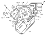
- FIG. 5 is an internal structural diagram showing the mechanical configuration of the lock mechanism of the first embodiment.
- the lock actuator 73 meshes with a connector 73a connected to an external power source and a controller (not shown), a motor 731 that rotates based on a command signal, a worm 732 that rotates together with a rotor of the motor 731, and a worm 732.
- a rotating worm wheel 734 a diameter smaller than that of the worm wheel 734 and having the same rotation shaft as the worm wheel 734, a drive gear 734a rotating relative to the worm wheel 734, and a tooth surface on the outer periphery meshing with the drive gear 734a And a driven member 735.
- Engaging convex portions 7341 that are partially raised are provided on the surface of the worm wheel 734, and an engaged portion 734a1 extending in a substantially fan shape is formed on the outer diameter of the drive gear 734a.
- the engaging convex portion 7341 also rotates.
- the drive gear 734a does not rotate in a state where the engagement convex portion 7341 and the engaged portion 734a1 are not engaged.
- the driving gear 734a starts rotating. This operation is the same whether the worm wheel 734 rotates clockwise or counterclockwise in FIG.
- the swing arm 71 is rotated by the torque of the motor 731 to the near side from the position where the swing arm 71 is locked or unlocked, and thereafter, that is, the position where the swing arm 71 is locked or unlocked.
- the swing arm 71 is rotated by the torque of the toggle spring 100.
- the driven member 735 is further rotated by the torque of the toggle spring 100.
- the engaging projection 7341 of the worm wheel 734 that operates integrally with the motor 731 rotates in a direction in which the engaged portion 734a1 that operates integrally with the driven member 735 moves away. Does not affect this rotation. With this configuration, even if the motor 731 has an abnormality and cannot be rotated, it can be easily rotated when the swing arm 71 is rotated and released manually. It can be done. The relationship with the toggle spring 100 will be described later.
- the driven member 735 has a substantially fan-shaped engagement portion 735a having a tooth surface formed on the outer periphery, and a rotation shaft portion 735b assembled to be integrated with the swing arm 71.
- the swing arm 71 is a member that operates using the rotation shaft portion 735b as a rotation shaft. In other words, the swing arm 71 is in a direction different from the insertion / removal direction of the charging connector 2 and is different from the rotation axis direction of the engagement member 23. Has a pivot axis.
- the lock actuator 73 is also used in an automatic door lock mechanism of a general vehicle, and the manufacturing cost can be reduced by diverting these parts as they are.
- FIG. 6 is a bottom view showing the configuration of the swing arm of the lock mechanism of the first embodiment.
- the swing arm 71 includes an attachment portion 710 attached so as not to rotate relative to the rotation shaft portion 735b of the lock actuator 73, and a cylindrical cylindrical wall 713 covering the outer periphery of the attachment portion 710.
- Three concave portions 712 are formed on the circumference of the attachment portion 710, and the convex portion formed on the rotating shaft portion 735b side is fitted into the concave portion 712, thereby restricting relative movement in the rotational direction.
- a through hole 711 is formed at the center of the attachment portion 710, and a fixing screw 72 for fixing the swing arm 71 and the rotation shaft portion 735 integrally therethrough.
- the through-hole 711 makes the upper part of the swing arm 71 and the lock actuator 73 side communicate with each other, the operation of the swing arm 71 becomes difficult due to freezing or the like. It also functions as a flow passage through which hot water circulates to quickly improve the frozen state.
- the fixing screw 72 is screwed by a female screw portion provided on the rotating shaft portion 735 side, whereby the rotating shaft portion 735 and the swing arm 71 are integrally operated.
- the fastening direction of the fixing screw 72 is set to be the same as the direction in which the swing arm 71 rotates in the unlocking direction. That is, even if a failure or the like occurs in the lock actuator 73 and the release operation cannot be performed at all, the swing arm 71 can be rotated in the release direction by tightening the fixing screw 72. Because.
- FIG. 7 is a schematic perspective view in a state where the charging connector and the charging port of the first embodiment are connected.
- the fixing screw 72 is provided in the forcible operation opening 74a at the time of failure and so as to be exposed in the bonnet hood.
- the hood hood release lever in the passenger compartment is usually operated. If the release lever can be operated, the position can be easily accessed. In other words, the position cannot be accessed even if the charging lid 32 is opened. Therefore, it is devised so that others who cannot access the passenger compartment cannot operate it without permission. Moreover, since it can be easily operated by a plus driver or the like equipped on the in-vehicle tool or the like, it can be released by the operator.
- a plate-like arm member 71d extends from the cylindrical wall 713 on the left side in FIG.
- the arm member 71d is designed to expand in a fan shape at the tip and overlap the claw portion 23d in a top view (corresponding to being positioned in the engaging member separation direction).
- the arm member 71d is formed with a lightening portion 71d1 for reducing the weight and a rib 714 for ensuring a required strength.
- the swing arm 71 is formed of resin and has an asymmetric shape in the top view as shown in FIG.
- the rotation center of the swing arm 71 (the center of the swing arm 71 in the thickness direction coincides with the rotation axis) and the rotation center of the engagement member 23 in the locked state (the width direction of the engagement member 23).
- An axis 01 that is a line connecting the center of the axis and a point that coincides with the rotation axis) is a reference line in the top view, and a symmetrical virtual line that is symmetrical in the vertical direction is drawn with a dotted line, and explanation is based on the relationship with this symmetrical virtual line To do.
- the portion above the axis 01 is a region where the swing arm 71 escapes when shifting from the restricted state by the lock mechanism to the unrestricted state. Therefore, the area above the axis 01 is defined as the escape area and the area below is defined as the passing area.
- the swing arm 71 is symmetrical in the escape area and the passage area, there are many areas located on the escape area side of the claw portion 23d. In this case, there are the following problems. That is, since the position of the charging port 4 is provided at a relatively low position of the vehicle, it is assumed that when another vehicle travels nearby, sherbet-like snow, muddy water, etc. is wound up and scattered into the charging port 4. Is done. Further, when charging is performed in a cryogenic environment, it is assumed that the scattered sherbet-like snow and muddy water are frozen, and a slab-like obstacle is formed using the arm member 71d of the swing arm 71 as a roof.
- the arm member 71d is largely scraped from the symmetrical virtual line to the vicinity of the claw portion 23d.
- the area 71d3 existing in the escape region of the arm member 71d (restricted with reference to a line connecting the rotation center of the swing arm 71 and the rotation center of the claw 23d when positioned in the separation direction of the claw 23d) Is the area 71d2 (the center of rotation when the claw portion 23d is in the separating direction) and the center of rotation of the claw portion 23d.
- the surface area of the upper surface in the direction of rotation to an unrestricted state is determined to be smaller.
- the roof portion in the escape area can be made small, and it is difficult to form icicle-like obstacles, so that the swing arm 71 can be smoothly operated when unlocking.
- the roof portion in the escape area can be made small, and it is difficult to form icicle-like obstacles, so that the swing arm 71 can be smoothly operated when unlocking.
- by scraping to the limit of the area overlapping with the claw portion 23d in a top view it is possible to reduce the possibility that an obstacle or the like is further formed while reliably restricting the movement of the claw portion 23d in the separation direction.
- the shape is symmetrical with the axis line 01 as the reference line. That is, when the swing arm 71 is rotated by the operation of the lock actuator 73, assuming that the swing arm 71 does not sufficiently rotate due to a failure or the like, the length of the outermost diameter portion 71f is secured more reliably. This is because the swing arm 71 can be positioned in the separation direction of 23d.
- FIG. 8 is a perspective view of the charging connector and the charging port according to the first embodiment in a connected state.
- the charging connector 2 is inserted into the charging port 4, the lock mechanism 7 is operated, and the swing arm 71 is positioned in the separation direction of the claw portion 23d, so that the claw portion 23d cannot move in the separation direction even if the release button 23a is pressed. . Accordingly, the engagement between the convex portion 41a and the claw portion 23d cannot be released, and the charging connector 2 is prohibited from being extracted.
- the charging port 4 of the vehicle is provided with a cover member 9 for protecting entry of dust and the like into the lock mechanism 7 and the like.
- the cover member 9 has an opening 91 that covers the lock mechanism 7 from the insertion / removal direction side of the charging connector 2 and into which the claw portion 23d can be inserted and a part of the swing arm 71 is exposed.
- the outermost diameter portion 71f of the swing arm 71 is exposed. If the gap between the cover member 9 and the outermost diameter portion 71f is large, it is possible to forcibly open the swing arm 71 by inserting a finger or the like into the gap. Therefore, the gap between the swing arm 71 and the cover member 9 is set narrow so as not to contact.
- the rotation direction length of the outermost diameter part 71f is set longer than the opening width (length in the rotation direction) of the opening 91.
- the distance between the inner peripheral surface of the cover member 9 and the locus of the outermost diameter portion 71 f when the swing arm 71 rotates is set to increase as the distance from the opening 91 increases. ing. That is, when the charging connector 2 is connected to the charging port 4 with dust or the like (gum, mud, lump of dust, etc.) attached to the claw portion 23d, the swing arm 71 rotates to It will work while scraping (sweeping) garbage.
- dust or the like gum, mud, lump of dust, etc.
- FIG. 9 is a schematic cross-sectional view showing the positional relationship between the engaging member and the swing arm according to the first embodiment.
- a predetermined gap a1 is provided between the upper surface of the swing arm 71 and the support extending portion 74b, and a predetermined gap b1 is also provided between the lower surface of the swing arm 71 and the claw portion 23d. Therefore, since the swing arm 71 does not come into contact with the support extending portion 74b and the claw portion 23d when the swing arm 71 rotates, the swing arm 71 can be operated smoothly.
- FIG. 10 is a schematic cross-sectional view showing the positional relationship between the engaging member and the swing arm when the engaging member of Example 1 is forcibly operated in the separating direction.
- the support extending portion 74b is provided, further deformation is suppressed by contact with the support extending portion 74b.
- even the resin swing arm 71 can ensure a sufficient strength against the compressive force. That is, the swing axis of the swing arm 71 has a rotation axis that is different from the insertion / removal direction of the charging connector 2 and that is different from the rotation axis direction of the engagement member 23.
- the rotation axis direction of the swing arm 71 and the rotation axis direction of the engaging member 23 are not in a parallel relationship, and the swing arm 71 is interposed and limited in the separating direction of the claw portion 23d, and The support extending portion 74b is provided. Therefore, even if an unreasonable force is input from the claw portion 23d, the swing arm 71 does not act in the turning direction, so that it is not necessary to make the swing arm 71 robust in the turning direction. Sufficient restricted state can be maintained without having to make the structure near the shaft robust.
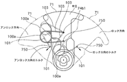
- FIG. 11 is a schematic explanatory diagram of a portion provided with the toggle spring of the first embodiment
- FIG. 12 is a schematic diagram showing mechanical operation of the toggle spring of the first embodiment
- FIG. 13 is a torque of the toggle spring and motor of the first embodiment.
- the horizontal axis represents the rotational position of the swing arm 71, and represents the position in the locked state (hereinafter referred to as the locked position), the position in the unlocked state (hereinafter referred to as the unlocked position), and the center position thereof.
- the vertical axis represents the torque acting on the swing arm 71.
- the upper part of the vertical axis represents the toggle spring torque acting in the locking direction
- the lower part of the vertical axis represents the toggle spring torque acting in the unlocking direction.
- the toggle spring 100 includes a coil portion 100a that generates elastic force, a swing arm side foot portion 101 that extends from the coil portion 100a and engages with the swing arm 71, and a swing arm side foot portion 101.
- the insertion portion 102 is bent in a substantially right angle direction and is rotatably inserted into an engagement hole 750 formed in the swing arm 71.
- the toggle spring 71 extends from the coil portion 100a and engages with the support extension portion 74b, and the vehicle body side foot portion 103 bends in a substantially right angle direction to form a support extension portion 74b.
- An insertion portion 104 is rotatably inserted into the formed engagement hole 74b1.
- FIG. 11 is a schematic view of the swing arm 71 viewed from the lateral direction in the neutral position, and the corresponding top surface configuration is a view shown in the neutral position portion of FIG.
- the toggle spring 100 is in a bent state.
- the toggle spring 100 tries to push and spread the respective foot portions 101 and 103, but the force acts in the radial direction with respect to the rotation center of the swing arm 71 and rotates the swing arm 71. Does not affect the direction. From this state, when the swing arm 71 is rotated in the locking direction by the motor 731, the coil portion 100 a is displaced downward in FIG. 12.
- the force that pushes and spreads the feet 101 and 103 of the toggle spring 100 has a rotational component in the locking direction of the swing arm 71, and the swing arm 71 is directed to the locked position by this torque. Is energized.
- the swing arm 71 is rotated in the unlocking direction by the motor 731, the coil portion 100a is displaced upward in FIG.
- the force that pushes and spreads the respective foot portions 101 and 103 of the toggle spring 100 has a rotational component in the unlocking direction of the swing arm 71, and the swing arm 71 is unlocked by this torque. It is energized towards.
- the toggle spring 100 moves in the gap between the swing arm 71 and the support extending portion 74b.
- the toggle spring 100 has a position where the insertion portion 74b1 and the insertion portion 750 are aligned with the swing arm rotation center (hereinafter referred to as a spring center position).
- a predetermined dead zone is generated in both directions around the center. In other words, if the toggle spring 100 does not rotate to some extent from when it is in the spring center position, it is not possible to generate a rotational torque that overcomes the friction.
- the motor 731 operates the swing arm 71 to the near side that reaches the lock position or the unlock position.
- the range in which the motor torque is output is a range from the unlock position to the predetermined lock region (hereinafter referred to as a first region) for the region acting in the lock direction.
- the region acting in the unlocking direction is a range from the lock position to the predetermined unlocking region beyond the center (hereinafter referred to as a second region).
- the swing arm 71 since there is a dead zone in the toggle spring 100, if the operation of the motor 731 is stopped within this dead zone, the swing arm 71 cannot move due to the toggle spring force. Therefore, when operating the motor 731, the motor 731 is always driven to exceed the dead zone of the toggle spring 100. In other words, the motor 731 is controlled so that the first region and the second region overlap.
- the dead zone of the toggle spring 100 is formed at a position overlapping the overlapping region. Thereby, the swing arm 71 can be moved to the lock position or the unlock position by the torque of the toggle spring 100.
- the dead zone is set in a region offset from the center position of the swing arm 71 toward the lock side.
- the dead zone is formed at a position that overlaps more in the region existing on the lock side from the neutral position than in the region existing on the unlock side from the neutral position.
- a specific dead zone offset method will be described.
- the insertion portion 74b1 and the insertion portion 750 have been described as the spring center position aligned with the swing arm rotation center in the neutral position.
- the reason for securing the unlocked state will be described. Basically, when the vehicle is stopped, no vibration or the like is input, and the swing arm 71 is not affected. Therefore, when the vehicle is in a stopped state such as during charging, the locked state is maintained. That is not difficult. On the other hand, since vibration or the like is input during traveling, if resonance frequency vibration of the swing arm 71 is input, the swing arm 71 may move to the locked state even though the swing arm 71 is unlocked. . Then, when the operator stops the vehicle at the charging stand and tries to charge it, the swing arm 71 is in the locked state, so the charging connector 2 cannot be inserted. Since the operator does not particularly operate the lock mechanism, such a situation is uncomfortable. Therefore, even if vibration or the like is input during traveling, the operator can avoid an uncomfortable feeling by ensuring the unlocked state.
- the swing arm 71 is located at a position beyond the motor torque range in the unlocking direction and closer to the unlocking position, and the toggle spring force cannot sufficiently act. think of.
- the motor torque cannot be applied, so the position cannot be changed and the charging connector 2 cannot be inserted. Therefore, in Example 1, before the claw portion 23d and the convex portion 41a are engaged, torque is applied in the one-end locking direction, and the torque is applied again in the unlocking direction.
- the initial position adjustment process for achieving the unlocked state is performed by eliminating the influence of the position shift and dust.
- FIG. 14 is a flowchart illustrating the initial position adjustment process according to the first embodiment.
- This control process is performed in a controller (not shown), and a control signal is output to the lock mechanism 7.
- step S10 it is determined whether or not a command (open) for opening the charging lid 32 is output. If open is output, the charging connector 2 is connected to the charging port 4, and the claw portion 23d and the convex portion 41a are connected. Therefore, before the engagement, the process proceeds to step S11 to execute the lock operation and the unlock operation to adjust the initial position of the swing arm 71.
- the claw portion 23d and the convex portion 41a are not engaged with each other, this control flow ends.
- the swing arm 71 is located at a position beyond the motor torque range in the unlocking direction and on the near side of the unlock position, which is an obstacle to insertion of the charging connector 2.
- the swing arm 71 can be returned to the proper initial position as the unlocking position.
- Example 1 has the following effects. (1) It has a convex portion 41a (engaged portion) that engages with the claw portion 23d (engagement portion) of the charging connector 2 by a user's operation, and power is supplied from an external power source in the engaged state.
- the charging port 4 the claw portion 23d, and the convex portion 41a are in the engaged state, the release operation of the claw portion 23d is restricted by the movement of the swing arm 71 (restricting member) in the locking direction.
- Lock mechanism 7 that achieves a locked state that restricts the release of the state and an unlocked state that allows the release operation by moving the swing arm 71 in the unlocking direction opposite to the locking direction, and locks the swing arm 71
- a controller (locking state control means) for moving the motor 731 to the nearer side than the predetermined position when moving to a predetermined position that achieves the state or unlocked state, and the claw portion 2 Before d and the convex portion 41a is engaged, with moving the swing arm 71 in the locking direction, a step S11 to be further moved in the unlocking direction (initial position adjusting means), a.
- the swing arm 71 can be returned to the proper initial position as the unlock position.
- a toggle spring 100 is provided between the swing arm 71 and the vehicle body side, and is moved from the near side to a predetermined position by the elastic force of the toggle spring 100. Therefore, since the entire operating range of the swing arm 71 is not operated by the motor, the swing arm 71 can avoid an excessive load from acting on the motor and the like, and can improve durability. Moreover, since it is moved by the toggle spring 100, an urging force can be applied to a predetermined position, and the predetermined position can be stably maintained.
- the lock mechanism 7 includes a first region where the torque of the motor 731 acts when the swing arm 71 is operated in the locked state, and a second region where the torque of the motor 731 acts when operated in the unlocked state.
- the motor 731 is controlled so as to overlap with the area, and a dead zone where the swing arm 71 does not operate due to the spring force of the toggle spring 100 is formed at a position overlapping the overlapping area. Therefore, the swing arm 71 can be moved to the lock position or the unlock position by the torque of the toggle spring 100.
- the dead zone is formed at a position that overlaps more in the region existing on the lock state side from the neutral position than in the region existing on the unlock state side from the neutral position. Therefore, even when vibration or the like is input during traveling, the unlocked state can be reliably ensured, and an uncomfortable feeling of the operator can be avoided.
- the limiting member is a swing arm that switches between a locked state and an unlocked state by turning. Therefore, it is possible to achieve a sufficiently restricted state while having a simple configuration. In addition, the manufacturing cost can be reduced by diverting the parts used in the existing automatic door lock mechanism and the like as they are.
- the present invention has been described based on each embodiment, but other configurations may be used.
- the charging port is provided in front of the vehicle.
- the charging port may be provided in the rear of the vehicle or in the side of the vehicle.
- the electric vehicle has been described in the embodiment, a plug-in hybrid vehicle or the like may be used.
- the configuration using the coil spring as the toggle spring is shown as an example.
- other configurations can be applied without any problem as long as the same effect is exhibited.
- a method of applying an urging force such as a seesaw type toggle switch may be used.
- the example of switching between the state restricted by the rotation and the state not restricted as the lock mechanism has been described. It does not matter.
- the initial position adjustment of the swing arm 71 is started using the open command of the charging lid 32 as a trigger.
- the initial position adjustment of the swing arm 71 may be started using another signal as a trigger.
- the initial position based on the recognition Adjustment may be started.
- the initial position adjustment may be started at a stage before the claw portion 23d and the convex portion 41a are engaged.
Landscapes
- Engineering & Computer Science (AREA)
- Computer Security & Cryptography (AREA)
- Power Engineering (AREA)
- Transportation (AREA)
- Mechanical Engineering (AREA)
- Electric Propulsion And Braking For Vehicles (AREA)
- Details Of Connecting Devices For Male And Female Coupling (AREA)
Abstract
L'invention porte sur un dispositif de commande de port de charge pour un véhicule électrique, avec lequel dispositif un état verrouillé qui restreint une opération de libération d'un état réuni pour une partie de réunion (23d) d'un connecteur de charge (2) et d'une partie réunie (41a) d'un port de charge (4) et un état déverrouillé qui permet celle-ci sont obtenus par l'actionnement d'un élément de restriction (71). A ce moment, l'élément de restriction (71) est déplacé vers un côté avant des positions prescrites qui produisent l'état verrouillé ou l'état déverrouillé par l'entraînement de puissance d'un moteur (731). De plus, avant que la partie de réunion (23d) et la partie réunie (41a) ne soient réunies, l'élément de restriction (71) est déplacé dans une direction de verrouillage, et est de plus déplacé dans la direction de déverrouillage.
Priority Applications (3)
| Application Number | Priority Date | Filing Date | Title |
|---|---|---|---|
| US14/374,704 US9178313B2 (en) | 2012-03-09 | 2013-02-21 | Electric vehicle charging port control device |
| CN201380012651.6A CN104160563B (zh) | 2012-03-09 | 2013-02-21 | 电动车辆的充电端口控制装置 |
| EP13757492.7A EP2824774B1 (fr) | 2012-03-09 | 2013-02-21 | Dispositif de commande de port de charge pour véhicule électrique |
Applications Claiming Priority (2)
| Application Number | Priority Date | Filing Date | Title |
|---|---|---|---|
| JP2012053813A JP5895618B2 (ja) | 2012-03-09 | 2012-03-09 | 電動車両の充電ポート制御装置 |
| JP2012-053813 | 2012-03-09 |
Publications (1)
| Publication Number | Publication Date |
|---|---|
| WO2013133037A1 true WO2013133037A1 (fr) | 2013-09-12 |
Family
ID=49116520
Family Applications (1)
| Application Number | Title | Priority Date | Filing Date |
|---|---|---|---|
| PCT/JP2013/054357 Ceased WO2013133037A1 (fr) | 2012-03-09 | 2013-02-21 | Dispositif de commande de port de charge pour véhicule électrique |
Country Status (5)
| Country | Link |
|---|---|
| US (1) | US9178313B2 (fr) |
| EP (1) | EP2824774B1 (fr) |
| JP (1) | JP5895618B2 (fr) |
| CN (1) | CN104160563B (fr) |
| WO (1) | WO2013133037A1 (fr) |
Families Citing this family (24)
| Publication number | Priority date | Publication date | Assignee | Title |
|---|---|---|---|---|
| JP5970767B2 (ja) * | 2011-09-27 | 2016-08-17 | 日産自動車株式会社 | 充電装置 |
| JP5648751B2 (ja) * | 2011-10-11 | 2015-01-07 | 日産自動車株式会社 | 充電ポートロック装置 |
| US9178312B2 (en) * | 2011-10-13 | 2015-11-03 | Nissan Motor Co., Ltd. | Charging port locking device |
| WO2013054646A1 (fr) * | 2011-10-13 | 2013-04-18 | 日産自動車株式会社 | Dispositif de verrouillage de port de charge |
| EP2768106B1 (fr) * | 2011-10-13 | 2019-11-20 | Nissan Motor Co., Ltd. | Dispositif de verrouillage de port de charge |
| JP5798935B2 (ja) * | 2012-01-17 | 2015-10-21 | 矢崎総業株式会社 | 電気コネクタ |
| JP5935388B2 (ja) * | 2012-02-29 | 2016-06-15 | 日産自動車株式会社 | 車両の充電ケーブル接続時における移動制限装置 |
| EP2871723B1 (fr) * | 2012-07-05 | 2018-04-25 | Nissan Motor Co., Ltd | Dispositif de port de charge destiné à un véhicule électrique |
| CN104412465A (zh) * | 2012-07-09 | 2015-03-11 | 日产自动车株式会社 | 电动车辆的充电端口装置 |
| JP5939927B2 (ja) * | 2012-08-06 | 2016-06-22 | 矢崎総業株式会社 | 充電コネクタ |
| WO2014157196A1 (fr) * | 2013-03-28 | 2014-10-02 | 矢崎総業株式会社 | Connecteur de charge |
| US9214757B2 (en) * | 2013-12-13 | 2015-12-15 | Denso Corporation | Contamination avoidance combination high voltage interlock cover |
| WO2016077690A1 (fr) | 2014-11-14 | 2016-05-19 | Henderson Ricky Jay | Système de port d'accueil d'alimentation |
| DE102017123208A1 (de) * | 2017-10-06 | 2019-04-11 | Kiekert Ag | Elektrische Anschlussvorrichtung für Elektro- oder Hybridkraftfahrzeuge |
| WO2019073851A1 (fr) | 2017-10-10 | 2019-04-18 | 株式会社 村上開明堂 | Dispositif actionneur de verrouillage d'orifice pour entrée de véhicule |
| CN108045254B (zh) * | 2017-12-19 | 2023-09-26 | 库卡机器人(广东)有限公司 | 用于无人搬运车的充电装置及具有其的无人搬运车 |
| CN108749637B (zh) * | 2018-07-19 | 2023-05-19 | 重庆工业职业技术学院 | 一种用于电动汽车的停车位及其使用方法 |
| CN111098723B (zh) * | 2018-10-26 | 2022-11-25 | 上海汽车集团股份有限公司 | 一种充电口电子锁控制方法和系统 |
| JP6705521B1 (ja) * | 2019-02-25 | 2020-06-03 | スズキ株式会社 | 電動車両 |
| CN110562084B (zh) * | 2019-09-10 | 2023-09-12 | 国创移动能源创新中心(江苏)有限公司 | 一种伸缩摆臂式充电机构运动控制系统及方法 |
| US11654786B2 (en) * | 2020-10-19 | 2023-05-23 | GM Global Technology Operations LLC | Charging port cooling with phase changing material and porous heat conductor cage |
| US11623538B1 (en) * | 2021-10-05 | 2023-04-11 | Mod.Al Group, Inc. | Ejector for electric vehicle charging connectors |
| EP4191803A1 (fr) * | 2021-12-03 | 2023-06-07 | Neutrik AG | Elément de déverrouillage et connecteur électrique l'utilisant |
| US11884170B1 (en) * | 2022-11-10 | 2024-01-30 | Evject, Inc. | Adapter for electric vehicle charging connectors |
Citations (2)
| Publication number | Priority date | Publication date | Assignee | Title |
|---|---|---|---|---|
| JP2010264847A (ja) | 2009-05-14 | 2010-11-25 | Toyota Motor Corp | 電動車両 |
| JP2011238530A (ja) * | 2010-05-12 | 2011-11-24 | Tokai Rika Co Ltd | 給電プラグロック装置 |
Family Cites Families (13)
| Publication number | Priority date | Publication date | Assignee | Title |
|---|---|---|---|---|
| FR2947393B1 (fr) | 2009-06-30 | 2011-07-29 | Valeo Securite Habitacle | Connecteur d'alimentation pour la recharge d'un vehicule electrique |
| JP5486397B2 (ja) * | 2010-05-12 | 2014-05-07 | 株式会社東海理化電機製作所 | 給電プラグロック装置 |
| JP5411059B2 (ja) * | 2010-05-18 | 2014-02-12 | 株式会社東海理化電機製作所 | 充電インレット装置 |
| JP5443270B2 (ja) * | 2010-05-27 | 2014-03-19 | 株式会社東海理化電機製作所 | プラグロック装置 |
| JP5524725B2 (ja) * | 2010-06-08 | 2014-06-18 | 株式会社東海理化電機製作所 | 給電プラグのロック装置 |
| US8075329B1 (en) * | 2010-06-08 | 2011-12-13 | Ford Global Technologies, Llc | Method and system for preventing disengagement between an electrical plug and a charge port on an electric vehicle |
| JP2012080646A (ja) * | 2010-09-30 | 2012-04-19 | Tokai Rika Co Ltd | 給電プラグロック装置 |
| JP5970767B2 (ja) * | 2011-09-27 | 2016-08-17 | 日産自動車株式会社 | 充電装置 |
| JP5648751B2 (ja) * | 2011-10-11 | 2015-01-07 | 日産自動車株式会社 | 充電ポートロック装置 |
| EP2768106B1 (fr) * | 2011-10-13 | 2019-11-20 | Nissan Motor Co., Ltd. | Dispositif de verrouillage de port de charge |
| WO2013054646A1 (fr) * | 2011-10-13 | 2013-04-18 | 日産自動車株式会社 | Dispositif de verrouillage de port de charge |
| US9178312B2 (en) * | 2011-10-13 | 2015-11-03 | Nissan Motor Co., Ltd. | Charging port locking device |
| JP5982897B2 (ja) * | 2012-03-14 | 2016-08-31 | 日産自動車株式会社 | 電動車両の充電ポート制御装置 |
-
2012
- 2012-03-09 JP JP2012053813A patent/JP5895618B2/ja active Active
-
2013
- 2013-02-21 CN CN201380012651.6A patent/CN104160563B/zh active Active
- 2013-02-21 US US14/374,704 patent/US9178313B2/en active Active
- 2013-02-21 EP EP13757492.7A patent/EP2824774B1/fr active Active
- 2013-02-21 WO PCT/JP2013/054357 patent/WO2013133037A1/fr not_active Ceased
Patent Citations (2)
| Publication number | Priority date | Publication date | Assignee | Title |
|---|---|---|---|---|
| JP2010264847A (ja) | 2009-05-14 | 2010-11-25 | Toyota Motor Corp | 電動車両 |
| JP2011238530A (ja) * | 2010-05-12 | 2011-11-24 | Tokai Rika Co Ltd | 給電プラグロック装置 |
Also Published As
| Publication number | Publication date |
|---|---|
| EP2824774B1 (fr) | 2019-10-30 |
| JP5895618B2 (ja) | 2016-03-30 |
| US9178313B2 (en) | 2015-11-03 |
| EP2824774A1 (fr) | 2015-01-14 |
| EP2824774A4 (fr) | 2015-09-23 |
| CN104160563B (zh) | 2016-08-17 |
| JP2013187160A (ja) | 2013-09-19 |
| CN104160563A (zh) | 2014-11-19 |
| US20150037994A1 (en) | 2015-02-05 |
Similar Documents
| Publication | Publication Date | Title |
|---|---|---|
| JP5895618B2 (ja) | 電動車両の充電ポート制御装置 | |
| JP6014724B2 (ja) | 電動車両の充電ポート装置 | |
| JPWO2014010337A1 (ja) | 電動車両の充電ポート装置 | |
| JP5970767B2 (ja) | 充電装置 | |
| JP5648751B2 (ja) | 充電ポートロック装置 | |
| JP5725196B2 (ja) | 充電ポートロック装置 | |
| JP5648753B2 (ja) | 充電ポートロック装置 | |
| JP5648752B2 (ja) | 充電ポートロック装置 | |
| JP5803542B2 (ja) | 充電装置 | |
| JP5966771B2 (ja) | 電動車両の充電ポート制御装置 | |
| JP5811757B2 (ja) | 充電装置 | |
| JP5805591B2 (ja) | 電動車両の充電ポート装置 | |
| JP2013255316A (ja) | 電動車両の充電ポート制御装置 |
Legal Events
| Date | Code | Title | Description |
|---|---|---|---|
| 121 | Ep: the epo has been informed by wipo that ep was designated in this application |
Ref document number: 13757492 Country of ref document: EP Kind code of ref document: A1 |
|
| WWE | Wipo information: entry into national phase |
Ref document number: 14374704 Country of ref document: US |
|
| WWE | Wipo information: entry into national phase |
Ref document number: 2013757492 Country of ref document: EP |
|
| NENP | Non-entry into the national phase |
Ref country code: DE |