WO2013136423A1 - Tête de travail et dispositif de retrait de bande supérieure - Google Patents
Tête de travail et dispositif de retrait de bande supérieure Download PDFInfo
- Publication number
- WO2013136423A1 WO2013136423A1 PCT/JP2012/056341 JP2012056341W WO2013136423A1 WO 2013136423 A1 WO2013136423 A1 WO 2013136423A1 JP 2012056341 W JP2012056341 W JP 2012056341W WO 2013136423 A1 WO2013136423 A1 WO 2013136423A1
- Authority
- WO
- WIPO (PCT)
- Prior art keywords
- tape
- head
- pair
- top tape
- roller
- Prior art date
- Legal status (The legal status is an assumption and is not a legal conclusion. Google has not performed a legal analysis and makes no representation as to the accuracy of the status listed.)
- Ceased
Links
Images






Classifications
-
- H—ELECTRICITY
- H05—ELECTRIC TECHNIQUES NOT OTHERWISE PROVIDED FOR
- H05K—PRINTED CIRCUITS; CASINGS OR CONSTRUCTIONAL DETAILS OF ELECTRIC APPARATUS; MANUFACTURE OF ASSEMBLAGES OF ELECTRICAL COMPONENTS
- H05K13/00—Apparatus or processes specially adapted for manufacturing or adjusting assemblages of electric components
- H05K13/04—Mounting of components, e.g. of leadless components
- H05K13/0417—Feeding with belts or tapes
Definitions
- the present invention relates to a work head capable of executing a work of peeling a top tape from a taped component, and a top tape peeling device including the work head.
- the taped component is a tape-like component in which an electronic circuit component (hereinafter may be abbreviated as “electronic component”) is accommodated in a large number of accommodating recesses formed in the carrier tape, and the tape is wound in a wound state. It is held by the feeder.
- the tape feeder is structured to supply electronic components at a predetermined position by sending out the taped components, and the taped components held by the tape feeder can be exchanged to cope with the shortage of electronic components, etc. Has been.
- the replacement work of the taped parts is a relatively time-consuming work, and the time required for the operator to perform the replacement work of the taped parts is relatively long. For this reason, in recent years, as described in Patent Document 1 below, development of an on-board working apparatus that can automatically replace a taped part instead of manually is being promoted.
- the working head according to claim 1 of the present application is a working head that is moved to an arbitrary position on the base by the moving device and performs the work at the arbitrary position, and is a tape.
- a delivery device that feeds out the top tape held by a top tape holding mechanism, and performs an operation of peeling the top tape from the taped component.
- the working head according to claim 2 is the working head according to claim 1, wherein the top tape clamping mechanism includes a pair of head-side rollers, and the pair of head-side rollers is a mutual roller.
- the top tape is clamped by a surface.
- At least one of the pair of head-side rollers is open to at least one of the roller surfaces and can supply negative pressure. It has a suction port communicating with the passage.
- the working head according to the second or third aspect, wherein one of the pair of head-side rollers is configured to be able to approach and separate from the other, the top.
- the tape clamping mechanism includes a roller moving mechanism that moves one of the pair of head-side rollers so as to approach or separate from the other.
- the working head according to any one of the second to fourth aspects, wherein the feeding device rotates one of the pair of head-side rollers. It is characterized by having.
- the top tape peeling apparatus of Claim 6 is a working head as described in any one of Claim 1 thru
- the top tape peeling device according to claim 7 is the top tape peeling device according to claim 6, wherein the storage is sandwiched between the pair of head-side rollers and sent out by the delivery device. It has a pair of storage side rollers for sandwiching the top tape, and stores the top tape by rotation of the pair of storage side rollers.
- the top tape is clamped by the top tape clamping mechanism, and the clamped top tape can be sent out by the delivery device.
- the top tape can be suitably peeled from the taped component.
- the work head can be moved to an arbitrary position on the base by the moving device. For this reason, it becomes possible to move the top tape peeled off from the taped part to an arbitrary position, for example, a storage for discarding the top tape, and the execution of the peeling work can be performed automatically and reliably. It becomes possible.
- the top tape is sandwiched between the roller surfaces of the pair of rollers.
- the top tape can be suitably sandwiched, and the top tape can be sent out suitably.
- a suction port is formed on the roller surface. Accordingly, the top tape can be adsorbed on the roller surface before the top tape is sandwiched between the roller surfaces of the pair of rollers. That is, the top tape can be held between the roller surfaces of a pair of rollers by rotating the roller with the top tape adsorbed on the roller surface. Therefore, according to the work head of the third aspect, the top tape can be properly clamped.
- one of the pair of rollers can be brought close to or separated from the other by the roller moving mechanism.
- the pair of rollers is separated, and when the top tape is positioned between the pair of rollers in a separated state.
- the top tape can be easily held by the pair of rollers.
- the top tape can be easily detached by separating the pair of rollers in a state where the top tape is sandwiched. Thereby, for example, it becomes possible to easily dispose of the top tape.
- one of the pair of rollers is rotated by an electromagnetic motor.
- the top tape held by the pair of rollers can be suitably fed out.
- the work head holding the top tape is moved by the moving device to a storage for discarding the top tape. Thereby, it is possible to automatically perform the operation of discarding the top tape in the storage.
- the storage has a pair of rollers, and the pair of rollers can sandwich the top tape fed from the work head. ing.
- the top tape enters the storage by driving the pair of rollers. This makes it possible to reliably discard the top tape in the storage.
- FIG. 1 shows an electronic component mounting apparatus (hereinafter sometimes abbreviated as “mounting apparatus”) 10.
- the figure is a perspective view in which a part of the exterior component of the mounting apparatus 10 has been removed.
- the mounting apparatus 10 includes one system base 12 and two electronic component mounting machines (hereinafter, may be abbreviated as “mounting machines”) 16 arranged side by side adjacent to each other on the system base 12. In other words, the electronic component is mounted on the circuit board.
- the direction in which the mounting machines 16 are arranged is referred to as an X-axis direction
- a horizontal direction perpendicular to the direction is referred to as a Y-axis direction.
- Each of the mounting machines 16 included in the mounting apparatus 10 mainly includes a mounting machine main body 24 configured to include a frame unit 20 and a beam unit 22 overlaid on the frame unit 20, and a circuit board in the X-axis direction.
- a transport device 26 that transports and fixes the work board 28 at a set position, a work head 28 that performs work on the circuit board fixed by the transport device 26, and the like.
- a moving device 30 that moves in the Y-axis direction and an electronic component supply device 32 (hereinafter sometimes abbreviated as “supply device”) that is disposed in front of the frame portion 20 and supplies electronic components. .
- the transport device 26 includes two conveyor devices 40 and 42, and the two conveyor devices 40 and 42 are parallel to each other and extend in the X-axis direction so that the central portion in the Y-axis direction of the frame portion 20. It is arranged.
- Each of the two conveyor devices 40 and 42 conveys the circuit board supported by each conveyor device 40 and 42 in the X-axis direction by an electromagnetic motor (not shown) and holds the circuit board fixedly at a predetermined position. It is supposed to be a structure.
- the moving device 30 is an XY robot type moving device, and an electromagnetic motor (not shown) that slides a slider 46 that holds the work head 28 in the X-axis direction, and an electromagnetic motor (not shown) that slides in the Y-axis direction.
- the working head 28 can be moved to an arbitrary position on the frame portion 20 by the operation of these two electromagnetic motors.
- the supply device 32 is disposed at an end portion on the front side of the frame portion 20 and is a feeder-type supply device.
- the supply device 32 accommodates a taped part 70 (see FIG. 2) in which electronic parts are taped and accommodated in a state in which the taped part 70 is wound around a reel 72, and is accommodated in each of the plurality of tape feeders 74. And a plurality of delivery devices (not shown) for feeding out the taped parts 70, and the electronic parts are sequentially supplied from the taped parts 70 at the supply position.
- the taped component 70 includes a carrier tape 82 in which a large number of receiving recesses 78 and feed holes 80 are formed at an equal pitch, an electronic component 84 received in the receiving recess 78, and a carrier tape 82.
- the top cover tape 86 covers the housing recess 78 in which the electronic component 84 is housed.
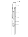
- the tape feeder 74 has a reel holding portion 88 for holding a reel 72 around which the taped component 70 is wound, and a taped component 70 drawn out from the reel 72 on the upper end surface. It is composed of a feeder main body 90 that is extended.
- a sprocket 92 that engages with a feed hole 80 formed in the carrier tape 82 of the taped component 70 is built in the feeder main body 90, and the carrier tape 82 is rotated by the sprocket 92 being rotated by the delivery device.
- the taped component 70 with the top cover tape 86 attached thereto is sent out in the direction away from the reel 72 on the upper end surface of the feeder main body 90.
- the top cover tape 86 is peeled from the carrier tape 82, so that the accommodation recesses 78 in which the electronic components 84 are accommodated are sequentially released at the supply position located at the tip of the upper end surface of the feeder main body 90.
- the tape feeder 74 includes a spare reel holder 98 for holding the spare reel 72, and the spare reel holder 98 is provided in the frame unit 20.
- the spare reel holding unit mounting base 100 is detachable. Specifically, the spare reel holding part mounting base 100 is provided with a connector connecting part 102, and a connector 104 is provided at the upper end of the side wall surface of the spare reel holding part 98 on the feeder main body 90 side. Then, by attaching / detaching the connector 104 to / from the connector connecting portion 102, the spare reel holding portion 98 is attached to / detached from the spare reel holding portion mounting base 100.
- 3 shows the tape feeder 74 with the connector 104 removed from the connector connecting portion 102.
- FIGS. 4 and 5 show the tape with the connector 104 connected to the connector connecting portion 102.
- FIG. A feeder 74 is shown.
- the casing 106 of the spare reel holding unit 98 has an open upper end and a lower end, and a spare reel 72 extends from the upper end of the casing 106.
- the upper end portion of the reel 72 held by the reel holding portion 88 enters the lower end portion of the casing 106 in a state where the connector 104 is connected to the connector connecting portion 102.
- the upper end and the lower end of the casing 108 of the reel holding unit 88 are also opened, and the connector 104 is connected to the inside of the casing 108 of the reel holding unit 88 and the inside of the casing 106 of the spare reel holding unit 98. In the state where it is connected to the connection part 102, it communicates.
- a first reel stopper 110 is provided inside the casing 108 of the reel holding portion 88 to prevent the reel 72 from dropping off from the opened lower end portion.
- the first reel stopper 110 has a rod shape and is swingably held by the casing 108 at one end.
- the first reel stopper 110 is normally configured to maintain a predetermined angle, and by supporting the lower end portion of the reel 72 at the other end portion, the falling of the reel 72 from the lower end portion of the casing 108 is prevented. is doing. Then, by driving the stopper release mechanism 112, the first reel stopper 110 is swung so that the other end portion thereof is directed downward, whereby the reel 72 is moved to the lower end portion of the casing 108 of the reel holding portion 88. It comes to drop out from.
- a second reel stopper 114 for preventing the spare reel 72 from falling off from the opened lower end is also provided in the casing 106 of the spare reel holding portion 98.
- the second reel stopper 114 has substantially the same structure as the first reel stopper 110 and normally prevents the spare reel 72 from falling off from the lower end of the casing 106. Then, by driving the stopper release mechanism 116, the second reel stopper 114 is swung so that the other end portion thereof is directed downward, whereby the spare reel 72 is moved to the casing 106 of the spare reel holding portion 98. Drop off from the lower end of the. That is, the spare reel 72 accommodated in the spare reel holder 98 can be accommodated in the reel holder 88.
- the taped component 70 wound around the spare reel 72 accommodated in the casing 106 is sent out toward the feeder main body 90 of the tape feeder 74.
- a device 118 is provided. As shown in FIGS. 4 and 6, the delivery device 118 includes a pair of holding unit side rollers 120 and 122, and the taped component 70 is formed by the roller surfaces of the pair of holding unit side rollers 120 and 122. It is to be pinched.
- the width of the holding unit side roller 122 located above the pair of holding unit side rollers 120 and 122 is approximately the same as the width of the taped component 70.
- the width of the holding portion side roller 120 positioned below is narrower than the width of the holding portion side roller 122 as shown in FIG. For this reason, the part in which the feed hole 80 of the taped component 70 is formed is sandwiched between the roller surfaces of the pair of holding unit side rollers 120 and 122. Accordingly, the taped component 70 can be held between the roller surfaces of the pair of holding unit side rollers 120 and 122 without crushing the housing recess 78 of the taped component 70.
- the holding unit side roller 120 positioned below is rotatably held by the casing 106.
- the holding portion side roller 122 positioned above is rotatably held by the bracket 124, and the bracket 124 is held by the casing 106 so as to be movable in the vertical direction.
- the delivery device 118 includes a roller moving mechanism 126 that moves the bracket 124 in the vertical direction, and a roller rotating mechanism 128 that rotates the holding portion side roller 122 held by the bracket 124.
- the delivery device 118 can move the holding unit side roller 122 closer to and away from the holding unit side roller 120 by the roller moving mechanism 126, and the pair of holding unit side rollers 120, It is possible to switch between the state where the taped component 70 is held by 122 and the state where the holding is released. Then, the taped component 70 can be sent out toward the feeder main body 90 by driving the roller rotating mechanism 128 while the taped component 70 is sandwiched between the pair of holding unit side rollers 120 and 122. Has been.
- two detection sensors 130 and 132 are provided on the upper end surface of the feeder main body 90 where the taped component 70 is extended. Each of the detection sensors 130 and 132 can detect whether or not there is a taped component 70 above each of the detection sensors 130 and 132. As the taped component 70 is sent out, the taped component 70 is detected. 70 ends can be detected.
- the detection sensor 130 provided in the vicinity of the sprocket 92 detects the tip of the taped component 70, and the reel holding portion 88 of the feeder main body 90.
- the detection sensor 132 provided on the side detects the rear end portion of the taped component 70.
- the working head 28 has a head main body 140 that is attached to the slider 46 of the moving device 30, and an underside of the head main body 140 is used for holding and releasing electronic components.
- a suction nozzle 142 is attached.
- the suction nozzle 142 is connected to a negative pressure air and a positive pressure air passage connected to a positive / negative pressure supply device (not shown), and sucks and holds the electronic component at a negative pressure, so that a slight positive pressure is supplied.
- the structure is such that the electronic parts held in the above are detached.
- the suction nozzle 142 has a lifting device (not shown) that lifts and lowers the electronic component that is sucked and held, and a rotation device (not shown) that rotates the sucked and held electronic component around the axis of the suction nozzle 142, It is possible to change the vertical position of the electronic component to be held and the holding posture of the electronic component.
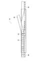
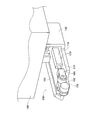
- the suction nozzle 142 can be attached to and detached from the head main body 140, and a tape peeling tool 150 can be attached to the head main body 140 as shown in FIGS. 3 to 5 instead of the suction nozzle 142.
- the tape peeling tool 150 is capable of holding the top cover tape 86 of the taped component 70 and sending the clamped top cover tape 86 upward, and peeling the top cover tape 86 from the taped component 70. It is possible.
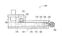
- the tape peeling tool 150 has a longitudinal peeling tool main body 152 and is mounted on the head main body 140 so that the longitudinal direction thereof is the horizontal direction. Specifically, a generally cylindrical mounting portion 154 is inserted into one end portion of the peeling tool main body 152 so as to extend in the vertical direction, and an upper end portion of the mounting portion 154 protrudes above the peeling tool main body 152. Yes. Then, the upper end portion of the protruding mounting portion 154 is fitted into a mounting hole (not shown) formed in the lower end surface of the head main body 140, so that the tape peeling tool 150 is mounted on the head main body 140.
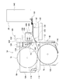
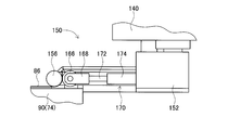
- a head-side first roller 156 is rotatably supported at the other end of the peeling tool main body 152, and a bevel gear 158 is attached to the shaft 157 of the head-side first roller 156.
- a bevel gear 162 fixed to the motor shaft of the stepping motor 160 is engaged with the bevel gear 158.
- the stepping motor 160 is configured to rotate every 90 degrees.
- the shaft portion 157 of the head-side first roller 156 has a cylindrical shape, and the shaft portion 157 is connected to the air passage 163.
- a positive / negative pressure supply device (not shown) is connected to the air passage 163 so that positive or negative pressure air can be supplied.
- An opening 164 is formed on the roller surface of the head-side first roller 156, and the opening 164 communicates with the inside of the shaft portion 157. As a result, air can be sucked or blown out from the opening 164 formed on the roller surface.
- FIG. 9 shows the tape stripper 150 from a viewpoint from below, and as shown in the figure, the rotation angle of the stepping motor 160 is determined so that the opening 164 faces directly below.
- a head-side second roller 166 is provided so as to face the head-side first roller 156.
- the head-side second roller 166 is rotatably supported by the bracket 168, and the bracket 168 is fixed to the tip of the piston rod 172 of the piston 170.
- the piston 170 is disposed on the peeling tool main body 152 so as to extend in the longitudinal direction, and the cylinder 174 of the piston 170 is fixed to the peeling tool main body 152.
- the head-side second roller 166 can be moved closer to and away from the head-side first roller 156 as the piston 170 expands and contracts, and the piston 170 is extended, whereby the head-side first roller 166 is extended.
- roller surface of the roller 156 and the roller surface of the head-side second roller 166 come into contact with each other and the piston 170 contracts, so that the roller surface of the head-side first roller 156 and the roller surface of the head-side second roller 166 are in contact with each other. It is supposed to leave.
- the tape peeling tool 150 is provided with an elevating mechanism 176 that raises and lowers the peeling tool main body 152 in the vertical direction.
- the lifting mechanism 176 includes a rack 178 fixed to the peeling tool main body 152, a pinion gear 180 meshing with the rack 178, and an electromagnetic motor 182 fixed to the mounting portion 154 and driving the pinion gear 180.
- the mounting portion 154 passes through one end portion of the peeling tool main body 152 in the vertical direction, and is movable in the vertical direction with respect to the peeling tool main body 152.
- the pinion gear 180 is rotated by the drive of the electromagnetic motor 182, and the rack 178 moves in the vertical direction, so that the peeling tool main body 152 moves in the vertical direction.
- the top cover of the taped component 70 is formed between the roller surface of the head side first roller 156 and the roller surface of the head side second roller 166 by extending the piston 170.
- the tape 86 can be clamped.
- the top cover tape 86 sandwiched between the two roller surfaces can be sent out. Thereby, as will be described in detail later, the top cover tape 86 can be peeled from the taped component 70.
- the mounting machine 16 includes a tape storage 186 for storing the top cover tape 86 peeled off from the taped component 70.
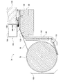
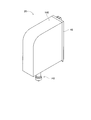
- the tape storage 186 is provided at the upper end of the feeder main body 90 of the tape feeder 74, and has a housing 188 in which the inside is hollow. An opening is formed in a part of the lower end surface of the housing 188, and a pair of storage-side rollers 190 and 192 are provided in the portion where the opening is formed.
- the pair of storage-side rollers 190 and 192 are arranged in a state where the roller surfaces are in contact with each other.
- An electromagnetic motor (not shown) is connected to one of the pair of storage-side rollers 190 and 192. When the electromagnetic motor is driven, one storage-side roller 190 rotates and the other rotation causes the other to rotate.
- the storage side roller 192 also rotates.
- the mounting machine 16 includes a mark camera (not shown) and a parts camera (see FIG. 1) 196.
- the mark camera is fixed to the lower surface of the slider 46 so as to face downward, and can be imaged at an arbitrary position on the frame unit 20 by being moved by the moving device 30.
- the parts camera 196 is provided between the transport device 26 of the frame unit 20 and the supply device 32 in a state of facing upward, and the suction nozzle 142 is mounted when the suction nozzle 142 is attached to the head body 140.
- Image data obtained by the mark camera and the part camera 196 is processed by an image processing apparatus (not shown), and various information is acquired.
- the mounting device 10 when the work head 28 is a mounting head, that is, when the suction nozzle 142 is mounted on the head main body 140, the electronic component is mounted on the circuit board with the above-described configuration. It is possible to perform mounting work. More specifically, first, the conveyor boards 40 and 42 convey the circuit board to the mounting work position, and the circuit board is fixedly held at that position. Next, the working head 28 is moved onto the circuit board by the moving device 30, and the circuit board is imaged by the mark camera. The type of the circuit board and the circuit board holding position error by the conveyor devices 40 and 42 are acquired by the imaging.
- the electronic component corresponding to the acquired type of circuit board is supplied by the tape feeder 74, and the working head 28 is moved by the moving device 30 to the supply position of the electronic component. Thereby, the electronic component is sucked and held by the suction nozzle 142 of the work head 28. Subsequently, the work head 28 holding the electronic component is moved onto the parts camera 196 by the moving device 30, and the electronic component held by the suction nozzle 142 is imaged by the parts camera 196. The holding position error of the electronic component is acquired by the imaging. Then, the moving device 30 moves the work head 28 to the mounting position on the circuit board and rotates the suction nozzle 142 based on the holding position error between the circuit board and the electronic component, and then the electronic component is mounted.
- the mounting device 10 is configured to suck and hold the electronic component supplied by the tape feeder 74 by the suction nozzle 142 of the work head 28 and mount the sucked and held electronic component on the circuit board.
- the taped component 70 accommodated in the tape feeder 74 that is, the reel 72 around which the taped component 70 is wound, is replaced in order to cope with a shortage of electronic components. It is possible.
- the reel replacement operation is performed manually, and the operator has to spend a relatively long time for the reel replacement operation.
- the mounting apparatus 10 can automatically perform a reel replacement operation.
- the automatic reel replacement operation in the mounting apparatus 10 will be described in detail.
- the taped component 70 is pulled out from the reel 72 accommodated in the reel holding unit 88.
- electronic components are supplied from the taped component 70.
- the rear end of the taped component 70 is detached from the reel 72 and pulled out to the upper end surface of the feeder main body 90.
- the rear end of the taped component 70 is detected by the detection sensor 132. That is, it is detected that the taped component 70 accommodated in the reel holding portion 88 is small.
- the taped component 70 sandwiched between the pair of holding unit side rollers 120 and 122 is sent out by the roller rotating mechanism 128. That is, the taped component 70 is sent out from the reel 72 accommodated in the spare reel holder 98 toward the upper end of the feeder main body 90 by the roller rotating mechanism 128.
- the leading end of the taped component 70 pulled out from the reel 72 accommodated in the spare reel holding portion 98 is the rear end of the taped component 70 pulled out from the reel 72 accommodated in the reel holding portion 88. It is sent out toward the sprocket 92 so as to follow the part.
- the tape feeder 74 is provided with a path for guiding the taped component 70 sent out by the roller rotating mechanism 128 to the sprocket 92.
- the reel 72 around which the taped component 70 is not wound is dropped from the lower end portion of the casing 108 of the reel holding portion 88.
- the stopper release mechanism 112 is driven, and the first reel stopper 110 is swung so that the end portion thereof is directed downward, whereby the reel 72 is moved to the casing 108 of the reel holding portion 88. Drop off from the bottom edge.
- the leading end portion of the taped component 70 drawn from the reel 72 accommodated in the spare reel holding portion 98 is sent out by the roller rotating mechanism 128 to the engagement position of the sprocket 92.
- the detection sensor 130 determines whether the tip of the taped component 70 has reached the engagement position. Specifically, when the tape sensor 70 is sent out a predetermined amount after the detection sensor 130 detects the tip of the tape component 70, the tip of the tape component 70 has reached the engagement position. To be judged.
- the lower end of the casing 106 of the spare reel holding unit 98 is used.
- the reel 72 around which the taped component 70 is wound is dropped. That is, the reel 72 around which the taped component 70 fed to the engagement position is wound is moved from the spare reel holding unit 98 to the reel holding unit 88.
- the stopper release mechanism 116 is driven, and the second reel stopper 114 is swung so that its end portion is directed downward, whereby the reel 72 is held from the spare reel holding portion 98 to the reel. Moved to section 88.
- the taped component 70 sandwiched between the pair of holding unit side rollers 120 and 122 is a pair of holding units.
- the side rollers 120 and 122 are separated from each other. Specifically, when the leading end portion of the taped component 70 is sent to the engagement position of the sprocket 92, the roller moving mechanism 126 moves the holding portion side roller 122 upward, and the pair of holding portion side rollers 120 and 122 are moved. The pinching by is released.
- the width of the holding unit side roller 120 positioned below the pair of holding unit side rollers 120 and 122 is narrower than the width of the taped component 70 as described above. For this reason, when the holding of the taped component 70 by the pair of holding unit side rollers 120 and 122 is released, the pair of holding unit side rollers 120 is removed along with the dropping of the reel 72 in the spare reel holding unit 98. , 122.
- the top cover tape 86 is peeled off by the work head 28 in which the tape peeling tool 150 is mounted on the head main body 140.
- the tip end portion of the taped component 70 wound around the reel 72 newly accommodated in the reel holding portion 88 is pulled out to the engagement position of the sprocket 92.
- a position slightly downstream of the engagement position is a supply position, and a peeling operation is performed at the supply position.
- the top cover tape 86 is formed at the tip of the taped component 70 wound around the reel 72 accommodated in the spare reel holding unit 98, that is, at the tip of the taped component 70 drawn to the supply position. It is slightly peeled off from the carrier tape 82 (in this embodiment, it is peeled off by about 5 mm). This is because the taped component 70 from which the top cover tape 86 has been slightly peeled off from the carrier tape 82 is wound around the reel 72 accommodated in the spare reel holder 98. That is, in the taped component 70 wound around the spare reel holding portion 88, the top cover tape 86 is slightly peeled off from the carrier tape 82 in advance by the operator.
- the working head 28 with the tape peeling tool 150 attached to the head main body 140 is moved by the moving device 30 at the supply position, that is, at the tip of the taped component 70. It is moved upward. Specifically, the head-side first roller 156 of the tape peeling tool 150 is moved above the front end portion of the top cover tape 86 slightly peeled off from the carrier tape 82. Then, the peeling tool main body 152 is moved downward by the lifting mechanism 176. At this time, negative pressure is supplied to the air passage 163 and air is sucked from the opening 164.
- the tip of the top cover tape 86 slightly peeled off from the carrier tape 82 is attracted to the roller surface of the head-side first roller 156.
- the roller surface of the head side first roller 156 and the roller surface of the head side second roller 166 are separated from each other. That is, the piston 170 is contracted.
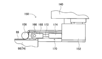
- the head-side first roller 156 When the tip of the top cover tape 86 is attracted to the roller surface of the head-side first roller 156, the head-side first roller 156 is rotated 90 degrees by driving the stepping motor 160. As a result, the tip of the top cover tape 86 is positioned between the roller surface of the head-side first roller 156 and the roller surface of the head-side second roller 166, as shown in FIG.
- the sprocket 92 is also rotated, and the taped component 70 is also sent out as the top cover tape 86 is peeled off from the carrier tape 82.
- the piston 170 is extended. As a result, as shown in FIG. 13, the top end portion of the top cover tape 86 is sandwiched between the head-side first roller 156 and the head-side second roller 166.
- the tape peeling tool 150 in a state of sandwiching the front end portion of the top cover tape 86 is moved below the tape storage 186 by the moving device 30.
- the tip of the top cover tape 86 sandwiched between the head side first roller 156 and the head side second roller 166 has a pair of storage side rollers 190 of the tape storage case 186 as shown in FIG. , 192
- the working head 28 is moved by the moving device 30.
- the top cover tape 86 is peeled from the carrier tape 82.
- the sprocket 92 is also rotated, and the taped component 70 is also sent out along with the peeling of the top cover tape 86 from the carrier tape 82.
- the top cover tape 86 sandwiched between the head side first roller 156 and the head side second roller 166 is sent out by driving of the stepping motor 160.
- positive pressure is supplied to the air passage 163, and air is blown out from the opening 164 on the roller surface of the head-side first roller 156.
- sticking of the top cover tape 86 to the roller surface of the head-side first roller 156 is prevented, and the top cover tape 86 can be appropriately fed upward.
- the electromagnetic motor connected to one of the pair of storage-side rollers 190 and 192 is also driven, and the pair of storage-side rollers 190 and 192 is also rotated.
- the top cover tape 86 fed upward from between the head side first roller 156 and the head side second roller 166 is sandwiched by the pair of storage side rollers 190 and 192 and is stored in a pair.
- the top cover tape 86 is stored in the tape storage 186 by the rotation of the storage side rollers 190 and 192.
- the driving of the stepping motor 160 is stopped, and as shown in FIG.
- the holding of the top cover tape 86 by the head side second roller 166 is released. That is, the piston 170 is contracted.
- the tape peeling tool 150 is moved to the tape storage. Evacuated from below 186.
- the work head 28 is once moved in the X-axis direction by the moving device 30 and then moved in the Y-axis direction. . Accordingly, the tape peeling tool 150 can be retracted from below the tape storage 186 without interfering with the top cover tape 86 held between the pair of storage-side rollers 190 and 192.
- the work head 28 When the tape peeling tool 150 is retracted from below the tape storage 186, the work head 28 is moved above the supply position by the moving device 30. At that position, the taped component 70 located at the supply position, specifically, the accommodation recess 78 of the carrier tape 82 from which the top cover tape 86 has been peeled off, is imaged by the mark camera. Whether or not the electronic component 84 is housed in the housing recess 78 is determined by the imaging. When it is determined that the electronic component 84 is housed in the housing recess 78, the reel replacement operation is terminated, and the mounting operation is resumed.
- the sprocket 92 is rotated and the taped component 70 is fed out by a predetermined pitch. Then, the accommodation recess 78 is imaged again, and the above determination is made. This determination is repeated until it is determined that the electronic component 84 is stored in the storage recess 78. Thereby, the taped component 70 can be sent out to a position where the electronic component can be supplied at the supply position.
- the replacement work of the reel 72 can be performed fully automatically only by mounting the spare reel holder 98 on the tape feeder 74.
- the top head tape 86 can be peeled off by the work head 28 in which the tape peeling tool 150 is mounted on the head main body 140, so that the troublesome peeling work can be preferably automated. It has become.
- the working head 28 in which the tape peeling tool 150 is attached to the head main body 140 is an example of the working head, and includes the working head 28, the moving device 30, and the tape storage 186.
- the head side roller 156 and the head side second roller 166, the stepping motor 160, and the piston 170 constituting the tape peeling tool 150 are examples of a top tape clamping mechanism (head side roller), a feeding device (electromagnetic motor), and a roller moving mechanism.
- the opening 164 formed on the roller surface of the head side roller 156 is an example of a suction port.
- the taped component 70 is an example of a taped component
- the housing recess 78, the carrier tape 82, and the top cover tape 86 that constitute the taped component 70 are examples of a housing recess, a carrier tape, and a top tape.
- the frame unit 20, the moving device 30, the tape feeder 74, and the tape storage 186 are examples of a base, a moving device, a tape feeder, and a storage, and the storage side rollers 190 and 192 that constitute the tape storage 186 are It is an example of a storage side roller.
- this invention is not limited to the said Example, It is possible to implement in the various aspect which gave various change and improvement based on the knowledge of those skilled in the art. Specifically, for example, in the above embodiment, the top cover tape 86 is sandwiched by a pair of rollers 156, 166, 190, 192, but the top cover tape 86 in a sandwiched state can be sent out. If it exists, it is possible to employ
- FIG. 20 Frame portion (base) 28: Working head (top tape peeling device) 30: Moving device (top tape peeling device) 70: Tape-made parts 74: Tape feeder 78: Housing recess 82: Carrier tape 86: Top cover tape 156 : Head side first roller (head side roller) (top tape clamping mechanism) 160: stepping motor (electromagnetic motor) (feeding device) 164: opening (suction port) 166: head side second roller (head side roller) (top (Tape clamping mechanism) 170: piston (roller moving mechanism) 186: tape storage (storage) 190: storage side roller 192: storage side roller
Landscapes
- Engineering & Computer Science (AREA)
- Manufacturing & Machinery (AREA)
- Microelectronics & Electronic Packaging (AREA)
- Supply And Installment Of Electrical Components (AREA)
Priority Applications (2)
| Application Number | Priority Date | Filing Date | Title |
|---|---|---|---|
| JP2014504497A JP5781686B2 (ja) | 2012-03-13 | 2012-03-13 | 作業ヘッド、および、トップテープ剥離装置 |
| PCT/JP2012/056341 WO2013136423A1 (fr) | 2012-03-13 | 2012-03-13 | Tête de travail et dispositif de retrait de bande supérieure |
Applications Claiming Priority (1)
| Application Number | Priority Date | Filing Date | Title |
|---|---|---|---|
| PCT/JP2012/056341 WO2013136423A1 (fr) | 2012-03-13 | 2012-03-13 | Tête de travail et dispositif de retrait de bande supérieure |
Publications (1)
| Publication Number | Publication Date |
|---|---|
| WO2013136423A1 true WO2013136423A1 (fr) | 2013-09-19 |
Family
ID=49160394
Family Applications (1)
| Application Number | Title | Priority Date | Filing Date |
|---|---|---|---|
| PCT/JP2012/056341 Ceased WO2013136423A1 (fr) | 2012-03-13 | 2012-03-13 | Tête de travail et dispositif de retrait de bande supérieure |
Country Status (2)
| Country | Link |
|---|---|
| JP (1) | JP5781686B2 (fr) |
| WO (1) | WO2013136423A1 (fr) |
Cited By (12)
| Publication number | Priority date | Publication date | Assignee | Title |
|---|---|---|---|---|
| WO2017042901A1 (fr) * | 2015-09-09 | 2017-03-16 | 富士機械製造株式会社 | Dispositif porte-bobine du type supplémentaire |
| WO2017208287A1 (fr) * | 2016-06-01 | 2017-12-07 | パナソニックIpマネジメント株式会社 | Système de montage de composants |
| JP2019176188A (ja) * | 2016-06-01 | 2019-10-10 | パナソニックIpマネジメント株式会社 | 部品実装システム |
| JP2020161666A (ja) * | 2019-03-27 | 2020-10-01 | パナソニックIpマネジメント株式会社 | リール支持装置および部品搭載装置 |
| CN112970340A (zh) * | 2018-11-13 | 2021-06-15 | 株式会社富士 | 作业机及电气元件保持方法 |
| JP2021119611A (ja) * | 2019-03-29 | 2021-08-12 | パナソニックIpマネジメント株式会社 | キャリアテープ保持装置、保持体およびキャリアテープパッケージ体 |
| JP2021132211A (ja) * | 2019-03-29 | 2021-09-09 | パナソニックIpマネジメント株式会社 | キャリアテープ保持装置、保持体およびキャリアテープパッケージ体 |
| JP2021145154A (ja) * | 2020-06-29 | 2021-09-24 | 株式会社Fuji | 追加形リール保持装置 |
| JP2022008322A (ja) * | 2017-08-21 | 2022-01-13 | パナソニックIpマネジメント株式会社 | 部品供給装置および部品供給装置におけるテープ剥離方法 |
| JP2022136223A (ja) * | 2017-08-21 | 2022-09-15 | パナソニックIpマネジメント株式会社 | 部品供給装置および部品供給方法 |
| JP2023054213A (ja) * | 2020-06-29 | 2023-04-13 | 株式会社Fuji | 部品実装機 |
| CN117433886A (zh) * | 2023-12-13 | 2024-01-23 | 苏州华兴源创科技股份有限公司 | 编带剥离力测试装置及编带剥离力测试方法 |
Citations (3)
| Publication number | Priority date | Publication date | Assignee | Title |
|---|---|---|---|---|
| JPH02165696A (ja) * | 1988-12-20 | 1990-06-26 | Hitachi Ltd | 電子部品供給装置および該装置用リールホルダセッティング方法 |
| JPH0417399A (ja) * | 1990-05-10 | 1992-01-22 | Nagata Seiki Co Ltd | 電子部品供給装置 |
| JP2005539370A (ja) * | 2002-05-24 | 2005-12-22 | デラウェア キャピタル フォーメーション インク | 自動装填式コンポーネントテープフィーダ |
-
2012
- 2012-03-13 JP JP2014504497A patent/JP5781686B2/ja not_active Expired - Fee Related
- 2012-03-13 WO PCT/JP2012/056341 patent/WO2013136423A1/fr not_active Ceased
Patent Citations (3)
| Publication number | Priority date | Publication date | Assignee | Title |
|---|---|---|---|---|
| JPH02165696A (ja) * | 1988-12-20 | 1990-06-26 | Hitachi Ltd | 電子部品供給装置および該装置用リールホルダセッティング方法 |
| JPH0417399A (ja) * | 1990-05-10 | 1992-01-22 | Nagata Seiki Co Ltd | 電子部品供給装置 |
| JP2005539370A (ja) * | 2002-05-24 | 2005-12-22 | デラウェア キャピタル フォーメーション インク | 自動装填式コンポーネントテープフィーダ |
Cited By (43)
| Publication number | Priority date | Publication date | Assignee | Title |
|---|---|---|---|---|
| US10918000B2 (en) | 2015-09-09 | 2021-02-09 | Fuji Corporation | Component supply device |
| CN107950083A (zh) * | 2015-09-09 | 2018-04-20 | 富士机械制造株式会社 | 追加型带盘保持装置 |
| JPWO2017042901A1 (ja) * | 2015-09-09 | 2018-06-28 | 株式会社Fuji | 追加形リール保持装置 |
| EP3349558A4 (fr) * | 2015-09-09 | 2018-07-18 | Fuji Machine Mfg. Co., Ltd. | Dispositif porte-bobine du type supplémentaire |
| CN107950083B (zh) * | 2015-09-09 | 2020-07-28 | 株式会社富士 | 追加型带盘保持装置 |
| WO2017042901A1 (fr) * | 2015-09-09 | 2017-03-16 | 富士機械製造株式会社 | Dispositif porte-bobine du type supplémentaire |
| WO2017208287A1 (fr) * | 2016-06-01 | 2017-12-07 | パナソニックIpマネジメント株式会社 | Système de montage de composants |
| JP2017216379A (ja) * | 2016-06-01 | 2017-12-07 | パナソニックIpマネジメント株式会社 | 部品実装システム |
| CN109156097A (zh) * | 2016-06-01 | 2019-01-04 | 松下知识产权经营株式会社 | 部件安装系统 |
| JP2019176188A (ja) * | 2016-06-01 | 2019-10-10 | パナソニックIpマネジメント株式会社 | 部品実装システム |
| US10477746B2 (en) | 2016-06-01 | 2019-11-12 | Panasonic Intellectual Property Management Co., Ltd. | Component mounting system |
| JP2023076620A (ja) * | 2017-08-21 | 2023-06-01 | パナソニックIpマネジメント株式会社 | 部品供給装置および部品供給装置におけるテープ剥離方法 |
| JP7515088B2 (ja) | 2017-08-21 | 2024-07-12 | パナソニックIpマネジメント株式会社 | 部品供給装置および部品供給装置におけるテープ剥離方法 |
| JP7390533B2 (ja) | 2017-08-21 | 2023-12-04 | パナソニックIpマネジメント株式会社 | 部品供給装置および部品供給方法 |
| JP2022136223A (ja) * | 2017-08-21 | 2022-09-15 | パナソニックIpマネジメント株式会社 | 部品供給装置および部品供給方法 |
| JP2022008322A (ja) * | 2017-08-21 | 2022-01-13 | パナソニックIpマネジメント株式会社 | 部品供給装置および部品供給装置におけるテープ剥離方法 |
| CN112970340A (zh) * | 2018-11-13 | 2021-06-15 | 株式会社富士 | 作业机及电气元件保持方法 |
| CN112970340B (zh) * | 2018-11-13 | 2022-12-27 | 株式会社富士 | 作业机及电气元件保持方法 |
| JP2020161666A (ja) * | 2019-03-27 | 2020-10-01 | パナソニックIpマネジメント株式会社 | リール支持装置および部品搭載装置 |
| JP7245975B2 (ja) | 2019-03-27 | 2023-03-27 | パナソニックIpマネジメント株式会社 | リール支持装置および部品搭載装置 |
| JP7281631B2 (ja) | 2019-03-29 | 2023-05-26 | パナソニックIpマネジメント株式会社 | キャリアテープ保持装置および部品搭載装置 |
| JP7386401B2 (ja) | 2019-03-29 | 2023-11-27 | パナソニックIpマネジメント株式会社 | 部品搭載装置 |
| CN114554827A (zh) * | 2019-03-29 | 2022-05-27 | 松下知识产权经营株式会社 | 部件搭载装置 |
| CN114641201A (zh) * | 2019-03-29 | 2022-06-17 | 松下知识产权经营株式会社 | 载带保持装置以及部件搭载装置 |
| US12466681B2 (en) | 2019-03-29 | 2025-11-11 | Panasonic Intellectual Property Management Co., Ltd. | Carrier tape holding device, holder, and carrier tape package body |
| JP7186348B2 (ja) | 2019-03-29 | 2022-12-09 | パナソニックIpマネジメント株式会社 | 部品搭載装置 |
| JP2021119611A (ja) * | 2019-03-29 | 2021-08-12 | パナソニックIpマネジメント株式会社 | キャリアテープ保持装置、保持体およびキャリアテープパッケージ体 |
| US12006175B2 (en) | 2019-03-29 | 2024-06-11 | Panasonic Intellectual Property Management Co., Ltd. | Carrier tape holding device, holder, and carrier tape package body |
| JP2021132211A (ja) * | 2019-03-29 | 2021-09-09 | パナソニックIpマネジメント株式会社 | キャリアテープ保持装置、保持体およびキャリアテープパッケージ体 |
| JP7266167B2 (ja) | 2019-03-29 | 2023-04-28 | パナソニックIpマネジメント株式会社 | 部品搭載装置 |
| JP2021141329A (ja) * | 2019-03-29 | 2021-09-16 | パナソニックIpマネジメント株式会社 | キャリアテープ保持装置、保持体およびキャリアテープパッケージ体 |
| JP2021132210A (ja) * | 2019-03-29 | 2021-09-09 | パナソニックIpマネジメント株式会社 | キャリアテープ保持装置、保持体およびキャリアテープパッケージ体 |
| CN114531839B (zh) * | 2019-03-29 | 2023-09-29 | 松下知识产权经营株式会社 | 部件搭载装置 |
| CN114554827B (zh) * | 2019-03-29 | 2023-09-29 | 松下知识产权经营株式会社 | 部件搭载装置 |
| CN114641201B (zh) * | 2019-03-29 | 2023-09-29 | 松下知识产权经营株式会社 | 载带保持装置以及部件搭载装置 |
| CN114531839A (zh) * | 2019-03-29 | 2022-05-24 | 松下知识产权经营株式会社 | 部件搭载装置 |
| JP7369315B2 (ja) | 2020-06-29 | 2023-10-25 | 株式会社Fuji | 部品実装機 |
| JP2023054213A (ja) * | 2020-06-29 | 2023-04-13 | 株式会社Fuji | 部品実装機 |
| JP2021145154A (ja) * | 2020-06-29 | 2021-09-24 | 株式会社Fuji | 追加形リール保持装置 |
| JP2022003710A (ja) * | 2020-06-29 | 2022-01-11 | 株式会社Fuji | 追加形リール保持装置 |
| JP7035262B2 (ja) | 2020-06-29 | 2022-03-14 | 株式会社Fuji | 追加形リール保持装置 |
| CN117433886A (zh) * | 2023-12-13 | 2024-01-23 | 苏州华兴源创科技股份有限公司 | 编带剥离力测试装置及编带剥离力测试方法 |
| CN117433886B (zh) * | 2023-12-13 | 2024-03-22 | 苏州华兴源创科技股份有限公司 | 编带剥离力测试装置及编带剥离力测试方法 |
Also Published As
| Publication number | Publication date |
|---|---|
| JP5781686B2 (ja) | 2015-09-24 |
| JPWO2013136423A1 (ja) | 2015-08-03 |
Similar Documents
| Publication | Publication Date | Title |
|---|---|---|
| JP5781686B2 (ja) | 作業ヘッド、および、トップテープ剥離装置 | |
| CN101784181B (zh) | 电子组件供给器及具有该电子组件供给器的芯片安装器 | |
| CN107114009B (zh) | 电子元件供给装置、卷盘装置、带处理装置以及元件收纳带的补充方法 | |
| CN105532082B (zh) | 对基板作业系统、作业方法及供料器转移方法 | |
| US11564341B2 (en) | Reel holding device arranged in component mounting machine and robot system including reel holding device | |
| CN106686967B (zh) | 部件供给装置以及部件供给方法 | |
| JP5746593B2 (ja) | 電子部品供給装置 | |
| CN104704938B (zh) | 对基板作业机 | |
| JP6916390B2 (ja) | フィーダおよび部品実装機 | |
| CN110857194A (zh) | 卷轴支架、带供给装置、机械手、机器人以及部件安装系统 | |
| CN107950085A (zh) | 另置式带盘保持装置 | |
| JP6545677B2 (ja) | テープフィーダ | |
| JP2022168137A (ja) | 部品実装装置 | |
| JP6412125B2 (ja) | 部品装着機 | |
| EP3007534B1 (fr) | Système pour monter des composants de circuit électronique | |
| CN103857270A (zh) | 电子元件的安装方法以及表面安装机 | |
| WO2016038668A1 (fr) | Dispositif de support de dispositif d'alimentation de bande | |
| JPWO2017098628A1 (ja) | リール保持装置 | |
| JP7260343B2 (ja) | パーツフィーダ | |
| JP2010157623A (ja) | 電子部品装着装置及び電子部品装着方法 | |
| KR100942164B1 (ko) | 부품 실장기용 캐리어 테이프 자동공급장치 | |
| JP6346068B2 (ja) | 部品供給装置、表面実装機、及び部品の供給方法 | |
| JP5192453B2 (ja) | 電子部品装着装置 | |
| KR20130088657A (ko) | 부품 실장기용 캐리어 테이프 자동공급 장치 | |
| JP5305762B2 (ja) | 電子部品実装方法、および電子部品実装装置 |
Legal Events
| Date | Code | Title | Description |
|---|---|---|---|
| 121 | Ep: the epo has been informed by wipo that ep was designated in this application |
Ref document number: 12870976 Country of ref document: EP Kind code of ref document: A1 |
|
| ENP | Entry into the national phase |
Ref document number: 2014504497 Country of ref document: JP Kind code of ref document: A |
|
| NENP | Non-entry into the national phase |
Ref country code: DE |
|
| 122 | Ep: pct application non-entry in european phase |
Ref document number: 12870976 Country of ref document: EP Kind code of ref document: A1 |