WO2013136785A1 - Procédé de fabrication de coulée, dispositif de fabrication associé et coulée - Google Patents
Procédé de fabrication de coulée, dispositif de fabrication associé et coulée Download PDFInfo
- Publication number
- WO2013136785A1 WO2013136785A1 PCT/JP2013/001642 JP2013001642W WO2013136785A1 WO 2013136785 A1 WO2013136785 A1 WO 2013136785A1 JP 2013001642 W JP2013001642 W JP 2013001642W WO 2013136785 A1 WO2013136785 A1 WO 2013136785A1
- Authority
- WO
- WIPO (PCT)
- Prior art keywords
- molten metal
- outer contour
- casting
- defining members
- bath
- Prior art date
- Legal status (The legal status is an assumption and is not a legal conclusion. Google has not performed a legal analysis and makes no representation as to the accuracy of the status listed.)
- Ceased
Links
Images





Classifications
-
- B—PERFORMING OPERATIONS; TRANSPORTING
- B22—CASTING; POWDER METALLURGY
- B22D—CASTING OF METALS; CASTING OF OTHER SUBSTANCES BY THE SAME PROCESSES OR DEVICES
- B22D11/00—Continuous casting of metals, i.e. casting in indefinite lengths
- B22D11/14—Plants for continuous casting
- B22D11/145—Plants for continuous casting for upward casting
-
- B—PERFORMING OPERATIONS; TRANSPORTING
- B22—CASTING; POWDER METALLURGY
- B22D—CASTING OF METALS; CASTING OF OTHER SUBSTANCES BY THE SAME PROCESSES OR DEVICES
- B22D11/00—Continuous casting of metals, i.e. casting in indefinite lengths
- B22D11/04—Continuous casting of metals, i.e. casting in indefinite lengths into open-ended moulds
- B22D11/041—Continuous casting of metals, i.e. casting in indefinite lengths into open-ended moulds for vertical casting
-
- B—PERFORMING OPERATIONS; TRANSPORTING
- B22—CASTING; POWDER METALLURGY
- B22D—CASTING OF METALS; CASTING OF OTHER SUBSTANCES BY THE SAME PROCESSES OR DEVICES
- B22D11/00—Continuous casting of metals, i.e. casting in indefinite lengths
- B22D11/006—Continuous casting of metals, i.e. casting in indefinite lengths of tubes
-
- B—PERFORMING OPERATIONS; TRANSPORTING
- B22—CASTING; POWDER METALLURGY
- B22D—CASTING OF METALS; CASTING OF OTHER SUBSTANCES BY THE SAME PROCESSES OR DEVICES
- B22D11/00—Continuous casting of metals, i.e. casting in indefinite lengths
- B22D11/12—Accessories for subsequent treating or working cast stock in situ
- B22D11/124—Accessories for subsequent treating or working cast stock in situ for cooling
Definitions
- the present invention relates to a manufacturing method of a casting, a manufacturing device thereof, and a casting, and particularly, to a manufacturing method of a casting that uses a free casting method, a manufacturing device thereof, and a casting that is manufactured using the free casting method.
- a metallic product having a complex form is manufactured by filling melted metal (molten metal) into a mold having a cavity having a predetermined form and solidifying the molten metal in the mold.
- a casting defect such as solidification cracking, shrinkage cavity or porosity, for example, may occur because of restriction and solidification due to cooling from the inner wall surface of the cavity of the mold.
- Patent Literatures 1 to 3 are methods of drawing out molten metal from the bath surface of a molten metal bath storing melted metal (molten metal) along a predetermined path, solidifying the molten metal drawn out, and forming a casting.
- the methods are for forming a casting having a predetermined form by solidifying, by predetermined cooling means, the molten metal which has been drawn out from the bath surface and whose form is temporarily retained, newly drawing out melted metal from the bath surface by gradually separating the solidified molten metal from the bath surface, and continuously solidifying the drawn out molten metal.
- Patent Literature 1 there is a problem that the outer contour of a casting is defined by guide rollers, and castings that can be manufactured are limited to castings having simple forms, such as a tapered round bar.
- Patent Literatures 2 and 3 there is a problem that an outlet of molten metal is restricted by a form or a partition member provided above the bath surface of a molten metal bath, and the degree of freedom of the form of a casting to be manufactured is low.
- the present invention is made in view of the above problems, and has its object to provide a manufacturing method of a casting and a manufacturing device thereof which are capable of easily manufacturing a casting having a complex form and of increasing the degree of freedom of form of the casting to be manufactured, and a casting manufactured using the manufacturing method and the manufacturing device.
- a manufacturing method of a casting of the present invention is a manufacturing method of a casting including drawing out molten metal from a bath surface of a molten metal bath, solidifying the molten metal which has been drawn out and forming a casting, the manufacturing method including arranging an outer contour unit configured from a plurality of outer contour defining members for defining an outer contour of the casting in a region between the bath surface of the molten metal bath and a solid region where the molten metal is solidified and drawing out the molten metal drawn out from the bath surface through a region determined by the outer contour unit, and changing the outer contour of the casting by moving at least one of the plurality of outer contour defining members according to the drawing out of the molten metal.
- examples of the forming material of the molten metal adopted by the manufacturing method described above include metal such as iron, aluminum, magnesium, titanium and the like, and an alloy thereof.
- molten includes, in addition to a complete liquid phase state, a solid-liquid state where a liquid phase and a solid phase are mixed.
- the outer contour of molten metal which has been drawn out from the bath surface of the molten metal bath and which is in a soft state before solidification can be freely changed by a simple method of arranging an outer contour unit configured from a plurality of outer contour defining members for defining the outer contour of a casting in a region between the bath surface of the molten metal bath and a solid region where the molten metal is solidified, and moving at least one of the plurality of outer contour defining members according to the drawing out of the molten metal at the time of drawing out the molten metal drawn out from the bath surface through a region determined by the outer contour unit.
- the outer contour of the molten metal in a soft state can be desirably changed while drawing out the molten metal from the bath surface of the molten metal bath, a casting having a complex form can be easily manufactured and the degree of freedom of form of a casting to be manufactured can be increased.
- an inner contour unit configured from a plurality of inner contour defining members for defining, on an inner side of the outer contour unit, an inner contour of the casting is preferably arranged in the region between the bath surface of the molten metal bath and the solid region where the molten metal is solidified and the molten metal drawn out from the bath surface is preferably drawn out through a region determined by the outer contour unit and the inner contour unit, and the inner contour of the casting is preferably changed by moving at least one of the plurality of inner contour defining members according to the drawing out of the molten metal.
- the outer contour and the inner contour of molten metal which has been drawn out from the bath surface of the molten metal bath and which is in a soft state before solidification can be changed by a simple method of arranging, in a region between the bath surface of the molten metal bath and a solid region where the molten metal is solidified, an outer contour unit configured from a plurality of outer contour defining members for defining the outer contour of the casting and an inner contour unit configured from a plurality of inner contour defining members for defining, on the inner side of the outer contour unit, the inner contour of the casting, and moving, at the time of drawing out the molten metal which has been drawn out from the bath surface through a region determined by the outer contour unit and the inner contour unit, at least one of the plurality of outer contour defining members and at least one of the plurality of inner contour defining members according to the drawing out of the molten metal.
- the form of the molten metal in a soft state can be desirably changed while drawing out the molten metal from the bath surface of the molten metal bath, and thus, the degree of freedom of form of a casting to be manufactured can be drastically increased.
- adjacent outer contour defining members, of the plurality of outer contour defining members may be arranged being separated from each other, or adjacent inner contour defining members, of the plurality of inner contour defining members, may be arranged being separated from each other.
- movement regions can be secured for the plurality of outer contour defining members constituting the outer contour unit and the plurality of inner contour defining members constituting the inner contour unit, the plurality of outer contour defining members and the plurality of inner contour defining members can be freely moved according to the drawing out of molten metal, and the degree of freedom of form of a casting to be manufactured can be even more increased. Additionally, also when adjacent outer contour defining members or adjacent inner contour defining members are arranged being separated from each other, the form of molten metal between the members is temporarily retained by an oxide film formed on the surface or surface tension.
- a manufacturing device of a casting of the present invention includes a molten metal bath for storing molten metal, cooling means for solidifying the molten metal drawn out from a bath surface of the molten metal bath, an outer contour unit that is configured from a plurality of outer contour defining members for defining an outer contour of a casting, the outer contour unit being arranged in a region between the bath surface of the molten metal bath and a solid region where the molten metal is solidified by the cooling means, and moving means for moving at least one of the plurality of outer contour defining members according to the drawing out of the molten metal.
- examples of the cooling means adopted by the manufacturing device described above include means for directly cooling the molten metal drawn out from the bath surface using a coolant or the like, means for indirect cooling via an induction body, made of metal, used for drawing out molten metal or an already solidified portion of the molten metal, and a plurality of cooling means may be used in combination.
- examples of coolant used by the cooling means described above include a gas such as air or inert gas, and a liquid such as water.
- an outer contour unit configured from a plurality of outer contour defining members for defining the outer contour of a casting is arranged in a region between the bath surface of a molten metal bath and a solid region where the molten metal is solidified by the cooling means, and at least one of the plurality of outer contour defining members can be moved using moving means, and since the outer contour of molten metal in a soft state can be desirably changed by moving at least one of the plurality of outer contour defining members while drawing out the molten metal from the bath surface of the molten metal bath, a casting having a complex form can be easily manufactured, and the degree of freedom of form of a casting to be manufactured can be increased.
- an inner contour unit that is configured from a plurality of inner contour defining members for defining an inner contour of the casting, the inner contour unit being arranged on an inner side of the outer contour unit and in a region between the bath surface of the molten metal bath and the solid region where the molten metal is solidified by the cooling means, and moving means for moving at least one of the plurality of inner contour defining members according to the drawing out of the molten metal.
- an outer contour unit configured from a plurality of outer contour defining members for defining the outer contour of a casting and an inner contour unit configured from a plurality of inner contour defining members for defining, on the inner side of the outer contour unit, the inner contour of the casting are arranged in a region between the bath surface of a molten metal bath and a solid region where the molten metal is solidified by the cooling means, and at least one of the plurality of outer contour defining members and the plurality of inner contour defining members can be moved using moving means, and since the form of molten metal in a soft state can be desirably changed by moving at least one of the plurality of outer contour defining members and the plurality of inner contour defining members while drawing out the molten metal from the bath surface of the molten metal bath, the degree of freedom of form of a casting to be manufactured can be drastically increased.
- adjacent outer contour defining members, of the plurality of outer contour defining members may be arranged being separated from each other, or adjacent inner contour defining members, of the plurality of inner contour defining members, may be arranged being separated from each other.
- At least the plurality of outer contour defining members or the plurality of inner contour defining members may be in line contact with the molten metal that is drawn out through a region determined by the outer contour unit and the inner contour unit, or at least the plurality of outer contour defining members or the plurality of inner contour defining members may be in surface contact with the molten metal that is drawn out through a region determined by the outer contour unit and the inner contour unit.
- the outer contour defining members and the inner contour defining members constituting the outer contour unit and the inner contour unit can be miniaturized, and the frame of the whole manufacturing device can be miniaturized by reducing the driving torque of the moving means or the like, for example.
- the molten metal that is drawn out through the region determined by the outer contour unit and the inner contour unit can be supported by a larger area, and the accuracy of form of a casting to be manufactured can be even more increased.
- a casting of the present invention is a casting that is formed by molten metal being drawn out from a bath surface of a molten metal bath and the molten metal which has been drawn out being solidified, where an outer contour unit configured from a plurality of outer contour defining members for defining an outer contour of the casting is arranged in a region between the bath surface of the molten metal bath and a solid region where the molten metal is solidified, and where the casting is formed by the outer contour being changed by at least one of the plurality of outer contour defining members being moved according to the drawing out of the molten metal at a time of the molten metal drawn out from the bath surface being drawn out through a region determined by the outer contour unit.
- the solid structure is directed in one direction by the molten metal drawn out from the bath surface of the molten metal bath being continuously solidified, and the quality can be effectively improved in spite of the complex form.
- an inner contour unit configured from a plurality of inner contour defining members for defining, on an inner side of the outer contour unit, an inner contour of the casting is preferably arranged in the region between the bath surface of the molten metal bath and the solid region where the molten metal is solidified, and the casting is preferably formed by the inner contour being changed by at least one of the plurality of inner contour defining members being moved according to the drawing out of the molten metal at a time of the molten metal drawn out from the bath surface being drawn out through a region determined by the outer contour unit and the inner contour unit.
- the outer contour and the inner contour of the molten metal are changed according to the drawing out of the molten metal, resulting in a casting having an even more complex form.
- the degree of freedom of design of a casting can be effectively increased by a simple method, and productivity can be increased with respect to castings having complex forms.
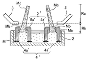
- Fig. 1 is a vertical cross-sectional view describing a manufacturing method of a casting of the present invention, and (a) is a view describing a state immediately after drawing out of molten metal from a molten metal bath and (b) is a view describing a state where a part of the molten metal drawn out from the molten metal bath is solidified.
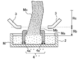
- Fig. 2 is a vertical cross-sectional view describing another embodiment of the manufacturing method of a casting shown in Fig. 1.
- Fig. 3 is a vertical cross-sectional view describing still another embodiment of the manufacturing method of a casting shown in Fig. 1.
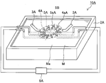
- Fig. 4 is a perspective view showing an embodiment 1 of a manufacturing device of a casting of the present invention.
- Fig. 1 is a vertical cross-sectional view describing a manufacturing method of a casting of the present invention.
- FIG. 5 is a view describing a state immediately after drawing out of molten metal from a molten metal bath using the manufacturing device shown in Fig. 4, and (a) is a vertical cross-sectional view thereof and (b) is an arrow view along line A1-A1 in Fig. 5(a).
- Fig. 6 is a view describing a state where a part of molten metal drawn out from a molten metal bath using the manufacturing device shown in Fig. 4 is solidified, and (a) is a vertical cross-sectional view thereof and (b) is an arrow view along line B1-B1 in Fig. 6(a).
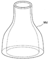
- Fig. 7 is a perspective view showing an embodiment 1 of a casting manufactured by the manufacturing device shown in Fig. 4.
- Fig. 8 is a perspective view showing an embodiment 2 of the manufacturing device of a casting of the present invention.
- Fig. 9 is a view describing a state immediately after drawing out of molten metal from a molten metal bath using the manufacturing device shown in Fig. 8, and (a) is a vertical cross-sectional view thereof and (b) is an arrow view along line A2-A2 in Fig. 9(a).
- Fig. 10 is a view describing a state where a part of molten metal drawn out from a molten metal bath using the manufacturing device shown in Fig. 8 is solidified, and (a) is a vertical cross-sectional view thereof and (b) is an arrow view along line B2-B2 in Fig. 10(a).
- Fig. 11 is a perspective view showing an embodiment 2 of a casting manufactured by the manufacturing device shown in Fig. 8.
- Fig. 1 is a vertical cross-sectional view describing a manufacturing method of a casting of the present invention
- Fig. 1(a) is a view describing a state immediately after drawing out of molten metal from a molten metal bath
- Fig. 1(b) is a view describing a state where a part of the molten metal drawn out from the molten metal bath is solidified.
- the manufacturing method of a casting of the present embodiment mainly includes a drawing process of drawing out molten metal from a molten metal bath, and a forming process of solidifying and forming the molten metal drawn out from the molten metal bath, and the drawing process and the forming process are performed as one process in the case casting is to be continuously performed.
- an induction body 1 having a basic form for example, a tubular form having a circular cross section, a polygonal cross section or the like
- a basic form for example, a tubular form having a circular cross section, a polygonal cross section or the like
- the induction body 1 is separated from a bath surface Ma of the molten metal M in the molten metal bath 2, to thereby draw out the molten metal M from the bath surface Ma of the molten metal bath 2.
- the ambient atmosphere of the molten metal M drawn out from the bath surface Ma of the molten metal bath 2 is air atmosphere or oxidizing atmosphere
- an oxide film is formed on the surface of the molten metal M, which has been drawn out
- the ambient atmosphere of the molten metal M is a nitrogen atmosphere
- a nitride film is formed on the surface of the molten metal M, which has been drawn out.
- the atmosphere is other than the air atmosphere, the oxidizing atmosphere or the nitrogen atmosphere where no surface film is formed, surface tension acts on the surface of the molten metal M, which has been drawn out.
- the form of the surface of the molten metal M drawn out from the bath surface Ma of the molten metal bath 2 is temporarily retained by the oxide film, a nitride film, surface tension or the like, and molten metal Mb in a soft state (a semi-solid state) whose form is retained (hereinafter, referred to as "retained molten metal") is formed between the bath surface Ma of the molten metal bath 2 and the induction body 1.
- the molten metal M is continuously drawn out from the bath surface Ma of the molten metal bath 2 by the retained molten metal Mb gradually separating from the bath surface Ma of the molten metal bath 2 following the movement of the induction body 1 and the molten metal M being drawn out from the bath surface Ma of the molten metal bath 2 following the retained molten metal Mb in a semi-solid state.
- an outer contour unit 4 configured from a plurality of outer contour defining members 4a for defining the outer contour of a casting to be manufactured and an inner contour unit 5 configured from a plurality of inner contour defining members 5a for defining, on the inner side of the outer contour unit 4, the inner contour of the casting are arranged in a region Rb (for example, a region of about several tens of millimeters) between the bath surface Ma of the molten metal M in the molten metal bath 2 and a solid region Rc where the molten metal is solidified and the molten metal Mc in a solid state is formed, and the outer contour defining members 4a constituting the outer contour unit 4 and the inner contour defining members 5a constituting the inner contour unit 5 are capable of freely moving in any direction according to the drawing out of the molten metal M.
- a region Rb for example, a region of about several tens of millimeters
- the molten metal M drawn out from the bath surface Ma of the molten metal M in the molten metal bath 2 is drawn out through a region determined by the outer contour unit 4 and the inner contour unit 5, and also, the thickness and the shapes of the outer contour and the inner contour of the casting to be manufactured are arbitrarily changed by the outer contour defining members 4a and the inner contour defining members 5a being moved in an arbitrary direction according to the drawing out of the molten metal M and the inner contour and the outer contour of the retained molten metal Mb before cooling being changed.
- most parts of the outer contour defining members 4a constituting the outer contour unit 4 and the inner contour defining members 5a constituting the inner contour unit 5 are immersed in the molten metal M and only some parts thereof are protruded from the bath surface Ma of the molten metal M, and the outer contour and the inner contour of the retained molten metal Mb are defined at positions near the bath surface Ma of the molten metal M.
- the molten metal M can therefore be formed at a position that is most softened of the molten metal M drawn out from the bath surface Ma of the molten metal M in the molten metal bath 2.
- parts that are in contact with the retained molten metal Mb may be arranged being separated from the bath surface Ma of the molten metal M by a predetermined distance.
- the molten metal M can therefore be formed at a position near the solid region Rc where the molten metal M is solidified, and the accuracy of form of the casting to be manufactured can be further increased.
- the inner contour unit 5 shown in Fig. 1 configured from a plurality of inner contour defining members 5a for defining the inner contour of a casting
- an outer contour unit 4'' configured from a plurality of outer contour defining members 4a'' for defining the outer contour of a casting to be manufactured in the region Rb between the bath surface Ma of the molten metal M in the molten metal bath 2 and the solid region Rc where the molten metal is solidified and molten metal Mc in a solid state is formed.
- the molten metal M drawn out from the bath surface Ma of the molten metal M in the molten metal bath 2 is thereby drawn out through a region determined only by the outer contour unit 4'', and the outer contour or thickness of a solid casting is arbitrarily changed by the outer contour defining members 4a'' being moved in an arbitrary direction according to the drawing out of the molten metal M and the outer contour of the retained molten metal Mb before cooling being changed. Also, as shown in the drawing, by moving the outer contour defining members 4a'' according to the drawing out of the molten metal M in an arbitrary direction, a cross-sectional center position of the solid casting in the horizontal cross section can be arbitrarily changed.
- a mode has been described of adopting a jig such as a spatula, a guide, a roller or the like as the outer contour defining member 4a constituting the outer contour unit 4 or the inner contour defining member 5a constituting the inner contour unit 5, but the outer contour or the inner contour of the casting may be defined by spraying fluid whose amount or pressure is controlled.
- a jig such as a spatula, a guide, a roller or the like
- the induction body 1 that is used to draw out the molten metal M may be formed of the same metal as the molten metal, and be made a part of the casting that is manufactured. On the other hand, it may be formed of a metal of a different kind than the molten metal, such as iron, and may be used again as the induction body by being cut off from a casting after it has been manufactured.
- Fig. 4 is a perspective view showing an embodiment 1 of a manufacturing device of a casting of the present invention.
- Fig. 5 is a view describing a state immediately after drawing out of molten metal from a molten metal bath using the manufacturing device shown in Fig. 4, and Fig. 5(a) is a vertical cross-sectional view thereof and Fig. 5(b) is an arrow view along line A1-A1 in Fig. 5(a).
- Fig. 6 is a view describing a state where a part of molten metal drawn out from a molten metal bath using the manufacturing device shown in Fig. 4 is solidified, and Fig. 6(a) is a vertical cross-sectional view thereof and Fig. 6(b) is an arrow view along line B1-B1 in Fig. 6(a).
- Fig. 7 is a perspective view showing an embodiment 1 of a casting manufactured by the manufacturing device shown in Fig. 4.
- a manufacturing device 10A shown in Fig. 4 includes a molten metal bath 2A for storing molten metal M, cooling means 3A for solidifying molten metal drawn out from a bath surface Ma of the molten metal M in the molten metal bath 2A, an outer contour unit 4A configured from a plurality of outer contour defining members 4aA for defining the outer contour of a casting, the outer contour unit 4A being arranged in a region between the bath surface Ma of the molten metal bath 2A and a solid region where the molten metal M is solidified by the cooling means 3A, an inner contour unit 5A configured from a plurality of inner contour defining members 5aA for defining the inner contour of the casting, the inner contour unit 5A being arranged on the inner side than the outer contour unit 4A, and moving means 6A for individually moving the plurality of outer contour defining members 4aA and the plurality of inner contour defining members 5aA according to the drawing out of the molten metal. Additionally, in the illustrated example, the connected state
- the plurality of outer contour defining members 4aA constituting the outer contour unit 4A and the plurality of inner contour defining members 5aA constituting the inner contour unit 5A are concentrically arranged, adjacent members of the plurality of outer contour defining members 4aA and the plurality of inner contour defining members 5aA are distributed at regular intervals in the circumferential direction, and the plurality of outer contour defining members 4aA and the plurality of inner contour defining members 5aA are moved in synchronization according to the drawing out of the molten metal M.
- the plurality of outer contour defining members 4aA and the plurality of inner contour defining members 5aA have parts of their tips arranged in such a manner as to protrude from the bath surface Ma of the molten metal M in the molten metal bath 2A.
- FIG. 5(a) A method of manufacturing a casting using the manufacturing device 10A shown in Fig. 4 will be briefly described.
- an induction body 1A having a substantially cylindrical form is brought into contact with the molten metal M stored in the molten metal bath 2A and the induction body 1A is separated from the bath surface Ma of the molten metal M in the molten metal bath 2A, to thereby draw out the molten metal M from the bath surface Ma of the molten metal bath 2A.
- Fig. 5(a) an induction body 1A having a substantially cylindrical form is brought into contact with the molten metal M stored in the molten metal bath 2A and the induction body 1A is separated from the bath surface Ma of the molten metal M in the molten metal bath 2A, to thereby draw out the molten metal M from the bath surface Ma of the molten metal bath 2A.
- the plurality of outer contour defining members 4aA and the plurality of inner contour defining members 5aA are arranged concentrically, and the plurality of outer contour defining members 4aA and the plurality of inner contour defining members 5aA are arranged at regular intervals along their respective circumferences.
- the molten metal M drawn out from the bath surface Ma of the molten metal M in the molten metal bath 2A is drawn out through a region determined by the plurality of outer contour defining members 4aA and the plurality of inner contour defining members 5aA, and therefore, a retained molten metal Mb having a substantially circular cross section is formed between the induction body 1A having a substantially cylindrical form and the bath surface Ma of the molten metal M in the molten metal bath 2A.
- the induction body 1A is moved so as to be separated from the bath surface Ma of the molten metal bath 2A, and the retained molten metal Mb in a semi-solid state that is formed between the induction body 1A and the bath surface Ma of the molten metal bath 2A is solidified using the cooling means 3A to form molten metal Mc in a solid state.
- the plurality of outer contour defining members 4aA and the plurality of inner contour defining members 5aA are each moved by the moving means 6A (see Fig. 4) in synchronization with the drawing out of the molten metal M from the bath surface Ma.
- the plurality of outer contour defining members 4aA and the plurality of inner contour defining members 5aA are moved in the direction of expansion in the radial direction, resulting in a substantially oval cross-sectional shape. Also, the amount of movement of some of the outer contour defining members 4aA is greater than the amount of movement of the corresponding inner contour defining members 5aA, and thus, a formed body having a variable thickness in the circumferential direction is formed.
- a casting Md of the embodiment 1 whose upper end portion has a substantially circular cross section and whose lower end portion has a substantially oval cross section and is different in its thickness in the circumferential direction is formed.
- Fig. 8 is a perspective view showing an embodiment 2 of the manufacturing device of a casting of the present invention.
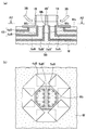
- Fig. 9 is a view describing a state immediately after drawing out of molten metal from a molten metal bath using the manufacturing device shown in Fig. 8, and Fig. 9(a) is a vertical cross-sectional view thereof and Fig. 9(b) is an arrow view along line A2-A2 in Fig. 9(a).
- Fig. 10 is a view describing a state where a part of molten metal drawn out from a molten metal bath using the manufacturing device shown in Fig. 8 is solidified, and Fig. 10(a) is a vertical cross-sectional view thereof and Fig. 10(b) is an arrow view along line B2-B2 in Fig. 10(a).
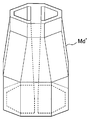
- Fig. 11 is a perspective view showing an embodiment 2 of a casting manufactured by the manufacturing device shown in Fig. 8.
- a manufacturing device 10B of the embodiment 2 shown in Fig. 8 is different from the manufacturing device 10A of the embodiment 1 shown in Fig. 4 in the mode of outer contour defining members 4aB for defining the outer contour of a casting, and other elements are substantially the same.
- the outer contour defining members 4aB are each made of a rectangular plate, and the whole outer periphery of a formed body can be defined by the outer contour defining members 4aB by parts of adjacent outer contour defining members 4aB overlapping each other.
- the manufacturing device 10B shown in Fig. 8 includes a molten metal bath 2B for storing molten metal M, cooling means 3B for solidifying molten metal drawn out from a bath surface Ma of the molten metal M in the molten metal bath 2B, an outer contour unit 4B configured from a plurality of outer contour defining members 4aB for defining the outer contour of a casting, the outer contour unit 4B being arranged in a region between the bath surface Ma of the molten metal bath 2B and a solid region where the molten metal M is solidified by the cooling means 3B, an inner contour unit 5B configured from a plurality of inner contour defining members 5aB for defining the inner contour of the casting, the inner contour unit 5B being arranged on the inner side than the outer contour unit 4B, and moving means 6B for individually moving the plurality of outer contour defining members 4aB and the plurality of inner contour defining members 5aB according to drawing out of the molten metal. Additionally, also in the embodiment 2, as in the embodiment
- the outer contour defining members 4aB constituting the outer contour unit 4B are formed of substantially rectangular plates, and are made to contact molten metal M drawn out from the bath surface Ma in a planar fashion. Also, inner contour defining members 5aB' for forming a rib are provided at a center portion of the inner contour defining members 5aB constituting the inner contour unit 5B.
- the plurality of outer contour defining members 4aB constituting the outer contour unit 4B and the plurality of inner contour defining members 5aB constituting the inner contour unit 5B are arranged concentrically, and the plurality of outer contour defining members 4aB and the plurality of inner contour defining members 5aB are moved in synchronization according to the drawing out of the molten metal M. Additionally, parts of adjacent outer contour defining members 4aB are arranged overlapping each other, and thus, the whole outer periphery of a formed body can be defined by the outer contour defining members 4aB even when the outer contour defining members 4aB are moved.
- FIG. 9(a) An induction body 1B having a joint portion 1B' for forming a rib provided on a substantially hexagonal tube is brought into contact with the molten metal M stored in the molten metal bath 2B and the induction body 1B is separated from the bath surface Ma of the molten metal M in the molten metal bath 2B, to thereby draw out the molten metal M from the bath surface Ma of the molten metal bath 2B.
- Fig. 9(a) an induction body 1B having a joint portion 1B' for forming a rib provided on a substantially hexagonal tube is brought into contact with the molten metal M stored in the molten metal bath 2B and the induction body 1B is separated from the bath surface Ma of the molten metal M in the molten metal bath 2B, to thereby draw out the molten metal M from the bath surface Ma of the molten metal bath 2B.
- Fig. 9(a) an induction body 1B having a joint portion 1B' for
- the plurality of outer contour defining members 4aB and the plurality of inner contour defining members 5aB and 5aB' are arranged, and the molten metal M drawn out from the bath surface Ma of the molten metal M in the molten metal bath 2B is drawn out through a region determined by the plurality of outer contour defining members 4aB and the plurality of inner contour defining members 5aB and a region determined by the plurality of inner contour defining member 5aB', and therefore, a retained molten metal Mb having a substantially hexagonal cross section and a rib portion is formed between the induction body 1B and the bath surface Ma of the molten metal M in the molten metal bath 2B.
- the induction body 1B is moved so as to be separated from the bath surface Ma of the molten metal bath 2B, and the retained molten metal Mb in a semi-solid state that is formed between the induction body 1B and the bath surface Ma of the molten metal bath 2B is solidified using the cooling means 3B to form molten metal Mc in a solid state.
- the plurality of outer contour defining members 4aB and the plurality of inner contour defining members 5aB and 5aB' are each moved by the moving means 6B (see Fig. 8) in synchronization with the drawing out of the molten metal M from the bath surface Ma.
- the plurality of outer contour defining members 4aB and the plurality of inner contour defining members 5aB are moved in the direction of expansion in the radial direction, causing the outer periphery to be gradually larger. Also, the plurality of outer contour defining members 4aB move greater than the plurality of inner contour defining members 5aB, and the thickness is made to gradually increase. Furthermore, the plurality of inner contour defining members 5aB' move inward to form the rib portion, and the thickness of the rib portion is gradually reduced.
- a casting Md' of the embodiment 2 whose cross section is substantially hexagonal and whose thickness is greater as it gets nearer to the lower end portion, and within which a rib portion is formed, the thickness of the rib portion becoming less as it gets nearer to the lower end portion, is manufactured.
Landscapes
- Engineering & Computer Science (AREA)
- Mechanical Engineering (AREA)
- Continuous Casting (AREA)
- Molds, Cores, And Manufacturing Methods Thereof (AREA)
Priority Applications (5)
| Application Number | Priority Date | Filing Date | Title |
|---|---|---|---|
| BR112014022903-1A BR112014022903B1 (pt) | 2012-03-16 | 2013-03-13 | Método de fabricação de peça fundida, dispositivo de fabricação da mesma e peça fundida |
| AU2013233733A AU2013233733B2 (en) | 2012-03-16 | 2013-03-13 | Manufacturing method of casting, manufacturing device thereof, and casting |
| US14/385,600 US9700935B2 (en) | 2012-03-16 | 2013-03-13 | Manufacturing method of casting, manufacturing device thereof, and casting |
| GB1417764.6A GB2515227A (en) | 2012-03-16 | 2013-03-13 | Manufacturing method of casting, manufacturing device thereof, and casting |
| CN201380014649.2A CN104254414B (zh) | 2012-03-16 | 2013-03-13 | 铸件的制造方法、其制造设备和铸件 |
Applications Claiming Priority (2)
| Application Number | Priority Date | Filing Date | Title |
|---|---|---|---|
| JP2012-061030 | 2012-03-16 | ||
| JP2012061030A JP5755591B2 (ja) | 2012-03-16 | 2012-03-16 | 鋳造体の製造方法とその製造装置 |
Publications (1)
| Publication Number | Publication Date |
|---|---|
| WO2013136785A1 true WO2013136785A1 (fr) | 2013-09-19 |
Family
ID=48142043
Family Applications (1)
| Application Number | Title | Priority Date | Filing Date |
|---|---|---|---|
| PCT/JP2013/001642 Ceased WO2013136785A1 (fr) | 2012-03-16 | 2013-03-13 | Procédé de fabrication de coulée, dispositif de fabrication associé et coulée |
Country Status (7)
| Country | Link |
|---|---|
| US (1) | US9700935B2 (fr) |
| JP (1) | JP5755591B2 (fr) |
| CN (1) | CN104254414B (fr) |
| AU (1) | AU2013233733B2 (fr) |
| BR (1) | BR112014022903B1 (fr) |
| GB (1) | GB2515227A (fr) |
| WO (1) | WO2013136785A1 (fr) |
Cited By (8)
| Publication number | Priority date | Publication date | Assignee | Title |
|---|---|---|---|---|
| WO2015072073A1 (fr) * | 2013-11-15 | 2015-05-21 | Toyota Jidosha Kabushiki Kaisha | Appareil de coulée en continu de type à tirage vers le haut et procédé de coulée en continu de type à tirage vers le haut |
| WO2015079822A1 (fr) * | 2013-11-26 | 2015-06-04 | Toyota Jidosha Kabushiki Kaisha | Procédé de coulée continue à traction ascendante et appareil de coulée continue à traction ascendante |
| WO2015079810A1 (fr) * | 2013-11-26 | 2015-06-04 | Toyota Jidosha Kabushiki Kaisha | Appareil et procede de coulage en continu du type a extraction |
| WO2015079614A1 (fr) * | 2013-11-27 | 2015-06-04 | Toyota Jidosha Kabushiki Kaisha | Appareil de coulée continue du type à traction vers le haut et procédé de coulée continue du type à traction vers le haut |
| WO2015136347A1 (fr) * | 2014-03-10 | 2015-09-17 | Toyota Jidosha Kabushiki Kaisha | Appareil de coulée continue à étirage par le haut et procédé de coulée continue à étirage par le haut |
| WO2015145252A1 (fr) * | 2014-03-28 | 2015-10-01 | Toyota Jidosha Kabushiki Kaisha | Procédé de coulée continue à étirage par le haut et appareil de coulée continue à étirage par le haut |
| US9931692B2 (en) | 2012-11-22 | 2018-04-03 | Toyota Jidosha Kabushiki Kaisha | Hoisting type continuous casting device, hoisting type continuous casting method, and solidification interface detection device |
| EP3092093B1 (fr) * | 2014-01-08 | 2019-11-13 | Toyota Jidosha Kabushiki Kaisha | Appareil de coulée continue à étirage par le haut et procédé de coulée continue à étirage par le haut |
Families Citing this family (4)
| Publication number | Priority date | Publication date | Assignee | Title |
|---|---|---|---|---|
| JP5730836B2 (ja) * | 2012-10-31 | 2015-06-10 | トヨタ自動車株式会社 | リブ付パイプ及びその製造方法 |
| JP6119578B2 (ja) | 2013-11-26 | 2017-04-26 | トヨタ自動車株式会社 | 引上式連続鋳造装置及び引上式連続鋳造方法 |
| JP6701615B2 (ja) * | 2014-03-10 | 2020-05-27 | トヨタ自動車株式会社 | 引上式連続鋳造装置及び引上式連続鋳造方法 |
| JP6187393B2 (ja) * | 2014-06-13 | 2017-08-30 | トヨタ自動車株式会社 | 車両用バンパ |
Citations (5)
| Publication number | Priority date | Publication date | Assignee | Title |
|---|---|---|---|---|
| JPS59203798A (ja) * | 1983-04-30 | 1984-11-17 | Toshiba Corp | 帯状シリコン結晶製造装置 |
| JPS63199050A (ja) | 1987-02-13 | 1988-08-17 | Natl Res Inst For Metals | 鋳型を使用しない引上げ連鋳法及びその装置 |
| JPH02251341A (ja) | 1989-03-25 | 1990-10-09 | Kubota Ltd | 引上げ連続鋳造装置 |
| JPH09248657A (ja) | 1996-03-19 | 1997-09-22 | Toyota Motor Corp | 成形方法および成形装置 |
| WO2012035752A1 (fr) * | 2010-09-17 | 2012-03-22 | Kabushiki Kaisha Toyota Chuo Kenkyusho | Procédé de coulée libre, appareil de coulée libre, et pièce coulée |
Family Cites Families (8)
| Publication number | Priority date | Publication date | Assignee | Title |
|---|---|---|---|---|
| JPS58103941A (ja) * | 1981-12-16 | 1983-06-21 | Atsumi Ono | 鏡面を有する金属成形体の連続製造法及びその装置 |
| JPS59130649A (ja) * | 1983-01-14 | 1984-07-27 | O C C:Kk | 鋳造途中で断面形状を変化できる鋳塊の連続鋳造法及び鋳型 |
| JPH02205232A (ja) * | 1989-02-01 | 1990-08-15 | Natl Res Inst For Metals | 引上げ連続鋳造法とその装置 |
| JP2893745B2 (ja) * | 1989-08-17 | 1999-05-24 | 大同特殊鋼株式会社 | 連続鋳造の方法および装置 |
| CN1718314A (zh) * | 2005-07-12 | 2006-01-11 | 天津世星电子材料有限公司 | 铝硅键合线的无模连铸工艺方法 |
| US20090050290A1 (en) * | 2007-08-23 | 2009-02-26 | Anderson Michael K | Automated variable dimension mold and bottom block system |
| CN101116902A (zh) * | 2007-08-29 | 2008-02-06 | 高新张铜股份有限公司 | 硅青铜棒坯的上引铸造装置 |
| CN201120460Y (zh) * | 2007-10-31 | 2008-09-24 | 台湾精微材料股份有限公司 | 双引式连续铸造装置 |
-
2012
- 2012-03-16 JP JP2012061030A patent/JP5755591B2/ja active Active
-
2013
- 2013-03-13 US US14/385,600 patent/US9700935B2/en not_active Expired - Fee Related
- 2013-03-13 GB GB1417764.6A patent/GB2515227A/en not_active Withdrawn
- 2013-03-13 AU AU2013233733A patent/AU2013233733B2/en not_active Ceased
- 2013-03-13 CN CN201380014649.2A patent/CN104254414B/zh not_active Expired - Fee Related
- 2013-03-13 WO PCT/JP2013/001642 patent/WO2013136785A1/fr not_active Ceased
- 2013-03-13 BR BR112014022903-1A patent/BR112014022903B1/pt not_active IP Right Cessation
Patent Citations (5)
| Publication number | Priority date | Publication date | Assignee | Title |
|---|---|---|---|---|
| JPS59203798A (ja) * | 1983-04-30 | 1984-11-17 | Toshiba Corp | 帯状シリコン結晶製造装置 |
| JPS63199050A (ja) | 1987-02-13 | 1988-08-17 | Natl Res Inst For Metals | 鋳型を使用しない引上げ連鋳法及びその装置 |
| JPH02251341A (ja) | 1989-03-25 | 1990-10-09 | Kubota Ltd | 引上げ連続鋳造装置 |
| JPH09248657A (ja) | 1996-03-19 | 1997-09-22 | Toyota Motor Corp | 成形方法および成形装置 |
| WO2012035752A1 (fr) * | 2010-09-17 | 2012-03-22 | Kabushiki Kaisha Toyota Chuo Kenkyusho | Procédé de coulée libre, appareil de coulée libre, et pièce coulée |
Cited By (15)
| Publication number | Priority date | Publication date | Assignee | Title |
|---|---|---|---|---|
| US9931692B2 (en) | 2012-11-22 | 2018-04-03 | Toyota Jidosha Kabushiki Kaisha | Hoisting type continuous casting device, hoisting type continuous casting method, and solidification interface detection device |
| WO2015072073A1 (fr) * | 2013-11-15 | 2015-05-21 | Toyota Jidosha Kabushiki Kaisha | Appareil de coulée en continu de type à tirage vers le haut et procédé de coulée en continu de type à tirage vers le haut |
| US9751128B2 (en) | 2013-11-26 | 2017-09-05 | Toyota Jidosha Kabushiki Kaisha | Pulling-up-type continuous casting apparatus and pulling-up-type continuous casting method |
| CN105764631A (zh) * | 2013-11-26 | 2016-07-13 | 丰田自动车株式会社 | 上引式连续铸造方法和上引式连续铸造装置 |
| CN105764632A (zh) * | 2013-11-26 | 2016-07-13 | 丰田自动车株式会社 | 上引式连续铸造设备以及上引式连续铸造方法 |
| WO2015079810A1 (fr) * | 2013-11-26 | 2015-06-04 | Toyota Jidosha Kabushiki Kaisha | Appareil et procede de coulage en continu du type a extraction |
| CN105764632B (zh) * | 2013-11-26 | 2018-02-13 | 丰田自动车株式会社 | 上引式连续铸造设备以及上引式连续铸造方法 |
| WO2015079822A1 (fr) * | 2013-11-26 | 2015-06-04 | Toyota Jidosha Kabushiki Kaisha | Procédé de coulée continue à traction ascendante et appareil de coulée continue à traction ascendante |
| WO2015079614A1 (fr) * | 2013-11-27 | 2015-06-04 | Toyota Jidosha Kabushiki Kaisha | Appareil de coulée continue du type à traction vers le haut et procédé de coulée continue du type à traction vers le haut |
| EP3092093B1 (fr) * | 2014-01-08 | 2019-11-13 | Toyota Jidosha Kabushiki Kaisha | Appareil de coulée continue à étirage par le haut et procédé de coulée continue à étirage par le haut |
| WO2015136347A1 (fr) * | 2014-03-10 | 2015-09-17 | Toyota Jidosha Kabushiki Kaisha | Appareil de coulée continue à étirage par le haut et procédé de coulée continue à étirage par le haut |
| WO2015145252A1 (fr) * | 2014-03-28 | 2015-10-01 | Toyota Jidosha Kabushiki Kaisha | Procédé de coulée continue à étirage par le haut et appareil de coulée continue à étirage par le haut |
| CN106102961A (zh) * | 2014-03-28 | 2016-11-09 | 丰田自动车株式会社 | 上引式连续铸造方法和上引式连续铸造装置 |
| CN106102961B (zh) * | 2014-03-28 | 2018-01-02 | 丰田自动车株式会社 | 上引式连续铸造方法和上引式连续铸造装置 |
| US10512969B2 (en) | 2014-03-28 | 2019-12-24 | Toyota Jidosha Kabushiki Kaisha | Up-drawing continuous casting method and up-drawing continuous casting apparatus |
Also Published As
| Publication number | Publication date |
|---|---|
| GB2515227A (en) | 2014-12-17 |
| AU2013233733B2 (en) | 2015-08-20 |
| GB201417764D0 (en) | 2014-11-19 |
| US20150071817A1 (en) | 2015-03-12 |
| CN104254414B (zh) | 2016-08-17 |
| CN104254414A (zh) | 2014-12-31 |
| BR112014022903B1 (pt) | 2019-07-09 |
| JP2013193098A (ja) | 2013-09-30 |
| AU2013233733A1 (en) | 2014-09-25 |
| JP5755591B2 (ja) | 2015-07-29 |
| US9700935B2 (en) | 2017-07-11 |
Similar Documents
| Publication | Publication Date | Title |
|---|---|---|
| AU2013233733B2 (en) | Manufacturing method of casting, manufacturing device thereof, and casting | |
| EP3328575B1 (fr) | Conception de tube de cuivre simple pour procédé de coulée continue à rigidité accrue | |
| CN103328130B (zh) | 用于连续铸造的结晶器 | |
| CN106513572B (zh) | 3d打印砂型及其制造方法 | |
| JP2008238228A (ja) | 金型鋳造装置 | |
| KR101689901B1 (ko) | 액체 금속 캐스팅 장치를 위한 레이들 슈라우드 | |
| CN206474647U (zh) | 一种预埋在砂型中的芯撑 | |
| JP6036671B2 (ja) | 引上式連続鋳造方法、及び引上式連続鋳造装置 | |
| WO2015072074A1 (fr) | Appareil de coulée continue de type à tirage et procédé de coulée continue de type à tirage | |
| JP6442058B2 (ja) | 連続鋳造用セグメント | |
| JP5836837B2 (ja) | 鋳造用金型 | |
| WO2014045116A2 (fr) | Appareil de coulée continue à étirage par le haut et procédé de coulée continue à étirage par le haut | |
| JP2015182113A (ja) | インゴット鋳造装置 | |
| US9713840B2 (en) | Pipe with rib and method for manufacturing pipe with rib | |
| JP6330375B2 (ja) | アルミニウム合金鋳造素材の製造装置 | |
| WO2014118611A1 (fr) | Appareil de coulée en continu à tirage vers le haut et procédé de coulée en continu à tirage vers le haut | |
| KR101503444B1 (ko) | 주형 및 이를 이용한 연속 주조 방법 | |
| US10512969B2 (en) | Up-drawing continuous casting method and up-drawing continuous casting apparatus | |
| JP6882947B2 (ja) | アルミニウムの連続鋳造装置 | |
| WO2017155038A1 (fr) | Dispositif de coulée | |
| JP6295814B2 (ja) | 連続鋳造装置の軽圧下装置および連続鋳造方法 | |
| JP2015167954A (ja) | アルミニウム合金鋳造素材の製造装置 | |
| KR20130002510A (ko) | 쉬라우드 노즐 고정 장치 | |
| ITBS20120016A1 (it) | Lingottiera di un impianto per colata continua | |
| JP2006305593A (ja) | 鍛造用金型のダイス |
Legal Events
| Date | Code | Title | Description |
|---|---|---|---|
| 121 | Ep: the epo has been informed by wipo that ep was designated in this application |
Ref document number: 13717330 Country of ref document: EP Kind code of ref document: A1 |
|
| WWE | Wipo information: entry into national phase |
Ref document number: 14385600 Country of ref document: US |
|
| ENP | Entry into the national phase |
Ref document number: 2013233733 Country of ref document: AU Date of ref document: 20130313 Kind code of ref document: A |
|
| ENP | Entry into the national phase |
Ref document number: 1417764 Country of ref document: GB Kind code of ref document: A Free format text: PCT FILING DATE = 20130313 |
|
| REG | Reference to national code |
Ref country code: BR Ref legal event code: B01A Ref document number: 112014022903 Country of ref document: BR |
|
| NENP | Non-entry into the national phase |
Ref country code: DE |
|
| 122 | Ep: pct application non-entry in european phase |
Ref document number: 13717330 Country of ref document: EP Kind code of ref document: A1 |
|
| ENP | Entry into the national phase |
Ref document number: 112014022903 Country of ref document: BR Kind code of ref document: A2 Effective date: 20140916 |