WO2013137142A1 - 二次電池の充電装置および二次電池の充電方法 - Google Patents
二次電池の充電装置および二次電池の充電方法 Download PDFInfo
- Publication number
- WO2013137142A1 WO2013137142A1 PCT/JP2013/056464 JP2013056464W WO2013137142A1 WO 2013137142 A1 WO2013137142 A1 WO 2013137142A1 JP 2013056464 W JP2013056464 W JP 2013056464W WO 2013137142 A1 WO2013137142 A1 WO 2013137142A1
- Authority
- WO
- WIPO (PCT)
- Prior art keywords
- charging
- secondary battery
- power
- full charge
- stop time
- Prior art date
- Legal status (The legal status is an assumption and is not a legal conclusion. Google has not performed a legal analysis and makes no representation as to the accuracy of the status listed.)
- Ceased
Links
Images




Classifications
-
- H—ELECTRICITY
- H02—GENERATION; CONVERSION OR DISTRIBUTION OF ELECTRIC POWER
- H02J—ELECTRIC POWER NETWORKS; CIRCUIT ARRANGEMENTS OR SYSTEMS FOR SUPPLYING OR DISTRIBUTING ELECTRIC POWER; SYSTEMS FOR STORING ELECTRIC ENERGY
- H02J7/00—Circuit arrangements for charging or discharging batteries or for supplying loads from batteries
- H02J7/90—Regulation of charging or discharging current or voltage
- H02J7/933—Regulation of charging or discharging current or voltage the cycle being controlled or terminated in response to electric parameters
-
- G—PHYSICS
- G01—MEASURING; TESTING
- G01R—MEASURING ELECTRIC VARIABLES; MEASURING MAGNETIC VARIABLES
- G01R31/00—Arrangements for testing electric properties; Arrangements for locating electric faults; Arrangements for electrical testing characterised by what is being tested not provided for elsewhere
- G01R31/36—Arrangements for testing, measuring or monitoring the electrical condition of accumulators or electric batteries, e.g. capacity or state of charge [SoC]
- G01R31/382—Arrangements for monitoring battery or accumulator variables, e.g. SoC
-
- H—ELECTRICITY
- H01—ELECTRIC ELEMENTS
- H01M—PROCESSES OR MEANS, e.g. BATTERIES, FOR THE DIRECT CONVERSION OF CHEMICAL ENERGY INTO ELECTRICAL ENERGY
- H01M10/00—Secondary cells; Manufacture thereof
- H01M10/42—Methods or arrangements for servicing or maintenance of secondary cells or secondary half-cells
- H01M10/44—Methods for charging or discharging
- H01M10/443—Methods for charging or discharging in response to temperature
-
- H—ELECTRICITY
- H02—GENERATION; CONVERSION OR DISTRIBUTION OF ELECTRIC POWER
- H02J—ELECTRIC POWER NETWORKS; CIRCUIT ARRANGEMENTS OR SYSTEMS FOR SUPPLYING OR DISTRIBUTING ELECTRIC POWER; SYSTEMS FOR STORING ELECTRIC ENERGY
- H02J7/00—Circuit arrangements for charging or discharging batteries or for supplying loads from batteries
- H02J7/90—Regulation of charging or discharging current or voltage
- H02J7/971—Regulation of charging or discharging current or voltage the charge cycle being controlled or terminated in response to non-electric parameters
- H02J7/975—Regulation of charging or discharging current or voltage the charge cycle being controlled or terminated in response to non-electric parameters in response to temperature
- H02J7/977—Regulation of charging or discharging current or voltage the charge cycle being controlled or terminated in response to non-electric parameters in response to temperature of the battery
-
- H—ELECTRICITY
- H02—GENERATION; CONVERSION OR DISTRIBUTION OF ELECTRIC POWER
- H02J—ELECTRIC POWER NETWORKS; CIRCUIT ARRANGEMENTS OR SYSTEMS FOR SUPPLYING OR DISTRIBUTING ELECTRIC POWER; SYSTEMS FOR STORING ELECTRIC ENERGY
- H02J7/00—Circuit arrangements for charging or discharging batteries or for supplying loads from batteries
- H02J7/90—Regulation of charging or discharging current or voltage
- H02J7/927—Regulation of charging or discharging current or voltage with introduction of pulses during the charging process
-
- Y—GENERAL TAGGING OF NEW TECHNOLOGICAL DEVELOPMENTS; GENERAL TAGGING OF CROSS-SECTIONAL TECHNOLOGIES SPANNING OVER SEVERAL SECTIONS OF THE IPC; TECHNICAL SUBJECTS COVERED BY FORMER USPC CROSS-REFERENCE ART COLLECTIONS [XRACs] AND DIGESTS
- Y02—TECHNOLOGIES OR APPLICATIONS FOR MITIGATION OR ADAPTATION AGAINST CLIMATE CHANGE
- Y02B—CLIMATE CHANGE MITIGATION TECHNOLOGIES RELATED TO BUILDINGS, e.g. HOUSING, HOUSE APPLIANCES OR RELATED END-USER APPLICATIONS
- Y02B40/00—Technologies aiming at improving the efficiency of home appliances, e.g. induction cooking or efficient technologies for refrigerators, freezers or dish washers
-
- Y—GENERAL TAGGING OF NEW TECHNOLOGICAL DEVELOPMENTS; GENERAL TAGGING OF CROSS-SECTIONAL TECHNOLOGIES SPANNING OVER SEVERAL SECTIONS OF THE IPC; TECHNICAL SUBJECTS COVERED BY FORMER USPC CROSS-REFERENCE ART COLLECTIONS [XRACs] AND DIGESTS
- Y02—TECHNOLOGIES OR APPLICATIONS FOR MITIGATION OR ADAPTATION AGAINST CLIMATE CHANGE
- Y02E—REDUCTION OF GREENHOUSE GAS [GHG] EMISSIONS, RELATED TO ENERGY GENERATION, TRANSMISSION OR DISTRIBUTION
- Y02E60/00—Enabling technologies; Technologies with a potential or indirect contribution to GHG emissions mitigation
- Y02E60/10—Energy storage using batteries
Definitions
- the present invention relates to charge control of a secondary battery.
- a charging device for charging a secondary battery there is known a charging device that stops charging when a fully charged state is detected after the start of charging, and charges again after a predetermined time has elapsed (for example, JP2005-124340A). In this manner, by stopping charging for a predetermined time after detecting the apparent full charge state and performing charging again, the actual charge state of the battery can be brought close to the full charge state.
- charging stop time In a configuration in which charging is stopped after a fully charged state is detected (hereinafter referred to as charging stop time) in advance, as in a charging device of JP2005-124340A, an appropriate charging stop time can be set. difficult. If the charging stop time is too short, the actual charged state of the secondary battery cannot be sufficiently brought close to the fully charged state. On the other hand, if the charging stop time is too long, the time from the start of charging to the end of recharging becomes unnecessarily long.
- an object of the present invention is to set an appropriate charging stop time and efficiently charge the secondary battery.
- a charging power source that supplies power to the secondary battery, a charging power detection unit that detects power charged in the secondary battery by the charging power source, and a detection value of the charging power detection unit
- a charging device for a secondary battery includes a full charge determination unit that performs a full charge determination when the rechargeable power calculated in this way becomes equal to or lower than a predetermined power set in advance.
- the secondary battery charger supplies power from the charging power source to the secondary battery until it is determined to be fully charged, and stops charging power from the charging power source to the secondary battery when it is determined to be fully charged.
- charging control means for performing charging until a full charge is determined again after a predetermined time has elapsed from the stop of power supply.
- the charging device for the secondary battery includes a temperature detecting means for detecting the temperature of the secondary battery, and a stop time setting means for setting a stop time based on the temperature of the secondary battery at least when the full charge determination is made.
- the stop time setting means sets the stop time longer as the temperature of the secondary battery is lower.
- FIG. 1 is a configuration diagram of a charging system according to the present embodiment.
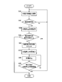
- FIG. 2 is a flowchart of the charge control routine according to the first embodiment.
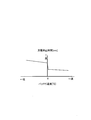
- FIG. 3 is a stop time map.
- FIG. 4 is a time chart when charging control is executed.
- FIG. 5 is a time chart for explaining the effects of the first embodiment.
- FIG. 6 is a flowchart of a charge control routine according to the second embodiment.
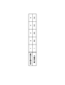
- FIG. 7 is a correction coefficient table for correcting charging stop time.
- FIG. 1 is a configuration diagram of a charging system according to an embodiment of the present invention.
- the charging system includes a battery 3, a charger 2 that supplies charging power to the battery 3, and a controller 1 that controls the charger 2. Furthermore, a current sensor 4 that detects a charging current supplied from the charger 2 to the battery 3, a voltage sensor 5 that detects the battery voltage, and a temperature sensor 6 that detects the temperature of the battery 3 are provided.
- the controller 1 calculates the power charged from the charger 2 to the battery 3 based on the detection values of the current sensor 4 and the voltage sensor 5, and sends a charging power command based on the calculated charging power to the charger 2. Also, the detection value of the temperature sensor 6 is read.
- the internal configuration of the controller 1 will be described later.
- the charger 2 supplies the battery 3 with charging power based on the charging power command from the controller 1.
- the battery 3 is a secondary battery such as a lithium ion battery used as a power source for driving a drive motor of an electric vehicle, for example, and is charged by charging power supplied from the charger 2.
- Detected values of the current sensor 4, voltage sensor 5, and temperature sensor 6 are read into the controller 1.
- the controller 1 includes a chargeable power calculation unit 11, a charge power command unit 10, a timer 12, and a stop time setting unit 13.
- the chargeable power calculation unit 11 reads the detection values of the current sensor 4 and the voltage sensor 5 and calculates chargeable power based on these values.
- the chargeable power means power that can charge the battery 3 until the battery 3 is fully charged.
- the charge power command unit 10 sends a charge power command based on the chargeable power calculated by the chargeable power calculation unit 11 to the charger 2.
- the charge power command unit 10 determines that the battery is fully charged when the chargeable power calculated by the chargeable power calculation unit 11 is equal to or lower than a predetermined power set in advance, and stops charging. Set the power command to zero [kW]. Furthermore, when it is determined that the battery is fully charged, a command for setting the charging stop time to the stop time setting unit 13 (hereinafter referred to as a stop time setting command) is sent.
- a stop time setting command is sent, a count value of a timer 12 to be described later is read. When the count value becomes zero, sending of a charge power command based on chargeable power to the charger 2 is resumed, so-called additional charging. To do.
- the stop time setting unit 13 When the stop time setting unit 13 receives a stop time setting command from the charging power command unit 10, the stop time setting unit 13 calculates a stop time according to the battery temperature and sets the calculated stop time in the timer 12. Although details will be described later, the stop time corresponding to the battery temperature is longer as the battery temperature is lower.
- the timer 12 starts counting down (a process for decreasing the count value every predetermined time). However, the minimum count value is zero.
- FIG. 2 is a flowchart of a charging control routine executed by the controller 1.
- step S10 the controller 1 calculates chargeable power. More specifically, the chargeable power calculation unit 11 calculates chargeable power based on the detection value of the current sensor 4 and the detection value of the voltage sensor 5, and sends this chargeable power to the charge power command unit 10 for charging. The power command unit 10 sends a charge power command to the charger 2.
- a deviation between a predetermined full charge voltage and a detection value of the voltage sensor 5, that is, a voltage increase margin ⁇ V until the full charge state is calculated.
- the current increase allowance ⁇ I until the fully charged state is calculated using the voltage increase allowance ⁇ V and the resistance R of the battery 3 measured in advance. Then, it is possible to calculate a power increase allowance from the voltage increase allowance ⁇ V and the current increase allowance ⁇ I to the fully charged state, that is, chargeable power.
- step S20 the controller 1 determines whether or not the charging power command unit 10 is in a fully charged state. Specifically, when the chargeable power becomes equal to or lower than a predetermined power, it is determined that the battery is fully charged (hereinafter, this determination is referred to as “full charge determination”).
- the predetermined power may be set to zero [kW] for the purpose of determination in this step, but the chargeable power does not decrease to zero due to the detection error of each sensor 4, 5 and the like in a fully charged state. There is a risk that it will not be determined. Therefore, a value close to zero [kW] is set so that it can be determined that the sensor is fully charged even if there is an error in each of the sensors 4 and 5.
- step S30 is executed. If the full charge is not determined, the process of step S10 is executed again.
- the full charge determination is merely a determination that the chargeable power is equal to or lower than the predetermined power, and is not a determination that the battery 3 is actually in a fully charged state.
- step S30 the controller 1 sets the charge stop time after the full charge determination in the stop time setting unit 13.
- the stop time setting unit 13 reads the detection value of the temperature sensor 6, determines the stop time by referring to a previously stored stop time map, sets the determined set time in the timer 12, and sets the timer 12 Start the countdown.
- a longer stop time is set as the battery temperature decreases. This is based on the characteristic that the lower the battery temperature, the longer the time until polarization is eliminated. For example, in the case of a lithium ion battery, the polarization is caused by a concentration difference caused by diffusion of lithium ions as a diffusing material. The lower the battery temperature, the higher the viscosity of the electrolyte solution, and it takes time to eliminate the concentration difference. Therefore, by setting the charging time longer as the battery temperature is lower, polarization is sufficiently eliminated before charging is resumed.
- the stop time map is not limited to FIG. 3 as long as the condition that the longer stop time is set as the battery temperature is lower is satisfied.
- the temperature region may be divided into a plurality of sections and a stop time may be set for each section.
- step S40 the controller 1 refers to the value of the full charge determination number counter provided in the charging power command unit 10, and determines whether or not the full charge determination number is equal to or greater than a predetermined number of times.
- the specified number of times can be set arbitrarily, but is set to about 5 times, for example. If it is less than the specified number of times, the process of step S50 is executed.
- step S50 the controller 1 increments the value of the full charge determination number counter.
- the full charge determination number counter increments the counter value every time the full charge determination is made in step S20 until it is determined in step S40 that the counter value is not less than the specified number.
- step S60 the controller 1 transmits the charging power command value to zero [kW] at the charging power command unit 10 to the charger 2 to stop charging.
- step S70 the controller 1 determines whether or not the charging stop time has elapsed in the charging power command unit 10. Specifically, it is determined whether or not the counter value of the timer 12 has become zero. If the charging stop time has elapsed, the process of step S10 is executed again for additional charging, and if the charging stop time has not elapsed, the process of step S60 is executed again.
- FIG. 4 is a time chart when the above charging control is executed.
- the chargeable power is a constant value until timing T1. This is because a larger chargeable power is calculated in the calculation but is limited by P1, which is the upper limit of the supply capability of the charger 2.
- the chargeable power starts to decrease from the timing T1 when the battery voltage approaches the full charge voltage, and the full charge determination is made at the timing T2 when the battery voltage becomes equal to or less than P2, which is a predetermined value set for determining whether or not the battery is fully charged. Charging stops temporarily. Then, additional charging is started from timing T3 after the charging stop time has elapsed. Thereafter, the charging is repeatedly stopped and restarted until the full charge determination reaches the specified number of times.
- FIG. 5 is a time chart of the amount of power charged in the battery 3.
- the solid line in the figure shows the case where the charging control of this embodiment is executed.
- the case where the charging stop time is constant regardless of the battery temperature is indicated by a broken line.
- the battery temperature is, for example, near zero [° C.].
- the power amount increases in the same manner as in the present embodiment and the comparative example, and the charging is stopped.
- the charging stop time is set according to the battery temperature
- the charging is restarted at timing T3
- follow-up charging is performed at timing T2 earlier than timing T3. Has started.
- the charge stop time is set such that the polarization can be sufficiently eliminated according to the battery temperature, whereas in the comparative example, the charge stop time is constant regardless of the battery temperature, so the polarization is sufficiently eliminated. This is because charging is resumed in a state in which it is not performed. The same trend continues after the second full charge determination.
- a temperature sensor 6 that detects the temperature of the battery 3 and a stop time setting unit 13 that sets a charge stop time based on at least the battery temperature when the full charge determination is made are provided.
- the charging stop time is longer, and the amount of power charged by additional charging is increased, so that charging can be performed efficiently.
- ⁇ Charging is terminated when the number of full charge determinations reaches a preset specified number, so additional charging is not repeated in vain.
- the charging system of the second embodiment is similar to the first embodiment in that the charging system stops charging after full charge determination and performs additional charging when the charging stop time set based on the battery temperature has elapsed. It differs from the first embodiment in that the charging stop time is corrected based on the number of times of determination.
- FIG. 6 is a flowchart showing an example of a charge control routine performed by the controller 1 in the second embodiment.
- the difference from the flowchart of FIG. 2 is that after the number of full charge determinations is counted in step S50, a part for executing step S55 for correcting the charge stop time according to the number of charge determinations, and the charge stop after correction in step S75. This is a part for determining whether or not time has elapsed.
- step S55 the controller 1 corrects the charging stop time set in step S30 to be shorter as the number of full charge determinations increases. Specifically, as in the first embodiment, the charging stop time set in step S30 is multiplied by a correction coefficient ⁇ of 1 or less that decreases as the full charge determination count increases.
- the correction coefficient ⁇ is determined based on the value of the full charge determination number counter with reference to a table shown in FIG.
- the relationship between the number of full charge determinations in the table of FIG. 7 and the correction coefficient ⁇ is set based on the degree of elimination of polarization after the charge is stopped by an experiment or the like.
- the correction coefficient ⁇ does not change and is a fixed value.
- Step S75 is the same as Step S70 in that it is determined whether or not the charging stop time has elapsed based on whether or not the counter value of the timer 12 has become zero. However, the count value at the start of the countdown is different.
- the secondary battery can be charged more efficiently than in the first embodiment.
- the charge stop time at the time when the full charge determination count reaches the predetermined count is maintained thereafter, so that the fixed charge time is not shortened more than necessary, and is followed up. Charging can be performed.
- the charging method and the full charge determination method are not limited to the above-described embodiment.
- a charge current command based on the chargeable power calculated by the chargeable power calculation unit 11 may be output.
- the charge power command unit 10 sends a value obtained by dividing the chargeable power calculated by the chargeable power calculation unit 11 by the battery voltage as a charge current command is conceivable.
- a charge voltage command based on the chargeable power calculated by the chargeable power calculation unit 11 may be output.
- the chargeable power calculation unit 11 calculates chargeable power based on a predetermined full charge voltage and a battery voltage that are determined in advance, and a predetermined constant full charge voltage until the chargeable power becomes a predetermined value or less. Can be considered as a charging voltage command.
- the chargeable power calculated by the chargeable power calculation unit may be determined to be fully charged when the chargeable power is equal to or less than a predetermined value, and the charge command may be set to zero [kW].
- the rechargeable power calculation unit 11 is configured when the battery voltage becomes a predetermined full charge voltage, or when the deviation between the battery voltage and the predetermined full charge voltage becomes a predetermined value or less. It may be determined that the battery is fully charged.
- the charging system of the present invention is not limited with respect to the charging method and the full charge determination method, and is charged until the battery 3 is in a fully charged state, and the charging is stopped for a predetermined time after becoming fully charged. Any configuration can be used.
Landscapes
- Engineering & Computer Science (AREA)
- Power Engineering (AREA)
- Manufacturing & Machinery (AREA)
- Chemical & Material Sciences (AREA)
- Chemical Kinetics & Catalysis (AREA)
- Electrochemistry (AREA)
- General Chemical & Material Sciences (AREA)
- Physics & Mathematics (AREA)
- General Physics & Mathematics (AREA)
- Charge And Discharge Circuits For Batteries Or The Like (AREA)
- Secondary Cells (AREA)
Abstract
二次電池に電力供給する充電電源と、二次電池に充電される電力を検出する充電電力検出手段と、充電電力検出手段の検出値に基づいて満充電判定をする満充電判定手段と、満充電判定されるまで充電を行ない、満充電判定されたら充電を停止し、充電停止から所定時間経過したら充電を再開し、再び満充電判定されるまで充電を継続するという充電制御を行なう充電制御手段を備える。さらに、二次電池の温度を検出する温度検出手段と、少なくとも満充電判定がされた際の二次電池の温度に基づいて停止時間を設定する停止時間設定手段をさらに備え、停止時間設定手段は温度検出手段の検出温度が低いほど停止時間を長く設定する。
Description
本発明は、二次電池の充電制御に関する。
二次電池を充電する充電装置として、充電開始後に満充電状態を検知したら充電を停止し、予め設定した所定時間経過後に再び充電を行なう充電装置が知られている(例えばJP2005-124340A)。このように、見かけ上の満充電状態を検知した後に所定時間充電を停止し、再び充電を行なうことにより、電池の実際の充電状態を満充電状態に近づけることができる。
しかしながら、JP2005-124340Aの充電装置のように、満充電状態を検知した後の充電を停止する時間(以下、充電停止時間という)を予め設定する構成では、適切な充電停止時間を設定することが難しい。そして、充電停止時間が短すぎると、二次電池の実際の充電状態を充分に満充電状態に近づけることができない。一方、充電停止時間が長すぎると、充電開始から再充電終了までの時間が無駄に長くなる。
本発明の目的は、したがって、適切な充電停止時間を設定し、効率良く二次電池を充電することである。
本発明のある態様によれば、二次電池に電力を供給する充電電源と、充電電源によって二次電池に充電される電力を検出する充電電力検出手段と、充電電力検出手段の検出値に基づいて算出した充電可能電力が予め設定した所定電力以下になった場合に満充電判定をする満充電判定手段を備える二次電池の充電装置が提供される。また、二次電池の充電装置は、満充電判定されるまで充電電源から二次電池へ電力を供給して充電を行ない、満充電判定されたら充電電源から二次電池への電力供給を停止し、電力供給の停止から所定時間経過したら充電を再開して再び満充電判定されるまで充電を行なう充電制御手段を備える。そして、二次電池の充電装置は、二次電池の温度を検出する温度検出手段と、少なくとも満充電判定がされた際の二次電池の温度に基づいて停止時間を設定する停止時間設定手段とをさらに備え、停止時間設定手段は二次電池の温度が低いほど停止時間を長く設定する。
この発明の実施形態、本発明の利点については、添付された図面を参照しながら以下に詳細に説明する。
(第1実施形態)
図1は本発明の実施形態による充電システムの構成図である。
図1は本発明の実施形態による充電システムの構成図である。
充電システムは、バッテリ3と、バッテリ3に充電電力を供給する充電器2と、充電器2を制御するコントローラ1とを含んで構成される。さらに、充電器2からバッテリ3へ供給される充電電流を検出する電流センサ4と、バッテリ電圧を検出する電圧センサ5と、バッテリ3の温度を検出する温度センサ6を備える。
コントローラ1は、充電器2からバッテリ3へ充電される電力を、電流センサ4、電圧センサ5の検出値に基づいて算出し、算出した充電電力に基づく充電電力指令を充電器2に送出する。また、温度センサ6の検出値も読み込む。コントローラ1の内部構成については後述する。
充電器2は、コントローラ1からの充電電力指令に基づいた充電電力をバッテリ3に供給する。
バッテリ3は、例えば電動車の駆動モータを駆動するための電力源として用いられるリチウムイオンバッテリ等の二次電池であり、充電器2から供給される充電電力によって充電される。
電流センサ4、電圧センサ5、及び温度センサ6の検出値はコントローラ1に読み込まれる。
次に、コントローラ1の内部構成について説明する。なお、各構成部での演算内容については、図2のフローチャートを参照して説明する。
コントローラ1は、充電可能電力算出部11、充電電力指令部10、タイマ12、及び停止時間設定部13を含んで構成されている。
充電可能電力算出部11は、電流センサ4及び電圧センサ5の検出値を読み込み、これらに基づいて充電可能電力を算出する。充電可能電力とは、満充電状態になるまでにバッテリ3に充電し得る電力を意味する。
充電電力指令部10は、充電可能電力算出部11で算出された充電可能電力に基づいた充電電力指令を充電器2へ送出する。また、充電電力指令部10は、充電可能電力算出部11で算出された充電可能電力が予め設定した所定電力以下となった場合に、満充電状態であると判断し、充電を停止、つまり充電電力指令をゼロ[kW]にする。さらに、満充電状態であると判断した場合は、停止時間設定部13へ充電停止時間を設定させるための指令(以下、停止時間設定指令という)を送出する。停止時間設定指令を送出したら、後述するタイマ12のカウント値を読み込み、カウント値がゼロになった時点で、充電可能電力に基づく充電電力指令の充電器2への送出を再開し、いわゆる追い充電を行なう。
停止時間設定部13は、充電電力指令部10からの停止時間設定指令を受けたら、バッテリ温度に応じた停止時間を算出し、算出した停止時間をタイマ12に設定する。なお、詳細は後述するが、バッテリ温度に応じた停止時間はバッテリ温度が低いほど長くなる時間である。
タイマ12は、停止時間設定部13により停止時間が設定されたら、カウントダウン(カウント値を所定時間毎に減少する処理)を開始する。ただし、カウント値の最小値はゼロとする。
図2は、コントローラ1が実行する充電制御ルーチンのフローチャートである。
ステップS10で、コントローラ1は充電可能電力を演算する。より詳細には、充電可能電力算出部11で電流センサ4の検出値及び電圧センサ5の検出値に基づいて充電可能電力を演算し、この充電可能電力を充電電力指令部10へ送出し、充電電力指令部10が充電器2へ充電電力指令を送出する。
ここで、充電可能電力の演算方法の一例を説明する。まず、予め定めておいた満充電電圧と電圧センサ5の検出値との偏差、つまり、満充電状態までの電圧上昇代△Vを算出する。次に、電圧上昇代△Vと予め測定しておいたバッテリ3の抵抗Rとを用いて、満充電状態までの電流上昇代△Iを算出する。そして、電圧上昇代△Vと電流上昇代△Iから満充電状態になるまでの電力上昇代、つまり充電可能電力を算出することができる。
ステップS20で、コントローラ1は充電電力指令部10にて満充電状態か否かの判定を行なう。具体的には、充電可能電力が予め定めた所定電力以下になった場合に、満充電状態であると判定する(以下、この判定を「満充電判定」という)。所定電力は、本ステップでの判定の目的からすればゼロ[kW]に設定してもよいが、各センサ4、5の検出誤差等により充電可能電力がゼロまで減少せず、満充電状態であると判定されないおそれがある。そこで、各センサ4、5の誤差があっても満充電状態であると判定できるような、ほぼゼロ[kW]に近い値を設定する。
判定の結果、満充電判定された場合はステップS30の処理を実行し、満充電判定されなかった場合は再びステップS10の処理を実行する。
なお、満充電判定は、あくまでも充電可能電力が所定電力以下になったという判定であり、実際にバッテリ3が満充電状態になったという判定ではない。
ステップS30で、コントローラ1は、停止時間設定部13にて満充電判定後の充電停止時間を設定する。停止時間設定部13は、温度センサ6の検出値を読み込み、予め記憶しておいた停止時間マップを参照することで停止時間を決定し、決定した設定時間をタイマ12に設定するとともに、タイマ12のカウントダウンを開始させる。停止時間マップは、例えば図3に示すように、バッテリ温度が低くなるほど長い停止時間が設定されるようになっている。これは、バッテリ温度が低いほど、分極が解消するまでの時間が長くなるという特性に基づく。例えば、リチウムイオン電池の場合、分極は拡散物質であるリチウムイオンの拡散により生じる濃度差に起因しており、バッテリ温度が低いほど電解液の粘度が高くなって濃度差の解消に時間を要する。したがって、バッテリ温度が低いほど充電時間を長く設定することで、充電を再開するまでに分極が十分に解消される。
なお、停止時間マップはバッテリ温度が低いほど長い停止時間が設定されるという条件を満たしていれば、図3に限られるものではない。例えば、温度領域を複数の区間に分割し、区間毎に停止時間を設定してもよい。
ステップS40で、コントローラ1は充電電力指令部10内に備えられている満充電判定回数カウンタの値を参照し、満充電判定回数が予め定めた規定回数以上となったか否かを判定する。規定回数は任意に設定し得るが、例えば5回程度に設定する。規定回数未満であればステップS50の処理を実行し、所定回数以上であればカウンタ値をゼロにリセットして充電を完了する。
ステップS50で、コントローラ1は満充電判定回数カウンタの値をインクリメントする。満充電判定回数カウンタは、ステップS40でカウンタ値が規定回数以上であると判定されるまでは、ステップS20で満充電判定される度にカウンタ値をインクリメントする。
ステップS60で、コントローラ1は充電電力指令部10にて充電電力指令値をゼロ[kW]として充電器2へ送信し、充電を停止させる。
ステップS70で、コントローラ1は充電電力指令部10にて充電停止時間が経過したか否かを判定する。具体的には、タイマ12のカウンタ値がゼロになったか否かを判定する。充電停止時間が経過した場合は追い充電のために再びステップS10の処理を実行し、充電停止時間が経過していない場合は再びステップS60の処理を実行する。
上述したように、満充電判定された時点のバッテリ温度が低いほど長い充電停止時間を設定し、満充電判定回数が規定回数となるまで追い充電を繰り返し行い、バッテリ3の充電状態を真の満充電状態に近づける。
図4は、上記の充電制御を実行した場合のタイムチャートである。
充電を開始すると、徐々にバッテリ電圧が上昇する。なお、充電可能電力はタイミングT1まで一定値となっている。これは、演算ではより大きな充電可能電力が算出されているが、充電器2の供給能力の上限であるP1で制限しているためである。
バッテリ電圧が満充電電圧に近づいたタイミングT1から充電可能電力は低下し始め、満充電か否かの判定用に設定した所定値であるP2以下になったタイミングT2で、満充電判定がなされて充電が一旦停止する。そして、充電停止時間経過後のタイミングT3から、追い充電を開始する。これ以降、満充電判定が規定回数以上になるまで、同様に充電の停止、再開を繰り返す。
図5は、バッテリ3に充電される電力量のタイムチャートである。図中の実線は、本実施形態の充電制御を実行した場合を示している。比較例として、充電停止時間がバッテリ温度によらず一定の場合を破線で示している。なお、バッテリ温度は、例えばゼロ[℃]付近とする。
充電開始から最初の満充電判定であるタイミングT1までは、本実施形態と比較例は同様に電力量が増大し、充電を停止する。バッテリ温度に応じて充電停止時間を設定する本実施形態がタイミングT3で充電を再開するのに対し、バッテリ温度によらず充電停止時間が一定な比較例では、タイミングT3より早いタイミングT2で追い充電を開始している。
2回目の満充電判定時の電力量を比較すると、本実施形態ではP3まで増大しているのに対し、比較例ではそれより低いP2までしか増大していない。これは、本実施形態ではバッテリ温度に応じて分極が十分に解消し得る充電停止時間を設定するのに対し、比較例ではバッテリ温度によらず充電停止時間が一定なため、分極が十分に解消しない状態で充電を再開することになるためである。二回目の満充電判定以降も同様の傾向は続く。
その結果、本実施形態では真の満充電電力量であるP4にタイミングT4で到達するのに対し、比較例ではそれより遅いタイミングT5で到達している。このように、満充電判定後に充電を一旦停止し、充電停止時間経過後に追い充電を行なう充電制御において、バッテリ温度が低いほど充電停止時間を長く設定することによって、効率良く二次電池の充電を行なうことができる。
上述した第1実施形態の効果についてまとめると、次のようになる。
バッテリ3の温度を検出する温度センサ6と、少なくとも満充電判定がされた際のバッテリ温度に基づいて充電停止時間を設定する停止時間設定部13を備え、バッテリ温度が低いほど充電停止時間を長く設定する。これにより、バッテリ温度が低いために分極が解消するまでの時間が長い状況ほど充電停止時間が長くなり、追い充電により充電される電力量が増大するので、効率良く充電を行なうことができる。
満充電判定回数が予め設定した規定回数になったら充電を終了するので、追い充電を無駄に繰り返すことがない。
(第2実施形態)
第2実施形態の充電システムは、満充電判定後に充電を停止し、バッテリ温度に基づいて設定した充電停止時間が経過したら追い充電を行なうという構成は第1実施形態と同様であるが、満充電判定の回数に基づいて充電停止時間を補正する点で第1実施形態と異なる。
第2実施形態の充電システムは、満充電判定後に充電を停止し、バッテリ温度に基づいて設定した充電停止時間が経過したら追い充電を行なうという構成は第1実施形態と同様であるが、満充電判定の回数に基づいて充電停止時間を補正する点で第1実施形態と異なる。
図6は、第2実施形態でコントローラ1が行う充電制御ルーチンの一例を示すフローチャートである。図2のフローチャートとの相違点は、ステップS50で満充電判定回数をカウントした後に、充電判定回数に応じて充電停止時間を補正するステップS55を実行する部分と、ステップS75で補正後の充電停止時間が経過したか否かを判定する部分である。以下、上記の相違点について説明する。
ステップS55で、コントローラ1はステップS30で設定した充電停止時間を、満充電判定回数が多くなるほど短くするよう補正する。具体的には、第1実施形態と同様にステップS30で設定した充電停止時間に対し、満充電判定回数が多くなるほど小さくなる1以下の補正係数αを乗算する。補正係数αは、満充電判定回数カウンタの値に基づいて、例えば予め実験等により求めた図7に示すテーブルを参照して決定する。
追い充電では、バッテリ電圧が満充電電圧に近いため満充電判定前に比べて充電電流が小さくなり、分極による拡散物質の濃度差がつきにくい。つまり、満充電判定後の充電停止中にバッテリ電圧が低下しにくい。このため、満充電判定回数が多くなるほど分極の影響は小さくなり、分極が解消するのを待つための充電停止時間を短くすることができる。そこで、満充電回数が多くなるほど小さくなる1以下の値である補正係数αを、バッテリ温度に応じて設定した充電停止時間に乗算し、満充電判定回数が多くなるほど充電停止時間を短くして、必要以上に長い充電停止時間が設定されることを防止する。これにより、第1実施形態に比較して、更に適切な充電停止時間を設定することができ、充電時間が必要以上に長くなることを防止することができる。
なお、図7のテーブルの満充電判定回数と補正係数αとの関係は、実験等により充電停止してからの分極の解消の程度を調べ、これに基づいて設定する。また、図7では満充電判定回数が4回以上になると、補正係数αは変化せずに固定値となっている。これにより、満充電判定回数が多くなった場合に充電停止時間が極端に短くなることがなく、追い充電自体は実施することができる。
ステップS75は、タイマ12のカウンタ値がゼロになったか否かで充電停止時間が経過したか否かを判定するという内容はステップS70と同じである。ただし、カウントダウン開始時のカウント値が異なる。
以上のように、第2実施形態では、満充電判定回数が多くなるほど充電停止時間を短くするよう補正するので、第1実施形態よりもさらに効率良く二次電池の充電を行なうことができる。
また、満充電判定回数が所定回数になったら、それ以降は満充電判定回数が所定回数になった時点の充電停止時間を保持するので、充電定時間が必要以上に短くなることがなく、追い充電を実施することができる。
なお、充電方法や満充電判定方法は、上述した実施形態に限定されるものではない。充電電力指令部10から出力される充電電力指令に代えて、充電可能電力算出部11で算出された充電可能電力に基づく充電電流指令を出力するようにしてもよい。例えば、充電電力指令部10が、充電可能電力算出部11で算出された充電可能電力をバッテリ電圧で除算した値を、充電電流指令として送出する構成が考えられる。
さらにまた、充電電力指令部10から出力される充電電力指令に代えて、充電可能電力算出部11で算出された充電可能電力に基づく充電電圧指令を出力するようにしてもよい。例えば、充電可能電力算出部11が予め定めた所定の満充電電圧とバッテリ電圧とに基づいて充電可能電力を算出し、充電可能電力が所定値以下となるまで、予め定めた一定の満充電電圧を充電電圧指令として送出する構成が考えられる。この場合、充電可能電力算出部によって算出される充電可能電力が所定値以下となった時点で満充電状態であると判定し、充電指令をゼロ[kW]とすればよい。なお、充電可能電力算出部11は、バッテリ電圧が予め定めた所定の満充電電圧となった場合、またはバッテリ電圧と予め定めた所定の満充電電圧との偏差が所定値以下となった場合に、満充電状態であると判定してもよい。
上記のように、本発明の充電システムは、充電方法や満充電判定方法については限定されず、バッテリ3が満充電状態となるまで充電し、満充電状態となった後は所定時間充電を停止する構成であればよい。
以上、本発明の実施形態について説明したが、上記実施形態は本発明の適用例の一部を示したに過ぎず、本発明の技術的範囲を上記実施形態の具体的構成に限定する趣旨ではない。
本願は2012年3月13日に日本国特許庁に出願された特願2012-56291に基づく優先権を主張し、この出願の全ての内容は参照により本明細書に組み込まれる。
Claims (5)
- 二次電池を充電するための電力を出力可能な充電電源と、
前記充電電源によって前記二次電池に充電される電力を検出する充電電力検出手段と、
前記充電電力検出手段の検出値に基づいて算出した充電可能電力が予め設定した所定電力以下になった場合に満充電判定をする満充電判定手段と、
前記満充電判定されるまで前記充電電源から前記二次電池へ電力を供給し、前記満充電判定されたら前記充電電源から前記二次電池への電力供給を停止し、電力供給の停止から所定時間経過したら電力供給を再開し、再び満充電判定されるまで電力供給を継続するという充電制御を行なう充電制御手段と、
前記二次電池の温度を検出する温度検出手段と、
少なくとも前記満充電判定がされた際の前記温度検出手段の検出温度に基づいて前記停止時間を設定する停止時間設定手段と、
を備え、
前記停止時間設定手段は前記温度検出手段の検出温度が低いほど前記停止時間を長く設定する二次電池の充電装置。 - 請求項1に記載の二次電池の充電装置において、
前記充電制御手段は前記充電制御を予め設定した規定回数だけ繰り返し行う二次電池の充電装置。 - 請求項1または2に記載の二次電池の充電装置において、
前記満充電判定された回数が多いほど、前記停止時間設定手段によって設定された停止時間を減少補正する停止時間補正手段を備える二次電池の充電装置。 - 請求項3に記載の二次電池の充電装置において、
前記停止時間補正手段は、前記満充電判定の回数が所定回数になったら、それ以降は満充電判定の回数が所定回数になった時点の停止時間を保持する二次電池の充電装置。 - 二次電池を充電するための電力を出力可能な充電電源によって前記二次電池に充電される電力を検出する充電電力検出工程と、
前記充電電力検出手段の検出値に基づいて算出した充電可能電力が予め設定した所定電力以下になった場合に満充電判定をする満充電判定工程と、
前記満充電判定されるまで前記充電電源から前記二次電池へ電力を供給し、前記満充電判定されたら前記充電電源から前記二次電池への電力供給を停止し、電力供給の停止から所定時間経過したら電力供給を再開し、再び満充電判定されるまで電力供給を継続するという充電制御を行なう充電制御工程と、
を備える二次電池の充電方法において、
前記二次電池の温度を検出する温度検出工程と、
少なくとも前記満充電判定がされた際の前記温度検出手段の検出温度に基づいて、前記温度検出手段の検出温度が低いほど前記停止時間を長く設定する停止時間設定工程を更に備える二次電池の充電方法。
Priority Applications (3)
| Application Number | Priority Date | Filing Date | Title |
|---|---|---|---|
| US14/384,030 US9525299B2 (en) | 2012-03-13 | 2013-03-08 | Charging device for storage battery, and charging method for storage battery |
| EP13761794.0A EP2827470B1 (en) | 2012-03-13 | 2013-03-08 | Charging device for storage battery, and charging method for storage battery |
| CN201380014148.4A CN104170207B (zh) | 2012-03-13 | 2013-03-08 | 二次电池的充电装置以及二次电池的充电方法 |
Applications Claiming Priority (2)
| Application Number | Priority Date | Filing Date | Title |
|---|---|---|---|
| JP2012-056291 | 2012-03-13 | ||
| JP2012056291A JP5867195B2 (ja) | 2012-03-13 | 2012-03-13 | 二次電池の充電装置および二次電池の充電方法 |
Publications (1)
| Publication Number | Publication Date |
|---|---|
| WO2013137142A1 true WO2013137142A1 (ja) | 2013-09-19 |
Family
ID=49161052
Family Applications (1)
| Application Number | Title | Priority Date | Filing Date |
|---|---|---|---|
| PCT/JP2013/056464 Ceased WO2013137142A1 (ja) | 2012-03-13 | 2013-03-08 | 二次電池の充電装置および二次電池の充電方法 |
Country Status (5)
| Country | Link |
|---|---|
| US (1) | US9525299B2 (ja) |
| EP (1) | EP2827470B1 (ja) |
| JP (1) | JP5867195B2 (ja) |
| CN (1) | CN104170207B (ja) |
| WO (1) | WO2013137142A1 (ja) |
Cited By (2)
| Publication number | Priority date | Publication date | Assignee | Title |
|---|---|---|---|---|
| JP2015008080A (ja) * | 2013-06-25 | 2015-01-15 | 株式会社マキタ | バッテリパック |
| CN106797126A (zh) * | 2014-08-29 | 2017-05-31 | 日产自动车株式会社 | 二次电池充电系统和充电方法 |
Families Citing this family (9)
| Publication number | Priority date | Publication date | Assignee | Title |
|---|---|---|---|---|
| JP5867195B2 (ja) | 2012-03-13 | 2016-02-24 | 日産自動車株式会社 | 二次電池の充電装置および二次電池の充電方法 |
| US9641009B2 (en) * | 2012-08-20 | 2017-05-02 | Nissan Motor Co., Ltd. | Charging device for secondary battery and charging method for secondary battery |
| US9846200B2 (en) * | 2012-09-26 | 2017-12-19 | Sanyo Electric Co., Ltd. | Battery state estimation device and storage battery system |
| TWI552482B (zh) * | 2015-01-23 | 2016-10-01 | 華碩電腦股份有限公司 | 充電方法及應用其之可攜式電子裝置 |
| CN105515132A (zh) * | 2016-02-17 | 2016-04-20 | 重庆长安汽车股份有限公司 | 一种充电设备 |
| JP6308232B2 (ja) * | 2016-02-26 | 2018-04-11 | トヨタ自動車株式会社 | 二次電池システム |
| EP3698659B1 (en) * | 2017-10-18 | 2023-04-05 | Japan Tobacco Inc. | Battery unit, flavor inhaler, method for controlling battery unit, and program |
| CN115333175A (zh) * | 2021-05-11 | 2022-11-11 | 鸿富锦精密电子(郑州)有限公司 | 充电状态检测方法、充电装置及存储介质 |
| JP7469546B1 (ja) | 2023-08-22 | 2024-04-16 | 東京瓦斯株式会社 | 充電制御システム、充電制御方法、及びプログラム |
Citations (4)
| Publication number | Priority date | Publication date | Assignee | Title |
|---|---|---|---|---|
| JPH10145979A (ja) * | 1996-11-07 | 1998-05-29 | Nissan Motor Co Ltd | リチウムイオン電池の充電方法 |
| JP2005124340A (ja) | 2003-10-17 | 2005-05-12 | Shin Sangyo Souzou Kenkyu Kiko | 二次電池の充電装置 |
| JP2005312239A (ja) * | 2004-04-23 | 2005-11-04 | Sony Corp | 二次電池の充電方法および電池パック |
| JP2007143214A (ja) * | 2005-11-15 | 2007-06-07 | Toyota Motor Corp | 二次電池の制御装置 |
Family Cites Families (19)
| Publication number | Priority date | Publication date | Assignee | Title |
|---|---|---|---|---|
| JP3220803B2 (ja) * | 1991-09-13 | 2001-10-22 | 日立マクセル株式会社 | 二次電池の充電方法 |
| JP2928431B2 (ja) * | 1993-01-13 | 1999-08-03 | 富士通株式会社 | 補助バッテリ装置および充放電制御方法 |
| JPH07312230A (ja) | 1994-05-13 | 1995-11-28 | Toshiba Battery Co Ltd | 二次電池の充電装置 |
| JP2000150000A (ja) * | 1997-12-03 | 2000-05-30 | Matsushita Electric Ind Co Ltd | バックアップ電源の管理方法 |
| EP0921620B1 (en) | 1997-12-03 | 2005-07-20 | Matsushita Electric Industrial Co., Ltd. | Method for temperature dependent charging of a back-up power source which is subject to self-discharging |
| JP3390668B2 (ja) * | 1998-06-09 | 2003-03-24 | 株式会社マキタ | 充電装置 |
| JP2002303658A (ja) * | 2001-04-03 | 2002-10-18 | Yazaki Corp | バッテリの充電容量状態検出用補正係数算出方法及びその装置 |
| JP3693000B2 (ja) * | 2001-10-30 | 2005-09-07 | 松下電器産業株式会社 | 2次電池の充電制御方法およびそれを用いた電気機器 |
| JP2003324857A (ja) * | 2002-04-26 | 2003-11-14 | Sanyo Electric Co Ltd | バッテリの充電装置 |
| US6937947B2 (en) * | 2002-08-20 | 2005-08-30 | Lsi Logic Corporation | Battery charger system and method for providing detailed battery status and charging method information |
| US7382110B2 (en) | 2004-04-23 | 2008-06-03 | Sony Corporation | Method of charging secondary battery, method of calculating remaining capacity rate of secondary battery, and battery pack |
| JP4514143B2 (ja) * | 2005-03-31 | 2010-07-28 | 本田技研工業株式会社 | 電源装置およびその制御方法 |
| JP2008204810A (ja) * | 2007-02-20 | 2008-09-04 | Toshiba Corp | 非水電解質二次電池の充電方法および充電装置 |
| JP2009017703A (ja) * | 2007-07-05 | 2009-01-22 | Mitsumi Electric Co Ltd | 二次電池の充電制御回路及びこれを用いた充電制御装置 |
| CN101252285B (zh) * | 2008-04-01 | 2010-06-02 | 朴有植 | 稳定车载蓄电池充放电效率的控制装置 |
| CN101834324A (zh) | 2009-03-11 | 2010-09-15 | 孙万平 | 加温式延寿蓄电池 |
| CN102468656B (zh) * | 2010-11-04 | 2014-07-16 | 凹凸电子(武汉)有限公司 | 充电控制装置、方法以及电池管理系统 |
| JP5867195B2 (ja) | 2012-03-13 | 2016-02-24 | 日産自動車株式会社 | 二次電池の充電装置および二次電池の充電方法 |
| US9641009B2 (en) | 2012-08-20 | 2017-05-02 | Nissan Motor Co., Ltd. | Charging device for secondary battery and charging method for secondary battery |
-
2012
- 2012-03-13 JP JP2012056291A patent/JP5867195B2/ja not_active Expired - Fee Related
-
2013
- 2013-03-08 US US14/384,030 patent/US9525299B2/en not_active Expired - Fee Related
- 2013-03-08 EP EP13761794.0A patent/EP2827470B1/en not_active Not-in-force
- 2013-03-08 WO PCT/JP2013/056464 patent/WO2013137142A1/ja not_active Ceased
- 2013-03-08 CN CN201380014148.4A patent/CN104170207B/zh not_active Expired - Fee Related
Patent Citations (4)
| Publication number | Priority date | Publication date | Assignee | Title |
|---|---|---|---|---|
| JPH10145979A (ja) * | 1996-11-07 | 1998-05-29 | Nissan Motor Co Ltd | リチウムイオン電池の充電方法 |
| JP2005124340A (ja) | 2003-10-17 | 2005-05-12 | Shin Sangyo Souzou Kenkyu Kiko | 二次電池の充電装置 |
| JP2005312239A (ja) * | 2004-04-23 | 2005-11-04 | Sony Corp | 二次電池の充電方法および電池パック |
| JP2007143214A (ja) * | 2005-11-15 | 2007-06-07 | Toyota Motor Corp | 二次電池の制御装置 |
Non-Patent Citations (1)
| Title |
|---|
| See also references of EP2827470A4 |
Cited By (5)
| Publication number | Priority date | Publication date | Assignee | Title |
|---|---|---|---|---|
| JP2015008080A (ja) * | 2013-06-25 | 2015-01-15 | 株式会社マキタ | バッテリパック |
| CN106797126A (zh) * | 2014-08-29 | 2017-05-31 | 日产自动车株式会社 | 二次电池充电系统和充电方法 |
| EP3188340A4 (en) * | 2014-08-29 | 2017-10-11 | Nissan Motor Co., Ltd | Secondary battery charging system and charging method |
| US10286789B2 (en) | 2014-08-29 | 2019-05-14 | Nissan Motor Co., Ltd. | Secondary battery charging system with allowable voltage zone and method thereof |
| CN106797126B (zh) * | 2014-08-29 | 2020-04-24 | 日产自动车株式会社 | 二次电池充电系统和充电方法 |
Also Published As
| Publication number | Publication date |
|---|---|
| CN104170207A (zh) | 2014-11-26 |
| CN104170207B (zh) | 2016-10-12 |
| US20150054449A1 (en) | 2015-02-26 |
| JP5867195B2 (ja) | 2016-02-24 |
| EP2827470A4 (en) | 2015-04-29 |
| JP2013192348A (ja) | 2013-09-26 |
| EP2827470A1 (en) | 2015-01-21 |
| US9525299B2 (en) | 2016-12-20 |
| EP2827470B1 (en) | 2017-07-19 |
Similar Documents
| Publication | Publication Date | Title |
|---|---|---|
| JP5867195B2 (ja) | 二次電池の充電装置および二次電池の充電方法 | |
| JP5967204B2 (ja) | 二次電池の充電装置および二次電池の充電方法 | |
| CN106030893B (zh) | 蓄电系统 | |
| JP5782803B2 (ja) | 電池の充電装置および電池の充電方法 | |
| KR101971324B1 (ko) | 배터리 시스템 | |
| JP5525862B2 (ja) | 充電装置、プログラム | |
| US10220720B2 (en) | Power supply system for vehicle | |
| KR20200069416A (ko) | 친환경 차량의 보조 배터리 보충전 시스템 및 방법 | |
| KR101628507B1 (ko) | 연료전지 차량의 시동 제어방법 | |
| CN112350417B (zh) | 一种电机的电压控制方法及装置 | |
| KR101484241B1 (ko) | 차량용 배터리 관리 장치 | |
| KR20200075929A (ko) | 차량 배터리의 주기적 보충전 방법 | |
| JP2013123360A (ja) | 駆動モーターを備えた車両の電流センサー再設定方法 | |
| JP6434798B2 (ja) | 電力供給ユニット | |
| JP6690584B2 (ja) | 電池状態推定装置 | |
| WO2013008396A1 (ja) | 電池パック、充電制御システムおよび充電方法 | |
| JP5562195B2 (ja) | 充電制御装置 | |
| JP7314805B2 (ja) | 温度推定装置 | |
| WO2022009669A1 (ja) | 蓄電池制御装置 | |
| JP7172969B2 (ja) | 充電システム | |
| JP2000023384A (ja) | 充電装置 | |
| JP7655169B2 (ja) | 充電制御装置 | |
| JP2013238536A (ja) | バッテリ残存容量演算装置 | |
| JP7051488B2 (ja) | 監視システムおよび監視方法 | |
| JP2019051045A (ja) | 電気掃除機 |
Legal Events
| Date | Code | Title | Description |
|---|---|---|---|
| 121 | Ep: the epo has been informed by wipo that ep was designated in this application |
Ref document number: 13761794 Country of ref document: EP Kind code of ref document: A1 |
|
| WWE | Wipo information: entry into national phase |
Ref document number: 14384030 Country of ref document: US |
|
| NENP | Non-entry into the national phase |
Ref country code: DE |
|
| REEP | Request for entry into the european phase |
Ref document number: 2013761794 Country of ref document: EP |
|
| WWE | Wipo information: entry into national phase |
Ref document number: 2013761794 Country of ref document: EP |