WO2013137142A1 - Dispositif de charge pour batterie secondaire, et procédé de charge pour batterie secondaire - Google Patents
Dispositif de charge pour batterie secondaire, et procédé de charge pour batterie secondaire Download PDFInfo
- Publication number
- WO2013137142A1 WO2013137142A1 PCT/JP2013/056464 JP2013056464W WO2013137142A1 WO 2013137142 A1 WO2013137142 A1 WO 2013137142A1 JP 2013056464 W JP2013056464 W JP 2013056464W WO 2013137142 A1 WO2013137142 A1 WO 2013137142A1
- Authority
- WO
- WIPO (PCT)
- Prior art keywords
- charging
- secondary battery
- power
- full charge
- stop time
- Prior art date
- Legal status (The legal status is an assumption and is not a legal conclusion. Google has not performed a legal analysis and makes no representation as to the accuracy of the status listed.)
- Ceased
Links
Images




Classifications
-
- H—ELECTRICITY
- H02—GENERATION; CONVERSION OR DISTRIBUTION OF ELECTRIC POWER
- H02J—ELECTRIC POWER NETWORKS; CIRCUIT ARRANGEMENTS OR SYSTEMS FOR SUPPLYING OR DISTRIBUTING ELECTRIC POWER; SYSTEMS FOR STORING ELECTRIC ENERGY
- H02J7/00—Circuit arrangements for charging or discharging batteries or for supplying loads from batteries
- H02J7/90—Regulation of charging or discharging current or voltage
- H02J7/933—Regulation of charging or discharging current or voltage the cycle being controlled or terminated in response to electric parameters
-
- G—PHYSICS
- G01—MEASURING; TESTING
- G01R—MEASURING ELECTRIC VARIABLES; MEASURING MAGNETIC VARIABLES
- G01R31/00—Arrangements for testing electric properties; Arrangements for locating electric faults; Arrangements for electrical testing characterised by what is being tested not provided for elsewhere
- G01R31/36—Arrangements for testing, measuring or monitoring the electrical condition of accumulators or electric batteries, e.g. capacity or state of charge [SoC]
- G01R31/382—Arrangements for monitoring battery or accumulator variables, e.g. SoC
-
- H—ELECTRICITY
- H01—ELECTRIC ELEMENTS
- H01M—PROCESSES OR MEANS, e.g. BATTERIES, FOR THE DIRECT CONVERSION OF CHEMICAL ENERGY INTO ELECTRICAL ENERGY
- H01M10/00—Secondary cells; Manufacture thereof
- H01M10/42—Methods or arrangements for servicing or maintenance of secondary cells or secondary half-cells
- H01M10/44—Methods for charging or discharging
- H01M10/443—Methods for charging or discharging in response to temperature
-
- H—ELECTRICITY
- H02—GENERATION; CONVERSION OR DISTRIBUTION OF ELECTRIC POWER
- H02J—ELECTRIC POWER NETWORKS; CIRCUIT ARRANGEMENTS OR SYSTEMS FOR SUPPLYING OR DISTRIBUTING ELECTRIC POWER; SYSTEMS FOR STORING ELECTRIC ENERGY
- H02J7/00—Circuit arrangements for charging or discharging batteries or for supplying loads from batteries
- H02J7/90—Regulation of charging or discharging current or voltage
- H02J7/971—Regulation of charging or discharging current or voltage the charge cycle being controlled or terminated in response to non-electric parameters
- H02J7/975—Regulation of charging or discharging current or voltage the charge cycle being controlled or terminated in response to non-electric parameters in response to temperature
- H02J7/977—Regulation of charging or discharging current or voltage the charge cycle being controlled or terminated in response to non-electric parameters in response to temperature of the battery
-
- H—ELECTRICITY
- H02—GENERATION; CONVERSION OR DISTRIBUTION OF ELECTRIC POWER
- H02J—ELECTRIC POWER NETWORKS; CIRCUIT ARRANGEMENTS OR SYSTEMS FOR SUPPLYING OR DISTRIBUTING ELECTRIC POWER; SYSTEMS FOR STORING ELECTRIC ENERGY
- H02J7/00—Circuit arrangements for charging or discharging batteries or for supplying loads from batteries
- H02J7/90—Regulation of charging or discharging current or voltage
- H02J7/927—Regulation of charging or discharging current or voltage with introduction of pulses during the charging process
-
- Y—GENERAL TAGGING OF NEW TECHNOLOGICAL DEVELOPMENTS; GENERAL TAGGING OF CROSS-SECTIONAL TECHNOLOGIES SPANNING OVER SEVERAL SECTIONS OF THE IPC; TECHNICAL SUBJECTS COVERED BY FORMER USPC CROSS-REFERENCE ART COLLECTIONS [XRACs] AND DIGESTS
- Y02—TECHNOLOGIES OR APPLICATIONS FOR MITIGATION OR ADAPTATION AGAINST CLIMATE CHANGE
- Y02B—CLIMATE CHANGE MITIGATION TECHNOLOGIES RELATED TO BUILDINGS, e.g. HOUSING, HOUSE APPLIANCES OR RELATED END-USER APPLICATIONS
- Y02B40/00—Technologies aiming at improving the efficiency of home appliances, e.g. induction cooking or efficient technologies for refrigerators, freezers or dish washers
-
- Y—GENERAL TAGGING OF NEW TECHNOLOGICAL DEVELOPMENTS; GENERAL TAGGING OF CROSS-SECTIONAL TECHNOLOGIES SPANNING OVER SEVERAL SECTIONS OF THE IPC; TECHNICAL SUBJECTS COVERED BY FORMER USPC CROSS-REFERENCE ART COLLECTIONS [XRACs] AND DIGESTS
- Y02—TECHNOLOGIES OR APPLICATIONS FOR MITIGATION OR ADAPTATION AGAINST CLIMATE CHANGE
- Y02E—REDUCTION OF GREENHOUSE GAS [GHG] EMISSIONS, RELATED TO ENERGY GENERATION, TRANSMISSION OR DISTRIBUTION
- Y02E60/00—Enabling technologies; Technologies with a potential or indirect contribution to GHG emissions mitigation
- Y02E60/10—Energy storage using batteries
Definitions
- the present invention relates to charge control of a secondary battery.
- a charging device for charging a secondary battery there is known a charging device that stops charging when a fully charged state is detected after the start of charging, and charges again after a predetermined time has elapsed (for example, JP2005-124340A). In this manner, by stopping charging for a predetermined time after detecting the apparent full charge state and performing charging again, the actual charge state of the battery can be brought close to the full charge state.
- charging stop time In a configuration in which charging is stopped after a fully charged state is detected (hereinafter referred to as charging stop time) in advance, as in a charging device of JP2005-124340A, an appropriate charging stop time can be set. difficult. If the charging stop time is too short, the actual charged state of the secondary battery cannot be sufficiently brought close to the fully charged state. On the other hand, if the charging stop time is too long, the time from the start of charging to the end of recharging becomes unnecessarily long.
- an object of the present invention is to set an appropriate charging stop time and efficiently charge the secondary battery.
- a charging power source that supplies power to the secondary battery, a charging power detection unit that detects power charged in the secondary battery by the charging power source, and a detection value of the charging power detection unit
- a charging device for a secondary battery includes a full charge determination unit that performs a full charge determination when the rechargeable power calculated in this way becomes equal to or lower than a predetermined power set in advance.
- the secondary battery charger supplies power from the charging power source to the secondary battery until it is determined to be fully charged, and stops charging power from the charging power source to the secondary battery when it is determined to be fully charged.
- charging control means for performing charging until a full charge is determined again after a predetermined time has elapsed from the stop of power supply.
- the charging device for the secondary battery includes a temperature detecting means for detecting the temperature of the secondary battery, and a stop time setting means for setting a stop time based on the temperature of the secondary battery at least when the full charge determination is made.
- the stop time setting means sets the stop time longer as the temperature of the secondary battery is lower.
- FIG. 1 is a configuration diagram of a charging system according to the present embodiment.
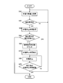
- FIG. 2 is a flowchart of the charge control routine according to the first embodiment.
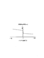
- FIG. 3 is a stop time map.
- FIG. 4 is a time chart when charging control is executed.
- FIG. 5 is a time chart for explaining the effects of the first embodiment.
- FIG. 6 is a flowchart of a charge control routine according to the second embodiment.
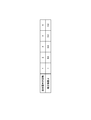
- FIG. 7 is a correction coefficient table for correcting charging stop time.
- FIG. 1 is a configuration diagram of a charging system according to an embodiment of the present invention.
- the charging system includes a battery 3, a charger 2 that supplies charging power to the battery 3, and a controller 1 that controls the charger 2. Furthermore, a current sensor 4 that detects a charging current supplied from the charger 2 to the battery 3, a voltage sensor 5 that detects the battery voltage, and a temperature sensor 6 that detects the temperature of the battery 3 are provided.
- the controller 1 calculates the power charged from the charger 2 to the battery 3 based on the detection values of the current sensor 4 and the voltage sensor 5, and sends a charging power command based on the calculated charging power to the charger 2. Also, the detection value of the temperature sensor 6 is read.
- the internal configuration of the controller 1 will be described later.
- the charger 2 supplies the battery 3 with charging power based on the charging power command from the controller 1.
- the battery 3 is a secondary battery such as a lithium ion battery used as a power source for driving a drive motor of an electric vehicle, for example, and is charged by charging power supplied from the charger 2.
- Detected values of the current sensor 4, voltage sensor 5, and temperature sensor 6 are read into the controller 1.
- the controller 1 includes a chargeable power calculation unit 11, a charge power command unit 10, a timer 12, and a stop time setting unit 13.
- the chargeable power calculation unit 11 reads the detection values of the current sensor 4 and the voltage sensor 5 and calculates chargeable power based on these values.
- the chargeable power means power that can charge the battery 3 until the battery 3 is fully charged.
- the charge power command unit 10 sends a charge power command based on the chargeable power calculated by the chargeable power calculation unit 11 to the charger 2.
- the charge power command unit 10 determines that the battery is fully charged when the chargeable power calculated by the chargeable power calculation unit 11 is equal to or lower than a predetermined power set in advance, and stops charging. Set the power command to zero [kW]. Furthermore, when it is determined that the battery is fully charged, a command for setting the charging stop time to the stop time setting unit 13 (hereinafter referred to as a stop time setting command) is sent.
- a stop time setting command is sent, a count value of a timer 12 to be described later is read. When the count value becomes zero, sending of a charge power command based on chargeable power to the charger 2 is resumed, so-called additional charging. To do.
- the stop time setting unit 13 When the stop time setting unit 13 receives a stop time setting command from the charging power command unit 10, the stop time setting unit 13 calculates a stop time according to the battery temperature and sets the calculated stop time in the timer 12. Although details will be described later, the stop time corresponding to the battery temperature is longer as the battery temperature is lower.
- the timer 12 starts counting down (a process for decreasing the count value every predetermined time). However, the minimum count value is zero.
- FIG. 2 is a flowchart of a charging control routine executed by the controller 1.
- step S10 the controller 1 calculates chargeable power. More specifically, the chargeable power calculation unit 11 calculates chargeable power based on the detection value of the current sensor 4 and the detection value of the voltage sensor 5, and sends this chargeable power to the charge power command unit 10 for charging. The power command unit 10 sends a charge power command to the charger 2.
- a deviation between a predetermined full charge voltage and a detection value of the voltage sensor 5, that is, a voltage increase margin ⁇ V until the full charge state is calculated.
- the current increase allowance ⁇ I until the fully charged state is calculated using the voltage increase allowance ⁇ V and the resistance R of the battery 3 measured in advance. Then, it is possible to calculate a power increase allowance from the voltage increase allowance ⁇ V and the current increase allowance ⁇ I to the fully charged state, that is, chargeable power.
- step S20 the controller 1 determines whether or not the charging power command unit 10 is in a fully charged state. Specifically, when the chargeable power becomes equal to or lower than a predetermined power, it is determined that the battery is fully charged (hereinafter, this determination is referred to as “full charge determination”).
- the predetermined power may be set to zero [kW] for the purpose of determination in this step, but the chargeable power does not decrease to zero due to the detection error of each sensor 4, 5 and the like in a fully charged state. There is a risk that it will not be determined. Therefore, a value close to zero [kW] is set so that it can be determined that the sensor is fully charged even if there is an error in each of the sensors 4 and 5.
- step S30 is executed. If the full charge is not determined, the process of step S10 is executed again.
- the full charge determination is merely a determination that the chargeable power is equal to or lower than the predetermined power, and is not a determination that the battery 3 is actually in a fully charged state.
- step S30 the controller 1 sets the charge stop time after the full charge determination in the stop time setting unit 13.
- the stop time setting unit 13 reads the detection value of the temperature sensor 6, determines the stop time by referring to a previously stored stop time map, sets the determined set time in the timer 12, and sets the timer 12 Start the countdown.
- a longer stop time is set as the battery temperature decreases. This is based on the characteristic that the lower the battery temperature, the longer the time until polarization is eliminated. For example, in the case of a lithium ion battery, the polarization is caused by a concentration difference caused by diffusion of lithium ions as a diffusing material. The lower the battery temperature, the higher the viscosity of the electrolyte solution, and it takes time to eliminate the concentration difference. Therefore, by setting the charging time longer as the battery temperature is lower, polarization is sufficiently eliminated before charging is resumed.
- the stop time map is not limited to FIG. 3 as long as the condition that the longer stop time is set as the battery temperature is lower is satisfied.
- the temperature region may be divided into a plurality of sections and a stop time may be set for each section.
- step S40 the controller 1 refers to the value of the full charge determination number counter provided in the charging power command unit 10, and determines whether or not the full charge determination number is equal to or greater than a predetermined number of times.
- the specified number of times can be set arbitrarily, but is set to about 5 times, for example. If it is less than the specified number of times, the process of step S50 is executed.
- step S50 the controller 1 increments the value of the full charge determination number counter.
- the full charge determination number counter increments the counter value every time the full charge determination is made in step S20 until it is determined in step S40 that the counter value is not less than the specified number.
- step S60 the controller 1 transmits the charging power command value to zero [kW] at the charging power command unit 10 to the charger 2 to stop charging.
- step S70 the controller 1 determines whether or not the charging stop time has elapsed in the charging power command unit 10. Specifically, it is determined whether or not the counter value of the timer 12 has become zero. If the charging stop time has elapsed, the process of step S10 is executed again for additional charging, and if the charging stop time has not elapsed, the process of step S60 is executed again.
- FIG. 4 is a time chart when the above charging control is executed.
- the chargeable power is a constant value until timing T1. This is because a larger chargeable power is calculated in the calculation but is limited by P1, which is the upper limit of the supply capability of the charger 2.
- the chargeable power starts to decrease from the timing T1 when the battery voltage approaches the full charge voltage, and the full charge determination is made at the timing T2 when the battery voltage becomes equal to or less than P2, which is a predetermined value set for determining whether or not the battery is fully charged. Charging stops temporarily. Then, additional charging is started from timing T3 after the charging stop time has elapsed. Thereafter, the charging is repeatedly stopped and restarted until the full charge determination reaches the specified number of times.
- FIG. 5 is a time chart of the amount of power charged in the battery 3.
- the solid line in the figure shows the case where the charging control of this embodiment is executed.
- the case where the charging stop time is constant regardless of the battery temperature is indicated by a broken line.
- the battery temperature is, for example, near zero [° C.].
- the power amount increases in the same manner as in the present embodiment and the comparative example, and the charging is stopped.
- the charging stop time is set according to the battery temperature
- the charging is restarted at timing T3
- follow-up charging is performed at timing T2 earlier than timing T3. Has started.
- the charge stop time is set such that the polarization can be sufficiently eliminated according to the battery temperature, whereas in the comparative example, the charge stop time is constant regardless of the battery temperature, so the polarization is sufficiently eliminated. This is because charging is resumed in a state in which it is not performed. The same trend continues after the second full charge determination.
- a temperature sensor 6 that detects the temperature of the battery 3 and a stop time setting unit 13 that sets a charge stop time based on at least the battery temperature when the full charge determination is made are provided.
- the charging stop time is longer, and the amount of power charged by additional charging is increased, so that charging can be performed efficiently.
- ⁇ Charging is terminated when the number of full charge determinations reaches a preset specified number, so additional charging is not repeated in vain.
- the charging system of the second embodiment is similar to the first embodiment in that the charging system stops charging after full charge determination and performs additional charging when the charging stop time set based on the battery temperature has elapsed. It differs from the first embodiment in that the charging stop time is corrected based on the number of times of determination.
- FIG. 6 is a flowchart showing an example of a charge control routine performed by the controller 1 in the second embodiment.
- the difference from the flowchart of FIG. 2 is that after the number of full charge determinations is counted in step S50, a part for executing step S55 for correcting the charge stop time according to the number of charge determinations, and the charge stop after correction in step S75. This is a part for determining whether or not time has elapsed.
- step S55 the controller 1 corrects the charging stop time set in step S30 to be shorter as the number of full charge determinations increases. Specifically, as in the first embodiment, the charging stop time set in step S30 is multiplied by a correction coefficient ⁇ of 1 or less that decreases as the full charge determination count increases.
- the correction coefficient ⁇ is determined based on the value of the full charge determination number counter with reference to a table shown in FIG.
- the relationship between the number of full charge determinations in the table of FIG. 7 and the correction coefficient ⁇ is set based on the degree of elimination of polarization after the charge is stopped by an experiment or the like.
- the correction coefficient ⁇ does not change and is a fixed value.
- Step S75 is the same as Step S70 in that it is determined whether or not the charging stop time has elapsed based on whether or not the counter value of the timer 12 has become zero. However, the count value at the start of the countdown is different.
- the secondary battery can be charged more efficiently than in the first embodiment.
- the charge stop time at the time when the full charge determination count reaches the predetermined count is maintained thereafter, so that the fixed charge time is not shortened more than necessary, and is followed up. Charging can be performed.
- the charging method and the full charge determination method are not limited to the above-described embodiment.
- a charge current command based on the chargeable power calculated by the chargeable power calculation unit 11 may be output.
- the charge power command unit 10 sends a value obtained by dividing the chargeable power calculated by the chargeable power calculation unit 11 by the battery voltage as a charge current command is conceivable.
- a charge voltage command based on the chargeable power calculated by the chargeable power calculation unit 11 may be output.
- the chargeable power calculation unit 11 calculates chargeable power based on a predetermined full charge voltage and a battery voltage that are determined in advance, and a predetermined constant full charge voltage until the chargeable power becomes a predetermined value or less. Can be considered as a charging voltage command.
- the chargeable power calculated by the chargeable power calculation unit may be determined to be fully charged when the chargeable power is equal to or less than a predetermined value, and the charge command may be set to zero [kW].
- the rechargeable power calculation unit 11 is configured when the battery voltage becomes a predetermined full charge voltage, or when the deviation between the battery voltage and the predetermined full charge voltage becomes a predetermined value or less. It may be determined that the battery is fully charged.
- the charging system of the present invention is not limited with respect to the charging method and the full charge determination method, and is charged until the battery 3 is in a fully charged state, and the charging is stopped for a predetermined time after becoming fully charged. Any configuration can be used.
Landscapes
- Engineering & Computer Science (AREA)
- Power Engineering (AREA)
- Manufacturing & Machinery (AREA)
- Chemical & Material Sciences (AREA)
- Chemical Kinetics & Catalysis (AREA)
- Electrochemistry (AREA)
- General Chemical & Material Sciences (AREA)
- Physics & Mathematics (AREA)
- General Physics & Mathematics (AREA)
- Charge And Discharge Circuits For Batteries Or The Like (AREA)
- Secondary Cells (AREA)
Abstract
La présente invention est équipée : d'une source d'énergie électrique de charge pour fournir de l'énergie électrique à une batterie secondaire ; d'un moyen de détection d'énergie électrique de charge pour détecter l'énergie électrique fournie à la batterie secondaire ; d'un moyen de détermination de charge complète pour déterminer que la batterie secondaire est complètement chargée en fonction de la valeur de détection à partir du moyen de détection d'énergie électrique de charge ; et d'un moyen de commande de charge pour commander la charge afin de charger jusqu'à ce qu'il soit déterminé que la batterie est complètement chargée, pour arrêter de charger une fois qu'il est déterminé que la batterie est complètement chargée, pour recommencer de charger après qu'une période prédéterminée s'est écoulée depuis que la charge s'est arrêtée, et pour continuer de charger jusqu'à ce qu'il soit déterminé que la batterie est complètement chargée à nouveau. En outre, la présente invention est équipée d'un moyen de détection de température pour détecter la température de la batterie secondaire, et d'un moyen de réglage d'intervalle d'arrêt pour régler l'intervalle d'arrêt en fonction de la température de la batterie secondaire au moins lorsqu'il est déterminé que la batterie est complètement chargée. Le moyen de réglage d'intervalle d'arrêt règle un intervalle d'arrêt plus long pour des températures de détection plus basses à partir du moyen de détection de température.
Priority Applications (3)
| Application Number | Priority Date | Filing Date | Title |
|---|---|---|---|
| US14/384,030 US9525299B2 (en) | 2012-03-13 | 2013-03-08 | Charging device for storage battery, and charging method for storage battery |
| EP13761794.0A EP2827470B1 (fr) | 2012-03-13 | 2013-03-08 | Dispositif de charge pour batterie secondaire, et procédé de charge pour batterie secondaire |
| CN201380014148.4A CN104170207B (zh) | 2012-03-13 | 2013-03-08 | 二次电池的充电装置以及二次电池的充电方法 |
Applications Claiming Priority (2)
| Application Number | Priority Date | Filing Date | Title |
|---|---|---|---|
| JP2012-056291 | 2012-03-13 | ||
| JP2012056291A JP5867195B2 (ja) | 2012-03-13 | 2012-03-13 | 二次電池の充電装置および二次電池の充電方法 |
Publications (1)
| Publication Number | Publication Date |
|---|---|
| WO2013137142A1 true WO2013137142A1 (fr) | 2013-09-19 |
Family
ID=49161052
Family Applications (1)
| Application Number | Title | Priority Date | Filing Date |
|---|---|---|---|
| PCT/JP2013/056464 Ceased WO2013137142A1 (fr) | 2012-03-13 | 2013-03-08 | Dispositif de charge pour batterie secondaire, et procédé de charge pour batterie secondaire |
Country Status (5)
| Country | Link |
|---|---|
| US (1) | US9525299B2 (fr) |
| EP (1) | EP2827470B1 (fr) |
| JP (1) | JP5867195B2 (fr) |
| CN (1) | CN104170207B (fr) |
| WO (1) | WO2013137142A1 (fr) |
Cited By (2)
| Publication number | Priority date | Publication date | Assignee | Title |
|---|---|---|---|---|
| JP2015008080A (ja) * | 2013-06-25 | 2015-01-15 | 株式会社マキタ | バッテリパック |
| CN106797126A (zh) * | 2014-08-29 | 2017-05-31 | 日产自动车株式会社 | 二次电池充电系统和充电方法 |
Families Citing this family (9)
| Publication number | Priority date | Publication date | Assignee | Title |
|---|---|---|---|---|
| JP5867195B2 (ja) | 2012-03-13 | 2016-02-24 | 日産自動車株式会社 | 二次電池の充電装置および二次電池の充電方法 |
| US9641009B2 (en) * | 2012-08-20 | 2017-05-02 | Nissan Motor Co., Ltd. | Charging device for secondary battery and charging method for secondary battery |
| US9846200B2 (en) * | 2012-09-26 | 2017-12-19 | Sanyo Electric Co., Ltd. | Battery state estimation device and storage battery system |
| TWI552482B (zh) * | 2015-01-23 | 2016-10-01 | 華碩電腦股份有限公司 | 充電方法及應用其之可攜式電子裝置 |
| CN105515132A (zh) * | 2016-02-17 | 2016-04-20 | 重庆长安汽车股份有限公司 | 一种充电设备 |
| JP6308232B2 (ja) * | 2016-02-26 | 2018-04-11 | トヨタ自動車株式会社 | 二次電池システム |
| EP3698659B1 (fr) * | 2017-10-18 | 2023-04-05 | Japan Tobacco Inc. | Unité de batterie, inhalateur d'arôme, procédé de commande d'unité de batterie, et programme |
| CN115333175A (zh) * | 2021-05-11 | 2022-11-11 | 鸿富锦精密电子(郑州)有限公司 | 充电状态检测方法、充电装置及存储介质 |
| JP7469546B1 (ja) | 2023-08-22 | 2024-04-16 | 東京瓦斯株式会社 | 充電制御システム、充電制御方法、及びプログラム |
Citations (4)
| Publication number | Priority date | Publication date | Assignee | Title |
|---|---|---|---|---|
| JPH10145979A (ja) * | 1996-11-07 | 1998-05-29 | Nissan Motor Co Ltd | リチウムイオン電池の充電方法 |
| JP2005124340A (ja) | 2003-10-17 | 2005-05-12 | Shin Sangyo Souzou Kenkyu Kiko | 二次電池の充電装置 |
| JP2005312239A (ja) * | 2004-04-23 | 2005-11-04 | Sony Corp | 二次電池の充電方法および電池パック |
| JP2007143214A (ja) * | 2005-11-15 | 2007-06-07 | Toyota Motor Corp | 二次電池の制御装置 |
Family Cites Families (19)
| Publication number | Priority date | Publication date | Assignee | Title |
|---|---|---|---|---|
| JP3220803B2 (ja) * | 1991-09-13 | 2001-10-22 | 日立マクセル株式会社 | 二次電池の充電方法 |
| JP2928431B2 (ja) * | 1993-01-13 | 1999-08-03 | 富士通株式会社 | 補助バッテリ装置および充放電制御方法 |
| JPH07312230A (ja) | 1994-05-13 | 1995-11-28 | Toshiba Battery Co Ltd | 二次電池の充電装置 |
| JP2000150000A (ja) * | 1997-12-03 | 2000-05-30 | Matsushita Electric Ind Co Ltd | バックアップ電源の管理方法 |
| EP0921620B1 (fr) | 1997-12-03 | 2005-07-20 | Matsushita Electric Industrial Co., Ltd. | Méthode pour charger, en fonction de la température, une source de puissance de veille qui est soumise à une autodécharge. |
| JP3390668B2 (ja) * | 1998-06-09 | 2003-03-24 | 株式会社マキタ | 充電装置 |
| JP2002303658A (ja) * | 2001-04-03 | 2002-10-18 | Yazaki Corp | バッテリの充電容量状態検出用補正係数算出方法及びその装置 |
| JP3693000B2 (ja) * | 2001-10-30 | 2005-09-07 | 松下電器産業株式会社 | 2次電池の充電制御方法およびそれを用いた電気機器 |
| JP2003324857A (ja) * | 2002-04-26 | 2003-11-14 | Sanyo Electric Co Ltd | バッテリの充電装置 |
| US6937947B2 (en) * | 2002-08-20 | 2005-08-30 | Lsi Logic Corporation | Battery charger system and method for providing detailed battery status and charging method information |
| US7382110B2 (en) | 2004-04-23 | 2008-06-03 | Sony Corporation | Method of charging secondary battery, method of calculating remaining capacity rate of secondary battery, and battery pack |
| JP4514143B2 (ja) * | 2005-03-31 | 2010-07-28 | 本田技研工業株式会社 | 電源装置およびその制御方法 |
| JP2008204810A (ja) * | 2007-02-20 | 2008-09-04 | Toshiba Corp | 非水電解質二次電池の充電方法および充電装置 |
| JP2009017703A (ja) * | 2007-07-05 | 2009-01-22 | Mitsumi Electric Co Ltd | 二次電池の充電制御回路及びこれを用いた充電制御装置 |
| CN101252285B (zh) * | 2008-04-01 | 2010-06-02 | 朴有植 | 稳定车载蓄电池充放电效率的控制装置 |
| CN101834324A (zh) | 2009-03-11 | 2010-09-15 | 孙万平 | 加温式延寿蓄电池 |
| CN102468656B (zh) * | 2010-11-04 | 2014-07-16 | 凹凸电子(武汉)有限公司 | 充电控制装置、方法以及电池管理系统 |
| JP5867195B2 (ja) | 2012-03-13 | 2016-02-24 | 日産自動車株式会社 | 二次電池の充電装置および二次電池の充電方法 |
| US9641009B2 (en) | 2012-08-20 | 2017-05-02 | Nissan Motor Co., Ltd. | Charging device for secondary battery and charging method for secondary battery |
-
2012
- 2012-03-13 JP JP2012056291A patent/JP5867195B2/ja not_active Expired - Fee Related
-
2013
- 2013-03-08 US US14/384,030 patent/US9525299B2/en not_active Expired - Fee Related
- 2013-03-08 EP EP13761794.0A patent/EP2827470B1/fr not_active Not-in-force
- 2013-03-08 WO PCT/JP2013/056464 patent/WO2013137142A1/fr not_active Ceased
- 2013-03-08 CN CN201380014148.4A patent/CN104170207B/zh not_active Expired - Fee Related
Patent Citations (4)
| Publication number | Priority date | Publication date | Assignee | Title |
|---|---|---|---|---|
| JPH10145979A (ja) * | 1996-11-07 | 1998-05-29 | Nissan Motor Co Ltd | リチウムイオン電池の充電方法 |
| JP2005124340A (ja) | 2003-10-17 | 2005-05-12 | Shin Sangyo Souzou Kenkyu Kiko | 二次電池の充電装置 |
| JP2005312239A (ja) * | 2004-04-23 | 2005-11-04 | Sony Corp | 二次電池の充電方法および電池パック |
| JP2007143214A (ja) * | 2005-11-15 | 2007-06-07 | Toyota Motor Corp | 二次電池の制御装置 |
Non-Patent Citations (1)
| Title |
|---|
| See also references of EP2827470A4 |
Cited By (5)
| Publication number | Priority date | Publication date | Assignee | Title |
|---|---|---|---|---|
| JP2015008080A (ja) * | 2013-06-25 | 2015-01-15 | 株式会社マキタ | バッテリパック |
| CN106797126A (zh) * | 2014-08-29 | 2017-05-31 | 日产自动车株式会社 | 二次电池充电系统和充电方法 |
| EP3188340A4 (fr) * | 2014-08-29 | 2017-10-11 | Nissan Motor Co., Ltd | Système et procédé de charge de batterie rechargeable |
| US10286789B2 (en) | 2014-08-29 | 2019-05-14 | Nissan Motor Co., Ltd. | Secondary battery charging system with allowable voltage zone and method thereof |
| CN106797126B (zh) * | 2014-08-29 | 2020-04-24 | 日产自动车株式会社 | 二次电池充电系统和充电方法 |
Also Published As
| Publication number | Publication date |
|---|---|
| CN104170207A (zh) | 2014-11-26 |
| CN104170207B (zh) | 2016-10-12 |
| US20150054449A1 (en) | 2015-02-26 |
| JP5867195B2 (ja) | 2016-02-24 |
| EP2827470A4 (fr) | 2015-04-29 |
| JP2013192348A (ja) | 2013-09-26 |
| EP2827470A1 (fr) | 2015-01-21 |
| US9525299B2 (en) | 2016-12-20 |
| EP2827470B1 (fr) | 2017-07-19 |
Similar Documents
| Publication | Publication Date | Title |
|---|---|---|
| JP5867195B2 (ja) | 二次電池の充電装置および二次電池の充電方法 | |
| JP5967204B2 (ja) | 二次電池の充電装置および二次電池の充電方法 | |
| CN106030893B (zh) | 蓄电系统 | |
| JP5782803B2 (ja) | 電池の充電装置および電池の充電方法 | |
| KR101971324B1 (ko) | 배터리 시스템 | |
| JP5525862B2 (ja) | 充電装置、プログラム | |
| US10220720B2 (en) | Power supply system for vehicle | |
| KR20200069416A (ko) | 친환경 차량의 보조 배터리 보충전 시스템 및 방법 | |
| KR101628507B1 (ko) | 연료전지 차량의 시동 제어방법 | |
| CN112350417B (zh) | 一种电机的电压控制方法及装置 | |
| KR101484241B1 (ko) | 차량용 배터리 관리 장치 | |
| KR20200075929A (ko) | 차량 배터리의 주기적 보충전 방법 | |
| JP2013123360A (ja) | 駆動モーターを備えた車両の電流センサー再設定方法 | |
| JP6434798B2 (ja) | 電力供給ユニット | |
| JP6690584B2 (ja) | 電池状態推定装置 | |
| WO2013008396A1 (fr) | Batterie d'accumulateurs, système de commande du chargement et procédé de chargement | |
| JP5562195B2 (ja) | 充電制御装置 | |
| JP7314805B2 (ja) | 温度推定装置 | |
| WO2022009669A1 (fr) | Dispositif de commande de batterie de stockage | |
| JP7172969B2 (ja) | 充電システム | |
| JP2000023384A (ja) | 充電装置 | |
| JP7655169B2 (ja) | 充電制御装置 | |
| JP2013238536A (ja) | バッテリ残存容量演算装置 | |
| JP7051488B2 (ja) | 監視システムおよび監視方法 | |
| JP2019051045A (ja) | 電気掃除機 |
Legal Events
| Date | Code | Title | Description |
|---|---|---|---|
| 121 | Ep: the epo has been informed by wipo that ep was designated in this application |
Ref document number: 13761794 Country of ref document: EP Kind code of ref document: A1 |
|
| WWE | Wipo information: entry into national phase |
Ref document number: 14384030 Country of ref document: US |
|
| NENP | Non-entry into the national phase |
Ref country code: DE |
|
| REEP | Request for entry into the european phase |
Ref document number: 2013761794 Country of ref document: EP |
|
| WWE | Wipo information: entry into national phase |
Ref document number: 2013761794 Country of ref document: EP |