WO2013137408A1 - 2,3,3,3-テトラフルオロプロペンの製造方法 - Google Patents
2,3,3,3-テトラフルオロプロペンの製造方法 Download PDFInfo
- Publication number
- WO2013137408A1 WO2013137408A1 PCT/JP2013/057257 JP2013057257W WO2013137408A1 WO 2013137408 A1 WO2013137408 A1 WO 2013137408A1 JP 2013057257 W JP2013057257 W JP 2013057257W WO 2013137408 A1 WO2013137408 A1 WO 2013137408A1
- Authority
- WO
- WIPO (PCT)
- Prior art keywords
- reactor
- tetrafluoropropene
- temperature
- supplied
- producing
- Prior art date
- Legal status (The legal status is an assumption and is not a legal conclusion. Google has not performed a legal analysis and makes no representation as to the accuracy of the status listed.)
- Ceased
Links
Images

Classifications
-
- C—CHEMISTRY; METALLURGY
- C07—ORGANIC CHEMISTRY
- C07C—ACYCLIC OR CARBOCYCLIC COMPOUNDS
- C07C17/00—Preparation of halogenated hydrocarbons
- C07C17/26—Preparation of halogenated hydrocarbons by reactions involving an increase in the number of carbon atoms in the skeleton
- C07C17/263—Preparation of halogenated hydrocarbons by reactions involving an increase in the number of carbon atoms in the skeleton by condensation reactions
- C07C17/269—Preparation of halogenated hydrocarbons by reactions involving an increase in the number of carbon atoms in the skeleton by condensation reactions of only halogenated hydrocarbons
Definitions
- the present invention relates to a method for producing 2,3,3,3-tetrafluoropropene, and in particular, 2,3,3,3-tetrafluoropropene in a single reaction from chlorodifluoromethane and chloromethane as raw materials. It relates to a method of manufacturing.
- HFO-1234yf 2,3,3,3-tetrafluoropropene
- HFC-134a 1,1,1,2-tetrafluoroethane
- 1,1-dichloro-2,2,3,3,3-pentafluoropropane (HCFC-225ca) is dehydrofluorinated with an alkaline aqueous solution in the presence of a phase transfer catalyst.
- a method is known in which 1,1-dichloro-2,3,3,3-tetrafluoropropene (CFO-1214ya) obtained by the above process is used as a synthetic raw material and reduced by hydrogen.
- HFO- is obtained by combining different types of hydrochlorocarbon compounds (for example, chloromethane and chlorodifluoromethane), heating to 845 ⁇ 5 ° C. in the presence of water vapor, and dehydrochlorinating / condensing. It is suggested that fluorine atom-containing olefins such as 1234yf and 1,1-difluoroethylene (VdF) have been produced.
- a mixture of chloromethane and chlorodifluoromethane or tetrafluoroethylene is heated and decomposed in a reactor to a temperature of 700 to 950 ° C. by a normal heating means such as an electric heater.
- a method for obtaining HFO-1234yf has been presented.
- the present invention has been made from the above viewpoint, and uses industrially useful HFO-1234yf in a single reaction involving thermal decomposition, using a raw material that is easy to procure, in a sufficiently controlled state and efficiency.
- the object is to provide an economically advantageous method of producing well.
- the present invention relates to a process for producing 2,3,3,3-tetrafluoropropene (HFO-1234yf) from chlorodifluoromethane (R22) and chloromethane (R40), comprising: (a) 1 mole of R22 A step of premixing R22 and R40 in an amount such that R40 is in a ratio of 0.01 to 3 moles with respect to the above, or supplying them separately to the reactor; and (b) supplying a heat medium to the reactor And (c) producing the HFO-1234yf by bringing the heat medium into contact with the R22 and the R40 in the reactor to produce the HFO-1234yf. provide.
- the production method of the present invention it is possible to efficiently produce industrially useful HFO-1234yf by using R22 and R40, which are easily procured, as raw materials and reacting them as they are without taking out the intermediate product from the reaction system. it can. Therefore, compared with a conventionally known method for producing HFO-1234yf, the cost required for raw materials and production equipment can be greatly reduced.
- the production (reaction) conditions can be easily controlled, and thus quantitative HFO-1234yf can be produced, resulting in great economic merit.
- the proportion of HFO-1234yf in the reaction mixture is relative to VdF, the content of which tends to be high in the reaction mixture. It is economically advantageous in that it can be a certain value or more. Furthermore, it is possible to recycle by-products, which has a great economic effect.
- the present invention provides a method for producing HFO-1234yf by a synthesis reaction involving thermal decomposition in the presence of a heat medium using chlorodifluoromethane (R22) and chloromethane (R40) as raw materials. And this manufacturing method (A) mixing the R40 and the R40 in an amount of 0.01 to 3 mol with respect to 1 mol of the R22 in advance, or separately supplying them to the reactor; (B) supplying a heat medium to the reactor; (C) contacting the heat medium with R22 and R40 in the reactor.
- R22 chlorodifluoromethane
- R40 chloromethane
- the production method of the present invention may be a continuous production method or a batch production method.
- supply of the above ratios of R22 and R40 to the reactor, supply of the heat medium to the reactor, and removal of the reaction mixture containing HFO-1234yf from the reactor are both continuous.
- either the supply of R22 and R40 in the step (a) or the supply of the heat medium in the step (b) may be earlier or at the same time. That is, when one of the raw material and the heat medium is supplied, even if the other is not supplied into the reactor, the component supplied later is retained during the retention of the previously supplied raw material or the heat medium.
- the raw material and the heat medium that are supplied may be in contact with each other for a predetermined time in the reactor.
- the production method of the present invention is preferably a continuous method in terms of production efficiency.
- step (d) The step of taking out the reaction mixture containing HFO-1234yf from the reactor is hereinafter referred to as step (d). Therefore, in the continuous manufacturing method, the steps (a), (b) and (d) are all performed simultaneously.
- the raw materials R22 and R40 produce a mixture containing difluorocarbene (F 2 C :) and R40 by thermal decomposition and dehydrochlorination reaction in the reactor, and these are directly added or 1 It is believed that it is converted to tetrafluoropropene, particularly HFO-1234yf, through more than one species of intermediate.
- the process from the thermal decomposition reaction to the formation reaction of HFO-1234yf is referred to as a synthesis reaction involving thermal decomposition.
- VdF is mainly produced as a by-product as shown in the above formula (1).
- other by-products as described later may be produced in a certain amount, but in formula (1), only VdF, which is the most typical by-product, is described. is doing.
- the method for producing HFO-1234yf of the present invention uses R22 and R40 as raw materials.
- the molar ratio of the supply amount of R40 to the supply amount of R22 supplied to the reactor (the supply molar amount of R22, the R40 / R22 when the supply molar amount of R40 is represented by R22 and R40, respectively) is 0.01 to 3 It is.
- the supply amount of each component of the raw material and the heat medium indicates the supply amount per unit time.
- the molar ratio R40 / R22 is more preferably in the range of 0.1 to 3, and particularly preferably in the range of 0.1 to 1.5.
- the conversion rate of the raw material components can be increased.
- the ratio of HFO-1234yf in the reaction mixture taken out from the reactor can be increased as a relative ratio with VdF.
- the content ratio of HFO-1234yf and VdF in the reaction mixture taken out from the reactor in terms of a molar ratio the molar amount of HFO-1234yf / the molar amount of VdF (hereinafter referred to as “HFO-1234yf / VdF”).
- the molar ratio HFO-1234yf / VdF is preferably 0.17 or more, more preferably 0.20 or more. If the value of the molar ratio HFO-1234yf / VdF is 0.14 or more, it can be said that there is an economical advantage as a method for producing HFO-1234yf.
- fluorine-containing compounds other than R22
- fluorine-containing compounds that can be thermally decomposed in a reactor to generate F 2 C :, for example, VdF, tetrafluoroethylene (TFE), hexafluoropropene ( HFP), octafluorocyclobutane (RC318), chlorotrifluoroethylene (CTFE), trifluoroethylene, hexafluoropropylene oxide (HFPO)
- a fluorine-containing compound that can be further thermally decomposed in such a reactor to generate F 2 C: is used as a raw material component
- a newly prepared fluorine-containing compound may be used.
- VdF fluorine-containing compounds by-produced in the accompanying synthesis reaction
- TFE tetrachloride
- HFP tetrachloride
- RC3108 CTFE
- trifluoroethylene trifluoroethylene and the like.
- the reaction mixture taken out from the outlet of the reactor contains unreacted raw material components, reaction products, by-products, heat medium, and the like. From these, the heat medium and the target product HFO-1234yf are separated, and further, by-products other than VdF and the like are removed, whereby a mixture mainly composed of unreacted raw materials R22 and R40, VdF and the like is obtained. can get. By supplying this mixture to the reactor together with new R22 and R40, VdF and the like can be recycled, which is economically advantageous.
- Each raw material component may be introduced into the reactor at room temperature, but in order to improve the reactivity in the reactor, the temperature at the time of introduction into the reactor may be adjusted by heating or the like. However, since the temperature range suitable for improving reactivity is different between the fluorine-containing compound capable of generating F 2 C: such as R22 and R40, it is preferable to perform temperature adjustment separately.
- the temperature of R22 supplied to the reactor and the temperature of VdF and the like supplied to the reactor are preferably 0 to 600 ° C. from the viewpoint that the reactivity is somewhat high, but the carbonization is difficult. From the viewpoint of increasing the reactivity, it is preferable to heat R22, VdF, and the like to normal temperature (25 ° C.) or higher and 600 ° C. or lower, and more preferable to heat to 100 to 500 ° C. before introducing them into the reactor. .
- the temperature of R40 supplied to the reactor is preferably 0 to 1200 ° C. from the viewpoint of reactivity.
- the temperature of each raw material component supplied to the reactor is set to be equal to or lower than the temperature in the reactor in the step (c) described below.
- the raw material components such as R22 and R40 and VdF used as necessary may be supplied to the reactor separately or may be supplied after mixing the respective components.
- the raw material components are divided into groups, for example, R22 and VdF, etc. and the others, and each component is mixed and supplied separately to the reactor in each group. Alternatively, all raw material components may be mixed and then supplied.
- R22 and VdF used as necessary are mixed, adjusted to the above preferable temperature conditions, supplied to the reactor, and separately, R40 is adjusted to the above preferable temperature conditions. It is preferable to supply to the reactor.
- the temperature at the time of introduction into the reactor is preferably less than 600 ° C, and particularly preferably less than 500 ° C.
- the heat medium in the present invention is supplied to the reactor so as to be in contact with the raw material for a certain time in the reactor.
- the heat medium is a medium that does not undergo thermal decomposition at the temperature in the reactor, and specifically, a medium that does not undergo thermal decomposition at a temperature of 100 to 1200 ° C. is preferable.
- Examples of the heat medium include one or more gases selected from water vapor, nitrogen, and carbon dioxide, and it is preferable to use a gas that contains 50% by volume or more of water vapor and the balance is nitrogen and / or carbon dioxide.
- the content ratio of water vapor in the heat medium is preferably 50% by volume or more, and the use of a gas consisting essentially of water vapor only (100% by volume) Is particularly preferred.
- the supply amount of the heat medium is preferably 20 to 98% by volume, more preferably 50 to 95% by volume of the total supply amount of the heat medium and the raw material.
- the temperature of the heat medium supplied to the reactor is preferably 100 to 1200 ° C. from the viewpoint of thermal decomposition and reactivity of raw material components. From the viewpoint of further increasing the reactivity of the raw material components, the temperature of the heat medium introduced into the reactor is more preferably 600 to 900 ° C, and particularly preferably 700 to 900 ° C.
- the contact time of the heating medium supplied in this manner with the raw material in the reactor is preferably 0.01 to 10 seconds, and more preferably 0.2 to 3.0 seconds. By setting the contact time to 0.01 to 10 seconds, the formation reaction of HFO-1234yf can sufficiently proceed and the production of by-products can be suppressed.
- the contact time between the heat medium and the raw material corresponds to the residence time of the raw material in the reactor, and can be controlled by adjusting the supply amount (flow rate) of the raw material to the reactor.
- the shape of the reactor is not particularly limited as long as it can withstand the temperature and pressure in the reactor described later, and examples thereof include a cylindrical vertical reactor.
- Examples of the material of the reactor include glass, iron, nickel, or an alloy mainly composed of iron and nickel.
- the temperature in the reactor in the step (c) is a temperature equal to or higher than the temperature of each component constituting the raw material supplied to the reactor, that is, R40, R22 and VdF used as necessary, and is 400 to 1200 ° C.
- the range is 600 to 900 ° C, more preferably 710 to 900 ° C, and most preferably 710 to 830 ° C.
- the temperature in the reactor can be controlled by adjusting the temperature and pressure of the heat medium supplied to the reactor.
- the inside of the reactor can be supplementarily heated with an electric heater or the like so that the temperature in the reactor falls within the most preferable temperature range (710 to 830 ° C.).
- the pressure in the reactor is preferably 0 to 2.0 MPa as gauge pressure, and more preferably in the range of 0 to 0.5 MPa.
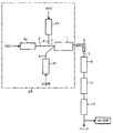
- the reaction apparatus 20 has a reactor 1 provided with heating means such as an electric heater. Connected to the reactor 1 are a supply line 2 of R40 as the first raw material component, a supply line 3 of R22 as the second raw material component, and a supply line 4 of water vapor as a heat medium as shown below. Has been. In addition, installation of the heating means in the reactor 1 is not essential.
- preheaters (preheaters) 2a and 3a each having an electric heater or the like are installed, and after each raw material component to be supplied is preheated to a predetermined temperature. It is supplied to the reactor 1.
- the steam supply line 4 is provided with a superheated steam generator 4a, and the temperature and pressure of the supplied steam are adjusted.
- These supply lines 2, 3, 4 may be connected to the reactor 1 separately, but some or all of the supply lines are connected before the reactor 1 and connected to the reactor 1. Also good.
- the steam supplied to the reactor 1 may be configured to be supplied from the steam supply line 4 to the reactor 1 separately from the raw material mixing supply line 5.
- the R40 supply line 2, the R22 supply line 3, and the water vapor supply line 4 are connected to the reactor 1 separately, and R40, R22 and water vapor are separately supplied to the reactor 1. It can also be configured that these are mixed together in the vicinity of the inlet of the reactor 1.
- An outlet line 7 provided with a cooling means 6 such as a water cooler is connected to the outlet of the reactor 1.
- the outlet line 7 is further provided with a water vapor and acidic liquid recovery tank 8, an alkali cleaning device 9, and a dehydration tower 10 in this order.
- an analyzer such as gas chromatography (GC).
- GC gas chromatography
- the reaction mixture containing HFO-1234yf was taken out from the reactor 1, and the gas obtained by removing acidic substances such as hydrogen chloride, water vapor, water, etc. by the treatment after the outlet line 7 as described above is as follows. It is called outlet gas.
- HFO-1234yf can be obtained as a component of the outlet gas.
- examples of compounds other than HFO-1234yf contained in the outlet gas include methane, ethylene, VdF, TFE, HFP, CTFE, trifluoroethylene, RC318, 1,3,3,3-tetrafluoropropene (HFO-1234ze), 1 , 2-difluoroethylene and the like.
- methane and ethylene having a methylene group ( ⁇ CH 2 ) or a methyl group (—CH 3 ) are compounds derived from the raw material component R40, and VdF, TFE, HFP, having fluorine atoms, CTFE, trifluoroethylene, RC318, HFO-1234ze, and 1,2-difluoroethylene are all compounds derived from the raw material component R22.
- HFO-1234yf and VdF, as well as HFO-1234ze and 1,2-difluoroethylene are compounds derived from R22 as well as compounds derived from R40.
- the above components other than HFO-1234yf contained in the outlet gas can be removed to a desired extent by known means such as distillation.
- the separated VdF, TFE, HFP, CTFE, trifluoroethylene, and RC318 are compounds that can generate F 2 C: and can be recycled as a part of the raw material.
- the obtained VdF, TFE, HFP, CTFE, etc. are PVdF (VdF polymer), PTFE (TFE polymer), FEP (TFE-HFP copolymer), VdF-HFP copolymer, It can also be used as a raw material for fluororesins such as PCTFE (CTFE polymer) and ECTFE (ethylene-CTFE copolymer).
- the production method of the present invention it is possible to efficiently produce HFO-1234yf useful as a new refrigerant having a small global warming potential (GWP) of 4 in one reaction using R22 and R40 as raw materials.
- GWP global warming potential
- the production method of the present invention reduces the cost required for raw materials and production equipment compared to a method that requires a multi-stage reaction in which HFO-1234yf is produced via CFO-1214ya using HCFC-225ca as a raw material.
- the energy required for manufacturing can be greatly reduced.
- the use of a heat medium makes it easy to control production (reaction) conditions, particularly temperature conditions, and thus enables quantitative production of HFO-1234yf.
- reaction reaction
- the proportion of HFO-1234yf in the reaction mixture is relative to VdF, which tends to be high in the reaction mixture.
- the content ratio of HFO-1234yf and VdF in the reaction mixture can be 0.14 or more in terms of molar ratio as HFO-1234yf / VdF.
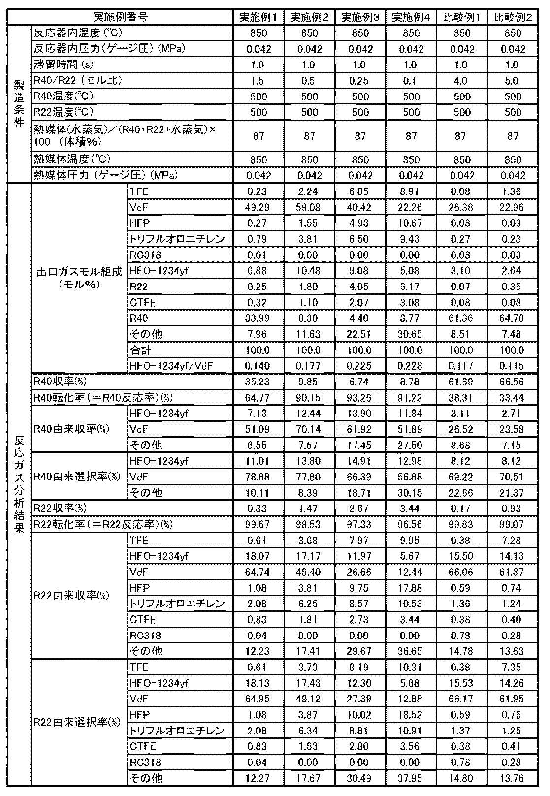
- Example 1 Using the reaction apparatus shown in FIG. 1, crude HFO-1234yf was obtained from a raw material gas composed of R22 and R40 as follows.
- R40 was continuously introduced into the stainless steel tube preheater 2a in the electric furnace set to a furnace temperature of 500 ° C, and R40 was heated to 500 ° C. Further, R22 was continuously introduced into a stainless steel tube preheater 3a in the electric furnace set to a furnace temperature of 500 ° C., and R22 was heated to 500 ° C.
- the flow rate of the source gas (amount supplied per unit time) was controlled so that the residence time of the source gas in the reactor was 1 second, and the gas of the reaction mixture was taken out from the outlet of the reactor.
- the actually measured value of the reactor internal temperature was 850 ° C.
- the actually measured value of the reactor internal pressure was 0.042 MPa.
- the gas of the reaction mixture taken out from the outlet of the reactor includes unreacted source gas in addition to the gas generated or by-produced by the reaction.
- the gas of the reaction mixture taken out from the outlet of the reactor is cooled to 100 ° C. or lower, and after the vapor and acidic liquid are recovered and alkali washed sequentially, dehydration treatment is performed, and the obtained outlet gas is subjected to gas chromatography. Analysis was performed to calculate the molar composition of the gas component contained in the outlet gas. These results are shown in Table 1 together with the reaction conditions.
- the preheat temperature of R40 and R22 is a set temperature in each electric furnace for preheating
- the water vapor temperature is a set temperature in an electric furnace for water vapor heating.
- the water vapor pressure is a set pressure.
- R22 yield Among the R22-derived components (components having fluorine atoms) in the outlet gas, the proportion (mol%) occupied by R22 is mentioned.
- R22 conversion rate reaction rate
- the conversion rate reaction rate
- HFO-1234yf / VdF This is the ratio (molar ratio) of HFO-1234yf to VdF in the outlet gas. It is determined by “mol% of HFO-1234yf in the outlet gas” / “mol% of VdF in the outlet gas”. It represents the ratio (molar ratio) of HFO-1234yf to VdF in the outlet gas.
- Examples 2 to 4 The reaction was carried out under the same conditions as in Example 1 except that the molar ratio of the supply amount of R40 to the supply amount of R22 (R40 / R22) was changed as shown in Table 1. Next, the gas of the reaction mixture taken out from the outlet of the reactor was treated in the same manner as in Example 1, and then the obtained outlet gas was analyzed in the same manner as in Example 1. The results are shown in Table 1 together with the reaction conditions.
- R40 was continuously introduced into a stainless steel tube in an electric furnace set at a furnace temperature of 600 ° C., and R40 was heated to 600 ° C.
- R22 was continuously introduce
- These raw material gas components (R40 and R22) that have been pre-heated and adjusted to the above temperature, and steam (water vapor) heated by an electric furnace set at a furnace temperature of 750 ° C. are used as the molar amount of the raw material components supplied.
- the reactor was fed to a reactor controlled at an internal temperature of 800 ° C.
- the flow rate of the source gas was controlled so that the residence time of the source gas in the reactor was 0.5 seconds, and the gas of the reaction mixture was taken out from the outlet of the reactor.
- the actually measured value of the reactor internal temperature was 800 ° C.
- the actually measured value of the reactor internal pressure was 0.042 MPa.
- the gas of the reaction mixture taken out from the outlet of the reactor was treated in the same manner as in Example 1, and then the obtained outlet gas was analyzed in the same manner as in Example 1. The results are shown in Table 2 together with the reaction conditions.
- Example 6 to 11 The reaction was carried out under the same conditions as in Example 5 except that the molar ratio of the supply amount of R40 to the supply amount of R22 (R40 / R22) was changed as shown in Table 2. Next, the gas of the reaction mixture taken out from the outlet of the reactor was treated in the same manner as in Example 1, and then the obtained outlet gas was analyzed in the same manner as in Example 1. The results are shown in Table 2 together with the reaction conditions.
- Example 3 The reaction was carried out under the same conditions as in Example 5 except that the molar ratio of the supply amount of R40 to the supply amount of R22 (R40 / R22) was changed to 10. Next, the gas of the reaction mixture taken out from the outlet of the reactor was treated in the same manner as in Example 1, and then the obtained outlet gas was analyzed in the same manner as in Example 1. The results are shown in Table 2 together with the reaction conditions.
- Example 12 to 16 The reaction was carried out under the same conditions as in Example 5 except that the raw material gas molar ratio (R40 / R22), residence time, and R40 gas temperature in the reactor were changed as shown in Table 3. Next, the gas of the reaction mixture taken out from the outlet of the reactor was treated in the same manner as in Example 1, and then the obtained outlet gas was analyzed in the same manner as in Example 1. The results are shown in Table 3 together with the reaction conditions.
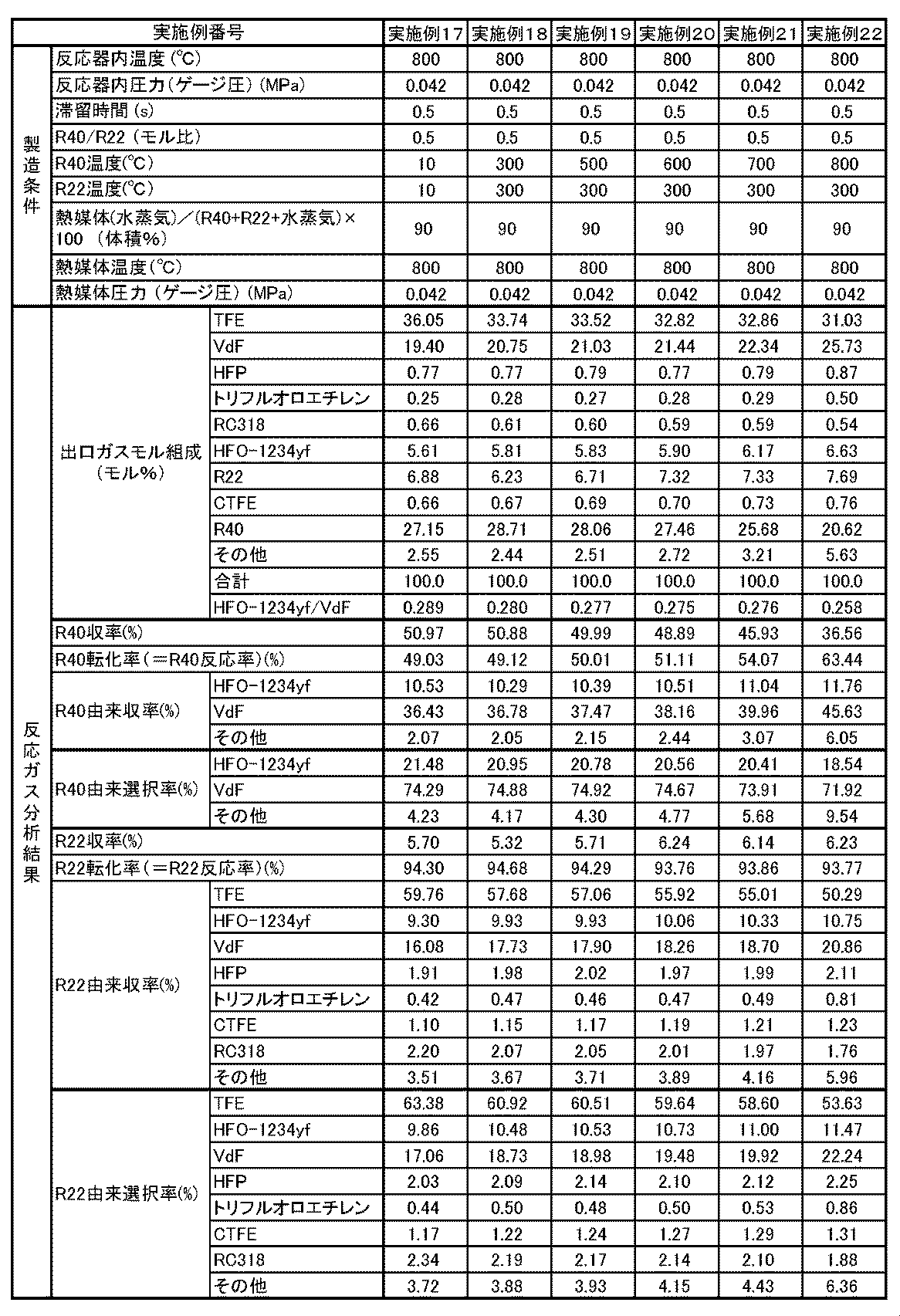
- Example 17 to 22 The reaction was carried out under the same conditions as in Example 5 except that the molar ratio of R40 and R22 (R40 / R22) and the gas temperature were changed as shown in Table 4. Next, the gas of the reaction mixture taken out from the outlet of the reactor was treated in the same manner as in Example 1, and then the obtained outlet gas was analyzed in the same manner as in Example 1. The results are shown in Table 4 together with the reaction conditions.
- Examples 23 to 30 The reaction was carried out under the same conditions as in Example 5 except that the temperature in the reactor, the residence time of the raw material gas, the molar ratio of R40 / R22, and the gas temperature of R40 were changed as shown in Table 5. Next, the gas of the reaction mixture taken out from the outlet of the reactor was treated in the same manner as in Example 1, and then the obtained outlet gas was analyzed in the same manner as in Example 1. The results are shown in Table 5 together with the reaction conditions.
- Examples 31 to 36 The gas temperature of R40, the molar ratio of R40 / R22, and the supply ratio of water vapor to the total gas supply amount (the ratio expressed by the volume ratio of water vapor / (R40 + R22 + water vapor)) were changed as shown in Table 6 in volume%.
- the reaction was carried out under the same conditions as in Example 5 except for the above.
- the gas of the reaction mixture taken out from the outlet of the reactor was treated in the same manner as in Example 1, and then the obtained outlet gas was analyzed in the same manner as in Example 1. The results are shown in Table 6 together with the reaction conditions.
- Examples 37 to 39 The reaction was carried out under the same conditions as in Example 5 except that the gas temperature of R40, the molar ratio of R40 / R22 and the pressure in the reactor were changed as shown in Table 7. Next, the gas of the reaction mixture taken out from the outlet of the reactor was treated in the same manner as in Example 1, and then the obtained outlet gas was analyzed in the same manner as in Example 1. The results are shown in Table 7 together with the reaction conditions.
- HFO-1234yf / VdF in the outlet gas was 0.14 or more, and the selectivity for RFO-derived HFO-1234yf ( %) Is significantly higher than those in Comparative Examples 1 to 3 in which R40 / R22 is outside the scope of the present invention.
- the value of HFO-1234yf / VdF in the outlet gas is 0.17 or more in Examples 2 to 22 and 25 to 39, and further 0.20 or more in Examples 3 to 22 and 25 to 39. From these results, it can be said that according to the production method of the present invention, HFO-1234yf can be obtained efficiently.
- the production method of the present invention it is possible to efficiently produce industrially useful HFO-1234yf by using R22 and R40, which are easily procured, as raw materials and reacting them as they are without taking out the intermediate product from the reaction system. it can. Therefore, compared with a conventionally known method, the cost required for the raw materials and the production equipment can be greatly reduced.
- the production (reaction) conditions can be easily controlled, and thus quantitative HFO-1234yf can be produced, which is economically advantageous.
- the proportion of HFO-1234yf in the reaction mixture is relative to VdF, the content of which tends to be high in the reaction mixture. It is economically advantageous in that it can be a certain value or more.
Landscapes
- Chemical & Material Sciences (AREA)
- Organic Chemistry (AREA)
- Chemical Kinetics & Catalysis (AREA)
- Organic Low-Molecular-Weight Compounds And Preparation Thereof (AREA)
Abstract
調達の容易な原料を使用し、熱分解を伴う1回の反応で、工業的に有用なHFO-1234yfを、十分に制御された状態かつ効率よく製造する経済的に有利な方法を提供する。 クロロジフルオロメタンとクロロメタンを含む原料組成物から、熱分解を伴う合成反応により2,3,3,3-テトラフルオロプロペンを製造する方法であって、(a)前記クロロジフルオロメタンの1モルに対して前記クロロメタンを0.01~3.0モルの割合で両者を予め混合し、または別々に反応器に供給す工程と、(b)熱媒体を前記反応器に供給する工程と、該反応器内でクロロジフルオロメタンとクロロメタンに熱媒体を接触させて2,3,3,3-テトラフルオロプロペンを生成する工程とを有することを特徴とする2,3,3,3-テトラフルオロプロペンの製造方法を提供する。
Description
本発明は、2,3,3,3-テトラフルオロプロペンの製造方法に係り、特に、原料であるクロロジフルオロメタンとクロロメタンから、1回の反応で2,3,3,3-テトラフルオロプロペンを製造する方法に関する。
2,3,3,3-テトラフルオロプロペン(HFO-1234yf)は、温室効果ガスである1,1,1,2-テトラフルオロエタン(HFC-134a)に代わる新しい冷媒として、近年大きな期待が寄せられている。なお、本明細書において、ハロゲン化炭化水素については化合物名の後の括弧内にその化合物の略称を記すが、本明細書では必要に応じて化合物名に代えてその略称を用いる。
HFO-1234yfの製造方法としては、例えば、1,1-ジクロロ-2,2,3,3,3-ペンタフルオロプロパン(HCFC-225ca)を相間移動触媒の存在下にアルカリ水溶液で脱フッ化水素させて得られる1,1-ジクロロ-2,3,3,3-テトラフルオロプロペン(CFO-1214ya)を合成原料とし、水素により還元して製造する方法が知られている。
しかし、このような方法では、多段階の反応を経るため設備コストが高くなる、中間生成物や最終生成物における蒸留・精製が難しい、などの問題がある。
特許文献1には、異なる種類のハイドロクロロ炭素化合物(例えば、クロロメタンとクロロジフルオロメタン)を組み合わせて、水蒸気の共存下に845±5℃に加熱し、脱塩化水素・縮合させることによりHFO-1234yfや1,1-ジフルオロエチレン(VdF)のようなフッ素原子含有オレフィン類が生成したことが提示されている。
また、特許文献2には、クロロメタンと、クロロジフルオロメタンまたはテトラフルオロエチレンとの混合物を、反応器内で電気ヒータのような通常の加熱手段により700~950℃の温度に加熱・分解して、HFO-1234yfを得る方法が提示されている。
また、特許文献2には、クロロメタンと、クロロジフルオロメタンまたはテトラフルオロエチレンとの混合物を、反応器内で電気ヒータのような通常の加熱手段により700~950℃の温度に加熱・分解して、HFO-1234yfを得る方法が提示されている。
しかしながら、特許文献2に示された方法では滞留時間の増加に伴い、副生成物である高沸物の生成・原料のカーボン化が起こり反応器が閉塞するおそれがあり、また副生する酸分の影響から、特殊な耐腐食装置(プラチナでライニングされた反応管等)が必要であり、工業的な製造を考えた場合、全く現実的でない。
特許文献1に記載された方法では、原料成分が十分に反応に供されておらず、たとえば、クロロメタンの転化率は17%と効率的な反応が達成されてはいなかった。また、得られる生成物中のVdFの割合が高く、必ずしもHFO-1234yfを効率よく製造しているとは言い難かった。
特許文献1に記載された方法では、原料成分が十分に反応に供されておらず、たとえば、クロロメタンの転化率は17%と効率的な反応が達成されてはいなかった。また、得られる生成物中のVdFの割合が高く、必ずしもHFO-1234yfを効率よく製造しているとは言い難かった。
本発明は、上記観点からなされたものであり、調達の容易な原料を使用し、熱分解を伴う1回の反応で、工業的に有用なHFO-1234yfを、十分に制御された状態かつ効率よく製造する経済的に有利な方法を提供することを目的とする。
本発明は、クロロジフルオロメタン(R22)とクロロメタン(R40)から、2,3,3,3-テトラフルオロプロペン(HFO-1234yf)を製造する方法であって、(a)前記R22の1モルに対して前記R40が0.01~3モルの割合となる量の前記R22と前記R40とを、予め混合し、または別々に反応器に供給する工程と、(b)熱媒体を前記反応器に供給する工程と、(c)前記反応器内で前記R22および前記R40に前記熱媒体を接触させて前記HFO-1234yfを生成する工程とを有することを特徴とするHFO-1234yfの製造方法を提供する。
本発明の製造方法によれば、調達が容易なR22とR40を原料として、中間生成物を反応系から取り出すことなく、そのまま反応させ、工業的に有用なHFO-1234yfを効率よく製造することができる。したがって、従来公知のHFO-1234yfを製造する方法に比べて、原料および製造設備に要するコストを大幅に低減することができる。
また、本発明の製造方法によれば、製造(反応)条件の制御が容易であり、よって定量的なHFO-1234yfの製造が可能となり経済的なメリットが大きい。具体的には、R22とR40を原料とする熱分解を伴う合成反応において、反応混合物中に占めるHFO-1234yfの割合を、反応混合物においてその含有割合が高くなりがちなVdFとの相対関係において、一定値以上とできる点で経済的に有利である。またさらに、副生物のリサイクルも可能であり、経済的な効果が大きい。
以下に、本発明の実施の形態について説明する。
本発明は、原料として、クロロジフルオロメタン(R22)とクロロメタン(R40)を用い、熱媒体の存在下で、熱分解を伴う合成反応により、HFO-1234yfを製造する方法を提供する。そして、この製造方法は、
(a)前記R22の1モルに対して前記R40を0.01~3モルの割合となる量の前記R22と前記R40とを、予め混合し、または別々に反応器に供給する工程と、
(b)熱媒体を前記反応器に供給する工程と、
(c)前記反応器内で前記R22および前記R40に前記熱媒体を接触させる工程とを有する。
本発明は、原料として、クロロジフルオロメタン(R22)とクロロメタン(R40)を用い、熱媒体の存在下で、熱分解を伴う合成反応により、HFO-1234yfを製造する方法を提供する。そして、この製造方法は、
(a)前記R22の1モルに対して前記R40を0.01~3モルの割合となる量の前記R22と前記R40とを、予め混合し、または別々に反応器に供給する工程と、
(b)熱媒体を前記反応器に供給する工程と、
(c)前記反応器内で前記R22および前記R40に前記熱媒体を接触させる工程とを有する。
本発明の製造方法は、連続式の製造方法であっても、バッチ式の製造方法であってもよい。連続式の製造方法において、上記割合のR22およびR40の反応器への供給と熱媒体の反応器への供給、およびHFO-1234yfを含む反応混合物の前記反応器からの取り出しは、いずれも連続的に行われる。バッチ式の製造では、(a)工程におけるR22とR40の供給と(b)工程における熱媒体の供給とは、どちらが先であっても、あるいは同時であってもよい。すなわち、原料と熱媒体のいずれか一方の供給の際に、反応器内に他方が供給されていない場合でも、先に供給された原料または熱媒体の滞留中に、後から供給される成分が供給され、原料と熱媒体とが反応器内で所定の時間接触すればよい。
本発明の製造方法は、製造効率の点で連続式の方法であるのが好ましい。以下、本発明の方法を連続式の製造に適用する実施形態について説明するが、これに限定されない。
なお、前記反応器からHFO-1234yfを含む反応混合物を取り出す工程を、以下、工程(d)という。したがって、上記連続的な製造方法においては、上記工程(a)、工程(b)および工程(d)はすべて同時に行われる。
本発明の製造方法は、製造効率の点で連続式の方法であるのが好ましい。以下、本発明の方法を連続式の製造に適用する実施形態について説明するが、これに限定されない。
なお、前記反応器からHFO-1234yfを含む反応混合物を取り出す工程を、以下、工程(d)という。したがって、上記連続的な製造方法においては、上記工程(a)、工程(b)および工程(d)はすべて同時に行われる。
<R22およびR40による合成反応>
本発明の製造方法において、反応器内の主な反応を下記式(1)に示す。
本発明の製造方法において、反応器内の主な反応を下記式(1)に示す。

原料であるR22およびR40は、反応器内で熱分解および脱塩化水素反応によりジフルオロカルベン(F2C:)とR40とを含む混合物を生成し、さらにこれらは、直接付加反応して、あるいは1種以上の中間体を経て、テトラフルオロプロペン、特にHFO-1234yfへと転化されると考えられる。本発明においては、これら熱分解反応からHFO-1234yfの生成反応までを、熱分解を伴う合成反応という。
また、反応器内では、上記式(1)に示すとおり副生物として主にVdFが生成する。なお、反応条件によっては、VdF以外にもある程度の量で、後述するような他の副生物が生成する場合があるが、式(1)においては最も典型的な副生物であるVdFのみを記載している。
また、反応器内では、上記式(1)に示すとおり副生物として主にVdFが生成する。なお、反応条件によっては、VdF以外にもある程度の量で、後述するような他の副生物が生成する場合があるが、式(1)においては最も典型的な副生物であるVdFのみを記載している。
<原料>
本発明のHFO-1234yfの製造方法は、R22とR40を原料として用いる。
反応器に供給するR22の供給量に対するR40の供給量のモル比(R22の供給モル量、R40の供給モル量をそれぞれR22、R40で表した場合のR40/R22)は、0.01~3である。なお、原料および熱媒体を、反応器内を連続的に流通させて反応を行わせる本実施形態において、原料各成分および熱媒体の供給量は、単位時間当たりの供給量を示すものとする。なお、モル比R40/R22は、0.1~3の範囲がより好ましく、0.1~1.5の範囲が特に好ましい。
本発明のHFO-1234yfの製造方法は、R22とR40を原料として用いる。
反応器に供給するR22の供給量に対するR40の供給量のモル比(R22の供給モル量、R40の供給モル量をそれぞれR22、R40で表した場合のR40/R22)は、0.01~3である。なお、原料および熱媒体を、反応器内を連続的に流通させて反応を行わせる本実施形態において、原料各成分および熱媒体の供給量は、単位時間当たりの供給量を示すものとする。なお、モル比R40/R22は、0.1~3の範囲がより好ましく、0.1~1.5の範囲が特に好ましい。
モル比R40/R22を上記範囲とすることで、原料成分の転化率、特にR40の転化率を高くすることができる。また、反応器から取り出される反応混合物における、HFO-1234yfの割合をVdFとの相対的な割合として高くすることができる。具体的には、反応器から取り出される反応混合物におけるHFO-1234yfとVdFの含有割合をモル比で、HFO-1234yfのモル量/VdFのモル量(以下、「HFO-1234yf/VdF」と示す)として0.14以上とすることができる。モル比HFO-1234yf/VdFは、好ましくは0.17以上であり、さらに好ましくは0.20以上である。モル比HFO-1234yf/VdFの値が0.14以上であれば、HFO-1234yfの製造方法として経済的に優位性があるといえる。
原料としては、これら2成分に加えて、反応器内で熱分解してF2C:を発生しうる含フッ素化合物(R22以外)、例えば、VdF、テトラフルオロエチレン(TFE)、ヘキサフルオロプロペン(HFP)、オクタフルオロシクロブタン(RC318)、クロロトリフルオロエチレン(CTFE)、トリフルオロエチレン、ヘキサフルオロプロピレンオキサイド(HFPO)を使用することができる。原料成分としてさらにこのような反応器内で熱分解してF2C:を発生しうる含フッ素化合物を用いる場合には、新たに用意した含フッ素化合物を用いてもよいが、前記熱分解を伴う合成反応において副生する含フッ素化合物、例えば、VdF、TFE、HFP、RC318、CTFE、トリフルオロエチレン等から選ばれる1種以上を用いることが、リサイクルの観点から好ましい。
以下、R22以外の、反応器内で熱分解してF2C:を発生しうる含フッ素化合物を、VdF等という。
以下、R22以外の、反応器内で熱分解してF2C:を発生しうる含フッ素化合物を、VdF等という。
本発明の製造方法において、反応器の出口から取り出される反応混合物には未反応原料成分、反応生成物、副生物および熱媒体等が含まれる。これらから、熱媒体および目的生成物であるHFO-1234yfを分離し、さらに、VdF等以外の副生物を除去することで、未反応原料のR22およびR40とVdF等とから主として構成される混合物が得られる。この混合物を、新たなR22とR40とともに反応器に供給することで、VdF等のリサイクルが可能となり、経済的に有利である。
各原料成分は、常温のまま反応器に導入してもよいが、反応器内での反応性を向上させるために、反応器に導入する際の温度を加熱等により調整してもよい。ただし、R22などのF2C:を発生しうる含フッ素化合物とR40とは、反応性を向上させるのに好適な温度範囲が異なるので、温度調整を別々に行うことが好ましい。
反応器に供給するR22の温度、および反応器に供給するVdF等の温度は、反応性がある程度高いが、カーボン化はしにくい温度とするという観点から0~600℃とするのが好ましい。
より反応性を高めるという観点からは、R22およびVdF等を、反応器に導入する前に常温(25℃)以上600℃以下に加熱することが好ましく、100~500℃に加熱することがより好ましい。
また、反応器に供給するR40の温度は、反応性の観点から0~1200℃とするのが好ましい。より反応性を高めるという観点からは、R40を反応器に導入する前に常温以上1200℃以下に加熱することが好ましく、100~800℃に加熱することがより好ましい。
ただし、反応器に供給する上記各原料成分の温度はそれぞれ、以下に説明する工程(c)における反応器内の温度以下に設定される。
より反応性を高めるという観点からは、R22およびVdF等を、反応器に導入する前に常温(25℃)以上600℃以下に加熱することが好ましく、100~500℃に加熱することがより好ましい。
また、反応器に供給するR40の温度は、反応性の観点から0~1200℃とするのが好ましい。より反応性を高めるという観点からは、R40を反応器に導入する前に常温以上1200℃以下に加熱することが好ましく、100~800℃に加熱することがより好ましい。
ただし、反応器に供給する上記各原料成分の温度はそれぞれ、以下に説明する工程(c)における反応器内の温度以下に設定される。
R22およびR40、さらに必要に応じて用いられるVdF等、の各原料成分の反応器への供給は、別々であってもよいし、各成分を混合してから供給してもよい。各成分を混合してから供給する場合には、原料成分をグループに分けて、例えば、R22およびVdF等とそれ以外に分けて、各グループでそれぞれ各成分を混合し反応器に別々に供給してもよいし、全原料成分を混合してから供給してもよい。上記温度条件の違いを考慮すれば、R22および必要に応じて用いられるVdF等を混合し上記好ましい温度条件に調整して反応器に供給し、これとは別にR40を上記好ましい温度条件に調整して反応器に供給することが好ましい。
なお、R22およびR40、さらに必要に応じて用いられるVdF等、の各原料成分を予め混合してから、反応器に供給する場合は、反応器の手前で反応・分解が進行してしまうことを防ぐという観点から、反応器に導入する際の温度は600℃未満にすることが好ましく、特に500℃未満にすることが好ましい。
<熱媒体>
本発明における熱媒体は、前記原料と反応器内で一定の時間接触するように、反応器に供給される。熱媒体は、反応器内の温度で熱分解が生じない媒体であり、具体的には100~1200℃の温度で熱分解しない媒体であるのが好ましい。熱媒体としては、水蒸気、窒素および二酸化炭素から選ばれる1種以上の気体が挙げられ、水蒸気を50体積%以上含み、残部が窒素および/または二酸化炭素である気体の使用が好ましい。上記式(1)の熱分解反応で生成するHClを塩酸にして除くため、熱媒体における水蒸気の含有割合は50体積%以上が好ましく、実質的に水蒸気のみ(100体積%)からなる気体の使用が特に好ましい。
本発明における熱媒体は、前記原料と反応器内で一定の時間接触するように、反応器に供給される。熱媒体は、反応器内の温度で熱分解が生じない媒体であり、具体的には100~1200℃の温度で熱分解しない媒体であるのが好ましい。熱媒体としては、水蒸気、窒素および二酸化炭素から選ばれる1種以上の気体が挙げられ、水蒸気を50体積%以上含み、残部が窒素および/または二酸化炭素である気体の使用が好ましい。上記式(1)の熱分解反応で生成するHClを塩酸にして除くため、熱媒体における水蒸気の含有割合は50体積%以上が好ましく、実質的に水蒸気のみ(100体積%)からなる気体の使用が特に好ましい。
熱媒体の供給量は、熱媒体および原料の供給量の合計の20~98体積%となる割合が好ましく、50~95体積%がより好ましい。熱媒体および原料の供給量の合計に対する熱媒体の供給量の割合を20体積%以上とすることで、高沸物の生成や原料のカーボン化を抑制しながら上記式(1)の熱分解反応を進行させて、HFO-1234yfを効率よく製造できるようになる。また、上記割合が98体積%を超えると、生産性が著しく低下するため、工業的に現実的でない。
また、反応器に供給する熱媒体の温度は、その熱分解と原料成分の反応性の観点から100~1200℃とするのが好ましい。原料成分の反応性をより高めるという観点からは、反応器に導入する熱媒体の温度を600~900℃とすることがより好ましく、700~900℃とするのが特に好ましい。
また、反応器に供給する熱媒体の温度は、その熱分解と原料成分の反応性の観点から100~1200℃とするのが好ましい。原料成分の反応性をより高めるという観点からは、反応器に導入する熱媒体の温度を600~900℃とすることがより好ましく、700~900℃とするのが特に好ましい。
このように供給される熱媒体と上記原料との反応器内での接触時間は、0.01~10秒間とするのが好ましく、0.2~3.0秒間とするのがより好ましい。接触時間を0.01~10秒間とすることで、HFO-1234yfの生成反応を十分に進行させ、かつ副生物の生成を抑えることができる。なお、熱媒体と原料との接触時間は、原料の反応器内での滞留時間に相当し、原料の反応器への供給量(流量)を調節することで制御できる。
<反応器>
反応器としては、後述する反応器内温度および圧力に耐えるものであれば、特に形状は限定されず、例えば円筒状の縦型反応器が挙げられる。反応器の材質としては、ガラス、鉄、ニッケル、または鉄、ニッケルを主成分とする合金等が挙げられる。
反応器としては、後述する反応器内温度および圧力に耐えるものであれば、特に形状は限定されず、例えば円筒状の縦型反応器が挙げられる。反応器の材質としては、ガラス、鉄、ニッケル、または鉄、ニッケルを主成分とする合金等が挙げられる。
工程(c)における反応器内の温度は、反応器に供給される原料を構成する各成分、すなわちR40、R22および必要に応じて用いられるVdF等の温度以上の温度とし、かつ400~1200℃とすることが好ましく、600~900℃の範囲がさらに好ましく、710~900℃の範囲が特に好ましく、710~830℃の範囲が最も好ましい。反応器内の温度を400~1200℃の範囲とすることで、上記式(1)で示される熱分解を伴う生成反応の反応率を高め、HFO-1234yfを効率よく得ることができる。
反応器内の温度は、反応器に供給される前記熱媒体の温度および圧力を調整することで制御することができる。また、前記反応器内の温度が最も好ましい温度範囲(710~830℃)になるように、電気ヒータ等により反応器内を補助的に加熱することもできる。
反応器内の圧力は、ゲージ圧で0~2.0MPaとすることが好ましく、0~0.5MPaの範囲がさらに好ましい。
<反応装置>
本発明において、HFO-1234yfの製造に使用される反応装置の一例を、図1および図2に示す。
反応装置20は、電気ヒータ等の加熱手段を備えた反応器1を有する。反応器1には、第1の原料成分であるR40の供給ライン2、第2の原料成分であるR22の供給ライン3、および熱媒体としての水蒸気の供給ライン4が、以下に示すように接続されている。なお、反応器1における加熱手段の設置は必須ではない。
本発明において、HFO-1234yfの製造に使用される反応装置の一例を、図1および図2に示す。
反応装置20は、電気ヒータ等の加熱手段を備えた反応器1を有する。反応器1には、第1の原料成分であるR40の供給ライン2、第2の原料成分であるR22の供給ライン3、および熱媒体としての水蒸気の供給ライン4が、以下に示すように接続されている。なお、反応器1における加熱手段の設置は必須ではない。
R40の供給ライン2およびR22の供給ライン3には、それぞれ電気ヒータ等を備えた予熱器(プレヒータ)2a、3aが設置されており、供給される各原料成分が所定の温度に予熱されてから反応器1に供給される。また、水蒸気の供給ライン4には、過熱水蒸気発生器4aが設置されており、供給される水蒸気の温度および圧力が調整される。
これらの供給ライン2、3、4はそれぞれ別々に反応器1に接続されていてもよいが、一部または全部の供給ラインは反応器1の手前で連結されて反応器1に接続されていてもよい。
たとえば、図1に示すように、それぞれの予熱器2a、3aを経た後の供給ライン2、3を連結することで、全ての原料成分が混合された原料混合物が、原料混合供給ライン5から反応器1に供給され、水蒸気は、原料混合供給ライン5とは別に、水蒸気供給ライン4から反応器1に供給されるように構成してもよい。
また、図2に示すように、R40の供給ライン2、R22の供給ライン3、水蒸気の供給ライン4はそれぞれ別々に反応器1に接続され、R40、R22および水蒸気が別個に反応器1に供給されて反応器1の入り口付近でこれらが一体に混合されるように構成することもできる。
たとえば、図1に示すように、それぞれの予熱器2a、3aを経た後の供給ライン2、3を連結することで、全ての原料成分が混合された原料混合物が、原料混合供給ライン5から反応器1に供給され、水蒸気は、原料混合供給ライン5とは別に、水蒸気供給ライン4から反応器1に供給されるように構成してもよい。
また、図2に示すように、R40の供給ライン2、R22の供給ライン3、水蒸気の供給ライン4はそれぞれ別々に反応器1に接続され、R40、R22および水蒸気が別個に反応器1に供給されて反応器1の入り口付近でこれらが一体に混合されるように構成することもできる。
反応器1の出口には、水冷器のような冷却手段6が設置された出口ライン7が接続されている。出口ライン7には、さらに、水蒸気および酸性液回収槽8、アルカリ洗浄装置9および脱水塔10が順に設置されている。そして、脱水塔10により脱水された後、得られたガスの各成分がガスクロマトグラフィ(GC)のような分析装置により分析・定量されるようになっている。
なお、HFO-1234yfを含有する反応混合物が反応器1から取り出され、上記のように出口ライン7以降の処理によって塩化水素などの酸性物質、水蒸気、水などが除去されて得られたガスを以下出口ガスという。
なお、HFO-1234yfを含有する反応混合物が反応器1から取り出され、上記のように出口ライン7以降の処理によって塩化水素などの酸性物質、水蒸気、水などが除去されて得られたガスを以下出口ガスという。
<出口ガス成分>
本発明の製造方法においては、HFO-1234yfを上記出口ガスの成分として得ることができる。出口ガスが含有するHFO-1234yf以外の化合物としては、メタン、エチレン、VdF、TFE、HFP、CTFE、トリフルオロエチレン、RC318、1,3,3,3-テトラフルオロプロペン(HFO-1234ze)、1,2-ジフルオロエチレン等が挙げられる。
本発明の製造方法においては、HFO-1234yfを上記出口ガスの成分として得ることができる。出口ガスが含有するHFO-1234yf以外の化合物としては、メタン、エチレン、VdF、TFE、HFP、CTFE、トリフルオロエチレン、RC318、1,3,3,3-テトラフルオロプロペン(HFO-1234ze)、1,2-ジフルオロエチレン等が挙げられる。
これらの成分のうちで、メチレン基(=CH2)またはメチル基(-CH3)を有するメタンおよびエチレンは、原料成分のR40に由来する化合物であり、フッ素原子を有するVdF、TFE、HFP、CTFE、トリフルオロエチレン、RC318、HFO-1234ze、1,2-ジフルオロエチレンは、いずれも原料成分のR22に由来する化合物である。なお、HFO-1234yfおよびVdF、さらにHFO-1234ze、1,2-ジフルオロエチレンは、R22に由来する化合物であるとともに、R40に由来する化合物でもある。
出口ガスに含まれるHFO-1234yf以外の上記成分は、蒸留等の既知の手段により、望まれる程度に除去することができる。そして、分離されたVdF、TFE、HFP、CTFE、トリフルオロエチレン、およびRC318は、F2C:を発生し得る化合物であり、原料の一部としてリサイクルが可能である。なお、得られるVdF、TFE、HFP、CTFE等は、必要に応じて、PVdF(VdF重合体)、PTFE(TFE重合体)、FEP(TFE-HFP共重合体)、VdF-HFP共重合体、PCTFE(CTFE重合体)、ECTFE(エチレン-CTFE共重合体)等のフッ素樹脂の原料として使用することもできる。
本発明の製造方法によれば、R22とR40を原料として、1回の反応で、地球温暖化係数(GWP)が4と小さい、新冷媒として有用なHFO-1234yfを効率よく製造することができる。例えば、本発明の製造方法は、HCFC-225caを原料としてCFO-1214yaを経由してHFO-1234yfを製造する多段階反応が必要な方法に比べて、原料および製造設備に要するコストを低減することができるばかりでなく、製造に必要なエネルギーを圧倒的に低減することができる。
また、本発明の製造方法によれば、熱媒体を用いることで、製造(反応)条件の制御、特に温度条件の制御が容易であり、よって定量的なHFO-1234yfの製造が可能となり経済的なメリットが大きい。具体的には、R22とR40を原料とする熱分解を伴う合成反応において、反応混合物中に占めるHFO-1234yfの割合を、反応混合物においてその含有割合が高くなりがちなVdFとの相対関係において、一定値以上、例えば、反応混合物におけるHFO-1234yfとVdFの含有割合をモル比で、HFO-1234yf/VdFとして0.14以上、とすることができる点で経済的に有利である。またさらに、F2C:を発生し得る副生物をリサイクルして原料成分として使用することも可能であり、経済的な効果が大きい。
以下に、本発明を実施例によって具体的に説明するが、本発明はこれらの実施例によって限定されるものではない。
[実施例1]
図1に示す反応装置を用い、R22とR40とからなる原料ガスから、以下に示すようにして粗HFO-1234yfを得た。
図1に示す反応装置を用い、R22とR40とからなる原料ガスから、以下に示すようにして粗HFO-1234yfを得た。
炉内温度500℃に設定した電気炉内のステンレス製チューブの予熱器2aに、R40を連続的に導入し、R40を500℃に加熱した。また、炉内温度500℃に設定した電気炉内のステンレス製チューブの予熱器3aに、R22を連続的に導入し、R22を500℃に加熱した。
炉内温度850℃に設定した電気炉である加熱蒸気発生器4aによって加熱されたスチーム(水蒸気)を、0.04MPaで内温850℃に管理された反応器1に供給した。さらに、予め加熱されて上記温度に調整された原料ガス成分(R40およびR22)を、原料成分の供給量のモル比が、R40/R22=1.5となり、かつ、ガス供給量全体に対する水蒸気の供給割合(水蒸気/(R40+R22+水蒸気)なる体積比で表される割合)が87体積%となるようにして反応器1に供給した。なお、反応器1は、内圧(ゲージ圧)0.04MPaで内温850℃で管理した。以下、圧力はいずれもゲージ圧とする。
こうして、反応器内の原料ガスの滞留時間が1秒間となるように、原料ガスの流量(単位時間当たりの供給量)を制御し、反応混合物のガスを反応器の出口より取り出した。反応器内温度の実測値は850℃であり、反応器内圧力の実測値は0.042MPaであった。なお、反応器の出口より取り出された反応混合物のガスには、反応により生成または副生したガスの他に、未反応の原料ガスも含まれる。
次いで、反応器の出口より取り出した反応混合物のガスを、100℃以下に冷却し、蒸気および酸性液の回収とアルカリ洗浄を順に行ってから脱水処理した後、得られた出口ガスをガスクロマトグラフィで分析して、出口ガスに含まれるガス成分のモル組成を計算した。これらの結果を、反応の条件とともに表1に示す。
なお、R40およびR22のプレヒート温度は、プレヒート用の各電気炉における設定温度であり、水蒸気温度は、水蒸気加熱用の電気炉における設定温度である。また、水蒸気圧力は設定圧力である。
なお、R40およびR22のプレヒート温度は、プレヒート用の各電気炉における設定温度であり、水蒸気温度は、水蒸気加熱用の電気炉における設定温度である。また、水蒸気圧力は設定圧力である。
また、ガスクロマトグラフィでの分析で得られた出口ガスのモル組成を基にして、出口ガスにおける、HFO-1234yfとVdFのモル比、HFO-1234yf/VdFを算出した。さらに、R40の収率と転化率(反応率)、R40由来の各成分の収率と選択率、R22の収率と転化率(反応率)、R22由来の各成分の収率と選択率をそれぞれ求めた。これらの結果を表1の下欄に示す。
なお、上記値は、それぞれ以下のことを意味するものである。
(R40収率)
出口ガス中のR40由来成分(メチレン基またはメチル基を持つ成分)のうちで、R40が占める割合(モル%)をいう。
(R40転化率(反応率))
出口ガス中のR40由来成分のうちで、R40の占める割合(R40収率)がX%であるとき、(100-X)%をR40の転化率(反応率)という。反応したR40の割合(モル%)を意味する。
(R40由来の各成分の収率)
出口ガス中のR40由来成分のうちのR40以外の各化合物の占める割合(モル%)。
(R40由来の各成分の選択率)
反応したR40のうちで、R40以外の各成分に転化したのは各々何%かをいう。各成分の選択率は、「R40由来の各成分の収率」/「R40の転化率(反応率)」で求められる。
(R22収率)
出口ガス中のR22由来成分(フッ素原子を持つ成分)のうちで、R22の占める割合(モル%)をいう。
(R22転化率(反応率))
出口ガス中のR22由来成分のうちで、R22の占める割合(R22収率)がX%であるとき、(100-X)%をR22の転化率(反応率)という。反応したR22の割合(モル%)を意味する。
(R22由来の各成分の収率)
出口ガス中のR22由来成分のうちのR22以外の各化合物の占める割合(モル%)。
(R22由来の各成分の選択率)
反応したR22のうちで、R22以外の各成分に転化したのは各々何%かをいう。各成分の選択率は、「R22由来の各成分の収率」/「R22の転化率(反応率)」で求められる。
(HFO-1234yf/VdF)
出口ガス中のVdFに対するHFO-1234yfの割合(モル比)である。
「出口ガス中のHFO-1234yfのモル%」/「出口ガス中のVdFのモル%」で求められる。出口ガス中にHFO-1234yfがVdFに対してどのくらいの割合(モル比)で存在しているかを表す。
出口ガス中のVdFに対するHFO-1234yfの割合(モル比)である。
「出口ガス中のHFO-1234yfのモル%」/「出口ガス中のVdFのモル%」で求められる。出口ガス中にHFO-1234yfがVdFに対してどのくらいの割合(モル比)で存在しているかを表す。
[実施例2~4]
R22の供給量に対するR40の供給量のモル比(R40/R22)を、表1に示す通りに変更した以外は実施例1と同様な条件で反応を行なわせた。次いで、反応器の出口より取り出した反応混合物のガスを、実施例1と同様に処理した後、得られた出口ガスを実施例1と同様に分析した。結果を反応の条件とともに表1に示す。
R22の供給量に対するR40の供給量のモル比(R40/R22)を、表1に示す通りに変更した以外は実施例1と同様な条件で反応を行なわせた。次いで、反応器の出口より取り出した反応混合物のガスを、実施例1と同様に処理した後、得られた出口ガスを実施例1と同様に分析した。結果を反応の条件とともに表1に示す。
[比較例1、2]
R22の供給量に対するR40の供給量のモル比(R40/R22)を4(比較例1)、または5(比較例2)に変更した以外は実施例1と同様な条件で反応を行なわせた。次いで、反応器の出口より取り出した反応混合物のガスを、実施例1と同様に処理した後、得られた出口ガスを実施例1と同様に分析した。結果を反応の条件とともに表1に示す。
R22の供給量に対するR40の供給量のモル比(R40/R22)を4(比較例1)、または5(比較例2)に変更した以外は実施例1と同様な条件で反応を行なわせた。次いで、反応器の出口より取り出した反応混合物のガスを、実施例1と同様に処理した後、得られた出口ガスを実施例1と同様に分析した。結果を反応の条件とともに表1に示す。
[実施例5]
実施例1と同様に、図2に示す反応装置を用い、R22とR40とからなる原料ガスから、以下に示すようにして粗HFO-1234yfを得た。
実施例1と同様に、図2に示す反応装置を用い、R22とR40とからなる原料ガスから、以下に示すようにして粗HFO-1234yfを得た。
炉内温度600℃に設定した電気炉内のステンレス製チューブに、R40を連続的に導入し、R40を600℃に加熱した。また、炉内温度300℃に設定した電気炉内のステンレス製チューブに、R22を連続的に導入し、R22を300℃に加熱した。
予め加熱されて上記温度に調整されたこれらの原料ガス成分(R40およびR22)と、炉内温度750℃に設定した電気炉によって加熱されたスチーム(水蒸気)とを、原料成分の供給量のモル比が、R40/R22=3となり、かつガス供給量全体に対する水蒸気の供給割合(水蒸気/(R40+R22+水蒸気)なる体積比で表される割合)が90体積%となるようにして、内圧0.04MPaで内温800℃に管理された反応器に供給した。
予め加熱されて上記温度に調整されたこれらの原料ガス成分(R40およびR22)と、炉内温度750℃に設定した電気炉によって加熱されたスチーム(水蒸気)とを、原料成分の供給量のモル比が、R40/R22=3となり、かつガス供給量全体に対する水蒸気の供給割合(水蒸気/(R40+R22+水蒸気)なる体積比で表される割合)が90体積%となるようにして、内圧0.04MPaで内温800℃に管理された反応器に供給した。
こうして、反応器内の原料ガスの滞留時間が0.5秒間となるように、原料ガスの流量(単位時間当たりの供給量)を制御し、反応混合物のガスを反応器の出口より取り出した。反応器内温度の実測値は800℃であり、反応器内圧力の実測値(ゲージ圧)は0.042MPaであった。次いで、反応器の出口より取り出した反応混合物のガスを、実施例1と同様に処理した後、得られた出口ガスを実施例1と同様に分析した。結果を反応条件とともに表2に示す。
[実施例6~11]
R22の供給量に対するR40の供給量のモル比(R40/R22)を表2に示す通りに変更した以外は実施例5と同様な条件で反応を行なわせた。次いで、反応器の出口より取り出した反応混合物のガスを、実施例1と同様に処理した後、得られた出口ガスを実施例1と同様に分析した。結果を反応条件とともに表2に示す。
R22の供給量に対するR40の供給量のモル比(R40/R22)を表2に示す通りに変更した以外は実施例5と同様な条件で反応を行なわせた。次いで、反応器の出口より取り出した反応混合物のガスを、実施例1と同様に処理した後、得られた出口ガスを実施例1と同様に分析した。結果を反応条件とともに表2に示す。
[比較例3]
R22の供給量に対するR40の供給量のモル比(R40/R22)を10に変更した以外は実施例5と同様な条件で反応を行なわせた。次いで、反応器の出口より取り出した反応混合物のガスを、実施例1と同様に処理した後、得られた出口ガスを実施例1と同様に分析した。結果を反応の条件とともに表2に示す。
R22の供給量に対するR40の供給量のモル比(R40/R22)を10に変更した以外は実施例5と同様な条件で反応を行なわせた。次いで、反応器の出口より取り出した反応混合物のガスを、実施例1と同様に処理した後、得られた出口ガスを実施例1と同様に分析した。結果を反応の条件とともに表2に示す。

[実施例12~16]
反応器内の原料ガスのモル比(R40/R22)、滞留時間およびR40のガス温度を表3に示す通りに変更した以外は実施例5と同様な条件で反応を行なわせた。次いで、反応器の出口より取り出した反応混合物のガスを、実施例1と同様に処理した後、得られた出口ガスを実施例1と同様に分析した。結果を反応条件とともに表3に示す。
反応器内の原料ガスのモル比(R40/R22)、滞留時間およびR40のガス温度を表3に示す通りに変更した以外は実施例5と同様な条件で反応を行なわせた。次いで、反応器の出口より取り出した反応混合物のガスを、実施例1と同様に処理した後、得られた出口ガスを実施例1と同様に分析した。結果を反応条件とともに表3に示す。

[実施例17~22]
R40およびR22のモル比(R40/R22)、ガス温度を表4に示す通りに変更した以外は実施例5と同様な条件で反応を行なわせた。次いで、反応器の出口より取り出した反応混合物のガスを、実施例1と同様に処理した後、得られた出口ガスを実施例1と同様に分析した。結果を反応条件とともに表4に示す。
R40およびR22のモル比(R40/R22)、ガス温度を表4に示す通りに変更した以外は実施例5と同様な条件で反応を行なわせた。次いで、反応器の出口より取り出した反応混合物のガスを、実施例1と同様に処理した後、得られた出口ガスを実施例1と同様に分析した。結果を反応条件とともに表4に示す。
[実施例23~30]
反応器内の温度、原料ガスの滞留時間、R40/R22のモル比、およびR40のガス温度を表5に示す通りに変更した以外は実施例5と同様な条件で反応を行なわせた。次いで、反応器の出口より取り出した反応混合物のガスを、実施例1と同様に処理した後、得られた出口ガスを実施例1と同様に分析した。結果を反応条件とともに表5に示す。
反応器内の温度、原料ガスの滞留時間、R40/R22のモル比、およびR40のガス温度を表5に示す通りに変更した以外は実施例5と同様な条件で反応を行なわせた。次いで、反応器の出口より取り出した反応混合物のガスを、実施例1と同様に処理した後、得られた出口ガスを実施例1と同様に分析した。結果を反応条件とともに表5に示す。

[実施例31~36]
R40のガス温度、R40/R22のモル比、およびガス供給量全体に対する水蒸気の供給割合(水蒸気/(R40+R22+水蒸気)なる体積比で表される割合)を体積%で表6に示す通りに変更した以外は実施例5と同様な条件で反応を行なわせた。次いで、反応器の出口より取り出した反応混合物のガスを、実施例1と同様に処理した後、得られた出口ガスを実施例1と同様に分析した。結果を反応条件とともに表6に示す。
R40のガス温度、R40/R22のモル比、およびガス供給量全体に対する水蒸気の供給割合(水蒸気/(R40+R22+水蒸気)なる体積比で表される割合)を体積%で表6に示す通りに変更した以外は実施例5と同様な条件で反応を行なわせた。次いで、反応器の出口より取り出した反応混合物のガスを、実施例1と同様に処理した後、得られた出口ガスを実施例1と同様に分析した。結果を反応条件とともに表6に示す。

[実施例37~39]
R40のガス温度、R40/R22のモル比および反応器内の圧力を表7に示す通りに変更した以外は実施例5と同様な条件で反応を行なわせた。次いで、反応器の出口より取り出した反応混合物のガスを、実施例1と同様に処理した後、得られた出口ガスを実施例1と同様に分析した。結果を反応条件とともに表7に示す。
R40のガス温度、R40/R22のモル比および反応器内の圧力を表7に示す通りに変更した以外は実施例5と同様な条件で反応を行なわせた。次いで、反応器の出口より取り出した反応混合物のガスを、実施例1と同様に処理した後、得られた出口ガスを実施例1と同様に分析した。結果を反応条件とともに表7に示す。

表1~表7からわかるように、実施例1~39ではいずれも、出口ガス中のHFO-1234yf/VdFの値が0.14以上であり、また、R40由来のHFO-1234yfの選択率(%)が、R40/R22が本発明の範囲外である比較例1~3におけるそれらと比べて格段に高い。特に、出口ガス中のHFO-1234yf/VdFの値は、実施例2~22、25~39では0.17以上であり、さらに実施例3~22、25~39では0.20以上である。
これらの結果から、本発明の製造方法によれば、効率よくHFO-1234yfが得られると言える。
なお、上記反応条件の各実施例において、同一条件での反応においては再現性よくほぼ同一の結果が得られることを確認した。これにより、本発明の製造方法によれば、反応条件の制御が容易であり、よって定量的なHFO-1234yfの製造が可能と言える。
これらの結果から、本発明の製造方法によれば、効率よくHFO-1234yfが得られると言える。
なお、上記反応条件の各実施例において、同一条件での反応においては再現性よくほぼ同一の結果が得られることを確認した。これにより、本発明の製造方法によれば、反応条件の制御が容易であり、よって定量的なHFO-1234yfの製造が可能と言える。
本発明の製造方法によれば、調達が容易なR22とR40を原料として、中間生成物を反応系から取り出すことなく、そのまま反応させ、工業的に有用なHFO-1234yfを効率よく製造することができる。したがって、従来公知の方法に比べて、原料および製造設備に要するコストを大幅に低減することができる。
また、本発明の製造方法によれば、製造(反応)条件の制御が容易であり、よって定量的なHFO-1234yfの製造が可能となり経済的なメリットが大きい。具体的には、R22とR40を原料とする熱分解を伴う合成反応において、反応混合物中に占めるHFO-1234yfの割合を、反応混合物においてその含有割合が高くなりがちなVdFとの相対関係において、一定値以上とできる点で経済的に有利である。またさらに、副生物のリサイクルも可能であり、経済的な効果が大きい。
なお、2012年3月14日に出願された日本特許出願2012-057568号および2012年7月31日に出願された日本特許出願2012-169497号の明細書、特許請求の範囲、図面および要約書の全内容をここに引用し、本発明の明細書の開示として、取り入れるものである。
なお、2012年3月14日に出願された日本特許出願2012-057568号および2012年7月31日に出願された日本特許出願2012-169497号の明細書、特許請求の範囲、図面および要約書の全内容をここに引用し、本発明の明細書の開示として、取り入れるものである。
1…反応器、2…R40の供給ライン、3…R22の供給ライン、4…水蒸気の供給ライン、2a,3a…予熱器(プレヒータ)、4a…過熱水蒸気発生器、6…冷却手段、7…出口ライン、8…蒸気および酸性液回収槽、9…アルカリ洗浄装置、10…脱水塔、20…反応装置。
Claims (15)
- クロロジフルオロメタンとクロロメタンから、2,3,3,3-テトラフルオロプロペンを製造する方法であって、
(a)前記クロロジフルオロメタンの1モルに対して前記クロロメタンが0.01~3モルの割合となる量の前記クロロジフルオロメタンと前記クロロメタンとを、予め混合し、または別々に反応器に供給する工程と、
(b)熱媒体を前記反応器に供給する工程と、
(c)前記反応器内で前記クロロジフルオロメタンおよび前記クロロメタンに前記熱媒体を接触させて前記2,3,3,3-テトラフルオロプロペンを生成する工程と、
を有することを特徴とする2,3,3,3-テトラフルオロプロペンの製造方法。 - 前記クロロジフルオロメタンの1モルに対するクロロメタンの量が0.01~1.5モルである、請求項1に記載の2,3,3,3-テトラフルオロプロペンの製造方法。
- 前記工程(c)において、さらに1,1-ジフルオロエチレンが生成され、生成した前記2,3,3,3-テトラフルオロプロペンと前記1,1-ジフルオロエチレンとのモル比(2,3,3,3-テトラフルオロプロペン/1,1-ジフルオロエチレン)が0.14以上である、請求項1または2に記載の2,3,3,3-テトラフルオロプロペンの製造方法。
- 工程(c)における前記反応器内の温度を400~1200℃に調整する、請求項1~3のいずれか1項に記載の2,3,3,3-テトラフルオロプロペンの製造方法。
- 前記反応器内の温度を600~900℃に調整する、請求項4に記載の2,3,3,3-テトラフルオロプロペンの製造方法。
- 前記反応器内の温度を710~830℃に調整する、請求項4に記載の2,3,3,3-テトラフルオロプロペンの製造方法。
- 前記反応器に供給する前記クロロメタンの温度が0~1200℃である、請求項1~6のいずれか1項に記載の2,3,3,3-テトラフルオロプロペンの製造方法。
- 前記反応器に供給する前記クロロメタンの温度が100~600℃である、請求項7に記載の2,3,3,3-テトラフルオロプロペンの製造方法。
- 前記反応器に供給する前記クロロジフルオロメタンの温度が0~600℃である、請求項1~8のいずれか1項に記載の2,3,3,3-テトラフルオロプロペンの製造方法。
- 前記反応器に供給する前記クロロジフルオロメタンの温度が100~500℃である、請求項9に記載の2,3,3,3-テトラフルオロプロペンの製造方法。
- 前記熱媒体が、水蒸気、窒素および二酸化炭素から選ばれる1種以上からなる、請求項1~10のいずれか1項に記載の2,3,3,3-テトラフルオロプロペンの製造方法。
- 前記反応器に供給する前記熱媒体の温度が100~1200℃である、請求項1~11のいずれか1項に記載の2,3,3,3-テトラフルオロプロペンの製造方法。
- 前記反応器に供給する前記熱媒体の供給量が、前記反応器に供給する全気体中の20~98体積%である、請求項1~12のいずれか1項に記載の2,3,3,3-テトラフルオロプロペンの製造方法。
- 工程(c)における前記反応器に供給された前記クロロジフルオロメタンおよび前記クロロメタンと前記熱媒体との接触時間が0.01~10秒間である、請求項1~13のいずれか1項に記載の2,3,3,3-テトラフルオロプロペンの製造方法。
- さらに前記工程(c)の後に、下記工程(d)を行い、前記工程(a)における前記クロロジフルオロメタンと前記クロロメタンの前記反応器への供給と、前記工程(b)における前記熱媒体の前記反応器への供給と、下記工程(d)における前記反応器からの反応混合物の取り出しとを連続的に行う、請求項1~14のいずれか1項に記載の2,3,3,3-テトラフルオロプロペンの製造方法。
(d)前記反応器内で生成した2,3,3,3-テトラフルオロプロペンを含む反応混合物を該反応器から取り出す工程。
Priority Applications (3)
| Application Number | Priority Date | Filing Date | Title |
|---|---|---|---|
| CN201380013623.6A CN104169246B (zh) | 2012-03-14 | 2013-03-14 | 2,3,3,3-四氟丙烯的制造方法 |
| EP13761810.4A EP2826766B1 (en) | 2012-03-14 | 2013-03-14 | Production method for 2,3,3,3-tetra-fluoropropene |
| US14/486,125 US9206096B2 (en) | 2012-03-14 | 2014-09-15 | Process for producing 2, 3, 3, 3-tetrafluoropropene |
Applications Claiming Priority (4)
| Application Number | Priority Date | Filing Date | Title |
|---|---|---|---|
| JP2012057568 | 2012-03-14 | ||
| JP2012-057568 | 2012-03-14 | ||
| JP2012-169497 | 2012-07-31 | ||
| JP2012169497A JP5201284B1 (ja) | 2012-03-14 | 2012-07-31 | 2,3,3,3−テトラフルオロプロペンの製造方法 |
Related Child Applications (1)
| Application Number | Title | Priority Date | Filing Date |
|---|---|---|---|
| US14/486,125 Continuation US9206096B2 (en) | 2012-03-14 | 2014-09-15 | Process for producing 2, 3, 3, 3-tetrafluoropropene |
Publications (1)
| Publication Number | Publication Date |
|---|---|
| WO2013137408A1 true WO2013137408A1 (ja) | 2013-09-19 |
Family
ID=48712989
Family Applications (1)
| Application Number | Title | Priority Date | Filing Date |
|---|---|---|---|
| PCT/JP2013/057257 Ceased WO2013137408A1 (ja) | 2012-03-14 | 2013-03-14 | 2,3,3,3-テトラフルオロプロペンの製造方法 |
Country Status (5)
| Country | Link |
|---|---|
| US (1) | US9206096B2 (ja) |
| EP (1) | EP2826766B1 (ja) |
| JP (1) | JP5201284B1 (ja) |
| CN (1) | CN104169246B (ja) |
| WO (1) | WO2013137408A1 (ja) |
Cited By (4)
| Publication number | Priority date | Publication date | Assignee | Title |
|---|---|---|---|---|
| WO2015045927A1 (ja) * | 2013-09-27 | 2015-04-02 | 旭硝子株式会社 | ヘキサフルオロプロペンと含フッ素化合物の分離方法 |
| WO2024176771A1 (ja) * | 2023-02-20 | 2024-08-29 | Agc株式会社 | フッ化ビニリデンの製造方法及びフッ化ビニリデンの製造装置 |
| WO2024252819A1 (ja) * | 2023-06-08 | 2024-12-12 | Agc株式会社 | フッ化ビニリデンの分離方法、及び、フッ化ビニリデンの製造方法 |
| WO2024252818A1 (ja) * | 2023-06-08 | 2024-12-12 | Agc株式会社 | フッ化ビニリデンとアセチレンの分離方法 |
Families Citing this family (10)
| Publication number | Priority date | Publication date | Assignee | Title |
|---|---|---|---|---|
| JP2013241389A (ja) * | 2012-04-25 | 2013-12-05 | Asahi Glass Co Ltd | フルオロオレフィンを含む流体の乾燥方法、およびフルオロオレフィンの製造方法 |
| JP2013241390A (ja) * | 2012-04-27 | 2013-12-05 | Asahi Glass Co Ltd | フルオロオレフィンの精製方法、およびフルオロオレフィンの製造方法 |
| JP2016027005A (ja) * | 2012-11-22 | 2016-02-18 | 旭硝子株式会社 | 2,3,3,3−テトラフルオロプロペンおよび1,1−ジフルオロエチレンの製造方法 |
| WO2014103582A1 (ja) | 2012-12-27 | 2014-07-03 | 旭硝子株式会社 | テトラフルオロプロペンの精製方法 |
| WO2015053339A1 (ja) * | 2013-10-09 | 2015-04-16 | 旭硝子株式会社 | 2,3,3,3-テトラフルオロプロペンの精製方法 |
| CN105111040B (zh) * | 2015-08-18 | 2017-07-25 | 巨化集团技术中心 | 一种偏氟乙烯为原料合成四氟丙烯HFO1234yf的方法 |
| FR3046163B1 (fr) * | 2015-12-23 | 2019-12-13 | Arkema France | Procede de production et de purification du 2,3,3,3-tetrafluoro-1-propene. |
| EP3402771B1 (en) * | 2016-01-14 | 2021-07-28 | Srf Limited | Process for the preparation of olefin containing fluorine |
| JP2018002602A (ja) * | 2016-06-27 | 2018-01-11 | 旭硝子株式会社 | 2,3,3,3−テトラフルオロプロペンとヘキサフルオロプロペンの分離方法および2,3,3,3−テトラフルオロプロペンの製造方法 |
| US10870613B2 (en) | 2016-11-29 | 2020-12-22 | Srf Limited | Process for the preparation of 2,3,3,3-tetrafluoropropene |
Citations (5)
| Publication number | Priority date | Publication date | Assignee | Title |
|---|---|---|---|---|
| US2931840A (en) | 1958-11-25 | 1960-04-05 | Du Pont | Process for preparing 2, 3, 3, 3-tetrafluoropropene |
| GB904022A (en) * | 1958-07-29 | 1962-08-22 | Hoechst Ag | Manufacture of tetrafluoroethylene |
| JPS402132B1 (ja) | 1961-03-31 | 1965-02-04 | ||
| JP2007514747A (ja) * | 2003-12-17 | 2007-06-07 | イー・アイ・デュポン・ドウ・ヌムール・アンド・カンパニー | 熱分解方法 |
| CN102675038A (zh) * | 2012-04-23 | 2012-09-19 | 山东东岳高分子材料有限公司 | 一种2,3,3,3-四氟丙烯的制备方法 |
Family Cites Families (3)
| Publication number | Priority date | Publication date | Assignee | Title |
|---|---|---|---|---|
| US2961840A (en) * | 1957-08-12 | 1960-11-29 | Phillips Petroleum Co | Storage of volatile liquids |
| JP2012001495A (ja) * | 2010-06-17 | 2012-01-05 | Asahi Glass Co Ltd | 2,3,3,3−テトラフルオロプロペンの精製方法 |
| CN101913989B (zh) * | 2010-09-07 | 2013-06-05 | 西安近代化学研究所 | 2,3,3,3-四氟丙烯的生产方法 |
-
2012
- 2012-07-31 JP JP2012169497A patent/JP5201284B1/ja active Active
-
2013
- 2013-03-14 CN CN201380013623.6A patent/CN104169246B/zh active Active
- 2013-03-14 WO PCT/JP2013/057257 patent/WO2013137408A1/ja not_active Ceased
- 2013-03-14 EP EP13761810.4A patent/EP2826766B1/en active Active
-
2014
- 2014-09-15 US US14/486,125 patent/US9206096B2/en active Active
Patent Citations (5)
| Publication number | Priority date | Publication date | Assignee | Title |
|---|---|---|---|---|
| GB904022A (en) * | 1958-07-29 | 1962-08-22 | Hoechst Ag | Manufacture of tetrafluoroethylene |
| US2931840A (en) | 1958-11-25 | 1960-04-05 | Du Pont | Process for preparing 2, 3, 3, 3-tetrafluoropropene |
| JPS402132B1 (ja) | 1961-03-31 | 1965-02-04 | ||
| JP2007514747A (ja) * | 2003-12-17 | 2007-06-07 | イー・アイ・デュポン・ドウ・ヌムール・アンド・カンパニー | 熱分解方法 |
| CN102675038A (zh) * | 2012-04-23 | 2012-09-19 | 山东东岳高分子材料有限公司 | 一种2,3,3,3-四氟丙烯的制备方法 |
Cited By (5)
| Publication number | Priority date | Publication date | Assignee | Title |
|---|---|---|---|---|
| WO2015045927A1 (ja) * | 2013-09-27 | 2015-04-02 | 旭硝子株式会社 | ヘキサフルオロプロペンと含フッ素化合物の分離方法 |
| JPWO2015045927A1 (ja) * | 2013-09-27 | 2017-03-09 | 旭硝子株式会社 | ヘキサフルオロプロペンと含フッ素化合物の分離方法 |
| WO2024176771A1 (ja) * | 2023-02-20 | 2024-08-29 | Agc株式会社 | フッ化ビニリデンの製造方法及びフッ化ビニリデンの製造装置 |
| WO2024252819A1 (ja) * | 2023-06-08 | 2024-12-12 | Agc株式会社 | フッ化ビニリデンの分離方法、及び、フッ化ビニリデンの製造方法 |
| WO2024252818A1 (ja) * | 2023-06-08 | 2024-12-12 | Agc株式会社 | フッ化ビニリデンとアセチレンの分離方法 |
Also Published As
| Publication number | Publication date |
|---|---|
| EP2826766A1 (en) | 2015-01-21 |
| CN104169246A (zh) | 2014-11-26 |
| JP2014114214A (ja) | 2014-06-26 |
| US9206096B2 (en) | 2015-12-08 |
| US20150005537A1 (en) | 2015-01-01 |
| EP2826766A4 (en) | 2015-09-16 |
| JP5201284B1 (ja) | 2013-06-05 |
| EP2826766B1 (en) | 2020-06-17 |
| CN104169246B (zh) | 2016-08-24 |
Similar Documents
| Publication | Publication Date | Title |
|---|---|---|
| JP5201284B1 (ja) | 2,3,3,3−テトラフルオロプロペンの製造方法 | |
| JP5149456B1 (ja) | 2,3,3,3−テトラフルオロプロペンおよび1,1−ジフルオロエチレンの製造方法 | |
| JP5975096B2 (ja) | 2,3,3,3−テトラフルオロプロペンおよび1,1−ジフルオロエチレンの製造方法 | |
| JP2013507241A5 (ja) | ||
| CN101550062A (zh) | 2,3,3,3-四氟丙烯(HFO-1234yf)的制备工艺 | |
| CN101356143A (zh) | 氟化有机化合物的制备方法 | |
| WO2014080916A1 (ja) | 2,3,3,3-テトラフルオロプロペンの製造方法 | |
| JP2013227245A (ja) | 2,3,3,3−テトラフルオロプロペンおよび1,1−ジフルオロエチレンの製造方法 | |
| JP2013227244A (ja) | 2,3,3,3−テトラフルオロプロペンの製造方法 | |
| JP2014101326A (ja) | 2,3,3,3−テトラフルオロプロペンの製造方法 | |
| JP2014129260A (ja) | 2,3,3,3−テトラフルオロプロペンの製造方法 | |
| JP2015110533A (ja) | 2,3,3,3−テトラフルオロプロペンおよび1,1−ジフルオロエチレンの製造方法 | |
| WO2014080779A1 (ja) | 2,3,3,3-テトラフルオロプロペンおよび1,1-ジフルオロエチレンの製造方法 | |
| WO2024176771A1 (ja) | フッ化ビニリデンの製造方法及びフッ化ビニリデンの製造装置 | |
| JP2014129273A (ja) | 2,3,3,3−テトラフルオロプロペンの製造方法 | |
| JP2014129259A (ja) | 2,3,3,3−テトラフルオロプロペンの製造方法 | |
| JP6217750B2 (ja) | トリフルオロエチレンの製造方法 | |
| JP2015117188A (ja) | トリフルオロエチレンの製造方法 | |
| CN105339330B (zh) | 三氟乙烯的制造方法 | |
| JP2015010058A (ja) | トリフルオロエチレンの製造方法 | |
| WO2024195348A1 (ja) | 1,1,2,2-テトラフルオロシクロブタンの製造方法及びフッ化ビニリデンの製造方法 | |
| TWI683804B (zh) | 由乙烷製造乙烯、氯化氫及氯乙烯之方法 | |
| JP2015117184A (ja) | トリフルオロエチレンの製造方法 | |
| TW201630856A (zh) | 由乙烷製造氯化氫、乙烯及氯乙烯之方法 |
Legal Events
| Date | Code | Title | Description |
|---|---|---|---|
| 121 | Ep: the epo has been informed by wipo that ep was designated in this application |
Ref document number: 13761810 Country of ref document: EP Kind code of ref document: A1 |
|
| WWE | Wipo information: entry into national phase |
Ref document number: 2013761810 Country of ref document: EP |
|
| NENP | Non-entry into the national phase |
Ref country code: DE |
|
| NENP | Non-entry into the national phase |
Ref country code: JP |