WO2013140647A1 - Dispositif d'application d'une poudre en revêtement - Google Patents
Dispositif d'application d'une poudre en revêtement Download PDFInfo
- Publication number
- WO2013140647A1 WO2013140647A1 PCT/JP2012/076132 JP2012076132W WO2013140647A1 WO 2013140647 A1 WO2013140647 A1 WO 2013140647A1 JP 2012076132 W JP2012076132 W JP 2012076132W WO 2013140647 A1 WO2013140647 A1 WO 2013140647A1
- Authority
- WO
- WIPO (PCT)
- Prior art keywords
- booth
- powder coating
- metal cylinder
- metal
- powder
- Prior art date
- Legal status (The legal status is an assumption and is not a legal conclusion. Google has not performed a legal analysis and makes no representation as to the accuracy of the status listed.)
- Ceased
Links
Images


Classifications
-
- B—PERFORMING OPERATIONS; TRANSPORTING
- B05—SPRAYING OR ATOMISING IN GENERAL; APPLYING FLUENT MATERIALS TO SURFACES, IN GENERAL
- B05B—SPRAYING APPARATUS; ATOMISING APPARATUS; NOZZLES
- B05B16/00—Spray booths
- B05B16/40—Construction elements specially adapted therefor, e.g. floors, walls or ceilings
-
- B—PERFORMING OPERATIONS; TRANSPORTING
- B05—SPRAYING OR ATOMISING IN GENERAL; APPLYING FLUENT MATERIALS TO SURFACES, IN GENERAL
- B05B—SPRAYING APPARATUS; ATOMISING APPARATUS; NOZZLES
- B05B13/00—Machines or plants for applying liquids or other fluent materials to surfaces of objects or other work by spraying, not covered by groups B05B1/00 - B05B11/00
- B05B13/02—Means for supporting work; Arrangement or mounting of spray heads; Adaptation or arrangement of means for feeding work
- B05B13/0221—Means for supporting work; Arrangement or mounting of spray heads; Adaptation or arrangement of means for feeding work characterised by the means for moving or conveying the objects or other work, e.g. conveyor belts
- B05B13/0228—Means for supporting work; Arrangement or mounting of spray heads; Adaptation or arrangement of means for feeding work characterised by the means for moving or conveying the objects or other work, e.g. conveyor belts the movement of the objects being rotative
-
- B—PERFORMING OPERATIONS; TRANSPORTING
- B05—SPRAYING OR ATOMISING IN GENERAL; APPLYING FLUENT MATERIALS TO SURFACES, IN GENERAL
- B05B—SPRAYING APPARATUS; ATOMISING APPARATUS; NOZZLES
- B05B5/00—Electrostatic spraying apparatus; Spraying apparatus with means for charging the spray electrically; Apparatus for spraying liquids or other fluent materials by other electric means
- B05B5/001—Electrostatic spraying apparatus; Spraying apparatus with means for charging the spray electrically; Apparatus for spraying liquids or other fluent materials by other electric means incorporating means for heating or cooling, e.g. the material to be sprayed
-
- B—PERFORMING OPERATIONS; TRANSPORTING
- B05—SPRAYING OR ATOMISING IN GENERAL; APPLYING FLUENT MATERIALS TO SURFACES, IN GENERAL
- B05B—SPRAYING APPARATUS; ATOMISING APPARATUS; NOZZLES
- B05B5/00—Electrostatic spraying apparatus; Spraying apparatus with means for charging the spray electrically; Apparatus for spraying liquids or other fluent materials by other electric means
- B05B5/08—Plant for applying liquids or other fluent materials to objects
- B05B5/081—Plant for applying liquids or other fluent materials to objects specially adapted for treating particulate materials
-
- B—PERFORMING OPERATIONS; TRANSPORTING
- B05—SPRAYING OR ATOMISING IN GENERAL; APPLYING FLUENT MATERIALS TO SURFACES, IN GENERAL
- B05B—SPRAYING APPARATUS; ATOMISING APPARATUS; NOZZLES
- B05B5/00—Electrostatic spraying apparatus; Spraying apparatus with means for charging the spray electrically; Apparatus for spraying liquids or other fluent materials by other electric means
- B05B5/08—Plant for applying liquids or other fluent materials to objects
- B05B5/082—Plant for applying liquids or other fluent materials to objects characterised by means for supporting, holding or conveying the objects
-
- B—PERFORMING OPERATIONS; TRANSPORTING
- B05—SPRAYING OR ATOMISING IN GENERAL; APPLYING FLUENT MATERIALS TO SURFACES, IN GENERAL
- B05B—SPRAYING APPARATUS; ATOMISING APPARATUS; NOZZLES
- B05B5/00—Electrostatic spraying apparatus; Spraying apparatus with means for charging the spray electrically; Apparatus for spraying liquids or other fluent materials by other electric means
- B05B5/025—Discharge apparatus, e.g. electrostatic spray guns
-
- B—PERFORMING OPERATIONS; TRANSPORTING
- B05—SPRAYING OR ATOMISING IN GENERAL; APPLYING FLUENT MATERIALS TO SURFACES, IN GENERAL
- B05B—SPRAYING APPARATUS; ATOMISING APPARATUS; NOZZLES
- B05B5/00—Electrostatic spraying apparatus; Spraying apparatus with means for charging the spray electrically; Apparatus for spraying liquids or other fluent materials by other electric means
- B05B5/08—Plant for applying liquids or other fluent materials to objects
- B05B5/12—Plant for applying liquids or other fluent materials to objects specially adapted for coating the interior of hollow bodies
-
- B—PERFORMING OPERATIONS; TRANSPORTING
- B05—SPRAYING OR ATOMISING IN GENERAL; APPLYING FLUENT MATERIALS TO SURFACES, IN GENERAL
- B05B—SPRAYING APPARATUS; ATOMISING APPARATUS; NOZZLES
- B05B7/00—Spraying apparatus for discharge of liquids or other fluent materials from two or more sources, e.g. of liquid and air, of powder and gas
- B05B7/14—Spraying apparatus for discharge of liquids or other fluent materials from two or more sources, e.g. of liquid and air, of powder and gas designed for spraying particulate materials
- B05B7/1481—Spray pistols or apparatus for discharging particulate material
- B05B7/1486—Spray pistols or apparatus for discharging particulate material for spraying particulate material in dry state
-
- Y—GENERAL TAGGING OF NEW TECHNOLOGICAL DEVELOPMENTS; GENERAL TAGGING OF CROSS-SECTIONAL TECHNOLOGIES SPANNING OVER SEVERAL SECTIONS OF THE IPC; TECHNICAL SUBJECTS COVERED BY FORMER USPC CROSS-REFERENCE ART COLLECTIONS [XRACs] AND DIGESTS
- Y10—TECHNICAL SUBJECTS COVERED BY FORMER USPC
- Y10S—TECHNICAL SUBJECTS COVERED BY FORMER USPC CROSS-REFERENCE ART COLLECTIONS [XRACs] AND DIGESTS
- Y10S118/00—Coating apparatus
- Y10S118/07—Hoods
-
- Y—GENERAL TAGGING OF NEW TECHNOLOGICAL DEVELOPMENTS; GENERAL TAGGING OF CROSS-SECTIONAL TECHNOLOGIES SPANNING OVER SEVERAL SECTIONS OF THE IPC; TECHNICAL SUBJECTS COVERED BY FORMER USPC CROSS-REFERENCE ART COLLECTIONS [XRACs] AND DIGESTS
- Y10—TECHNICAL SUBJECTS COVERED BY FORMER USPC
- Y10S—TECHNICAL SUBJECTS COVERED BY FORMER USPC CROSS-REFERENCE ART COLLECTIONS [XRACs] AND DIGESTS
- Y10S55/00—Gas separation
- Y10S55/46—Spray booths
Definitions
- the present invention relates to a powder coating apparatus for coating a material to be coated in a painting space using a powder coating.
- An electrostatic coating method is known as a coating method for forming a thin and uniform coating film on the surface of a material to be coated.
- a coating method of a metal cylinder using a resin powder as a powder coating is known as in Patent Document 1.
- electrostatic coating first, the resin powder is charged by applying static electricity. Next, the charged resin powder is applied to the object to be coated with static electricity having the opposite polarity, and adhered to the surface of the object to be coated. Finally, by heating the object to be coated, the resin powder adhering to the object to be coated is fused, and a coating film is formed on the surface of the object to be coated to complete electrostatic coating.
- the resin powder is hereinafter referred to as a powder paint.
- the conventional powder coating technology suspends the material to be grounded in the painting booth larger than the material to be grounded, mixes the powder paint with the air current, transports it, and sprays the powder paint at the spray gun outlet.
- the powder coating material was sprayed and applied to the material to be coated which was suspended by being charged with static electricity.
- the size of the coating booth has become large due to the large volume that the powder coating scatters during application of the powder coating.
- the capacity and size of the dust collector that collects and collects the powder paint after painting is also large.
- a large coating booth and a dust collector are required for powder coating, and it is difficult to reduce the size and simplify the powder coating equipment.
- the proportion of powder coating material adhering to the material to be coated in the coating booth is about 30%, and the remaining powder coating material is collected and reused, but it deteriorates after repeated use.
- the powder coating thus obtained had to be replaced, and the final utilization rate was about 90%. Therefore, it is desired to improve the adhesion rate of the powder coating material to the material to be coated in the coating booth and improve the final utilization rate of the powder coating material.
- the present inventors have found that some metal cylinders to be powder-coated do not need to be coated on the inner peripheral surface. It has been found that the booth structure can be improved to reduce the size and improve the final utilization rate of the powder coating material.
- the present invention improves the adhesion rate of the powder coating material to the material to be coated in the coating booth and improves the final utilization rate of the powder coating material for the above-described type of metal cylindrical body.
- the powder coating apparatus which can be made to provide is provided.
- a powder coating apparatus (5) of the present invention includes a rotary stage (3) that holds and rotates an inner peripheral surface (2) of a metal cylindrical body (1), and a rotary stage (3
- the first booth (10) covering a part of the metal cylinder (1) held by the metal cylinder (1) in a state in which the metal cylinder (1) is rotatable, and the first internal space (21) with the first booth (10) therebetween.
- a powder coating material introduction nozzle (30) is provided.
- FIG. 1B is a perspective view showing a state in which the rotary stage shown in FIG. 1A holds a metal cylindrical body to be powder-coated by a chuck member. It is a perspective view which shows the state in which a part of metal cylindrical body hold
- FIG. 6 is a cross-sectional view taken along line XX in FIG. 5.
- FIG. 7A shows operation
- FIG. 7B shows the state by which the metal cylindrical body hold
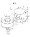
- FIG. 1A is a perspective view showing an example of the arrangement of each member of the powder coating apparatus 5 according to the first embodiment of the present invention.
- the powder coating apparatus 5 of the first embodiment can be provided with a rotary stage 3, a first booth 10, a second booth 20, a powder coating introduction nozzle 30, a plasma irradiation device 40 and a control device 50.
- the powder coating apparatus 5 coats the metal cylindrical body 1 installed at a position indicated by a two-dot chain line with a powder paint.
- the powder coating apparatus 5 of the present invention is used for coating the metal cylinder 1 indicated by a two-dot chain line, but the metal cylinder 1 does not require coating on the inner peripheral surface 2 thereof. Therefore, the inner peripheral surface 2 on which the metal cylinder 1 is not coated is held by the chuck member 4 provided on the rotary stage 3.
- the rotation stage 3 includes a rotation unit 3A to which the chuck member 4 is attached, and a drive unit 3B that rotates the rotation unit 3A.
- the rotating unit 3A can be rotated at 5 to 1000 rpm by the driving unit 3B. Further, the rotary stage 3 can be moved up and down in the direction indicated by the arrow U by a lifting device (not shown), and the cylindrical metal body 1 can be raised to the position of the opening 25 of the second booth 20.
- the chuck member 4 includes a plurality of rod portions 4B and an arm portion 4A provided at the tip of the rod portion 4B, and a base portion of the rod portion 4B is projected on the rotating portion 3A.
- the number of rod portions 4B is four, but the number of rod portions 4B is not limited to four, and the inner peripheral surface 2 of the metal cylindrical body 1 can be reliably held by the arm portions 4A. Any number is acceptable as long as it is the number.
- 4 A of arm parts are attached in the direction orthogonal to the rod part 4B, and the front end surface of 4 A of arm parts opposes the internal peripheral surface 2 of the metal cylindrical body 1.
- the arm portion 4A can expand and contract in the direction of the inner peripheral surface 2 of the metal cylindrical body 1 indicated by the arrow E, and holds or releases the inner peripheral surface 2 of the metal cylindrical body 1. be able to. Since a well-known thing can be used about the expansion-contraction mechanism of 4 A of arm parts, description is abbreviate
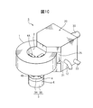
- FIG. 1B shows a state in which the inner peripheral surface 2 of the metal cylindrical body 1 is held by the chuck member 4 provided on the rotary stage 3.
- FIG. 1B shows only the metal cylinder 1, the rotary stage 3, the second booth 20, and the powder coating material introduction nozzle 30, and the other members are not shown.
- the first booth 10 is large enough to cover a part of the metal cylindrical body 1 held on the rotary stage 3, and the second booth 20 separates the first booth 10 across a predetermined internal space 21. It is a size that can be accommodated.
- the casing 14 on the side of the first booth 10 facing the metal cylinder 1 has an opening 15, and a part of the metal cylinder 1 is inserted into the opening 15.
- the housing 24 of the second booth 20 has an opening 25 at a position overlapping the opening 15 of the first booth 10, and a part of the metal cylinder 1 is inserted into the opening 25. Is done.
- the metal cylinder 1 can rotate while being inserted into the openings 15 and 25.
- the second booth 20 has a shape in which the width on the metal cylindrical body 1 side is narrowed, but the shape is not particularly limited.
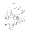
- FIG. 1C shows a state in which a part of the metal cylindrical body 1 held by the chuck member 4 of the rotary stage 3 is inserted into the opening 25.
- FIG. 1C shows only the metal cylindrical body 1, the rotary stage 3, the second booth 20, and the powder coating material introduction nozzle 30, and the other members are not shown.
- the powder coating introduction nozzle 30 includes one powder coating inlet 31 located outside the second booth 20.
- the powder coating material introduction nozzle 30 is branched into a plurality of branch pipes 33 inside the second booth 20, and the plurality of branch pipes 33 are inserted into the first booth 10.
- tip part of the some branch pipe 33 are mentioned later.
- the pulverized fuel injected from the powder coating inlet 31 of the powder coating introduction nozzle 30 can be injected using a coating gun described later.
- a blow device 13 including a pipe 12 that can inject an air flow into the booth is connected to a side surface of the housing 14.
- the second booth 20 is connected to a dust collector 23 having a hose 22 for sucking the powder paint remaining inside.
- the dust collector 23 can store the powder paint collected by suction.
- the blower 13 does not operate.
- the blow device 13 operates after finishing the painting, and the air sucked from the suction port 16 is injected into the first booth 10.
- the powder coating material staying in the first booth 10 is pushed out into the internal space 21 of the second booth 20 and sucked up by the dust collector 23. It is.
- the plasma irradiation device 40 is provided at a position where it does not interfere with the second booth 20 with respect to the metal cylinder 1 held on the rotary stage 3. Although the internal configuration of the plasma irradiation apparatus 40 will be described later, the plasma irradiation apparatus 40 is connected to a plasma gas supply source 42 through a pipe 43 and is connected to a plasma power supply 44 through a cord 45. The plasma irradiation device 40 irradiates plasma to the metal cylinder 1 to improve the adhesion of the powder coating material to the surface of the metal cylinder 1.
- the powder coating device 5 may or may not be provided with the plasma irradiation device 40.
- FIG. 1C shows a case where the plasma irradiation apparatus 40 is not provided in the powder coating apparatus 5, and FIG.
- FIG. 1D shows a case where the plasma irradiation apparatus 40 is provided in the powder coating apparatus 5.
- FIG. 1D shows only the metal cylinder 1 and the rotary stage 3, the second booth 20, the powder coating material introduction nozzle 30 and the plasma irradiation device 40, and other members are not shown.
- the blower 13, the dust collector 23, and the plasma power supply 44 are connected to a controller 50 that controls these operations.
- the control device 50 can also perform rotation control of the rotary stage 3, control of air injection into the first booth 10 by the blow device, and suction control of the dust collector 23. The control of the control device 50 will be described later.
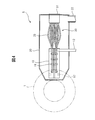
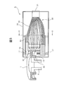
- FIG. 2 is a sectional view showing a first embodiment of the powder coating apparatus 5 of the present invention.
- the powder coating apparatus 5 of the first embodiment is not provided with a plasma irradiation apparatus.
- a metal cylindrical body 1 that is a material to be coated is installed on a rotary stage 3.
- the metal cylinder 1 is inserted into the first booth 10 with the rotary stage 3 lowered.
- the rotary stage 3 is raised and the chuck member 4 is inserted inside the inner peripheral surface 2 of the metal cylinder 1.
- the chuck member 4 is closed.
- the chuck member 4 When the chuck member 4 reaches a predetermined position inside the inner peripheral surface 2 of the metal cylindrical body 1, the chuck member 4 is opened and the inner peripheral surface 2 of the metal cylindrical body 1 is held by the chuck member 4.
- the chuck member 4 is made of a conductive metal and is grounded to the earth potential.
- the powder coating apparatus 5 shown in FIG. 1C corresponds to the state of the first embodiment.
- the branch pipe 33 of the powder coating material introduction nozzle 30 When the metal cylinder 1 is inserted into the first booth 10, the branch pipe 33 of the powder coating material introduction nozzle 30 is retracted so as not to interfere with the metal cylinder 1, and the metal cylinder 1 is rotated. 3 is held by the chuck member 4, the position of the nozzle 32 of the branch pipe 33 is directed to the coating position. For this reason, the branch pipe 33 of the powder coating material introduction nozzle 30 can be deformed, and can be made of a flexible material capable of freely changing the position of the nozzle 32 in the first booth 10 and maintaining the position. ing. In addition, since it is not necessary to change especially the part located in the 2nd booth 20 of the branch pipe 33, this part does not need to be formed with a flexible material.
- the first booth 10 and the second booth 20 can be opened and closed. Further, when the metal cylinder 1 is held by the chuck member 4, the first and second booths 10 and 20 are kept away from the metal cylinder 1, and when the metal cylinder 1 is held by the chuck member 4, It is also possible to move the second booth 10 and insert the metal cylinder 1 therein.
- the dust collector 23 starts operating by the control device 50 shown in FIG. 1A (not shown in FIG. 2). Then, the air inside the second booth 20 is sucked through the hose 22 as indicated by an arrow V. Next, the rotary stage 3 rotates, and the powder coating material is discharged from the coating gun 6 into the injection port 31.
- the powder paint passes through each branch pipe 33 and is ejected from each nozzle 32 toward the surface of the metal cylindrical body 1.
- the number of branch pipes 33 of the powder coating material introduction nozzle 30 increases, the paint distribution ratio to the application portion can be finely controlled. However, the positioning of the branch pipes 33 is dense, and the arrangement becomes difficult. For this reason, the number of branch pipes 33 is preferably between 10 and 30 in order to facilitate the arrangement of each nozzle 32 while ensuring supply distribution control.
- a predetermined amount of the powder paint ejected from each nozzle 32 of the powder paint introduction nozzle 30 toward the metal cylinder 1 is directly attached to the surface of the metal cylinder 1, and the powder paint not attached is the first.
- the first booth 10 is also referred to as a powder paint retention booth. Since the powder paint staying in the first booth 10 is charged, it is attracted by the adherend and electrostatic attraction during the stay and adheres to the surface of the metal cylinder 1. Accordingly, the adhesion rate of the powder coating material sprayed from each nozzle 32 of the powder coating material introduction nozzle 30 toward the metal cylinder 1 to the surface of the metal cylinder 1 is improved.
- the blowing device 13 is not operating, and air is not injected into the first booth 10 from the outside.
- the first booth 10 is provided inside the second booth 20 and the booth has a double structure, and the coating is performed while the powder paint is retained in the first booth 10, the booth has a single structure.
- the ratio of the powder coating material adhering to the surface of the metal cylindrical body 1 increases.
- the amount of powder paint that can be reused is reduced, the amount of powder paint that deteriorates is reduced, and the utilization rate of the powder paint is improved.
- the utilization factor of the powder coating was improved from 90% to 95%.
- the powder fuel that has not adhered to the surface of the metal cylinder 1 in the first booth 10 and stays in the first booth 10 and then overflows into the second booth 20 is collected. It is sucked by the dust device 23.
- the pulverized fuel can be collected in the dust collector 23 without scattering the powder paint outside the first and second booths 10 and 20.
- the volume of the second booth 20 can be reduced to about 1/00 as compared with a general powder coating booth, but the suction capacity and the processing capacity are the same as those of the conventional dust collectors. For this reason, the dust collector 23 of the present invention can be reduced in size to about 1/100 of conventional dust collectors without changing the suction capability and processing capability.
- the discharge of the powder paint from the coating gun 6 is stopped by the control device 50 shown in FIG. 1A.
- the first and second booths 10 and 20 are separated from the metal cylindrical body 1 by the control device 50 (this state corresponds to FIG. 1B).
- the metal cylinder 1 can be removed from the rotary stage 3. The removed metal cylinder 1 is conveyed to a heat treatment process for baking the coating film.
- the metal cylinder 1 After the metal cylinder 1 is taken out, air is sent to the first booth 10 by the control device 50 through the pipe 12 as indicated by the arrow A, and air blow of the first booth 10 is performed. By this air blow, the powder paint remaining in the first booth 10 is blown out to the second booth 20 side, and the powder paint in the first booth 10 is removed. At this time, the powder paint blown out from the first booth 10 by air blow is transferred to the second booth 20 and then collected by the dust collector 23 shown in FIG. 1A. For this reason, the second booth 20 is also called a dust collection booth.
- FIG. 3 is a sectional view showing a second embodiment of the powder coating apparatus 5 of the present invention.
- the powder coating apparatus 5 of the second embodiment is provided with a plasma irradiation apparatus 40. Since the operation of the portion other than the plasma irradiation apparatus 40 in the second embodiment is the same as that of the first embodiment, the same components as those in the first embodiment are denoted by the same reference numerals and description of the operation is omitted. To do.
- the powder coating apparatus 5 shown in FIG. 1D corresponds to the state of the second embodiment.
- the plasma irradiation apparatus 40 is provided at a position on the opposite side of the first and second booths 10 and 20 with the rotary stage 3 as the center.
- the plasma irradiation apparatus 40 is provided with a plurality of plasma irradiation nozzles 41 according to the shape of the metal cylindrical body 1.
- Each plasma irradiation nozzle 41 is supplied with AC power from a plasma power supply 44 and supplied with plasma gas from a plasma gas supply source 42 through a pipe 43.
- the plasma gas is a mixture of Ar, O 2 , H 2 , N 2 and air.
- the metal cylindrical body 1 is held on the rotary stage 3, and after the rotary stage 3 is rotated by the control device 50 (not shown in FIG. 3) shown in FIG. Operate.
- the plasma irradiation apparatus 40 plasma gas is supplied from the plasma gas supply source 42 through the pipe 43, and in this state, the plasma power supply 44 is turned on, and an atmospheric pressure plasma stream flows from the plasma irradiation nozzle 41 to the surface of the metal cylinder 1. Irradiated.
- the control device 50 turns off the plasma power supply 44, the supply of plasma gas from the plasma gas supply source 42 is stopped, and the plasma irradiation nozzle 41. The plasma irradiation from stops.
- the dust collector 23 starts to operate by the control device 50, and the air inside the second booth 20 is sucked through the hose 22 as indicated by the arrow V.
- the discharge of the powder coating from the coating gun 6 is started in a state where the rotation stage 3 is kept rotating, and thereafter the coating using the powder coating on the surface of the metal cylindrical body 1 is performed as in the first embodiment. Is started.
- plasma irradiation which is a pretreatment for coating, is performed on the metal cylinder 1.
- the powder coating apparatus of the present invention can improve the adhesion of the powder coating to the surface of the metal cylinder 1 by about 20% compared to the conventional powder coating apparatus in which the plasma irradiation apparatus is placed nearby. I understood.
- FIGS. 4 is a horizontal sectional view of the powder coating apparatus 5 of the present invention
- FIG. 5 is a vertical sectional view of the powder coating apparatus 5 shown in FIG. 4,
- FIG. It is sectional drawing in the XX line.
- the first booth 10 is fixed in the second booth 20 by four supports 17.
- a through-hole 18 through which the branch pipe 33 of the powder coating material introduction nozzle 30 passes is provided on the back surface of the casing 14 of the first booth 10. It passes through the through hole 18 and enters the first booth 10.
- two rows of thirteen through-holes 18 arranged in the vertical direction are provided, and the total number of through-holes 18 is 26.
- the height of the opening 25 opened in the casing 24 of the second booth 20 is larger than the height of the metal cylinder 1, and the metal cylinder 1 touches the casing 24 in the opening 25. It turns out that it can rotate without.
- the distance (clearance) between the metal cylinder 1 and the opening 25 in the height direction when a part of the metal cylinder 1 is inserted into the opening 25 opened in the housing 24 of the second booth 20 Between 2 mm and 20 mm. This is because when the distance between the metal cylinder 1 and the opening 25 in the height direction is smaller than 2 mm, the powder coating material adhering to the surface of the metal cylinder 1 in the first booth 10 is directed to the second booth 20 side. Because it will be sucked out. When the distance between the metal cylindrical body 1 and the opening 25 in the height direction is larger than 20 mm, the powder coating sprayed to the first booth 10 passes through the second booth 20 and the powder coating apparatus 5 This is because it scatters around.
- a stay 19 for fixing the branch pipes 33 of the plurality of synthetic resin powder coating introduction nozzles 30 is provided in the first booth 10.
- the branch pipe 33 can use the stay 19 to adjust the position of the nozzle hole 32 at the tip to the position where the surface of the metal cylindrical body 1 is desired to be painted as shown in FIG.
- a block having a hole can be used, and the branch pipe 33 can be inserted into the hole of the block and fixed.
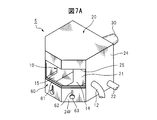
- FIG. 7A shows the configuration of the second booth 20 that includes the powder paint introduction nozzle 30 and incorporates the first booth 10 in the powder coating apparatus 5 according to the second embodiment of the present invention.
- the second booth 20 there are the same rotary stage 3, blower 13, dust collector 23, plasma irradiation device 40, plasma gas supply source 42 as the powder coating device 5 of the first embodiment shown in FIG. 1A.
- the plasma power supply 44 and the control device 50 can be arranged.
- the powder coating apparatus 5 according to the second embodiment of the present invention can prevent the powder paint from being scattered outside the second booth 20 even when the height of the metal cylinder 1 changes. Is different from the powder coating apparatus 5 of the first embodiment.
- the opening part height adjustment mechanism 60 which can change the height of the opening part 25 inside the opening part 25 of the 2nd booth 20 is demonstrated.
- the opening height adjusting mechanism 60 includes a slide plate 61, a guide groove 62, and an operation knob 63.
- the slide plate 61 moves up and down along the inner method of the housing front part 24F located below the opening 25 of the second booth 20 to change the height of the opening 25. It is hidden behind the part 24F.
- the guide groove 62 determines the moving distance of the slide plate 25 in the vertical direction, and is provided in all of the three housing front portions 24F.
- the shaft of the operation knob 63 is attached to the slide plate 61 through the guide groove 62, and the slide plate 61 moves in the vertical direction by moving the shaft up and down from the outside.
- FIG. 7B shows a state where the slide plate 61 shown in FIG. 7A is moved upward by the operation of the operation knob 63 and the distance in the height direction of the opening 25 is narrowed.
- the shaft of the operation knob 63 is a screw, and the operation knob 63 is fixed to the housing front surface portion 24F when rotated in the right direction. Therefore, in order to change from the state shown in FIG. 7A to the state shown in FIG. 7B, the operation knob 63 shown in FIG. 7A is rotated to the left so that the slide plate 61 can move with respect to the housing front portion 24F. The slide plate 61 is moved upward by the knob 63.
- the operation knob 63 is rotated to the right at that position to slide the slide plate 61. 61 is fixed in that position.
- the structure of the opening height adjusting mechanism 60 is not limited to the structure of this embodiment.
- FIG. 7C shows a state in which a part of the metal cylinder 1 in which the inner peripheral surface 2 is held by the arm portion 4A of the chuck member 4 of the rotary stage 3 is inserted into the opening 25 in the second booth 20. Is shown.
- the metal cylinder 1 has a small axial height, and when the metal cylinder 1 is inserted into the opening 25 of the second booth 20 in the first form, the metal cylinder 1 is large between the opening 25 and the metal cylinder 1. A gap is formed, and the powder coating material scatters from the gap to the outside of the second booth 20 during powder coating.
- the distance in the height direction between the metal cylinder 1 and the opening 25 is reduced by pulling up the slide plate 61 of the opening height adjusting mechanism 60. It can be adjusted between 2 mm and 20 mm on the upper side and the lower side of the cylindrical body 1, respectively.
- the powder coating apparatus 5 according to the second embodiment is in a state in which the powder paint is prevented from being scattered to the surroundings at the time of powder coating with respect to various types of metal cylinders 1 having different axial heights. Can be used for powder coating.
- the metal cylinder 1 is exemplified as the member to be coated, and the powder coating apparatus that performs powder coating on the metal cylinder 1 has been described.
- the member to be coated is not limited to a metal cylindrical body, and any member may be used as long as it is a cylindrical member that does not require coating on the inner peripheral surface held by the chuck member.
- the shape of the cylinder is not a cylinder, but may be a rectangular cylinder or a polygonal cylinder.
Landscapes
- Electrostatic Spraying Apparatus (AREA)
- Application Of Or Painting With Fluid Materials (AREA)
- Coating Apparatus (AREA)
- Details Or Accessories Of Spraying Plant Or Apparatus (AREA)
Abstract
Priority Applications (3)
| Application Number | Priority Date | Filing Date | Title |
|---|---|---|---|
| US14/384,459 US9216433B2 (en) | 2012-03-21 | 2012-10-09 | Powder coating system |
| DE201211006121 DE112012006121T5 (de) | 2012-03-21 | 2012-10-09 | Pulverbeschichtungssystem |
| CN201280071620.3A CN104203424B (zh) | 2012-03-21 | 2012-10-09 | 粉体涂装装置 |
Applications Claiming Priority (2)
| Application Number | Priority Date | Filing Date | Title |
|---|---|---|---|
| JP2012-063563 | 2012-03-21 | ||
| JP2012063563A JP5712955B2 (ja) | 2012-03-21 | 2012-03-21 | 粉体塗装装置 |
Publications (1)
| Publication Number | Publication Date |
|---|---|
| WO2013140647A1 true WO2013140647A1 (fr) | 2013-09-26 |
Family
ID=49222136
Family Applications (1)
| Application Number | Title | Priority Date | Filing Date |
|---|---|---|---|
| PCT/JP2012/076132 Ceased WO2013140647A1 (fr) | 2012-03-21 | 2012-10-09 | Dispositif d'application d'une poudre en revêtement |
Country Status (5)
| Country | Link |
|---|---|
| US (1) | US9216433B2 (fr) |
| JP (1) | JP5712955B2 (fr) |
| CN (1) | CN104203424B (fr) |
| DE (1) | DE112012006121T5 (fr) |
| WO (1) | WO2013140647A1 (fr) |
Cited By (1)
| Publication number | Priority date | Publication date | Assignee | Title |
|---|---|---|---|---|
| JP2015536231A (ja) * | 2012-10-10 | 2015-12-21 | ユーロサイダー エス.エイ.エス. ディ ミッリ オッタヴィオ アンド シー. | 静電塗装のための方法および装置 |
Families Citing this family (11)
| Publication number | Priority date | Publication date | Assignee | Title |
|---|---|---|---|---|
| ITMO20100263A1 (it) * | 2010-09-21 | 2012-03-22 | Vincenzo Rina | Apparecchiatura per la verniciatura di scafi di imbarcazioni navali o simili |
| KR101509864B1 (ko) * | 2012-11-07 | 2015-04-06 | (주)엘지하우시스 | 비산 파우더 크리닝 장치 |
| JP2015100761A (ja) * | 2013-11-26 | 2015-06-04 | 曙ブレーキ工業株式会社 | 支持具、粉体塗布システム、粉体塗布方法、及びキャリパ |
| JP6432236B2 (ja) * | 2014-09-17 | 2018-12-05 | 富士ゼロックス株式会社 | 粉体塗装装置、及び粉体塗装方法 |
| CN106076759A (zh) * | 2016-07-25 | 2016-11-09 | 铜陵海源超微粉体有限公司 | 粉体涂装装置 |
| CN111151406B (zh) * | 2020-01-06 | 2021-06-01 | 青岛博展智能科技有限公司 | 一种用于静电喷涂的喷涂室 |
| CN114308435B (zh) * | 2022-03-08 | 2022-05-27 | 季华实验室 | 喷涂送粉装置 |
| CN115318530B (zh) * | 2022-10-18 | 2023-04-11 | 南通康普来精密工业有限公司 | 一种汽车配件加工喷涂设备 |
| CN119082654A (zh) * | 2024-08-30 | 2024-12-06 | 新昌县新鑫滤器有限公司 | 一种化纤机械配件生产热喷涂设备 |
| CN120885362B (zh) * | 2025-10-09 | 2025-11-28 | 苏州荣文库柏照明系统股份有限公司 | 一种用于粉末喷涂生产工艺的智能悬挂输送系统 |
| CN121607275B (zh) * | 2026-02-03 | 2026-03-27 | 上海联合滚动轴承有限公司 | 地铁轴承表面喷涂防锈设备 |
Citations (6)
| Publication number | Priority date | Publication date | Assignee | Title |
|---|---|---|---|---|
| US3731340A (en) * | 1971-08-09 | 1973-05-08 | H Pitre | Motor vehicle brake drum cleaning apparatus |
| JPS5965757U (ja) * | 1982-10-20 | 1984-05-02 | ナショナル住宅産業株式会社 | スプレ−ガン |
| JPH07155652A (ja) * | 1993-12-07 | 1995-06-20 | Chichibu Onoda Cement Corp | 静電粉体塗装方法及びその装置 |
| JPH0910638A (ja) * | 1995-07-03 | 1997-01-14 | Unix:Kk | 自動塗装装置 |
| JP2001276688A (ja) * | 2000-03-31 | 2001-10-09 | Kurimoto Ltd | 管外面塗装装置 |
| JP2005013931A (ja) * | 2003-06-27 | 2005-01-20 | Nisca Corp | 粉体塗装装置 |
Family Cites Families (17)
| Publication number | Priority date | Publication date | Assignee | Title |
|---|---|---|---|---|
| US1368338A (en) * | 1916-12-18 | 1921-02-15 | Wire Wheel Corp | Painting-booth |
| US2781279A (en) * | 1951-11-26 | 1957-02-12 | Ransburg Electro Coating Corp | Method and apparatus for spray coating of articles |
| US3913523A (en) * | 1972-08-07 | 1975-10-21 | Ransburg Electro Coating Corp | Powder coating apparatus |
| US4244318A (en) * | 1979-12-31 | 1981-01-13 | Sperry Corporation | Thin particulate film spin coater |
| US4386578A (en) * | 1981-05-26 | 1983-06-07 | The Boeing Company | High velocity metallic mass increment vacuum deposit gun |
| US4567818A (en) * | 1983-04-20 | 1986-02-04 | Protectaire Systems Co. | Circular spray booth |
| US4787330A (en) * | 1987-12-22 | 1988-11-29 | Bolf Carl R | Self-cleaning powder coating booth |
| US5079043A (en) * | 1990-12-03 | 1992-01-07 | The Perkin-Elmer Corporation | Method for spraying a coating on a disk |
| US5288324A (en) * | 1992-12-18 | 1994-02-22 | Shaneyfelt Jack L | Multi-color powder coat paint recovery apparatus |
| SG74728A1 (en) * | 1998-06-02 | 2000-08-22 | Kuroda Precision Ind Ltd | Method for electrostatic coating a metallic cylindrical body |
| US20040200418A1 (en) * | 2003-01-03 | 2004-10-14 | Klaus Hartig | Plasma spray systems and methods of uniformly coating rotary cylindrical targets |
| US7968353B2 (en) * | 2008-04-15 | 2011-06-28 | Global Solar Energy, Inc. | Apparatus and methods for manufacturing thin-film solar cells |
| DE102009060649A1 (de) * | 2009-12-22 | 2011-06-30 | EISENMANN Anlagenbau GmbH & Co. KG, 71032 | Anlage zur Oberflächenbehandlung von Gegenständen |
| CN102371217B (zh) * | 2011-10-30 | 2016-05-04 | 瑞阳汽车零部件(仙桃)有限公司 | 封闭式漆粉循环利用喷漆系统 |
| US20150017897A1 (en) * | 2013-07-10 | 2015-01-15 | Thomas Wiliams | System and Method for Maintaining Airflow within an Inflatable Booth |
| US9958168B2 (en) * | 2014-01-28 | 2018-05-01 | Illinois Tool Works Inc. | Cooking exhaust hood ventilation system and related methods |
| DE102016120446B4 (de) | 2016-10-26 | 2023-03-30 | Andreas Von Keitz | Kupplungsvorrichtung zur Kopplung von Leitungen für den Außenbereich |
-
2012
- 2012-03-21 JP JP2012063563A patent/JP5712955B2/ja not_active Expired - Fee Related
- 2012-10-09 WO PCT/JP2012/076132 patent/WO2013140647A1/fr not_active Ceased
- 2012-10-09 CN CN201280071620.3A patent/CN104203424B/zh not_active Expired - Fee Related
- 2012-10-09 US US14/384,459 patent/US9216433B2/en not_active Expired - Fee Related
- 2012-10-09 DE DE201211006121 patent/DE112012006121T5/de not_active Withdrawn
Patent Citations (6)
| Publication number | Priority date | Publication date | Assignee | Title |
|---|---|---|---|---|
| US3731340A (en) * | 1971-08-09 | 1973-05-08 | H Pitre | Motor vehicle brake drum cleaning apparatus |
| JPS5965757U (ja) * | 1982-10-20 | 1984-05-02 | ナショナル住宅産業株式会社 | スプレ−ガン |
| JPH07155652A (ja) * | 1993-12-07 | 1995-06-20 | Chichibu Onoda Cement Corp | 静電粉体塗装方法及びその装置 |
| JPH0910638A (ja) * | 1995-07-03 | 1997-01-14 | Unix:Kk | 自動塗装装置 |
| JP2001276688A (ja) * | 2000-03-31 | 2001-10-09 | Kurimoto Ltd | 管外面塗装装置 |
| JP2005013931A (ja) * | 2003-06-27 | 2005-01-20 | Nisca Corp | 粉体塗装装置 |
Cited By (1)
| Publication number | Priority date | Publication date | Assignee | Title |
|---|---|---|---|---|
| JP2015536231A (ja) * | 2012-10-10 | 2015-12-21 | ユーロサイダー エス.エイ.エス. ディ ミッリ オッタヴィオ アンド シー. | 静電塗装のための方法および装置 |
Also Published As
| Publication number | Publication date |
|---|---|
| US20150101531A1 (en) | 2015-04-16 |
| US9216433B2 (en) | 2015-12-22 |
| CN104203424B (zh) | 2017-03-01 |
| DE112012006121T5 (de) | 2014-12-24 |
| CN104203424A (zh) | 2014-12-10 |
| JP5712955B2 (ja) | 2015-05-07 |
| JP2013193038A (ja) | 2013-09-30 |
Similar Documents
| Publication | Publication Date | Title |
|---|---|---|
| WO2013140647A1 (fr) | Dispositif d'application d'une poudre en revêtement | |
| CN104271254B (zh) | 用于喷涂设备的干冰清洁装置及方法 | |
| CN105562383A (zh) | 用于涂覆系统的一个或多个部件的清洁方法和清洁装置 | |
| CN108525889B (zh) | 一种喷涂机器人及其喷涂方法 | |
| KR20160124451A (ko) | 자동 도장장치 | |
| CN112007775A (zh) | 一种喷涂范围可调式建筑装修装饰用喷涂机 | |
| JP7229708B2 (ja) | 塗装装置 | |
| JPH11501579A (ja) | 回転静電気散布装置および方法 | |
| CN115335156A (zh) | 用于汽车轮辋的涂覆柜 | |
| US20110250364A1 (en) | Powder coating apparatus and powder coating method | |
| US6827780B2 (en) | Method and apparatus for powder coating hollow objects | |
| JP2021058838A (ja) | 塗装ブースおよび塗装方法 | |
| US9138765B2 (en) | Coating device for workpieces and method for operating the coating device | |
| JP2013071049A (ja) | 塗装装置及びそれを用いた塗装方法 | |
| JP6156062B2 (ja) | 粉体塗装装置および粉体塗装方法 | |
| CN101151102A (zh) | 成膜装置 | |
| JP2008279340A (ja) | 摩擦帯電式静電塗装装置 | |
| CN104981296A (zh) | 用于鞣制皮革的外部处理的系统和方法 | |
| US9399232B2 (en) | Electrostatic spray tool system | |
| JP2002177826A (ja) | 静電粉体塗装装置 | |
| JP2011240315A (ja) | 塗装用ノズル、及び塗装用ノズルを用いた塗装装置 | |
| US9221066B2 (en) | Multi-head electrostatic painting apparatus | |
| JP2007260579A (ja) | 塗装装置 | |
| JP2004089948A (ja) | 粉体塗装ブース | |
| JPH02152568A (ja) | 回転霧化式塗装装置 |
Legal Events
| Date | Code | Title | Description |
|---|---|---|---|
| 121 | Ep: the epo has been informed by wipo that ep was designated in this application |
Ref document number: 12871807 Country of ref document: EP Kind code of ref document: A1 |
|
| WWE | Wipo information: entry into national phase |
Ref document number: 14384459 Country of ref document: US |
|
| WWE | Wipo information: entry into national phase |
Ref document number: 112012006121 Country of ref document: DE Ref document number: 1120120061217 Country of ref document: DE |
|
| 122 | Ep: pct application non-entry in european phase |
Ref document number: 12871807 Country of ref document: EP Kind code of ref document: A1 |