WO2013140899A1 - Dispositif de purification par stérilisation - Google Patents
Dispositif de purification par stérilisation Download PDFInfo
- Publication number
- WO2013140899A1 WO2013140899A1 PCT/JP2013/053368 JP2013053368W WO2013140899A1 WO 2013140899 A1 WO2013140899 A1 WO 2013140899A1 JP 2013053368 W JP2013053368 W JP 2013053368W WO 2013140899 A1 WO2013140899 A1 WO 2013140899A1
- Authority
- WO
- WIPO (PCT)
- Prior art keywords
- sterilization
- container
- lid
- water
- sterilization chamber
- Prior art date
- Legal status (The legal status is an assumption and is not a legal conclusion. Google has not performed a legal analysis and makes no representation as to the accuracy of the status listed.)
- Ceased
Links
Images





Classifications
-
- C—CHEMISTRY; METALLURGY
- C02—TREATMENT OF WATER, WASTE WATER, SEWAGE, OR SLUDGE
- C02F—TREATMENT OF WATER, WASTE WATER, SEWAGE, OR SLUDGE
- C02F1/00—Treatment of water, waste water, or sewage
- C02F1/30—Treatment of water, waste water, or sewage by irradiation
- C02F1/32—Treatment of water, waste water, or sewage by irradiation with ultraviolet light
- C02F1/325—Irradiation devices or lamp constructions
-
- C—CHEMISTRY; METALLURGY
- C02—TREATMENT OF WATER, WASTE WATER, SEWAGE, OR SLUDGE
- C02F—TREATMENT OF WATER, WASTE WATER, SEWAGE, OR SLUDGE
- C02F2201/00—Apparatus for treatment of water, waste water or sewage
- C02F2201/002—Construction details of the apparatus
- C02F2201/004—Seals, connections
-
- C—CHEMISTRY; METALLURGY
- C02—TREATMENT OF WATER, WASTE WATER, SEWAGE, OR SLUDGE
- C02F—TREATMENT OF WATER, WASTE WATER, SEWAGE, OR SLUDGE
- C02F2201/00—Apparatus for treatment of water, waste water or sewage
- C02F2201/32—Details relating to UV-irradiation devices
- C02F2201/322—Lamp arrangement
- C02F2201/3223—Single elongated lamp located on the central axis of a turbular reactor
-
- C—CHEMISTRY; METALLURGY
- C02—TREATMENT OF WATER, WASTE WATER, SEWAGE, OR SLUDGE
- C02F—TREATMENT OF WATER, WASTE WATER, SEWAGE, OR SLUDGE
- C02F2201/00—Apparatus for treatment of water, waste water or sewage
- C02F2201/32—Details relating to UV-irradiation devices
- C02F2201/322—Lamp arrangement
- C02F2201/3228—Units having reflectors, e.g. coatings, baffles, plates, mirrors
-
- C—CHEMISTRY; METALLURGY
- C02—TREATMENT OF WATER, WASTE WATER, SEWAGE, OR SLUDGE
- C02F—TREATMENT OF WATER, WASTE WATER, SEWAGE, OR SLUDGE
- C02F2303/00—Specific treatment goals
- C02F2303/04—Disinfection
-
- C—CHEMISTRY; METALLURGY
- C02—TREATMENT OF WATER, WASTE WATER, SEWAGE, OR SLUDGE
- C02F—TREATMENT OF WATER, WASTE WATER, SEWAGE, OR SLUDGE
- C02F2307/00—Location of water treatment or water treatment device
- C02F2307/12—Location of water treatment or water treatment device as part of household appliances such as dishwashers, laundry washing machines or vacuum cleaners
-
- D—TEXTILES; PAPER
- D06—TREATMENT OF TEXTILES OR THE LIKE; LAUNDERING; FLEXIBLE MATERIALS NOT OTHERWISE PROVIDED FOR
- D06F—LAUNDERING, DRYING, IRONING, PRESSING OR FOLDING TEXTILE ARTICLES
- D06F39/00—Details of washing machines not specific to a single type of machines covered by groups D06F9/00 - D06F27/00
- D06F39/08—Liquid supply or discharge arrangements
- D06F39/088—Liquid supply arrangements
Definitions
- This embodiment relates to a sterilization purification apparatus.
- washing machines are equipped with a sterilization and purification device.
- This sterilization purification device sterilizes bath water. Bath water is sterilized and used as water for washing clothes or water for rinsing clothes.
- the conventional sterilization and purification device sterilizes water collected outside, for example, bath water with ozone or metal ions.
- bath water is sterilized with ozone
- a gas harmful to the human body may leak out from the sterilization and purification device.
- the metal ions may adhere to the clothes and discolor the clothes.
- the sterilization purification apparatus of the present embodiment includes a sterilization container, a first lid, a second lid, an inlet, an outlet, a protective tube, an ultraviolet projector, a first reflecting surface, and a second reflecting surface. And comprising.
- the sterilization container has a cylindrical shape having a first end and a second end, and an inner peripheral surface is covered with a reflective layer capable of reflecting ultraviolet rays.
- the first lid is fitted to the sterilization container at the first end.
- the second lid is fitted to the sterilization container at the second end.
- the inlet is provided in the sterilization container and supplies water to a sterilization chamber formed inside the sterilization container.
- the outlet is provided in a sterilization container and discharges water from the sterilization chamber.
- the protective tube is housed inside the sterilization chamber and can transmit ultraviolet rays.
- the ultraviolet projector is housed inside the protective tube.
- the first reflecting surface is provided on the first lid and is located inside the sterilization chamber and reflects ultraviolet rays.
- the second reflecting surface is provided on the second lid and is located inside the sterilization chamber and reflects ultraviolet rays.
- the sterilization and purification apparatus of the present embodiment may further include a partition member.
- This partition member has a protective tube and partitions the inside of the sterilization container into an inlet-side sterilization chamber and an outlet-side sterilization chamber along the axial direction of the sterilization container.
- the inlet may be configured to supply water into the inlet-side sterilization chamber.
- the partition member may be configured to have a water passage port for supplying water from the inside of the entrance side sterilization chamber to the inside of the exit side sterilization chamber.
- the outlet may be configured to discharge water from the inside of the outlet side sterilization chamber.
- FIG. 1 The figure which shows the internal structure of the washing machine which concerns on 1st Embodiment.
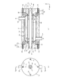
- A is a cross-sectional view of the sterilization and purification device along line Xa-Xa in (b), (b) is an end view of the sterilization and purification device viewed in the direction of arrow Xb in (a)
- A) is a cross-sectional view of the left lid taken along line Xa-Xa in (b)
- (b) is an end view of the left lid as viewed in the direction of arrow Xb in (a)
- (c) is in (a) End view of the left lid viewed in the direction of arrow Xc
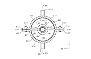
- Sectional view of the sterilization and purification device along line X6-X6 in FIG. (A) is a side view of the protective container as viewed in the direction of arrow Xd in (b)
- (b) is a plan view of the protective container as viewed in the direction of arrow Xe in (a)
- (c) is in
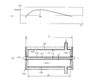
- (b) is a figure for demonstrating distance "r".
- the outer box 1 of the washing machine is installed on the floor surface.
- a water tank 2 is housed inside the outer box 1.
- the water tank 2 receives tap water or bath water and has a vertically long cylindrical shape having a bottom plate.
- a washing motor 3 is fixed to the bottom plate of the water tank 2 so as to be located outside the water tank 2.
- the washing motor 3 has a rotating shaft 4 that is oriented in the vertical direction.
- the rotating shaft 4 of the washing motor 3 is inserted into the water tank 2.
- the washing motor 3 has a clutch mechanism. The mechanical state of the clutch mechanism is switched between the washing mode and the dewatering mode.
- a washing tub 5 and a pulsator 6 are connected to the rotating shaft 4 of the washing motor 3.
- the washing tub 5 has a vertically long cylindrical shape having a bottom plate and is stored in the water tub 2.
- the washing tub 5 has a plurality of through holes. Tap water or bath water inside the water tub 2 can flow between the inside of the water tub 2 and the inside of the washing tub 5 through a plurality of through holes. Clothes are put into the washing tub 5.
- the pulsator 6 is stored at the bottom inside the washing tub 5.
- the pulsator 6 agitates water (tap water or bath water) and clothes inside the washing tub 5.
- the washing motor 3 is driven in a state where the clutch mechanism is in the washing mode, thereby rotating the pulsator 6 while the washing tub 5 is stationary. Moreover, the washing motor 3 rotates the washing tub 5 and the pulsator 6 by being driven in a state where the clutch mechanism is in the dewatering mode.
- a water supply valve 7 is fixed inside the outer box 1.
- the water supply valve 7 has an inlet 8.
- the inlet 8 of the water supply valve 7 is connected to a water tap through a hose.
- the water supply valve 7 has a water injection port 9 and a priming water port 10 and is switched to a closed state, a water injection state, and a priming state.
- the closed state is a state in which the water filling port 9 and the priming port 10 are closed.
- the water injection state is a state where the priming port 10 is closed and the water injection port 9 is opened.
- the priming state is a state in which the priming port 9 is closed and the priming port 10 is opened.
- a water injection case 11 is fixed inside the outer box 1.
- the water injection case 11 is connected to the water injection port 9 of the water supply valve 7 through a hose 12.
- tap water is injected into the water tank 2 through the water faucet 9, the hose 12, and the water pouring case 11 in this order.
- a water supply pump 13 is fixed inside the outer box 1.
- the feed water pump 13 is driven by a pump motor, and has an inlet 14, an outlet 15, and a priming port 16.
- a water supply port 18 is connected to the inlet 14 of the water supply pump 13 via a hose 17.
- the water supply port 18 is submerged in the bath water inside the bathtub 19.
- the priming port 16 of the water supply pump 13 is connected to the priming port 10 of the water supply valve 7 through a hose 20.
- tap water is supplied as priming water from the faucet through the priming port 10, the hose 20, and the priming port 16 to the water supply pump 13.
- a check valve 21 is interposed in the hose 20.
- the check valve 21 allows tap water to be supplied from the priming port 10 of the water supply valve 7 through the hose 20 to the priming port 16 of the water supply pump 13. Further, the check valve 21 prohibits bath water from being supplied from the priming port 16 of the water supply pump 13 through the hose 20 to the priming port 10 of the water supply valve 7.
- a sterilization and purification device 22 is fixed inside the outer box 1.
- the sterilization and purification device 22 has an inlet 23 and an outlet 24.
- the inlet 23 of the sterilization and purification device 22 is connected to the outlet 15 of the water supply pump 13 via a hose 25.
- the outlet 24 of the sterilization and purification device 22 is connected to the water injection case 11 via a hose 26.
- bath water is injected into the sterilizing and purifying device 22 from the outlet 15 of the feed water pump 13 through the hose 25 and the inlet 23 in order.
- the bath water injected into the sterilizing and purifying device 22 passes through the hose 26 and the water injection case 11 in order from the outlet 24 of the sterilizing and purifying device 22 and is injected into the water tank 2.
- a drain pipe 27 is connected to the water tank 2.
- a drain valve 28 is interposed in the drain pipe 27.
- the drain valve 28 is switched between a closed state and an open state.
- tap water or bath water injected from the inside of the water injection case 11 into the water tank 2 is stored in the water tank 2.
- tap water or bath water inside the water tank 2 is discharged to the outside through the drain pipe 27.
- the sterilization and purification device 22 purifies the sterilized bath water by sterilization.
- the bath water sterilized by the sterilization purification device 22 is injected into the water tank 2 through the water injection case 11.
- the bath water injected into the water tank 2 is used as water for washing clothes or as water for rinsing clothes.
- the detailed configuration of the sterilization and purification device 22 is as follows.
- a sterilization container 31 oriented in the left-right direction is fixed inside the outer box 1.
- the sterilization container 31 is formed by injection molding of a synthetic resin, and has a horizontal cylindrical shape with an open left end surface and right end surface.
- a cylindrical reflector 32 is fixed to the inner peripheral surface of the sterilization container 31.
- the reflecting plate 32 is a rolled stainless steel plate that can reflect ultraviolet rays, and covers the inner peripheral surface of the sterilization container 31. This reflection plate 32 corresponds to the reflection layer of the sterilization container.
- the reflectance of ultraviolet rays on the inner peripheral surface of the reflecting plate 32 is set higher than the reflectance of ultraviolet rays on the inner peripheral surface of the sterilization container 31.
- the reflectance is a numerical value representing the ratio between the energy of the reflected light and the energy of the incident light as a percentage when the ultraviolet rays are vertically incident.
- a left lid 33 and a right lid 34 are fixed to the sterilization container 31.
- the left lid 33 and the right lid 34 are formed by injection molding synthetic resin, and have a cylindrical plug 35 and a disc-shaped end plate 36.
- the plug 35 of the left lid 33 is fitted to the inner peripheral surface of the reflector 32 from the left side.
- the plug 35 of the right lid 34 is fitted to the inner peripheral surface of the reflector 32 from the right side.
- a spatial sterilization chamber 37 is formed between the plug 35 of the left lid 33, the plug 35 of the right lid 34, and the reflector 32.
- the left lid 33 corresponds to a first lid.
- the right lid 34 corresponds to a second lid.
- the end plate 36 of the left lid 33 and the end plate 36 of the right lid 34 have a plurality of through holes 38 as representatively shown in the left lid 33 in FIG.
- screws 39 are inserted into the plurality of through holes 38 of the left lid 33 from the left side.
- a screw 39 is inserted into the plurality of through holes 38 of the right lid 34 from the right side.
- a plurality of screws 39 of the left lid 33 are screwed into the left end surface of the sterilization container 31.
- the left lid 33 is fixed to the left end surface of the sterilization container 31 by fastening forces of a plurality of screws 39.
- a plurality of screws 39 of the right lid 34 are screwed into the right end surface of the sterilization container 31.
- the right lid 34 is fixed to the right end surface of the sterilization container 31 by fastening force by a plurality of screws 39.
- a rubber left packing 40 is inserted into the outer peripheral surface of the plug 35 of the left lid 33.
- the left packing 40 has an annular shape.
- a plurality of screws 39 of the left lid 33 are screwed into the left end surface of the sterilization container 31 through the left packing 40.
- the left packing 40 is elastically crushed by the fastening force of the plurality of screws 39 of the left lid 33.
- the left packing 40 is elastically restored and closely attached to the left end surface of the sterilization container 31, the left end surface of the reflection plate 32, and the end plate 36 of the left lid 33, so that the left end surface of the sterilization container 31 and the left lid
- the space between the 33 end plates 36 is sealed in a watertight state.
- the left packing 40 seals between the left end surface of the reflecting plate 32 and the end plate 36 of the left lid 33 in a watertight state.
- a rubber right packing 41 is inserted into the outer peripheral surface of the plug 35 of the right lid 34.
- the right packing 41 has an annular shape.
- a plurality of screws 39 of the right lid 34 are screwed into the right end surface of the sterilization container 31 through the right packing 41.
- the right packing 41 is elastically crushed by the fastening force of the plurality of screws 39 of the right lid 34.
- the right packing 41 is elastically restored and closely attached to the right end surface of the sterilization container 31, the right end surface of the reflection plate 32, and the end plate 36 of the right lid 34, so The space between the end plates 36 of 34 is sealed in a watertight state. Further, the right packing 41 seals between the right end surface of the reflecting plate 32 and the end plate 36 of the right lid 34 in a watertight state.
- a vertical cylindrical inlet 23 oriented in the vertical direction is fixed.
- the inlet 23 is formed by injection molding of a synthetic resin, and is arranged on a vertical straight line L passing through the axial line CL of the sterilization container 31 when viewed from the left-right direction.
- the upper end portion of the inlet 23 passes through the reflection plate 32 and is connected to the left end portion inside the sterilization chamber 37.
- the lower end portion of the inlet 23 is connected to the outlet 15 of the water supply pump 13 via the hose 25.
- a vertical cylindrical outlet 24 oriented in the vertical direction is fixed to the sterilization container 31.
- the outlet 24 is formed by injection-molding synthetic resin, and is disposed on a straight line L common to the inlet 23 when viewed from the left-right direction.
- a lower end portion of the outlet 24 passes through the reflection plate 32 and is connected to a right end portion inside the sterilization chamber 37.
- the upper end portion of the outlet 24 is connected to the inside of the water tank 2 through the hose 26 and the water injection case 11.
- the left lid 33 has a left lamp insertion hole 42 formed therein.
- the left lamp insertion hole 42 is a through hole oriented in the left-right direction, and is set in a circular shape concentric with the plug 35 and the end plate 36 of the left lid 33 when viewed from the left-right direction.
- a left lamp fixing rubber 43 is inserted into the left lamp insertion hole 42.
- the left lamp fixing rubber 43 has a cylindrical shape oriented in the left-right direction, and the outer diameter in the natural state is set larger than the inner diameter of the left lamp insertion hole 42.
- the left lamp fixing rubber 43 is elastically deformed by being pushed by the wall surface of the left lamp insertion hole 42.
- the left lamp fixing rubber 43 is fixed to the left lid 33 in a state in which the left lamp fixing rubber 43 is elastically restored to the wall surface of the left lamp insertion hole 42.
- the left lamp fixing rubber 43 corresponds to a first fixing member.
- the left lamp insertion hole 42 corresponds to a first through hole.
- the right lid 34 has a right lamp insertion hole 44 formed therein.
- the right lamp insertion hole 44 is a through-hole oriented in the left-right direction, and is set in a circular shape concentric with the plug 35 and the end plate 36 of the right lid 34 when viewed from the left-right direction.
- a right lamp fixing rubber 45 is inserted into the right lamp insertion hole 44.
- the right lamp fixing rubber 45 has a cylindrical shape that is oriented in the left-right direction, and the outer diameter in the natural state is set larger than the inner diameter of the right lamp insertion hole 44.
- the right lamp fixing rubber 45 is elastically deformed by being pushed by the wall surface of the right lamp insertion hole 44.
- the right lamp fixing rubber 45 is fixed to the right lid 34 in a state of being elastically restored to the wall surface of the right lamp insertion hole 44.
- the right lamp fixing rubber 45 corresponds to a second fixing member.
- the right lamp insertion hole 44 corresponds to a second through hole.
- a UV lamp 46 is housed inside the sterilization container 31.
- the UV lamp 46 is a cold cathode lamp that does not require external heating energy to emit electrons from the cathode, and has no filament.
- the UV lamp 46 has a horizontal cylindrical glass tube directed in the left-right direction, and projects ultraviolet rays for sterilization having a wavelength of, for example, 254 nm.
- This glass tube is formed of quartz glass that can transmit ultraviolet rays.
- An inert gas such as argon and mercury are sealed inside the glass tube.
- the left end portion of the glass tube is inserted into the inner peripheral surface of the left lamp fixing rubber 43.
- the right end of the glass tube is inserted into the inner peripheral surface of the right lamp fixing rubber 45.
- the UV lamp 46 corresponds to an ultraviolet lamp that is an ultraviolet projector.
- the outer diameter of the glass tube of the UV lamp 46 is set larger than the inner diameter of the left lamp fixing rubber 43 in the natural state and the inner diameter of the right lamp fixing rubber 45 in the natural state.
- the left lamp fixing rubber 43 and the right lamp fixing rubber 45 are elastically deformed when pressed against the outer peripheral surface of the glass tube.
- the left end of the glass tube is fixed to the left lid 33 via the left lamp fixing rubber 43 by the left lamp fixing rubber 43 being elastically restored and closely contacting the outer peripheral surface of the glass tube.
- the right end of the glass tube is fixed to the right lid 34 via the right lamp fixing rubber 45 by the right lamp fixing rubber 45 being elastically restored and closely contacting the outer peripheral surface of the glass tube.
- the glass tube of the UV lamp 46 is housed inside the sterilization chamber 37 except for the left end and the right end.
- the axial center line of the glass tube is overlapped with the axial center line CL of the sterilization container 31.
- An electrode 47 is fitted to the inner peripheral surface of the glass tube at the left end and the right end. These two electrodes 47 are electrically connected to a power source (not shown) via lead wires. When a voltage is applied between these two electrodes 47, ultraviolet rays are irradiated through the glass tube.
- a left seal insertion portion 48 is formed in the plug 35 of the left lid 33.
- the left seal insertion portion 48 has a notch shape in which the right surface and the inner peripheral surface are opened, and is set in a circular shape concentric with the plug 35 and the end plate 36 of the left lid 33 when viewed from the left-right direction. Yes.
- a rubber left seal member 49 is inserted into the left seal insertion portion 48.
- the left seal member 49 is fixed to the wall surface of the left seal insertion portion 48 with an adhesive.
- the left seal member 49 has an annular shape.
- the outer diameter dimension of the left seal member 49 in the natural state is set to be larger than the inner diameter dimension of the left seal insertion portion 48.
- the left seal member 49 is elastically deformed by being pushed in the radial direction by the wall surface of the left seal insertion portion 48.
- the left seal member 49 is in close contact with the wall surface of the left seal insertion portion 48 in an elastically resilient manner.
- the left seal member 49 corresponds to a first seal member.
- a right seal insertion portion 50 is formed in the plug 35 of the right lid 34.
- the right seal insertion portion 50 has a notch shape in which the left surface and the inner peripheral surface are open, and is set in a circular shape concentric with the plug 35 and the end plate 36 of the right lid 34 when viewed from the left-right direction. Yes.
- a right seal member 51 made of rubber is inserted into the right seal insertion portion 50.
- the right seal member 51 is fixed to the wall surface of the right seal insertion portion 50 with an adhesive.
- the right seal member 51 has an annular shape.
- the outer diameter dimension of the right seal member 51 in the natural state is set to be larger than the inner diameter dimension of the right seal insertion portion 50.
- the right seal member 51 is elastically deformed by being pushed in the radial direction by the wall surface of the right seal insertion portion 50.
- the right seal member 51 is in close contact with the wall surface of the right seal insertion portion 50 in an elastically resilient manner.
- the right seal member 51 corresponds to a second seal member.
- the left seal member 49 is formed with a left tube insertion portion 52.
- the left pipe insertion portion 52 is formed of an annular concave portion whose right surface is open.
- the left end of the protective tube 53 is inserted into the left tube insertion portion 52 from the right side.
- the protective tube 53 has a horizontal cylindrical shape directed in the left-right direction.
- the thickness dimension in the radial direction of the protective tube 53 is set to be larger than the width dimension in the radial direction of the left tube insertion portion 52 of the left seal member 49 in the natural state.
- the left seal member 49 is in close contact with the outer peripheral surface and the inner peripheral surface of the protective tube 53 in an elastic restoring manner.
- the protective tube 53 is fixed to the plug 35 of the left lid 33 through the left seal member 49 by the adhesion force of the left seal member 49.
- the left seal member 49 seals between the protective tube 53 and the plug 35 of the left lid 33 in a watertight state.
- the right seal member 51 is formed with a right pipe insertion portion 54.
- the right tube insertion portion 54 is formed of an annular recess having a left surface opened.
- the right end of the protective tube 53 is inserted into the right tube insertion portion 54 from the left side.
- the thickness dimension in the radial direction of the protective tube 53 is set to be larger than the width dimension in the radial direction of the right tube insertion portion 54 of the right seal member 51 in the natural state.
- the right seal member 51 is in close contact with the outer peripheral surface and the inner peripheral surface of the protective tube 53 in an elastic restoring manner.
- the protective tube 53 is fixed to the plug 35 of the right lid 34 via the right seal member 51 by the adhesion force of the right seal member 51.
- the right seal member 51 seals between the protective tube 53 and the plug 35 of the right lid 34 in a watertight state.
- the protective tube 53 is formed by injection-molding PTFE (polytetrafluoroethylene) capable of transmitting ultraviolet rays.
- the inner diameter dimension of the protective tube 53 is set larger than the outer diameter dimension of the glass tube of the UV lamp 46.
- the protective tube 53 houses the central portion of the UV lamp 46.
- the protective tube 53 is arranged so that the axial line of the protective tube 53 overlaps the sterilization container 31 and the axial line CL of the UV lamp 46.
- the protective tube 53 prevents the UV lamp 46 from getting wet by bath water inside the sterilization chamber 37. Further, the protective tube 53 transmits the ultraviolet light projected through the glass tube of the UV lamp 46 into the sterilization chamber 37.
- the bath water flows out from the outlet 24 after entering the inside of the sterilization chamber 37 from the inlet 23 of the sterilization container 31.
- ultraviolet rays are projected from the UV lamp 46 through the protective tube 53 into the sterilization chamber 37.
- the bath water is sterilized by irradiating the bath water with ultraviolet rays within a period in which the bath water stays inside the sterilization chamber 37.
- a left reflecting surface 55 is formed on the plug 35 of the left lid 33.
- the left reflecting surface 55 forms an annular shape surrounding the protective tube 53.
- the left reflecting surface 55 has an inclined shape directed to the right (the right end portion which is the second end portion) in accordance with the distance from the surface of the protective tube 53 in the radial direction.
- the left reflective surface 55 corresponds to the first reflective surface, and is a cross section viewed in a direction orthogonal to the axial center line CL of the sterilization container 31, that is, a cross section along the straight line L orthogonal to the axial center line CL. Is set to be arcuate. More specifically, the left reflecting surface 55 is set so that the cross section along the straight line L is an arc surface centered on one point on the axial center line CL of the UV lamp 46.
- a left reflective layer 56 is formed on the left reflective surface 55 of the left lid 33.
- the left reflective layer 56 is formed by applying chrome plating to the left reflective surface 55 and covers the left reflective surface 55.
- the left reflective layer 56 is set to have a higher ultraviolet reflectance than the left reflective surface 55, and reflects the ultraviolet light projected from the UV lamp 46 through the protective tube 53 into the sterilization chamber 37.
- the left reflective layer 56 corresponds to a first reflective layer.
- the reflection plate 32 of the sterilization container 31 is set to have a higher reflectance than the left reflection layer 56.
- a right reflecting surface 57 is formed on the plug 35 of the right lid 34.
- the right reflecting surface 57 has an annular shape surrounding the protective tube 53. Further, the right reflecting surface 57 has an inclined shape directed to the left (the left end which is the first end) in accordance with the distance from the surface of the protective tube 53 in the radial direction.
- the right reflecting surface 57 corresponds to the second reflecting surface, and is a cross section viewed in a direction orthogonal to the axial center line CL of the sterilization container 31, that is, a cross section along the straight line L orthogonal to the axial center line CL. Is set to be arcuate. More specifically, the right reflecting surface 57 is set so that the cross section along the straight line L is an arc surface centered on one point on the axis line CL of the UV lamp 46.
- a right reflective layer 58 is formed on the right reflective surface 57 of the right lid 34.
- the right reflective layer 58 is formed by applying chrome plating to the right reflective surface 57 and covers the right reflective surface 57.
- the right reflective layer 58 is set to have a higher reflectivity of ultraviolet rays than the right reflective surface 57 and reflects the ultraviolet rays projected from the UV lamp 46 through the protective tube 53 into the sterilization chamber 37.
- the right reflective layer 58 corresponds to a second reflective layer.
- the reflection plate 32 of the sterilization container 31 is set to have a higher reflectance than the right reflection layer 58.
- the right packing 41 is inserted into the outer peripheral surface of the plug 35 of the right lid 34.
- a right seal member 51 is fixed to the right lid 34.
- the plug 35 of the right lid 34 is fitted to the inner peripheral surface of the reflector 32 from the right side.
- the reflection plate 32 is fixed to the inner peripheral surface of the sterilization container 31.
- the inlet 23 and the outlet 24 are already fixed to the sterilization container 31.
- the right lamp fixing rubber 45 is pushed into the gap between the wall surface of the right lamp insertion hole 44 and the outer peripheral surface of the UV lamp 46 from the right side. As a result, the right end portion of the UV lamp 46 is elastically fixed to the right lid 34.
- An inclined left reflective surface 55 was formed on the plug 35 of the left lid 33, and the left reflective surface 55 was covered with a left reflective layer 56.
- an inclined right reflecting surface 57 was formed on the plug 35 of the right lid 34, and the right reflecting surface 57 was covered with a right reflecting layer 58.
- the left reflecting surface 55 of the left lid 33 intersects with the inner peripheral surface of the reflecting plate 32 at an obtuse angle
- the right reflecting surface 57 of the right lid 34 intersects with the inner peripheral surface of the reflecting plate 32 at an obtuse angle. To do. This makes it difficult for foreign matter to accumulate at the intersection between the left reflection surface 55 and the inner peripheral surface of the reflection plate 32 and at the intersection between the right reflection surface 57 and the inner peripheral surface of the reflection plate 32.
- the left end of the UV lamp 46 was elastically fixed to the left lid 33 via a left lamp fixing rubber 43. Further, the right end portion of the UV lamp 46 was elastically fixed to the right lid 34 via the right lamp fixing rubber 45. As a result, vibration when washing clothes is absorbed by the left lamp fixing rubber 43 and the right lamp fixing rubber 45, so that vibration is hardly transmitted from the left lid 33 and the right lid 34 to the UV lamp 46. Therefore, it is possible to prevent the glass tube of the UV lamp 46 from being damaged by vibration.
- the UV lamp 46 is housed inside the protective tube 53. Thereby, even if the glass tube of the UV lamp 46 is broken, the glass piece can be prevented from scattering.
- the left reflecting surface 55 and the right reflecting surface 56 were set so that the cross section viewed in the direction orthogonal to the axial direction of the sterilization container 31 was arcuate. Thereby, the ultraviolet rays are more easily reflected toward the axial line CL of the sterilization chamber 37. Therefore, since the irradiation amount of the ultraviolet rays with respect to the bath water inside the sterilization chamber 37 is further increased, the sterilization ability of the bath water is further improved.
- the ultraviolet reflectance of the reflector 32 was set higher than the ultraviolet reflectance of the left reflective layer 56 and the right reflective layer 58. Compared with the left reflective layer 56 and the right reflective layer 58, the ultraviolet rays projected from the UV lamp 46 through the protective tube 53 are more likely to enter the reflective plate 32 at a right angle. Therefore, a large amount of ultraviolet light is reflected toward the axis CL of the sterilization container 31 by setting the reflectance of the ultraviolet rays of the reflector 32 higher than the reflectance of the ultraviolet rays of the left reflection layer 56 and the right reflection layer 58. can do.
- UV lamp 46 was installed horizontally. As a result, the gas component is dispersed in the entire axial direction of the glass tube of the UV lamp 46, so that ultraviolet rays can be uniformly irradiated from the entire axial direction of the glass tube of the UV lamp 46.
- the filament does not break due to vibrations that occur when washing clothes. That is, the UV lamp 46 does not break down due to the filament breaking. Therefore, it is possible to stably irradiate ultraviolet rays from the UV lamp 46 without being affected by vibrations such as when washing clothes.
- the outer peripheral surface of the glass tube of the UV lamp 46 was separated from the inner peripheral surface of the protective tube 53. This makes it difficult for heat to be transmitted from the UV lamp 46 to the protective tube 53, and prevents heat from being transmitted from bath water to the UV lamp 46 through the protective tube 53.
- the sterilization and purification device 122 shown in FIG. 4 purifies the sterilized bath water by sterilization.
- the bath water sterilized by the sterilization and purification device 122 is injected into the water tank 2 through the water injection case 11.
- the bath water injected into the water tank 2 is used as water for washing clothes or as water for rinsing clothes.
- the detailed configuration of the sterilization and purification device 122 is as follows.
- an upper divided container 131 is accommodated in the outer box 1.
- the upper divided container 131 is formed by injection molding of a synthetic resin, and has a semi-cylindrical shape in which a left end surface, a right end surface, and a lower surface are opened.
- the upper divided container 131 is a horizontally long container whose axis is oriented horizontally in the left-right direction, and includes a front upper plate 132 and a rear upper plate 133.
- the front upper plate 132 and the rear upper plate 133 are formed integrally with the upper divided container 131 when the upper divided container 131 is injection-molded.
- the front upper plate 132 has a horizontal flat plate shape protruding forward from the surface of the upper divided container 131.
- the rear upper plate 133 has a horizontal flat plate shape that protrudes rearward from the surface of the upper divided container 131.
- a lower divided container 134 is accommodated in the outer box 1.
- the lower divided container 134 is formed by injection molding of a synthetic resin, and has a semi-cylindrical shape in which a left end surface, a right end surface, and an upper surface are opened.
- the lower divided container 134 is a horizontally long one whose axis is oriented horizontally in the left-right direction, and includes a front lower plate 135 and a rear lower plate 136.
- the front lower plate 135 and the rear lower plate 136 are formed integrally with the lower divided container 134 when the lower divided container 134 is injection-molded.
- the front lower plate 135 has a horizontal flat plate shape protruding forward from the surface of the lower divided container 134.
- the rear lower plate 136 has a horizontal flat plate shape protruding rearward from the surface of the lower divided container 134.
- a screw 137 is inserted into the front upper plate 132 of the upper divided container 131.
- the screw 137 is screwed into the front lower plate 135 of the lower divided container 134.
- the front upper plate 132 and the front lower plate 135 are fastened with screws 137.
- a screw 137 is inserted into the rear upper plate 133 of the upper divided container 131.
- the screw 137 is screwed into the rear lower plate 136 of the lower divided container 134.
- the rear upper plate 133 and the rear lower plate 136 are fastened with screws 137.
- the upper divided container 131 is joined to the lower divided container 134 by a fastening force of the front upper plate 132 to the front lower plate 135 and a fastening force of the rear upper plate 133 to the rear lower plate 136.
- a rubber packing 138 is interposed between the front upper plate 132 of the upper divided container 131 and the front lower plate 135 of the lower divided container 134.
- the packing 138 is elastically crushed by the fastening force of the screw 137.
- the packing 138 is in a watertight state between the front upper plate 132 and the front lower plate 135 by contacting the front upper plate 132 and the front lower plate 135 with an elastic restoring force.
- a packing 138 is interposed between the rear upper plate 133 of the upper divided container 131 and the lower lower plate 136 of the lower divided container 134.
- the packing 138 is elastically crushed by the fastening force of the screw 137.
- the packing 138 closes the space between the rear upper plate 133 and the rear lower plate 136 in a watertight state by contacting the rear upper plate 133 and the rear lower plate 136 with an elastic restoring force.
- a lid 139 is fixed between the upper divided container 131 and the lower divided container 134 at the left end and the right end.
- These two lids 139 have a stopper 140 and an end plate 141.
- the two lids 139 are formed with circular through holes 142 that penetrate the plug 140 and the end plate 141 in the left-right direction.
- the plugs 140 of these two lids 139 have a cylindrical shape and are fitted in a surface contact state between the inner peripheral surface of the upper divided container 131 and the inner peripheral surface of the lower divided container 134.
- the end plates 141 of these two lids 139 have a disk shape having a diameter larger than that of the stopper 140.
- One end plate 141 is in contact with the left end surfaces of the upper divided container 131 and the lower divided container 134.
- the other end plate 141 is in contact with the right end surfaces of the upper divided container 131 and the lower divided container 134.
- the upper division container 131, the lower division container 134, and the two lids 139 form a cylindrical sterilization container 143 that is horizontally oriented in the left-right direction.
- the sterilization container 143 has a cylindrical shape in which the left end surface and the right end surface are watertightly closed.
- the sterilization container 143 is positioned and fixed below the water supply pump 13 in the outer box 1.
- An inlet 123 is fixed to the sterilization container 143 at the right end of the lower division container 134. Further, an outlet 124 is fixed to the sterilization container 143 at the right end portion of the upper division container 131.
- the inlet 123 and the outlet 124 have a cylindrical shape oriented vertically in the vertical direction.
- the inner diameter dimension of the inlet 123 and the inner diameter dimension of the outlet 124 are set to be the same.
- the outer diameter of the inlet 123 and the outer diameter of the outlet 124 are set to be the same.
- the inlet 123 and the outlet 124 face each other along the vertical direction. Bath water discharged from the outlet 15 of the water supply pump 13 is injected into the sterilization container 143 from the bottom to the top through the inlet 123. Then, the bath water inside the sterilization container 143 is discharged from the bottom to the top through the outlet 124.
- a protective container 144 is housed inside the sterilization container 143.
- the protective container 144 is formed by injection molding PTFE (polytetrafluoroethylene) that can transmit ultraviolet rays, and has a cylindrical shape that is horizontally oriented in the left-right direction.
- the left end portion of the protective container 144 is fitted into the through hole 142 of one lid 139 in a surface contact state.
- the right end portion of the protective container 144 is fitted into the inside of the through hole 142 of the other lid 139 in a surface contact state. That is, the protective container 144 is fixed by the left end and the right end being supported by the lid 139.
- This protective container 144 corresponds to a protective tube.
- An annular seal plate 145 is fixed to the outer peripheral surface of the protective container 144 at the left end and the right end.
- the two seal plates 145 are fitted in the recess 146.
- These two recesses 146 are formed in the stopper 140 of the lid 139.
- the two seal plates 145 close the space between the outer peripheral surface of the protective container 144 and the inner peripheral surface of the lid 139 in a watertight state.
- the protective container 144 has a front partition plate 147 and a rear partition plate 148.
- the front partition plate 147 and the rear partition plate 148 are formed integrally with the protective container 144 when the protective container 144 is injection-molded.
- the front partition plate 147 has a horizontal plate shape protruding forward from the surface of the protective container 144.
- the rear partition plate 148 has a horizontal plate shape protruding rearward from the surface of the protective container 144.
- the protective member 144, the front partition plate 147, and the rear partition plate 148 constitute a partition member 149.
- the partition member 149 has a rectangular shape in which the length dimension in the left-right direction is larger than the length dimension in the front-rear direction when viewed from the vertical direction.
- the partition member 149 has a front end surface, a rear end surface, a left end surface, and a right end surface.
- the front end surface corresponds to the first end surface
- the rear end surface corresponds to the second end surface
- the right end surface corresponds to the third end surface
- the left end surface corresponds to the fourth end surface. Equivalent to.
- a lower sterilization chamber 150 and an upper sterilization chamber 151 are formed inside the sterilization container 143.
- the upper sterilization chamber 151 is a space above the partition member 149 in the sterilization container 143.
- the upper sterilization chamber 151 is horizontally long and oriented horizontally in the left-right direction.
- An outlet 124 is connected to the right end of the upper sterilization chamber 151.
- the lower sterilization chamber 150 is a space below the partition member 149 in the sterilization container 143.
- the lower sterilization chamber 150 is horizontally long and horizontally oriented in the horizontal direction, and is adjacent to the upper sterilization chamber 151 via a partition member 149.
- An inlet 123 is connected to the right end of the lower sterilization chamber 150.
- the lower sterilization chamber 150 corresponds to an entrance-side sterilization chamber.
- the upper sterilization chamber 151 corresponds to an exit side sterilization chamber.
- the right end surfaces of the front partition plate 147 and the rear partition plate 148 are in surface contact with both the right seal plate 145 and the right plug 140.
- Bath water injected from the outlet 15 of the water supply pump 13 through the inlet 123 to the right end of the lower sterilization chamber 150 is between the right end surface of the front partition plate 147 and the right seal plate 145, and between the front partition plate 147. It passes between the right end surface and the right plug 140, between the right end surface of the rear partition plate 148 and the right seal plate 145, and between the right end surface of the rear partition plate 148 and the right plug 140. It does not enter the sterilization chamber 151. That is, the bath water injected into the right end of the lower sterilization chamber 150 moves from the right to the left inside the lower sterilization chamber 150 along the protective container 144, the front partition plate 147, and the rear partition plate 148. Flowing.
- the sterilization container 143 has a front recess 152 and a rear recess 153.
- the front end portion of the front partition plate 147 is fitted in the front concave portion 152 in a surface contact state.
- the rear end portion of the rear partition plate 148 is fitted into the rear concave portion 153 in a surface contact state.
- the front recessed part 152 improves the sealing performance between both by increasing the contact area between the front-end part of the front partition plate 147, and the internal peripheral surface of the sterilization container 143.
- the rear recess 153 increases the sealing area between the two by increasing the contact area between the rear end of the rear partition plate 148 and the inner peripheral surface of the sterilization container 143. This prevents the bath water from flowing between the lower sterilization chamber 150 and the upper sterilization chamber 151 through between the rear end surface of the rear partition plate 148 and the inner peripheral surface of the sterilization container 143. .
- a front water inlet 154 and a rear water outlet 155 are formed inside the sterilization container 143.
- the front water inlet 154 is formed in a space on the left side of the left end surface of the front partition plate 147.
- the rear water inlet 155 is formed in a space on the left side of the left end surface of the rear partition plate 148.
- Bath water flowing from the right to the left in the lower sterilization chamber 150 enters the left end of the upper sterilization chamber 151 through the front water passage 154 and the rear water passage 155.
- the upper sterilization chamber 151 communicates with the lower sterilization chamber 150 through only the front water passage 154 and the rear water passage 155.
- Bath water that has entered the left end of the upper sterilization chamber 151 flows from the left to the right inside the upper sterilization chamber 151 along the protective container 144, the front partition plate 147, and the rear partition plate 148. Then, the water is discharged from the outlet 124.
- the front water inlet 154 and the rear water outlet 155 constitute a water inlet 156.
- the total area of the front water inlet 154 and the rear water inlet 155 when viewed from the top and bottom (total area of the water inlet 156) is the opening area of the inlet 123 when the inlet 123 is viewed from the top and bottom.
- the area of the inner periphery of the cross section of the inlet 123 along the horizontal direction is set larger.
- the total area of the water outlet 156 is set larger than the opening area of the outlet 124 when the outlet 124 is viewed from the up-down direction, that is, the inner peripheral area of the section of the outlet 124 along the horizontal direction.
- the total area of the water flow port 156 is set larger than the total area of the opening area of the inlet 123 and the opening area of the outlet 124.
- a UV lamp 157 corresponding to an ultraviolet projector is accommodated inside the protective container 144.
- This UV lamp 157 has a cylindrical glass tube oriented in the left-right direction.
- This glass tube is formed of quartz glass that can transmit ultraviolet rays.
- the glass tube has an axial center line overlapping the axial center line of the protective container 144.
- the inside of the glass tube is filled with an inert gas such as argon and mercury.
- Electrodes 158 are fixed to the left end and the right end of the glass tube. These two electrodes 158 are electrically connected to a power source (not shown) via lead wires.
- the glass tube of the UV lamp 157 is disposed between the lower sterilization chamber 150 and the upper sterilization chamber 151 together with the protective container 144.
- the ultraviolet rays irradiated through the glass tube of the UV lamp 157 are irradiated through the protective container 144 into the lower sterilization chamber 150 and the upper sterilization chamber 151. That is, the UV lamp 157 irradiates the bath water flowing from the right to the left in the lower sterilization chamber 150 and the bath water flowing from the left to the right in the upper sterilization chamber 151 with ultraviolet rays.
- the bath water is sterilized by being irradiated with ultraviolet rays inside the sterilization container 143.
- a lower reflective layer 159 and an upper reflective layer 160 are formed in the sterilization container 143.
- the lower reflective layer 159 is formed by applying chrome plating to the inner peripheral surface of the lower divided container 134.
- the lower reflection layer 159 is set to have a higher reflectivity of ultraviolet light than the base material of the lower divided container 134, and the ultraviolet light projected from the UV lamp 157 into the lower sterilization chamber 150 is centered on the protective container 144. Reflect toward the line.
- the upper reflective layer 160 is formed by applying chrome plating to the inner peripheral surface of the upper divided container 131.
- the upper reflective layer 160 is set to have a higher ultraviolet reflectance than the base material of the upper divided container 131, and the ultraviolet light projected from the UV lamp 157 into the upper sterilization chamber 151 is the axial center of the protective container 144. Reflect toward the line.
- the lower reflective layer 159 and the upper reflective layer 160 correspond to a reflective layer.
- the following calculation formula is for calculating “A”, which is the irradiation amount of ultraviolet rays in the lower sterilization chamber 150 and the upper sterilization chamber 151.
- A ⁇ (W ⁇ lk ⁇ r) / (2 ⁇ l ⁇ L ⁇ exp ( ⁇ cr)) ⁇ - ⁇ (W ⁇ lk ⁇ C 2 ) / (2 ⁇ r ⁇ l ⁇ L ⁇ exp ( ⁇ cr)) ⁇
- the unit of the irradiation amount “A” is (Wmin / cm 2 ).
- “W” is the intensity (radiant flux) at which the UV lamp 157 projects ultraviolet rays, and the unit of intensity “W” is (W).
- “C” is the solute concentration of bath water, and the unit of the solute concentration “c” is (mol / L).
- “ ⁇ ” is an absorption coefficient of bath water, but since it is a coefficient, there is no unit in the absorption coefficient “ ⁇ ”.
- “Lk” is a length dimension in the axial direction of the sterilization container 143, specifically, a length dimension from the right end surface of the left plug 140 to the left end surface of the right plug 140 in the sterilization container 143. Yes, the unit of the length dimension “lk” is (cm).
- “L” is a length dimension in the axial direction of the UV lamp 157, specifically, a length dimension from the right end surface of the left electrode 158 to the left end surface of the right electrode 158, and the length dimension “l” “Is the unit (cm).
- “L” is the flow rate of the bath water discharged from the outlet 124 of the sterilization reaction vessel 143, and the unit of the flow rate “L” is (L / min).
- C is the radius of the protective container 144, specifically, the length dimension from the axial center line of the protective container 144 to the outer surface, and the unit of the radius “C” is (cm).
- “R” is the distance from the axial center line of the UV lamp 157 to the inner surface of the sterilization container 143, and the unit of the distance “r” is (cm).
- FIG. 8 (a) is a graph in which “W”, “lk”, “l”, “L”, “ ⁇ ”, “c”, “C” are fixed values and “r” is changed.
- the size of “A” changes according to the size of “r”.
- the sterilization and purification apparatus 122 sets the value of “r” to a value “rg” in which “A” is a maximum value Amax.
- FIG. 8B visually shows the length dimension “lk”, the length dimension “l”, the radius “C”, and the distance “r”.
- the bath water flows from the right to the left in the lower sterilization chamber 150 and then enters the upper sterilization chamber 151 from the water inlet 156. Then, the bath water that has entered the upper sterilization chamber 151 flows from the left to the right in the upper sterilization chamber 151 and is then injected into the water tank 2 from the outlet 124. That is, the bath water flows along the U-shaped path inside the sterilization container 143. Thereby, the residence time that bath water stays in the inside of the sterilization container 143 becomes long. Therefore, since the irradiation amount of the ultraviolet rays with respect to the bath water in the inside of the sterilization container 143 increases, the bath water can be sufficiently sterilized without using ozone and metal ions.
- the UV lamp 157 was stored in the protective container 144. This prevents the UV lamp 157 from getting wet with bath water. Further, the impact force does not directly act on the UV lamp 157, and the glass tube of the UV lamp 157 can be prevented from being damaged.
- the protective container 144 is formed of a resin material that can transmit ultraviolet rays. Thereby, even if an impact force acts on the protective container 144, the protective container 144 can be prevented from being damaged.
- the upper reflection layer 160 is provided on the inner peripheral surface of the upper divided container 131, the light irradiated from the UV lamp 157 into the upper sterilization chamber 151 is reflected by the upper reflection layer 160. Thereby, since the irradiation amount of the ultraviolet-ray irradiated to the bath water which flows through the inside of the upper sterilization chamber 151 increases, sterilization capability improves. In addition, since the ultraviolet rays are not directly applied to the upper divided container 131, it is possible to prevent the upper divided container 131 from being deteriorated by the ultraviolet rays.
- the lower reflection layer 159 is provided on the inner peripheral surface of the lower divided container 134, the light irradiated from the UV lamp 157 into the lower sterilization chamber 150 is reflected by the lower reflection layer 159. Thereby, since the irradiation amount of the ultraviolet-ray irradiated to the bath water which flows through the inside of the lower sterilization chamber 150 increases, the sterilization ability is improved. Moreover, since the ultraviolet rays are not directly applied to the lower divided container 134, the lower divided container 134 can be prevented from being deteriorated by the ultraviolet rays.
- the front end surface, rear end surface, and right end surface of the partition member 149 were brought into contact with the inner surface of the sterilization container 143. Thereby, the bath water in the lower sterilization chamber 150 does not enter the upper sterilization chamber 151 from between the partition member 149 and the sterilization container 143 without passing through the water passage 156. Therefore, the bath water can surely flow inside the sterilization container 143 along the U-shaped path, and the sterilization efficiency can be improved.
- the area of the water inlet 156 when the water inlet 156 is viewed from the top and bottom is set larger than the area of the inlet 123 and the outlet 124 when the inlet 123 and the outlet 124 are viewed from the top and bottom.
- the distance “r” was set so that the irradiation amount “A” of the ultraviolet ray became the maximum value Amax. Thereby, the flow rate of bath water does not become excessively high because the distance “r” becomes excessively small. Further, since the distance “r” becomes excessive, the distance from the UV lamp 157 to the bath water does not become excessively long. Accordingly, the amount of ultraviolet light irradiation “A” from the UV lamp 157 to the bath water increases to the maximum, so that the sterilization ability can be increased to the maximum.
- the protective container 144, the front partition plate 147, and the rear partition plate 148 were integrally formed. As a result, there is no gap between the protective container 144 and the front partition plate 147, and there is no gap between the protective container 144 and the rear partition plate 148. Therefore, the bath water surely flows inside the sterilization container 143 along the U-shaped path, so that the sterilization ability is improved.
- the left lid 33 is fixed to the left end of the sterilizing container 31, and then the protective tube 53 is housed in the sterilizing container 31 from the right side.
- the right lid 34 may be fixed to the right end portion of the sterilization container 31 after the protective tube 53 has been accommodated.
- the left reflecting surface 55 of the left lid 33 and the right reflecting surface 57 of the right lid 34 may be flat. Further, the left lid 33 and the right lid 34 may be fixed to the sterilization container 31 with an adhesive. Alternatively, the left reflective layer 56 may be removed from the left reflective surface 55 of the left lid 33, and the right reflective layer 58 may be removed from the right reflective surface 57 of the right lid 34. That is, ultraviolet rays may be directly reflected by the left reflecting surface 55 of the left lid 33 and the right reflecting layer 58 of the right lid 34. In this case, the left lid 33 and the right lid 34 may be made of metal. Alternatively, the left reflective layer 55 may be formed by applying aluminum plating to the left reflective surface 55 of the left lid 33, and the right reflective layer may be formed by applying aluminum plating to the right reflective surface 57 of the right lid 34.
- the left reflective layer may be formed by attaching stainless steel to the left reflective surface 55 of the left lid 33
- the right reflective layer may be formed by attaching stainless steel to the right reflective surface 57 of the right lid 34
- the reflective layer may be formed by bonding a stainless steel plate to the inner peripheral surface of the upper divided container 131 and the inner peripheral surface of the lower divided container 134.
- the sterilization container 143 may be arranged in a vertical direction in which the inlet 123 and the outlet 124 are at a height with respect to the water inlet 156.
- the reflective layer may be formed by evaporating aluminum on the inner peripheral surface of the sterilization container 31. Further, the reflective layer may be formed by evaporating aluminum on the inner peripheral surface of the upper divided container 131 and the inner peripheral surface of the lower divided container 134.
- the protective container 53 or the protective container 144 may be formed using quartz glass, PFA (perfluoroalkoxy fluororesin), tetrafluoroethylene / hexafluoropropylene copolymer), or the like as a material.
- the total area when the front water inlet 154 and the rear water outlet 155 are viewed from the top and bottom may be set to be the same as the area when the inlet 123 and the outlet 124 are viewed from the top and bottom.
- the water to be sterilized is not limited to bath water, and includes, for example, water once used for rinsing, rainwater, and the like.
Landscapes
- Health & Medical Sciences (AREA)
- Toxicology (AREA)
- Life Sciences & Earth Sciences (AREA)
- Hydrology & Water Resources (AREA)
- Engineering & Computer Science (AREA)
- Environmental & Geological Engineering (AREA)
- Water Supply & Treatment (AREA)
- Chemical & Material Sciences (AREA)
- Organic Chemistry (AREA)
- Physical Water Treatments (AREA)
- Detail Structures Of Washing Machines And Dryers (AREA)
Abstract
L'invention concerne un dispositif de purification par stérilisation comportant : un récipient de stérilisation tubulaire ayant une première partie d'extrémité et une seconde partie d'extrémité, une circonférence interne de celui-ci étant recouverte par une couche réfléchissante apte à réfléchir les rayons ultraviolets; un premier couvercle accouplé au récipient de stérilisation à la première partie d'extrémité; un second couvercle accouplé au récipient de stérilisation à la seconde partie d'extrémité; une entrée disposée dans le récipient de stérilisation, l'entrée étant utilisée pour introduire de l'eau dans une chambre de stérilisation formée dans l'intérieur du récipient de stérilisation; une sortie pour décharger de l'eau à partir de la chambre de stérilisation; un tube protecteur logé dans le récipient de stérilisation, le tube protecteur admettant les rayons ultraviolets; un projecteur de rayonnement ultraviolet logé dans le tube protecteur; une première face réfléchissante, réfléchissant le rayonnement ultraviolet, disposée dans le premier couvercle et positionnée à l'intérieur de la chambre de stérilisation; et une seconde face réfléchissante, réfléchissant le rayonnement ultraviolet, disposée dans le second couvercle et positionnée à l'intérieur de la chambre de stérilisation.
Priority Applications (1)
| Application Number | Priority Date | Filing Date | Title |
|---|---|---|---|
| CN201380010079.XA CN104159851B (zh) | 2012-03-22 | 2013-02-13 | 除菌净化装置 |
Applications Claiming Priority (4)
| Application Number | Priority Date | Filing Date | Title |
|---|---|---|---|
| JP2012-065513 | 2012-03-22 | ||
| JP2012065513A JP5881488B2 (ja) | 2012-03-22 | 2012-03-22 | 除菌浄化装置 |
| JP2012-155460 | 2012-07-11 | ||
| JP2012155460A JP2014014798A (ja) | 2012-07-11 | 2012-07-11 | 除菌浄化装置 |
Publications (1)
| Publication Number | Publication Date |
|---|---|
| WO2013140899A1 true WO2013140899A1 (fr) | 2013-09-26 |
Family
ID=49222364
Family Applications (1)
| Application Number | Title | Priority Date | Filing Date |
|---|---|---|---|
| PCT/JP2013/053368 Ceased WO2013140899A1 (fr) | 2012-03-22 | 2013-02-13 | Dispositif de purification par stérilisation |
Country Status (2)
| Country | Link |
|---|---|
| CN (1) | CN104159851B (fr) |
| WO (1) | WO2013140899A1 (fr) |
Cited By (3)
| Publication number | Priority date | Publication date | Assignee | Title |
|---|---|---|---|---|
| JP2019018123A (ja) * | 2017-07-12 | 2019-02-07 | 株式会社ノーリツ | 除菌装置及び温水装置 |
| WO2019076626A1 (fr) * | 2017-10-18 | 2019-04-25 | Arcelik Anonim Sirketi | Lave-linge séchant comprenant un générateur de vapeur piézoélectrique |
| TWI702967B (zh) * | 2015-09-25 | 2020-09-01 | 日商日機裝股份有限公司 | 流體殺菌裝置 |
Families Citing this family (1)
| Publication number | Priority date | Publication date | Assignee | Title |
|---|---|---|---|---|
| US12161768B2 (en) * | 2019-07-31 | 2024-12-10 | Asahi Kasei Kabushiki Kaisha | Ultraviolet irradiation apparatus and ultraviolet irradiation method |
Citations (4)
| Publication number | Priority date | Publication date | Assignee | Title |
|---|---|---|---|---|
| JPH11104631A (ja) * | 1997-09-30 | 1999-04-20 | Iwasaki Electric Co Ltd | 液体の紫外線殺菌装置 |
| JP2001029946A (ja) * | 1999-07-26 | 2001-02-06 | Shimadzu Corp | 光触媒反応管 |
| JP2004066045A (ja) * | 2002-08-02 | 2004-03-04 | Chiyoda Kohan Co Ltd | 紫外線照射装置 |
| WO2011051708A1 (fr) * | 2009-10-27 | 2011-05-05 | Waterlogic International Limited | Appareil de purification de l'eau comportant une source d'uv |
Family Cites Families (2)
| Publication number | Priority date | Publication date | Assignee | Title |
|---|---|---|---|---|
| DE10056096A1 (de) * | 2000-11-13 | 2002-06-13 | Bayer Ag | Vorrichtung zur Bestrahlung von Flüssigkeiten |
| CN201598195U (zh) * | 2009-11-18 | 2010-10-06 | 陈罘杲 | 一种内置激发光源的水净化器 |
-
2013
- 2013-02-13 CN CN201380010079.XA patent/CN104159851B/zh not_active Expired - Fee Related
- 2013-02-13 WO PCT/JP2013/053368 patent/WO2013140899A1/fr not_active Ceased
Patent Citations (4)
| Publication number | Priority date | Publication date | Assignee | Title |
|---|---|---|---|---|
| JPH11104631A (ja) * | 1997-09-30 | 1999-04-20 | Iwasaki Electric Co Ltd | 液体の紫外線殺菌装置 |
| JP2001029946A (ja) * | 1999-07-26 | 2001-02-06 | Shimadzu Corp | 光触媒反応管 |
| JP2004066045A (ja) * | 2002-08-02 | 2004-03-04 | Chiyoda Kohan Co Ltd | 紫外線照射装置 |
| WO2011051708A1 (fr) * | 2009-10-27 | 2011-05-05 | Waterlogic International Limited | Appareil de purification de l'eau comportant une source d'uv |
Cited By (4)
| Publication number | Priority date | Publication date | Assignee | Title |
|---|---|---|---|---|
| TWI702967B (zh) * | 2015-09-25 | 2020-09-01 | 日商日機裝股份有限公司 | 流體殺菌裝置 |
| US10800672B2 (en) | 2015-09-25 | 2020-10-13 | Nikkiso Co., Ltd | Fluid sterilization apparatus |
| JP2019018123A (ja) * | 2017-07-12 | 2019-02-07 | 株式会社ノーリツ | 除菌装置及び温水装置 |
| WO2019076626A1 (fr) * | 2017-10-18 | 2019-04-25 | Arcelik Anonim Sirketi | Lave-linge séchant comprenant un générateur de vapeur piézoélectrique |
Also Published As
| Publication number | Publication date |
|---|---|
| CN104159851B (zh) | 2016-06-08 |
| CN104159851A (zh) | 2014-11-19 |
Similar Documents
| Publication | Publication Date | Title |
|---|---|---|
| CN104159851B (zh) | 除菌净化装置 | |
| US11046571B2 (en) | Refrigerator having dispenser | |
| JP2011522697A (ja) | 光化学反応装置、及び光化学プロセスシステム | |
| CA3041642C (fr) | Appareil de traitement d'eau utilisant l'irradiation par ultraviolets | |
| CN102656120A (zh) | 包括uv源的水净化设备 | |
| JP2014014798A (ja) | 除菌浄化装置 | |
| JP2014076205A (ja) | 殺菌装置 | |
| EP4260878B1 (fr) | Appareil de stérilisation uv de fluide | |
| JP5881488B2 (ja) | 除菌浄化装置 | |
| CN113582290B (zh) | 杀菌装置、热水器及用水设备 | |
| JP2015139712A (ja) | 液体浄化処理装置 | |
| JP2024014414A (ja) | 流体殺菌装置 | |
| JP6292900B2 (ja) | 液体浄化処理装置 | |
| JP2016209818A (ja) | 殺菌装置 | |
| JP6388397B2 (ja) | 除菌浄化装置 | |
| JP7841922B2 (ja) | 紫外線照射装置 | |
| US12543918B2 (en) | Household appliance | |
| JP6385809B2 (ja) | 電気機器の除菌装置 | |
| JP2020039388A (ja) | 殺菌装置 | |
| JP7251463B2 (ja) | 給湯機 | |
| JP2020014647A (ja) | 紫外線殺菌装置および紫外線照射装置 | |
| WO2025234231A1 (fr) | Dispositif de stérilisation de fluide | |
| JP2016101543A (ja) | 電気機器の除菌装置 | |
| JP2017006846A (ja) | 電気機器の浄水装置 |
Legal Events
| Date | Code | Title | Description |
|---|---|---|---|
| 121 | Ep: the epo has been informed by wipo that ep was designated in this application |
Ref document number: 13763958 Country of ref document: EP Kind code of ref document: A1 |
|
| WWE | Wipo information: entry into national phase |
Ref document number: IDP00201406349 Country of ref document: ID |
|
| NENP | Non-entry into the national phase |
Ref country code: DE |
|
| 122 | Ep: pct application non-entry in european phase |
Ref document number: 13763958 Country of ref document: EP Kind code of ref document: A1 |