WO2013140961A1 - Dispositif de source de lumière et système endoscopique - Google Patents
Dispositif de source de lumière et système endoscopique Download PDFInfo
- Publication number
- WO2013140961A1 WO2013140961A1 PCT/JP2013/054974 JP2013054974W WO2013140961A1 WO 2013140961 A1 WO2013140961 A1 WO 2013140961A1 JP 2013054974 W JP2013054974 W JP 2013054974W WO 2013140961 A1 WO2013140961 A1 WO 2013140961A1
- Authority
- WO
- WIPO (PCT)
- Prior art keywords
- light
- light source
- divergence angle
- source device
- correction unit
- Prior art date
- Legal status (The legal status is an assumption and is not a legal conclusion. Google has not performed a legal analysis and makes no representation as to the accuracy of the status listed.)
- Ceased
Links
Images


Classifications
-
- G—PHYSICS
- G02—OPTICS
- G02B—OPTICAL ELEMENTS, SYSTEMS OR APPARATUS
- G02B23/00—Telescopes, e.g. binoculars; Periscopes; Instruments for viewing the inside of hollow bodies; Viewfinders; Optical aiming or sighting devices
- G02B23/24—Instruments or systems for viewing the inside of hollow bodies, e.g. fibrescopes
- G02B23/2407—Optical details
- G02B23/2461—Illumination
- G02B23/2469—Illumination using optical fibres
-
- A—HUMAN NECESSITIES
- A61—MEDICAL OR VETERINARY SCIENCE; HYGIENE
- A61B—DIAGNOSIS; SURGERY; IDENTIFICATION
- A61B1/00—Instruments for performing medical examinations of the interior of cavities or tubes of the body by visual or photographical inspection, e.g. endoscopes; Illuminating arrangements therefor
- A61B1/06—Instruments for performing medical examinations of the interior of cavities or tubes of the body by visual or photographical inspection, e.g. endoscopes; Illuminating arrangements therefor with illuminating arrangements
- A61B1/063—Instruments for performing medical examinations of the interior of cavities or tubes of the body by visual or photographical inspection, e.g. endoscopes; Illuminating arrangements therefor with illuminating arrangements for monochromatic or narrow-band illumination
-
- A—HUMAN NECESSITIES
- A61—MEDICAL OR VETERINARY SCIENCE; HYGIENE
- A61B—DIAGNOSIS; SURGERY; IDENTIFICATION
- A61B1/00—Instruments for performing medical examinations of the interior of cavities or tubes of the body by visual or photographical inspection, e.g. endoscopes; Illuminating arrangements therefor
- A61B1/06—Instruments for performing medical examinations of the interior of cavities or tubes of the body by visual or photographical inspection, e.g. endoscopes; Illuminating arrangements therefor with illuminating arrangements
- A61B1/0638—Instruments for performing medical examinations of the interior of cavities or tubes of the body by visual or photographical inspection, e.g. endoscopes; Illuminating arrangements therefor with illuminating arrangements providing two or more wavelengths
-
- A—HUMAN NECESSITIES
- A61—MEDICAL OR VETERINARY SCIENCE; HYGIENE
- A61B—DIAGNOSIS; SURGERY; IDENTIFICATION
- A61B1/00—Instruments for performing medical examinations of the interior of cavities or tubes of the body by visual or photographical inspection, e.g. endoscopes; Illuminating arrangements therefor
- A61B1/06—Instruments for performing medical examinations of the interior of cavities or tubes of the body by visual or photographical inspection, e.g. endoscopes; Illuminating arrangements therefor with illuminating arrangements
- A61B1/0661—Endoscope light sources
- A61B1/0684—Endoscope light sources using light emitting diodes [LED]
-
- A—HUMAN NECESSITIES
- A61—MEDICAL OR VETERINARY SCIENCE; HYGIENE
- A61B—DIAGNOSIS; SURGERY; IDENTIFICATION
- A61B1/00—Instruments for performing medical examinations of the interior of cavities or tubes of the body by visual or photographical inspection, e.g. endoscopes; Illuminating arrangements therefor
- A61B1/06—Instruments for performing medical examinations of the interior of cavities or tubes of the body by visual or photographical inspection, e.g. endoscopes; Illuminating arrangements therefor with illuminating arrangements
- A61B1/07—Instruments for performing medical examinations of the interior of cavities or tubes of the body by visual or photographical inspection, e.g. endoscopes; Illuminating arrangements therefor with illuminating arrangements using light-conductive means, e.g. optical fibres
-
- G—PHYSICS
- G02—OPTICS
- G02B—OPTICAL ELEMENTS, SYSTEMS OR APPARATUS
- G02B19/00—Condensers, e.g. light collectors or similar non-imaging optics
- G02B19/0004—Condensers, e.g. light collectors or similar non-imaging optics characterised by the optical means employed
- G02B19/0028—Condensers, e.g. light collectors or similar non-imaging optics characterised by the optical means employed refractive and reflective surfaces, e.g. non-imaging catadioptric systems
-
- G—PHYSICS
- G02—OPTICS
- G02B—OPTICAL ELEMENTS, SYSTEMS OR APPARATUS
- G02B19/00—Condensers, e.g. light collectors or similar non-imaging optics
- G02B19/0033—Condensers, e.g. light collectors or similar non-imaging optics characterised by the use
- G02B19/0047—Condensers, e.g. light collectors or similar non-imaging optics characterised by the use for use with a light source
- G02B19/0052—Condensers, e.g. light collectors or similar non-imaging optics characterised by the use for use with a light source the light source comprising a laser diode
-
- G—PHYSICS
- G02—OPTICS
- G02B—OPTICAL ELEMENTS, SYSTEMS OR APPARATUS
- G02B27/00—Optical systems or apparatus not provided for by any of the groups G02B1/00 - G02B26/00, G02B30/00
- G02B27/09—Beam shaping, e.g. changing the cross-sectional area, not otherwise provided for
- G02B27/0938—Using specific optical elements
- G02B27/0994—Fibers, light pipes
-
- A—HUMAN NECESSITIES
- A61—MEDICAL OR VETERINARY SCIENCE; HYGIENE
- A61B—DIAGNOSIS; SURGERY; IDENTIFICATION
- A61B1/00—Instruments for performing medical examinations of the interior of cavities or tubes of the body by visual or photographical inspection, e.g. endoscopes; Illuminating arrangements therefor
- A61B1/00163—Optical arrangements
- A61B1/00165—Optical arrangements with light-conductive means, e.g. fibre optics
- A61B1/0017—Details of single optical fibres, e.g. material or cladding
Definitions
- the present invention relates to a light source device for supplying light to an endoscope, and an endoscope system using the light source device.
- An endoscope system includes an endoscope having an insertion portion to be inserted into a living body, an observation window for photographing an observation site and an illumination window for illuminating illumination light disposed at the distal end of the insertion portion, and an endoscope.
- a light source device for supplying illumination light to the endoscope; and a processor device for processing an image signal output from the endoscope.
- a light guide made of a fiber bundle obtained by bundling optical fibers is built in the endoscope, and the light guide guides light supplied from the light source device to the illumination window at the distal end of the insertion portion.
- special light observation using special light limited to a specific wavelength is performed in addition to normal observation of observing the overall properties of the surface of living tissue under white light. It has come to be.
- imaging is performed using narrowband light in the wavelength range where the absorbance of hemoglobin in blood is high, and an observation image in which blood vessels are emphasized and an image of oxygen saturation of blood hemoglobin are imaged. Some of them are generated to observe properties such as blood vessel pattern and oxygen saturation.
- a xenon lamp or a halogen lamp that emits white light is generally used.
- a light source device that uses a semiconductor light source having a light emitting element such as a laser diode (LD) or an LED is also available. It has been proposed (for example, Patent Document 1 and Patent Document 2).
- a white light source that generates white light for normal observation a light emitting element that emits blue light (B) and a phosphor that emits yellow fluorescence excited by blue light are provided.
- a combined semiconductor light source is used.
- the light source device described in Patent Document 2 white light is generated using a semiconductor light source in which three light emitting elements that emit blue light (B), green light (G), and red light (R) are combined. Yes.
- the light source device that supports special light observation includes special light observation that emits narrowband light having high absorbance to blood hemoglobin in addition to a semiconductor light source that uses a phosphor.
- a semiconductor light source is provided.
- an optical path integration unit that integrates the optical paths of the respective semiconductor light sources is provided to supply light from the plurality of semiconductor light sources to a light guide built in the endoscope.
- a light guide in which a plurality of optical fibers are bundled is used as an optical path integration unit.
- the light guide for integrating optical paths has a plurality of incident ends branched, and combines light paths of light incident on the branched incident ends into one to guide light to one emission end.
- semiconductor light sources of different colors are arranged opposite to each branched incident end.
- the emission end is disposed at a connector portion to which the endoscope is connected.
- the output end of the light guide for integrating the optical path and the incident end of the light guide of the endoscope face each other at the connector portion.
- the light guides for optical path integration described in Patent Documents 1 and 2 use random fiber bundles in which optical fibers corresponding to the branched incident ends are randomly distributed in the exit surface.
- the random fiber bundle By using the random fiber bundle, the light of each color incident from each incident end is dispersed in the exit surface, so that the light quantity distribution of each color in the cross section of the emitted light beam is made uniform.
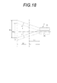
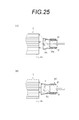
- an optical fiber 201 serving as a strand of a fiber bundle is composed of a core 202 having a high refractive index and a clad having a low refractive index disposed around the core 202.
- Incident light incident from the incident end of the fiber 201 propagates in the optical axis direction while being totally reflected at the boundary between the core 202 and the clad 203 as shown in FIG.
- the light incident on the optical fiber 201 at an incident angle larger than the maximum light receiving angle ⁇ max is transmitted without being totally reflected at the boundary between the core 202 and the clad 203, resulting in a light transmission loss. Therefore, when the luminous flux emitted from the light source is divergent light spreading conically from the light emitting point, the divergent light divergence angle (divergence angle) is within the maximum acceptance angle ⁇ max in order to reduce the optical transmission loss in the optical fiber. Preferably there is.
- the divergence angle of the incident light incident on the light guide of the endoscope from the light source is adjusted in consideration of the maximum light receiving angle ⁇ max of the light guide. Specifically, the divergence angle of incident light is adjusted according to the type of endoscope connected to the light source device (such as the length of the insertion portion and the diameter of the light guide).
- the inventors faced the following new challenges while developing a light source device using a plurality of semiconductor light sources. That is, it has been found that there are differences in the divergence angle of the emitted light flux among the plurality of semiconductor light sources depending on the types and individual differences, and the difference greatly affects the image quality of the observation image.
- the reflection angle ⁇ in the optical fiber is preserved in the light propagation process. Therefore, if the incident angle ⁇ 0 is large, the output angle is large, and if the incident angle ⁇ 0 is small, the output angle is small. Since the divergence angle of the light emitted from the optical fiber is reflected in the irradiation spot diameter of the light irradiated from the illumination window of the endoscope toward the observation object, there is a difference in the divergence angle between the plurality of semiconductor light sources. There is also a difference in the irradiation spot diameter.
- Irradiation spot diameters in the observation object of light are also SD ⁇ and SD ⁇ , respectively.
- white light is generated by mixing blue, green, and red as in the light source device described in Patent Document 2, if there is a difference in the irradiation spot diameters of the respective colors, the overlapping of the irradiation spots is determined. As the mixing ratio of blue, green and red changes, color unevenness occurs. Such color unevenness becomes a problem not only in normal observation but also in special light observation.
- Patent Documents 1 to 3 have any explicit or suggestion about such problems or solutions.
- the random fiber bundle described in Patent Documents 1 and 2 has a function of dispersing the optical fibers corresponding to the semiconductor light sources of the respective colors and uniformizing the light quantity distribution of the respective colors in the cross section of the emitted light beam. Since the difference between the divergence angles of the optical fibers is preserved, the color unevenness caused by the difference between the divergence angles cannot be eliminated.
- Patent Document 3 describes that the divergence angle of light emitted from a light source is adjusted according to the type of endoscope. However, the use of a plurality of semiconductor light sources and the divergence angle of those divergence angles are described. There is no indication or suggestion of the problem that color unevenness occurs due to the difference.
- the present invention has been made in view of the above problems, and its purpose is to prevent color unevenness caused by a difference in divergence angle of each semiconductor light source when a plurality of semiconductor light sources are used in an endoscope light source device. There is to do.
- the light source device of the present invention is a plurality of light sources for supplying light to an endoscope, and includes a plurality of semiconductor light sources that emit light extending in a substantially conical shape from a light emitting point, and the light from the plurality of semiconductor light sources.
- the difference between the divergence angles of the light emitted by the plurality of semiconductor light sources is eliminated in the previous stage of supplying to the endoscope, and the optical path integrating part that integrates the optical paths of the light of each semiconductor light source and the previous stage that is incident on the optical path integrating part.
- a divergence angle correction unit that corrects at least one divergence angle among the plurality of semiconductor light sources is provided.
- the correction amount of the divergence angle correction unit is preferably set so that the divergence angles of the light of each semiconductor light source substantially coincide.
- the plurality of semiconductor light sources include a light emitting element and a phosphor that emits fluorescence when excited by the light of the light emitting element, a first light source that emits mixed light in which the light of the light emitting element and the fluorescence are mixed, and the phosphor It is preferable to include a second light source that emits monochromatic light composed only of light from the light emitting element without being used.
- a laser diode is used as the light emitting element.
- a plurality of semiconductor light sources having different divergence angles have different emission wavelengths, for example. Moreover, it is preferable that the divergence angle correction
- the divergence angle correction unit is a reflection type that corrects the divergence angle by propagating light in the optical axis direction while reflecting light internally.
- the reflection type correction unit is, for example, a columnar body formed of a transparent material, and has side surfaces that are inclined with respect to the optical axis direction so that the thicknesses of the light incident end and the light exit end change, and It is a total reflection type that propagates in the direction of the optical axis by total reflection on the side surface.
- the reflection type correction unit may be a cylindrical body whose inner wall surface is formed as a mirror surface, and may be a mirror reflection type that propagates incident light in the optical axis direction by mirror reflection. The inner wall surface may be inclined with respect to the optical axis.
- the divergence angle correction unit may be a diffusion type that corrects the divergence angle by diffusing incident light inside with a light diffusing material.
- the divergence angle correction unit may be a lens.
- the divergence angle correction unit may be a correction amount fixed type in which the divergence angle correction amount is fixed, or the divergence angle correction unit may be a correction amount variable type in which the divergence angle correction amount can be adjusted.
- the optical path integration unit is a fiber bundle in which a plurality of optical fibers are bundled, and has a branching unit with an incident end branched into a plurality of branches, and guides incident light from each branching unit to one output end.
- a bundle is preferred.
- the correction amount of the divergence angle correction unit is preferably set so that the divergence angle substantially coincides with the maximum light receiving angle of the light guide built in the endoscope.
- the correction amount of the divergence angle correction unit may be set such that the divergence angle exceeds the maximum light receiving angle of the light guide built in the endoscope.
- An endoscope system includes an endoscope and a light source device that supplies light to the endoscope.
- the light source device includes a plurality of light sources for supplying light to the endoscope.
- a plurality of semiconductor light sources that emit light that spreads in a substantially conical shape from a light emitting point, and an optical path integration unit that integrates the optical paths of the light of each semiconductor light source in the previous stage of supplying light from the plurality of semiconductor light sources to the endoscope
- a divergence angle correction that corrects at least one divergence angle of the plurality of semiconductor light sources so that a difference in divergence angles of the light emitted from the plurality of semiconductor light sources is eliminated before the light is incident on the optical path integration unit.
- the present invention when a plurality of semiconductor light sources are used in an endoscope light source device, at least one of the plurality of semiconductor light sources is selected so that a difference in divergence angle of each semiconductor light source is eliminated. Since the divergence angle correction unit for correcting the divergence angle is provided, it is possible to prevent color unevenness due to the difference in divergence angle between the semiconductor light sources.
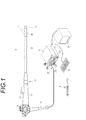
- an endoscope system 10 includes an endoscope 11 that images an observation site in a living body, and an observation image of the observation site based on a signal obtained by the imaging. , A light source device 13 that supplies light to irradiate the observation site to the endoscope 11, and a monitor 14 that displays an observation image.
- the processor device 12 is provided with a console 15 that is an operation input unit such as a keyboard and a mouse.
- the endoscope system 10 includes a normal observation mode for observing an observation site under white light, and a blood vessel information observation mode for observing the properties of blood vessels existing in the observation site using special light. ing.
- the blood vessel information observation mode is a special light observation mode for diagnosing the characteristics of blood vessels such as blood vessel pattern and oxygen saturation, and for distinguishing tumors from good to bad.
- the absorbance to blood hemoglobin is Narrow band light in a high wavelength range is used.
- the blood vessel information observation mode includes a blood vessel enhancement observation mode for displaying a blood vessel enhancement image in which blood vessels are enhanced, and an oxygen saturation observation mode for displaying an oxygen saturation image in which the oxygen saturation of blood hemoglobin is displayed.
- the endoscope 11 includes an insertion portion 16 inserted into a digestive tract of a living body, an operation portion 17 provided at a proximal end portion of the insertion portion 16, and between the operation portion 17, the processor device 12, and the light source device 13. And a universal cord 18 to be connected.
- the insertion portion 16 includes a distal end portion 19, a bending portion 20, and a flexible tube portion 21 that are continuously provided from the distal end.
- the illumination window 22 that irradiates the observation site with illumination light
- the observation window 23 that receives the image light reflected by the observation site, and the observation window 23 are washed.
- An air supply / water supply nozzle 24 for performing air supply / water supply, a forceps outlet 25 for projecting a treatment tool such as a forceps and an electric knife, and the like are provided.
- An imaging element 44 (see FIG. 3) and an imaging optical system are built in the back of the observation window 23.
- the bending portion 20 is composed of a plurality of connected bending pieces, and is bent in the vertical and horizontal directions by operating the angle knob 26 of the operation portion 17. By bending the bending portion 20, the direction of the distal end portion 19 is directed in a desired direction.
- the flexible tube portion 21 is flexible so that it can be inserted into a tortuous duct such as the esophagus or the intestine.
- the insertion unit 16 includes a communication cable that communicates a drive signal for driving the image sensor 44 and an image signal output from the image sensor 44, and a light guide 43 that guides illumination light supplied from the light source device 13 to the illumination window 22. (See FIG. 3) is inserted.
- the operation unit 17 includes a forceps port 27 for inserting a treatment instrument, an air / water supply button for performing air / water supply operation, a release button for taking a still image, and the like. .
- a communication cable and a light guide 43 extending from the insertion portion 16 are inserted through the universal cord 18, and a connector 28 is attached to one end of the processor device 12 and the light source device 13.
- the connector 28 is a composite type connector composed of a communication connector 28a and a light source connector 28b.
- One end of a communication cable is disposed in the communication connector 28a, and the communication connector 28a is detachably connected to the processor device 12.
- the light guide connector 28 b is provided with an incident end of the light guide 43, and the light source connector 28 b is detachably connected to the light source device 13.
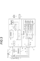
- the light source device 13 includes three types of first to third light source modules 31 to 33 each having a different emission wavelength, and a light source control unit 34 that drives and controls them.
- the light source control unit 34 controls drive timing and synchronization timing of each unit of the light source device 13.
- the first to third light source modules 31 to 33 have laser diodes LD1 to LD3 that respectively emit narrowband light in a specific wavelength range.
- the laser diode LD1 in the blue (B color) region, the laser diode LD1 emits narrowband light N1 having a wavelength region limited to 440 ⁇ 10 nm and a center wavelength of 445 nm, for example.
- the laser diode LD2 In the blue (B color) region, the laser diode LD2 emits narrowband light N2, which is a narrowband light having a wavelength range limited to 410 ⁇ 10 nm and a center wavelength of 405 nm, for example.
- the laser diode LD3 In the blue (B color) region, the laser diode LD3 emits narrowband light N3, which is a narrowband light whose wavelength range is limited to 470 ⁇ 10 nm and whose center wavelength is 473 nm, for example.
- the laser diodes LD1, LD2, and LD3 InGaN-based, InGaNAs-based, and GaNAs-based ones can be used.
- the laser diodes LD1 to LD3 are preferably broad area type laser diodes having a wide stripe width (waveguide width) capable of increasing the output.
- the first light source module 31 is a light source that emits white light for normal observation.
- the first light source module 31 includes a phosphor 36 in addition to the laser diode LD1.
- the phosphor 36 is excited by the 445 nm blue-band narrow-band light N1 emitted from the laser diode LD1, and emits fluorescence FL in a wavelength region extending from the green region to the red region.
- the phosphor 36 absorbs a part of the narrowband light N1 to emit fluorescence FL and transmits the remaining narrowband light N1.
- the narrowband light N1 that passes through the phosphor 36 is diffused by the phosphor 36.
- White light is generated by the transmitted narrow-band light N1 and the excited fluorescence FL.
- the phosphor 36 for example, a YAG-based or BAM (BgMgAl 10 O 17 ) -based phosphor is used.
- Two first light source modules 31 are provided so that the amount of white light increases.
- the second light source module 32 is a light source for blood vessel enhancement observation.
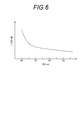
- the absorption coefficient ⁇ a of blood hemoglobin has a wavelength dependence, increases rapidly in the region where the wavelength is 450 nm or less, and has a peak in the vicinity of 405 nm. Yes. Further, although the wavelength is lower than that of 450 nm or less, there is also a peak at wavelengths of 530 nm to 560 nm.
- the observation site is irradiated with light having a wavelength having a large extinction coefficient ⁇ a, the blood vessel has a large absorption, so that an image having a large contrast between the blood vessel and the other portion is obtained.
- the light scattering characteristic of the living tissue is also wavelength-dependent, and the scattering coefficient ⁇ S increases as the wavelength becomes shorter. Scattering affects the depth of light penetration into living tissue. That is, the greater the scattering, the more light that is reflected near the mucosal surface layer of the biological tissue and the less light that reaches the mid-deep layer. Therefore, the shorter the wavelength, the lower the depth of penetration, and the longer the wavelength, the higher the depth of penetration. In view of such light absorption characteristics of hemoglobin and light scattering characteristics of living tissue, the wavelength of light for blood vessel enhancement is selected.
- the 405-nm narrow-band light N2 emitted from the second light source module 32 has a low depth of penetration and is therefore absorbed by the surface blood vessels, and is therefore used as light for emphasizing the surface blood vessels.
- the narrowband light N2 the superficial blood vessel can be depicted with high contrast in the observation image.
- the green component of white light emitted from the first light source module 31 is used as the light for emphasizing the middle deep blood vessel.
- the light absorption coefficient gradually changes in the green region of 530 nm to 560 nm as compared with the blue region of 450 nm or less. It is not required to be. Therefore, as described later, a green component color-separated from white light by the G-color micro color filter of the image sensor 44 is used.
- the third light source module 33 is a light source for oxygen saturation observation.
- an absorption spectrum Hb indicates an absorption spectrum of reduced hemoglobin not bonded to oxygen
- an absorption spectrum HbO2 indicates an absorption spectrum of oxidized hemoglobin bonded to oxygen.
- reduced hemoglobin and oxyhemoglobin have different light absorption characteristics, and a difference occurs in the light absorption coefficient ⁇ a except for the isosbestic point (intersection of each spectrum Hb and HbO 2) showing the same light absorption coefficient ⁇ a. If there is a difference in the extinction coefficient ⁇ a, even if the light having the same light intensity and the same wavelength is irradiated, the reflectance changes if the oxygen saturation changes.
- the oxygen saturation is measured using narrowband light N3 having a wavelength of 473 nm emitted from the third light source module 33 as a wavelength having a difference in the absorption coefficient ⁇ a.
- the light source controller 34 controls turning on / off of the laser diodes LD1 to LD3 and the amount of light through the driver 37. Specifically, the light source controller 34 turns on the laser diodes LD1 to LD3 by applying a drive pulse. Then, by performing PWM control for controlling the duty ratio of the drive pulse, the drive current value is changed to control the light emission amount.
- the control of the drive current value may be PAM control for changing the amplitude of the drive pulse.
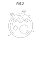
- a branched light guide 41 is provided on the downstream side of the optical path of the first to third light source modules 31 to 33.
- the branching light guide 41 is an optical path integrating unit that integrates the optical paths of the first to third light source modules 31 to 33 into one optical path, as will be described in detail later. Since the light guide 43 of the endoscope 11 has one incident end, each branch light guide 41 supplies light from the first to third light source modules 31 to 33 to the endoscope 11 at each stage. The light paths of the modules 31 to 33 are integrated.
- the branched light guide 41 has branch portions 41a to 41d whose entrance ends are branched into a plurality of portions, and emits light incident from the respective branch portions 41a to 41d from one exit end 41e.
- the two first light source modules 31 are respectively arranged so as to face the incident surfaces of the branch portions 41a and 41b of the branch light guide 41, and the second and third light source modules 32 and 33 are respectively branched portions 41c and 41d. It arrange
- the exit end 41e of the branched light guide 41 is disposed near the receptacle connector 42 to which the connector 28b of the endoscope 11 is connected.
- a homogenizer 50 which will be described later, is provided at the emission end 41e, and the light of the first to third light source modules 31 to 33 incident on the branched light guide 41 is distributed to the connector 28b via the homogenizer 50.
- the light guide 43 of the endoscope 11 is supplied.
- the endoscope 11 includes a light guide 43, an imaging device 44, an analog processing circuit 45 (AFE: Analog Front End), and an imaging control unit 46.
- the light guide 43 is a fiber bundle obtained by bundling a plurality of optical fibers (see reference numeral 201 in FIG. 18), and when the connector 28 is connected to the light source device 13, the incident end of the light guide 43 is the light source device 13. It faces the emission end of the homogenizer 50.
- the exit end of the light guide 43 branches into two at the front stage of the illumination window 22 so that light is guided to the two illumination windows 22.
- an irradiation lens 48 is disposed in the back of the illumination window 22 in the back of the illumination window 22, an irradiation lens 48 is disposed.
- the light supplied from the light source device 13 is guided to the irradiation lens 48 by the light guide 43 and irradiated from the illumination window 22 toward the observation site.
- the irradiation lens 48 is a concave lens, and widens the divergence angle of the light emitted from the light guide 43.
- the illumination light emitted from the illumination window 22 should have a wide divergence angle so that a wide range of the observation site can be irradiated.
- the divergence angle of light emitted from the light guide 43 is determined by the NA (numerical aperture) of the light guide 43, and light having a divergence angle equal to or greater than NA cannot be emitted. By providing the irradiation lens 48, the divergence angle is widened beyond the NA of the light guide 43.
- an objective optical system 51 and an image sensor 44 are arranged in the back of the observation window 23.
- the image light reflected by the observation site enters the objective optical system 51 through the observation window 23 and is imaged on the imaging surface 44 a of the imaging element 44 by the objective optical system 51.
- the imaging device 44 is composed of a CCD image sensor, a CMOS image sensor, or the like, and has an imaging surface 44a in which a plurality of photoelectric conversion elements constituting pixels such as photodiodes are arranged in a matrix.
- the image sensor 44 photoelectrically converts the light received by the imaging surface 44a and accumulates signal charges corresponding to the amount of received light in each pixel.
- the signal charge is converted into a voltage signal by an amplifier and read out.
- the voltage signal is output from the image sensor 44 as an image signal, and the image signal is sent to the AFE 45.
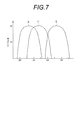
- the image sensor 44 is a color image sensor, and micro-color filters of three colors B, G, and R having spectral characteristics as shown in FIG. 7 are assigned to each pixel on the imaging surface 44a.
- the white light emitted from the first light source module 31 is split into three colors B, G, and R by the micro color filter.
- the arrangement of the micro color filter is, for example, a Bayer arrangement.
- the imaging device 44 performs an accumulation operation for accumulating signal charges and a read operation for reading the accumulated signal charges within an acquisition period of one frame.
- the laser diode LD1 is turned on in accordance with the accumulation timing, and the observation site is irradiated with white light composed of the narrowband light N1 and the fluorescence FL as illumination light. The reflected light enters the image sensor 44.
- the white light is color-separated by a micro color filter
- the B pixel receives reflected light corresponding to the narrowband light N1
- the G pixel in the fluorescent FL receives reflected light corresponding to the R component.
- the image sensor 44 sequentially outputs the image signals B, G, and R for one frame in which the pixel values of the B, G, and R pixels are mixed according to the frame rate in accordance with the readout timing. Such an imaging operation is repeated while the normal observation mode is set.
- the second light source module 32 is turned on in addition to the first light source module 31 in accordance with the accumulation timing.
- the observation site is irradiated with white light (N1 + FL) composed of the narrowband light N1 and the fluorescence FL as illumination light.
- the narrowband light N2 is added to the white light (N1 + FL), and these are irradiated to the observation site as illumination light.
- the illumination light in which the narrow band light N2 is added to the white light is split by the B, G, R micro color filters of the image sensor 44.
- the B pixel receives the narrowband light N2 in addition to the narrowband light N1.
- the G pixel receives the G component of the fluorescence FL.
- the R pixel receives the R component of the fluorescence FL.
- the image sensor 44 sequentially outputs the image signals B, G, and R according to the frame rate in accordance with the readout timing. Such an imaging operation is repeated while the blood vessel enhancement observation mode is set.
- the first light source module 31 is turned on in accordance with the accumulation timing.
- white light N1 + FL
- the first light source module 31 is turned off, the third light source module 33 is turned on, and the narrow-band light N3 is irradiated to the observation site.
- the image sensor 44 sequentially outputs the image signals B, G, and R according to the frame rate in accordance with the readout timing.
- the oxygen saturation observation mode unlike the normal observation mode and the blood vessel enhancement observation mode, white light (N1 + FL) and narrowband light N3 are alternately irradiated, so that the image signal B corresponding to white light in the first frame is used. , G, R are output, and in the next frame, the image signals B, G, R corresponding to the narrowband light N3 are output, and the image signals B, G, R are carried corresponding to each illumination light.
- the information to be changed also changes every other frame. Such an imaging operation is repeated while the blood vessel enhancement observation mode is set.
- the AFE 45 includes a correlated double sampling circuit (CDS), an automatic gain control circuit (AGC), and an analog / digital converter (A / D) (all not shown).
- the CDS performs a correlated double sampling process on the analog image signal from the image sensor 44, and removes noise caused by resetting the signal charge.
- AGC amplifies an image signal from which noise has been removed by CDS.
- the A / D converts the image signal amplified by AGC into a digital image signal having a gradation value corresponding to a predetermined number of bits and inputs the digital image signal to the processor device 12.
- the imaging control unit 46 is connected to the controller 56 in the processor device 12 and inputs a drive signal to the imaging device 44 in synchronization with the base clock signal input from the controller 56.
- the imaging element 44 outputs an image signal to the AFE 45 at a predetermined frame rate based on the drive signal from the imaging control unit 46.
- the processor device 12 includes a DSP (Digital Signal Processor) 57, an image processing unit 58, a frame memory 59, and a display control circuit 60 in addition to the controller 56.
- the controller 56 includes a CPU, a ROM that stores a control program and setting data necessary for control, a RAM that loads the program and functions as a work memory, and the like. To control.
- the DSP 57 acquires an image signal output from the image sensor 44.
- the DSP 57 separates an image signal in which signals corresponding to B, G, and R pixels are mixed into B, G, and R image signals, and performs pixel interpolation processing on the image signals of the respective colors.
- the DSP 57 performs signal processing such as gamma correction and white balance correction on each of the B, G, and R image signals.
- the frame memory 59 stores image data output from the DSP 57 and processed data processed by the image processing unit 58.
- the display control circuit 60 reads the image processed image data from the frame memory 59, converts it into a video signal such as a composite signal or a component signal, and outputs it to the monitor 14.
- the image processing unit 58 performs normal observation based on the image signals B, G, and R color-separated into B, G, and R colors by the DSP 57.
- a display image is generated.
- the display image is output to the monitor 14 as an observation image.
- the image processing unit 58 updates the display image every time the image signals B, G, and R in the frame memory 59 are updated.
- the image processing unit 58 in the blood vessel enhancement observation mode, the image processing unit 58 generates a display image for blood vessel enhancement observation based on the image signals B, G, and R.
- the image signal B in the blood vessel enhancement observation mode includes information on the narrow band light N2 in addition to the B component of white light (including a part of the narrow band light N1 and the fluorescence FL). It is drawn with high contrast. In lesions such as cancer, there is a tendency to increase the density of superficial blood vessels compared to normal tissues, so there is a feature in the blood vessel pattern, so in blood vessel enhancement observation for the purpose of tumor discrimination, It is preferable that the superficial blood vessel is clearly depicted. Further, since the image signal G includes a lot of information about the middle-deep blood vessels, the image signal G is subjected to contour enhancement processing and the like to emphasize the middle-deep blood vessels.
- the display image for blood vessel enhancement observation is generated based on the three color image signals B, G, and R in the same way as for normal observation, so that the observation site can be displayed in full color.
- the image signal B in the mode has a higher blue density than the image signal B in the normal observation mode. For this reason, when a display image for blood vessel enhancement observation is generated, color correction is performed so that the same color as that of the display image for normal observation is obtained.
- the image processing unit 58 generates a display image for blood vessel enhancement observation every time the image signals B, G, and R in the frame memory 59 are updated.
- the image signal B is generated using only two colors of the image signals B and G without using the image signal R, and the image signal B is generated by the B channel and the G channel of the monitor 14.
- a method of displaying the observation region in a pseudo color such as a method of assigning a signal corresponding to the image signal G to the R channel of the monitor 14, may be employed.
- the image processing unit 58 is acquired under the image signals G1 and R1 acquired under white light and the narrowband light N3. Based on the obtained image signal B2, oxygen saturation calculation processing is performed.
- the pixel value of the image signal B2 includes blood volume (concentration) information in addition to oxygen saturation. In order to obtain the oxygen saturation more accurately, it is necessary to separate blood volume information from the pixel value of the image signal B2.
- the image processing unit 58 performs an inter-image calculation with the image signal B using the image signal R showing a high correlation with the blood volume, and separates oxygen saturation and blood volume information.
- the image processing unit 58 collates pixel values at the same position of the image signals B2, G1, and R1, and calculates a signal ratio B / G between the pixel value of the image signal B2 and the pixel value of the image signal G1.
- the signal ratio R / G between the pixel value of the image signal R1 and the pixel value of the image signal G1 is obtained.
- the image signal G1 is used as a reference signal representing the brightness level of the observation region in order to normalize the pixel values of the image signal B2 and the image signal R1.
- the oxygen saturation that is obtained by separating the blood volume information is calculated.
- the full color image generated based on the image signals B1, G1, and R1 is subjected to color conversion in accordance with the calculated oxygen saturation value to generate a display image for oxygen saturation observation.
- the branched light guide 41 provided in the light source device 13 is a fiber bundle in which a plurality of optical fibers are bundled in the same manner as the light guide 43 of the endoscope 11.
- the branched light guide 41 has all the optical fibers bundled together at the exit end 41e, and divides all the optical fibers into four on the way to the incident end, A plurality of branch portions 41a to 41d are formed by bundling.
- the thicknesses of the branch portions 41a and 41b and the branch portions 41c and 41d are changed by changing the number of bundled optical fibers, and the respective diameters are D1 and D2.
- the diameter D1 of the branch portions 41a and 41b is thicker than the diameter D2 of the branch portions 41c and 41d.
- One reason for the difference in thickness is that the first light source module 31 that faces the branch portions 41a and 41b uses the phosphor 36, and therefore the second light source module 32 that does not use the phosphor 36. This is because the diameter of the luminous flux emitted is larger than that of.
- Another reason is that the first light source module 31 emits white light for normal observation, so that a larger amount of light than the second light source modules 32 and 33 for special light observation is secured.
- a homogenizer 50 is provided at the exit end 41e of the branched light guide 41.
- the homogenizer 50 equalizes the light quantity distribution of the light of each color emitted from the first to third light source modules 31 to 33 and emitted from the emission end 41e in the front stage of the light guide 43 of the endoscope 11.
- the homogenizer 50 is formed of a transparent material such as transparent glass and is a columnar body having a circular cross section perpendicular to the optical axis, and totally reflects light incident from the incident end 50a on the inner side surface 50b serving as an interface with air. Then, it propagates in the optical axis direction and exits from the exit end 50c.
- an optical fiber having one end located in each of the regions a to d partitioned by a two-dot chain line at the emission end 41e is allocated to each of the branch portions 41a to 41d.
- the optical fibers corresponding to the branch portions 41a to 41d are locally unevenly distributed at the emission end 41e.
- the light incident from the branch portions 41a to 41d is propagated in the respective optical fibers, and naturally there is no propagation between the optical fibers.
- the emission end 41e white light emitted from the first light source module 31 is emitted from the upper left and upper right areas a and b, and the narrowband light N2 emitted from the second light source module 32 is emitted from the area c, and the area d
- the light of each color is unevenly distributed such that the narrow band light N3 emitted from the third light source module 33 is emitted. Therefore, the light quantity distribution of each color becomes non-uniform in the cross section of the light beam emitted from the emission end 41e.
- the homogenizer 50 propagates light in the direction of the optical axis while totally reflecting the light incident from the end surface of the incident end 50a on the side surface 50b. Therefore, the light incident position in the cross section orthogonal to the optical axis. And the emission position changes. By such an action, the uneven distribution of the light of each color at the exit end 41e of the branched light guide 41 is eliminated, and the light quantity distribution of the light of each color is made uniform in the cross section of the incident light beam incident on the light guide 43.
- the homogenizer 50 and the emission end 41e are integrated by heat-sealing with the end faces abutting each other.
- the first light source module 31 includes a laser module 61, a fluorescent part 62, a single-line optical fiber 63 that guides the light of the laser module 61 to the fluorescent part 62, and a fluorescent part 62.
- tip of this is provided.
- the laser module 61 includes a light emitting element 66 having a laser diode LD1 and a case 67 that houses the light emitting element 66.
- the case 67 is provided with a connecting portion 67a that connects one end of the optical fiber 63. This is a so-called receptacle-type module in which a condensing lens 68 is incorporated.
- the light emitting element 66 is obtained by attaching a laser diode LD1 as a semiconductor chip to one surface of a disc-shaped stem 66a serving as a support, and covering the laser diode LD1 with a resin-made cylindrical transparent cap 66b.
- a lead wire 66c extends from the back surface of the stem 66a.
- the laser diode LD1 is formed by joining a P layer made of a P-type semiconductor and an N layer made of an N-type semiconductor with an active layer interposed therebetween, and emits light from the active layer by laser oscillation.
- Laser light has high straightness, but its beam shape is divergent light that spreads in a substantially conical shape from the emission point.
- the laser light is condensed at the incident end of the optical fiber 63 by the condenser lens 68.
- the outgoing end of the optical fiber 63 is connected to the fluorescent part 62.
- the fluorescent part 62 is obtained by filling a fluorescent material 36 in a cylindrical protective case 62a having a light shielding property.
- An insertion hole into which the optical fiber 63 is inserted is formed at the center of the phosphor 36.
- the optical fiber 63 is inserted into the phosphor 36 with a connection ferrule (not shown) attached to its end.
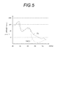
- the phosphor 36 is obtained by dispersing and solidifying a powdery fluorescent material in a binder made of a resin material. Since the fluorescent material is dispersed, the emission point of the excited fluorescence FL is the entire emission end face of the phosphor 36. Further, since the laser light transmitted through the phosphor 36 is also diffused in the phosphor 36 by the light diffusing action of the binder, the entire area of the emission end face becomes a light emitting point. Like the laser diode LD1, the light emitted from the phosphor 36 is a diverging light that spreads in a substantially conical shape from the light emitting point. However, compared with the laser diode LD1, the area of the light emitting point and the divergence angle of the light beam are large.
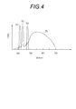
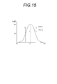
- the divergence angle of the light beam is defined using, for example, the half-value width in the light intensity distribution of the cross section orthogonal to the optical axis of the light beam.
- the light intensity distribution of a light beam that spreads in a substantially conical shape from a light emitting point like a laser diode is represented by a graph in which the horizontal axis indicates the radiation angle and the vertical axis indicates the light intensity, as shown in FIG.
- the peak (max) is at (0 °), and a mountain-shaped distribution that decreases toward the periphery.
- the full width at half maximum is the width between two points where the light intensity shows a half value (harf) with respect to the peak value (max) in the light intensity distribution, half of which is half width (half width) at half maximum, HWHM).
- the divergence angle is larger as the half width is larger, and the divergence angle is smaller as the half width is smaller.
- a divergence angle correction unit 64 that corrects the divergence angle of diverging light emitted from the emission end face 36a of the phosphor 36 is provided in front of the fluorescent unit 62.
- the divergence angle correction unit 64 has a cylindrical shape made of a light-shielding material, and regulates the spread of divergent light emitted from the phosphor 36 to reduce the divergence angle.
- amendment part 64 forms the mirror surface by coating a reflecting material on the inner wall surface 64a, and is a specular reflection type which functions as a reflector. Therefore, the light propagates in the optical axis direction while being specularly reflected by the inner wall surface 64a. Since the light absorption is reduced by making the inner wall surface 64a a mirror surface, there is little light transmission loss.
- the divergence angle of the light emitted from the phosphor 36 is regulated to an angle ⁇ by the divergence angle correction unit 64.
- the angle ⁇ indicates the half width at half maximum (HWHM), and the full width at half maximum (FWHM) is 2 ⁇ .
- the length of the divergence angle correction unit 64 in the optical axis direction, the inclination angle of the reflection surface (inner wall surface 64a) with respect to the optical axis, and the distance between the tip of the divergence angle correction unit 64 and the incident end surfaces of the branch portions 41a and 41b are It is set in consideration of the NA (numerical aperture) of the optical fiber constituting the light guide 43 of the endoscope 11 and the thickness (diameter D1) of the branch portions 41a and 41b. Specifically, the length, inclination angle, and interval of the divergence angle correction unit 64 are substantially the same as the maximum light reception angle ⁇ max (see FIG.
- the divergence angle ⁇ indicated by the half width at half maximum corresponds to the NA (numerical aperture) of the optical fiber. It is set so that the angles coincide with each other and the spot diameter of the incident light beam incident on the branch portions 41a and 41b substantially matches the diameter D1 of the branch portions 41a and 41b.
- the divergence angle ⁇ is within the maximum light receiving angle ⁇ max (see FIG. 26)
- light incident on the optical fiber satisfies the total reflection condition, so that there is little light transmission loss in the optical fiber.
- the divergence angle ⁇ the light distribution angle of the illumination light emitted from the illumination window 22 of the endoscope 11 is increased, and a wider region of the observation site can be irradiated.
- the spot diameter to the diameter D1 of the branch portion 41a, light can be incident on many of the plurality of optical fibers constituting the branch portions 41a and 41b, so that the light transmission efficiency is also improved.
- the spot diameter is made larger than the diameter D1 of the branch portion 41a, light leakage that does not enter the branch portions 41a and 41b occurs.
- the spot diameter is adjusted to the diameter D1 of the branching portion 41a, there is little light transmission loss due to light leakage.
- the second light source module 32 includes a light emitting element 71 and a divergence angle correction unit 72.
- the light emitting element 71 includes a laser diode LD2, and the form thereof is the same as that of the light emitting element 66 of the first light source module 31.
- the divergence angle correction unit 72 is a rod-type light guide made of a transparent material and made of a substantially conical columnar body, and is also called a light pipe or the like. Similar to the homogenizer 50, the divergence angle correction unit 72 is a total reflection type that propagates in the optical axis direction while totally reflecting light incident from the incident end 72a on the side surface 72b and is emitted from the output end 72c. For example, the divergence angle correction unit 72 is integrated by heat-sealing the incident end 72 a and the tip of the light emitting element 71.
- the divergence angle correction unit 72 has a tapered shape in which the side surface 72b is inclined with respect to the optical axis so that the thickness of the output end 72c is smaller than the thickness of the incident end 72a. Therefore, as shown in FIG. 17, when the reflected light is repeatedly reflected on the side surface 72 b so that the incident light has a second reflection angle ⁇ 2 smaller than the first reflection angle ⁇ 1, the reflection angle ⁇ gradually decreases. It will become. A decrease in the reflection angle ⁇ means that the divergence angle increases. Due to the action of the divergence angle correction unit 72, the divergence angle ⁇ 1 of the light emitted from the laser diode LD2 is expanded to the divergence angle ⁇ 2.
- the length of the divergence angle correction unit 72 in the optical axis direction, the inclination angle of the reflecting surface with respect to the optical axis, and the distance between the tip of the divergence angle correction unit 64 and the incident end surface of the branching portion 41 c are determined as the divergence angle of the first light source module 31.
- the NA is set in consideration of the NA (numerical aperture) of the optical fiber constituting the light guide 43 of the endoscope 11 and the thickness (diameter D2) of the branching unit 41c.
- the length, inclination angle, and interval of the divergence angle correction unit 72 are substantially the same as the maximum light reception angle ⁇ max (see FIG.
- the divergence angle ⁇ 2 indicated by the half width at half maximum corresponds to the NA (numerical aperture) of the optical fiber. It is set so that the angle coincides and the spot diameter of the incident light beam incident on the branching portion 41c substantially matches the diameter D2 of the branching portion 41c.
- the divergence angle correction unit 64 of the first light source module 31 if the divergence angle ⁇ 2 is within the maximum light receiving angle ⁇ max (see FIG. 26), the light incident on the optical fiber satisfies the total reflection condition. Less optical transmission loss in the fiber. Further, by maximizing the divergence angle ⁇ 2, the light distribution angle of the illumination light emitted from the illumination window 22 of the endoscope 11 is increased, and a wider region of the observation site can be irradiated. Further, by adjusting the spot diameter to the diameter of the branch portion 41c, light can be incident on many of the plurality of optical fibers constituting the branch portion 41c, so that the light transmission efficiency is also improved.
- the third light source module 33 is the same as the second light source module 32 except that a light emitting element 76 having a laser diode LD3 (see FIG. 10) is provided instead of the light emitting element 71 of the second light source module 32. The description is omitted because it is similar.
- the divergence angle of the light emitting element 76 of the third light source module 33 is also enlarged by the divergence angle correction unit 72 so as to substantially match the maximum light receiving angle ⁇ max of the optical fiber constituting the branching portion 41d.
- the second light source module 32 and the third light source module 33 are light sources that do not use the phosphor 36. Therefore, there is no great difference in the divergence angle between the modules 32 and 33. However, when there is a difference in the divergence angle between the light emitting elements 66 and 71, the inclination angle of the side surface 72b of each divergence angle correction unit 72 is changed so that the difference between the two is eliminated, etc. Each correction amount is set.
- the endoscope 11 When performing an endoscopic diagnosis, the endoscope 11 is connected to the processor device 12 and the light source device 13, the processor device 12 and the light source device 13 are turned on, and the electronic endoscope system 10 is activated.
- the insertion part 16 of the endoscope 11 is inserted into the subject's digestive tract, and observation in the digestive tract is started.
- the first light source module 31 is turned on, and the white light in which the narrow band light N1 emitted from the laser diode LD1 and the fluorescence FL emitted from the phosphor 36 are mixed. Is irradiated to the observation site.
- the white light (N1 + FL) emitted from the phosphor 36 is corrected by the divergence angle correction unit 64 so that the divergence angle matches the NA (numerical aperture) of the optical fiber. Therefore, there is little light transmission loss in the optical fiber. Moreover, since the divergence angle is maximized within the NA of the optical fiber, a wide range of the observation site can be irradiated. Further, since the spot diameter of the light beam incident on the branch portions 41a and 41b is set to match the diameter D1 of the branch portions 41a and 41b, the light transmission loss is small and the light transmission efficiency is good.
- the corrected white light is incident on the branch portions 41a and 41b of the branch light guide 41 and guided to the output end 41e.
- the light is incident on the homogenizer 50.
- the white light guided from the branch portions 41a and 41b is unevenly distributed on the end face of the emission end 41e.
- the light quantity distribution is made uniform by the homogenizer 50.
- white light having no unevenness in the amount of light in the cross section of the light beam enters the light guide 43 of the endoscope 11.
- White light is irradiated from the illumination window 22 to the observation site in the digestive tract through the light guide 43.
- the observation site is imaged by the imaging device 44 during the irradiation with white light (N1 + FL), and B, G, and R image signals are generated by the DSP 57.
- the image processing unit 58 In the normal observation mode, the image processing unit 58 generates a display image for normal observation based on the B, G, and R image signals.
- the display control circuit 60 converts the display image for normal observation into a video signal and displays it on the monitor 14. Such processing is repeated in the normal observation mode.
- a mode switching operation is performed by the console 15, and the processor device 12 is set to the blood vessel enhancement observation mode.
- the second light source module 32 is turned on in addition to the first light source module 31, and white light (N1 + FL) and narrow band light N2 are irradiated to the observation site. Is done.
- the narrowband light N2 emitted from the laser diode LD2 is adjusted by the divergence angle correction unit 72 so that the divergence angle matches the NA (numerical aperture) of the optical fiber, that is, the maximum light receiving angle ⁇ max (see FIG. 26). ) Is corrected to almost coincide with.
- the first light source module 31 is also corrected by the divergence angle correction unit 64 so that the divergence angle matches the NA of the optical fiber.
- the divergence angle correction unit 72 is provided so that the divergence angle is matched with the NA of the optical fiber, and further, the effect of matching the spot diameter of the narrowband light N2 with the branching portion 41c is the first light source.
- the light transmission loss can be reduced and the light transmission efficiency can be improved.
- the corrected white light and narrowband light N2 enter the branch portions 41a, 41b and 41c of the branch light guide 41, are guided to the exit end 41e, and enter the homogenizer 50, respectively.
- the white light and the narrow-band light N2 are supplied to the light guide 43 of the endoscope 11 after the light quantity distribution is made uniform by the homogenizer 50.
- the white light and the narrow band light N2 are irradiated from the illumination window 22 to the observation site in the digestive tract through the light guide 43.
- the observation site is imaged by the imaging device 44 during irradiation with white light (N1 + FL) and narrowband light N2, and images of B, G, and R are obtained by the DSP 57.
- a signal is generated.
- the image processing unit 58 generates a display image for blood vessel enhancement observation based on the B, G, and R image signals.
- the display control circuit 60 converts a display image for blood vessel enhancement observation into a video signal and displays it on the monitor 14. Such processing is repeated in the blood vessel enhancement observation mode.
- the image signal B includes the narrowband light N2 in addition to the B component of white light, the superficial blood vessels are depicted with high contrast in the observation image.
- the first and second light source modules 31 and 32 having different divergence angles are used.
- the divergence angles of the light source modules 31 and 32 are substantially matched by the divergence angle correction units 64 and 72. Therefore, there is no color unevenness caused by the difference in divergence angle between the light source modules 31 and 32.
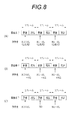
- the light incident on the branched light guide 41 is propagated in the optical axis direction by repeating total reflection in the branched light guide 41, the homogenizer 50, and the light guide 43 of the endoscope 11. Since the reflection angle in total reflection is preserved in the process, the exit angle at the exit end of the light guide 43 depends on the incident angle incident on the branched light guide 41.
- the divergence angles ⁇ at the time of emission from the light source are substantially the same.
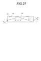
- the irradiation spot diameters SD ⁇ and SD ⁇ at the observation site also almost match. Therefore, as shown in FIG. 28, compared with the prior art in which the divergence angle is not corrected, there are more portions where the irradiation spots of the white light and the narrowband light N2 overlap each other.
- the white light and the narrow-band light N2 are almost uniformly mixed in the entire illumination area, thereby eliminating color unevenness. If there is a difference in the divergence angle, the difference between the irradiation spot diameters SD ⁇ and SD ⁇ increases as the observation distance L becomes longer (Lf than Ln). Therefore, the present invention is particularly effective when the observation distance L is long.
- the first light source module 31 and the third light source module 33 are alternately turned on every frame, and white light (N1 + FL) and narrowband light N3 Alternately irradiate the observation site.
- the first light source module 31 is corrected by the divergence angle correction unit 64 so that the divergence angle matches the NA of the optical fiber.
- the narrowband light N3 emitted from the laser diode LD3 is corrected for the divergence angle similarly to the narrowband light N2.
- the divergence angle is corrected by the unit 72 so as to match the NA of the optical fiber. The effect of this is as described in the normal observation mode and the blood vessel enhancement observation mode.
- the corrected white light and narrowband light N3 enter the branch portions 41a, 41b, and 41d of the branch light guide 41 at each irradiation timing, are guided to the exit end 41e, and enter the homogenizer 50.
- the white light and the narrowband light N3 are supplied to the light guide 43 of the endoscope 11 after the light amount distribution is uniformized by the homogenizer 50.
- the white light and the narrow band light N3 are sequentially irradiated from the illumination window 22 to the observation site in the digestive tract through the light guide 43.
- the image sensor 44 sequentially outputs image signals corresponding to white light (N1 + FL) and narrowband light N3 to the DSP 57.
- the DSP 57 generates an image signal of each color of B1, G1, and R1 based on the image signal acquired under the white light, and generates an image signal of B2 based on the image signal acquired under the narrowband light N3. Is generated.
- the image processing unit 58 calculates the oxygen saturation with the blood volume information separated by performing an inter-image calculation of the image signals B2, G1, and R1. Then, the full color image generated based on the image signals B1, G1, and R1 is subjected to color conversion in accordance with the calculated oxygen saturation value to generate a display image for oxygen saturation observation.
- the first and third light source modules 31 and 33 having different divergence angles are used as in the blood vessel enhancement observation mode, but each of the light source modules 31 and 33 has a divergence angle correction unit 64. , 72 so that the respective divergence angles are substantially matched, there is no color unevenness due to the difference between the divergence angles of the light source modules 31, 33.
- the image signals corresponding to the white light and the narrowband light N3 are acquired in a frame sequential manner, but the inter-image calculation is performed based on the respective image signals. By eliminating the color unevenness between the white light and the narrow band light N3, the reliability of the inter-image calculation is also improved.
- a light source that uses the phosphor 36 and a light source that does not use the phosphor 36 since the difference in divergence angle is large, the present invention for correcting the divergence angle is particularly effective. Further, since a laser diode that emits light having high directivity is used as the light emitting element, the difference in divergence angle tends to be larger than that in the case of using an LED, so that the necessity is particularly high.
- the divergence angles of the first to third light source modules 31 to 33 are corrected and substantially matched to each other.
- substantially match includes a case where there is a difference in a range of ⁇ about 10% in addition to a case where they completely match.
- a preferable range as an allowable range of the difference in divergence angle of each light source is ⁇ about 5%.
- the divergence angles after correction do not have to substantially coincide as in the case where the difference in divergence angle after correction exceeds about ⁇ 10%.
- the divergence angle before correction is provided. It is sufficient that the difference between the two is reduced. This is because if the difference in divergence angle is reduced after correction compared to before correction, the effect of improving color unevenness can be expected.
- the corrected divergence angles of the first to third light source modules 31 to 33 are described as being substantially the same as the maximum light receiving angle ⁇ max of the optical fiber (see FIG. 26).
- the case where there is a perfect match the case where there is a difference in the range of ⁇ about 10% is included.
- a preferable range as an allowable range is ⁇ about 5%.
- an angle exceeding the maximum light receiving angle ⁇ max of the optical fiber may be set. In this way, light leakage that does not enter the optical fiber and light that does not propagate within the optical fiber because it does not satisfy the total reflection condition even if incident are generated, so that the divergence angle is less than the maximum light receiving angle ⁇ max.
- the transmission loss increases, the incident angles of incident light incident on the optical fiber can be made uniform between the first to third light source modules 31 to 33, so that color unevenness can be eliminated.
- the light source modules 31 to 33 may be adjusted so that the corrected divergence angle exceeds the maximum light receiving angle ⁇ max. Therefore, compared with the case where the corrected divergence angles are substantially matched, the adjustment accuracy of the correction amount of the divergence angle correction unit can be lowered, which is effective for cost reduction.
- the divergence angle correction unit is provided in all of the first to third light source modules 31 to 33. However, at least one of the first to third light source modules 31 to 33 is provided. What is necessary is just to be provided. For example, when two types of light source modules having different divergence angles are used, a divergence angle correction unit may be provided only on one side to reduce the difference from the other divergence angle. However, if a divergence angle correction unit is provided for each of the light source modules 31 to 33 as in the above example, the correction amount of each divergence angle can be set, so that the degree of freedom in setting the correction amount is widened. Easy to design.
- the divergence angle correction unit 64 of the first light source module 31 functions as a reflector with the inner wall surface 64a as a mirror surface, but the inner wall surface 64a may not be a mirror surface. This is because it is possible to reduce the divergence angle even if it is not a mirror surface. Of course, if the mirror surface is not used, the light absorption at the inner wall surface 64a increases and the light transmission loss increases. Therefore, it is preferable to use a mirror surface as in the above example.
- the divergence angle correction unit for reducing the divergence angle may not be cylindrical, and may be, for example, a form of the divergence angle correction unit 82 provided in the first light source module 81 shown in FIG.
- the first light source module 81 is the same as the first light source module 31 except that a divergence angle correction unit 82 is provided instead of the divergence angle correction unit 64.
- the divergence angle correction unit 82 of the first light source module 81 is a rod-type light guide formed of a transparent material, like the divergence angle correction unit 72 of the second light source module 32 described above. Contrary to the divergence angle correction unit 72, the divergence angle correction unit 82 has a tapered shape in which the side surface 82b is inclined with respect to the optical axis so that the thickness of the output end 82c is larger than the thickness of the incident end 82a. It has become. For this reason, when reflection is repeated on the side surface 82b so that the incident light has a second reflection angle ⁇ 2 larger than the first reflection angle ⁇ 1, the reflection angle ⁇ gradually increases. An increase in the reflection angle ⁇ means that the divergence angle is reduced. The divergence angle ⁇ of the light emitted from the fluorescent part 62 is reduced by the action of the divergence angle correction unit 82.
- the divergence angle correction unit 82 has a greater effect of reducing the divergence angle because the number of reflections on the side surface 82b increases as the length in the optical axis direction increases. Further, the larger the inclination angle of the side surface 82b, the greater the effect of reducing the divergence angle by one reflection.
- the type and number of light source modules are not limited to the above example, and can be changed as appropriate.
- a plurality of light source modules 83 and 84 may be used to generate white light.
- the light source module 83 is the same as the first light source module 31 except for the fluorescent part 85.
- the fluorescent part 85 includes a phosphor that emits green (G) fluorescence when excited by the blue (B) narrow-band light N1 emitted from the light emitting element 66.
- the light source module 84 includes a light emitting element 87 that emits red (R).
- the light source modules 83 and 84 are turned on simultaneously.
- the B and G light emitted from the light source module 83 and the R light emitted from the light source module 84 are incident on the branch portions 86a and 86b of the respective branch light guides 86 and guided to the emission end 86e.
- white light is generated by being mixed by the homogenizer 50.
- the light source modules 83 and 84 are provided with divergence angle correction units 64 and 72, respectively, and are corrected so that the difference in divergence angle is eliminated. Therefore, color unevenness in the display image for normal observation is reduced. Further, by providing a light source module that emits red as in this example, it is possible to independently increase or decrease the red component occupying white light, and to enhance the color rendering of white light.
- the light source modules 32 and 33 for observing blood vessel information are respectively arranged on one side facing the branch portions 86c and 86b. Further, as an example of generating white light with light from a plurality of light source modules, three light source modules that respectively emit B, G, and R light may be used.
- the example shown in FIG. 22 is an example in which the divergence angle correction unit 91 of the light source module 89 for observing blood vessel information is composed of a light diffusing material 92 and a reflector 93.
- the light source module 89 includes light emitting elements 71 and 76 that emit narrow band lights N2 and N3, respectively. Light emitted from the light emitting elements 71 and 76 is guided to the divergence angle correction unit 91 by the optical fiber 95.
- the optical fiber 95 is a branching fiber with an incident end branched into two branches, and the branching portions are combined by a coupler and combined into one output end.
- Narrow band lights N2 and N3 from the light emitting elements 71 and 76 are guided by the optical fiber 95, enter the light diffusion material 92, and are diffused. After the divergence angle is widened by diffusion, it is narrowed by the reflector 93. By such correction of the divergence angle, the difference between the divergence angles of the two light source modules 31 and the light source module 89 is eliminated. The light from the light source modules 31 and 89 is incident on the incident ends 96 a to 96 c of the branched light guide 96 and guided.
- the light source module 97 is obtained by replacing the divergence angle correction unit 64 of the light source module 31 (see FIGS. 13 and 14) with a divergence angle correction unit 98 made of a convex lens.
- the divergence angle correction unit 98 reduces the divergence angle of the light emitted from the fluorescent unit 62 by the condensing function of the convex lens.
- the divergence angle correction unit 72 of the light source modules 31 and 32 is changed to a divergence angle correction unit 101 made of a concave lens.
- the divergence angle correction unit 98 expands the divergence angle of the light emitted from the light emitting elements 71 and 76 by the divergence action of the concave lens.
- Patent Documents 1 and 2 have been described. May be used. If a random fiber bundle is used, the light quantity distribution can be made uniform without using the homogenizer 50. Of course, it is considered that the use of the homogenizer 50 has a greater effect of making the light quantity distribution uniform. In addition, in order to make the light quantity distribution uniform in the random fiber bundle, it is necessary to arrange the optical fibers at each branching portion to be evenly distributed at the emission end, which may be troublesome to manufacture. is there. Therefore, also from the viewpoint of reducing the manufacturing cost, it is preferable to use a combination of a branched light guide and a homogenizer as in this example.
- the optical path integration unit may be other than the fiber bundle.
- a rod-type light guide 103 may be used.
- the example shown in FIG. 24 is obtained by replacing the branched light guide 41 and the homogenizer 50 of the example shown in FIG. 23 with a rod-type light guide 103, and the light source is the same as in FIG.
- the rod-type light guide 103 is a columnar body made of a transparent material, like the homogenizer 50 and the divergence angle correction unit 72, and propagates light in the optical axis direction by totally reflecting incident light on the side surface 103b. It is a guide. Due to the light mixing action of the rod-type light guide 103, the light paths of the light source modules 97 to 99 are integrated.
- the rod-type light guide 103 has a tapered shape in which the side surface 103b is inclined with respect to the optical axis so that the exit end is narrower than the entrance end.
- a large area can be secured at the incident end 103a where the plurality of light source modules 97 to 99 are arranged to face each other, and the diameter of the emission end 103c can be matched with the diameter of the light guide 43 of the endoscope 11. it can.
- the rod-shaped light guide 103 that functions as the optical path integrating unit has such a tapered shape, as described for the divergence angle correction unit 72 (see FIG. 17), an effect of expanding the divergence angle occurs. Therefore, the correction amounts of the divergence angle correction units 98 and 101 of the light source modules 97 to 99 are set in consideration of the divergence angle expansion effect of the rod type light guide 103.
- a combination of a dichroic mirror that selectively transmits or reflects light of a specific wavelength may be used in addition to the branched light guide and the rod type light guide.
- the dichroic mirror is disposed on the optical path of each light source module.
- Each dichroic mirror is selected corresponding to the wavelength of light emitted by each light source module.
- the divergence angle correction unit 106 is a cylindrical reflector, like the divergence angle correction unit 64.
- the divergence angle correction unit 106 is attached to the protective case 107 so as to be movable in the optical axis direction.
- the divergence angle correction unit 106 is formed with a screw that engages with the protective case 107 of the phosphor 36 at the rear end portion 106a, and moves in the optical axis direction by rotating the divergence angle correction unit 106 around the optical axis. To do.
- the divergence angle correction unit 106 when the position of the divergence angle correction unit 106 is moved forward from the initial position (divergence angle ⁇ 1) shown in FIG. 25A to the position shown in FIG. 25B, the divergence angle is reduced to ⁇ 2. In addition, the correction amount of the divergence angle is adjusted.
- the correction amount is variable, the divergence angle can be finely adjusted after product assembly, making setup and maintenance easy.
- the correction amount may be adjusted electrically by using an actuator.
- a light source that emits diagnostic light or therapeutic light for performing PDD (photodynamic diagnosis) or PDT (photodynamic therapy) is used as a special light source, when high energy light is required, By adjusting the correction amount electrically during the inspection, it is possible to reduce the divergence angle as necessary and generate light with high energy per unit area.
- a plurality of semiconductor light sources having different divergence angles such as a first light source module 31 that emits white light and a second light source module 32 that emits narrow-band light N1
- light sources having different emission wavelengths light emission
- light sources having different colors have been described as examples, light sources having the same emission wavelength may be used although there are differences in divergence angles. For example, both emit white light, but only the divergence angle differs depending on the type of light emitting element and phosphor and individual differences. When the emission wavelengths are the same, unevenness in the amount of light occurs due to the difference in divergence angle.
- one of them may be a plurality of light sources having different spectral spectra such that the blue component is relatively small and the red component is relatively large.
- color unevenness may occur due to the overlapping of the light irradiation spots of the light sources.
- the difference in divergence angle is considered to be larger when a plurality of semiconductor light sources having different emission wavelengths are used compared to the case where the emission wavelengths are the same. Therefore, the present invention is particularly necessary when a plurality of semiconductor light sources having different emission wavelengths are used, such as a light source device corresponding to the blood vessel information observation function and a light source device using a plurality of color light emitting elements to generate white light. Is expensive.
- the meaning that the emission wavelengths are different includes the case where the wavelength ranges of the light emitted by the two semiconductor light sources do not completely overlap and the case where they do not overlap partially.
- the laser diode is described as an example of the semiconductor light source, but another semiconductor light source such as an LED may be used.
- the present invention can be applied to other types of endoscope systems such as a system including an ultrasonic endoscope in which an imaging element and an ultrasonic transducer are built in a distal end portion and a processor device that performs image processing. it can.
Landscapes
- Physics & Mathematics (AREA)
- Health & Medical Sciences (AREA)
- Life Sciences & Earth Sciences (AREA)
- Optics & Photonics (AREA)
- Surgery (AREA)
- Engineering & Computer Science (AREA)
- Heart & Thoracic Surgery (AREA)
- Animal Behavior & Ethology (AREA)
- Radiology & Medical Imaging (AREA)
- Nuclear Medicine, Radiotherapy & Molecular Imaging (AREA)
- Biophysics (AREA)
- Biomedical Technology (AREA)
- General Physics & Mathematics (AREA)
- Medical Informatics (AREA)
- Molecular Biology (AREA)
- Pathology (AREA)
- General Health & Medical Sciences (AREA)
- Public Health (AREA)
- Veterinary Medicine (AREA)
- Microelectronics & Electronic Packaging (AREA)
- Astronomy & Astrophysics (AREA)
- Endoscopes (AREA)
- Microscoopes, Condenser (AREA)
- Instruments For Viewing The Inside Of Hollow Bodies (AREA)
Applications Claiming Priority (2)
| Application Number | Priority Date | Filing Date | Title |
|---|---|---|---|
| JP2012-067175 | 2012-03-23 | ||
| JP2012067175A JP2013198547A (ja) | 2012-03-23 | 2012-03-23 | 光源装置及び内視鏡システム |
Publications (1)
| Publication Number | Publication Date |
|---|---|
| WO2013140961A1 true WO2013140961A1 (fr) | 2013-09-26 |
Family
ID=49222424
Family Applications (1)
| Application Number | Title | Priority Date | Filing Date |
|---|---|---|---|
| PCT/JP2013/054974 Ceased WO2013140961A1 (fr) | 2012-03-23 | 2013-02-26 | Dispositif de source de lumière et système endoscopique |
Country Status (2)
| Country | Link |
|---|---|
| JP (1) | JP2013198547A (fr) |
| WO (1) | WO2013140961A1 (fr) |
Cited By (4)
| Publication number | Priority date | Publication date | Assignee | Title |
|---|---|---|---|---|
| JP2016081870A (ja) * | 2014-10-22 | 2016-05-16 | 三菱電機エンジニアリング株式会社 | レーザ照明装置 |
| WO2018210735A1 (fr) * | 2017-05-16 | 2018-11-22 | Philips Lighting Holding B.V. | Mélange de couleurs dans une source de lumière laser |
| EP3273838A4 (fr) * | 2015-03-24 | 2018-12-05 | HOYA Corporation | Système optique de source lumineuse et dispositif de source lumineuse |
| US11712158B2 (en) | 2018-07-04 | 2023-08-01 | Olympus Corporation | Optical fiber bundle manufacturing apparatus, light guide, endoscope having light guide, and method of manufacturing optical fiber bundle |
Families Citing this family (9)
| Publication number | Priority date | Publication date | Assignee | Title |
|---|---|---|---|---|
| JP6177144B2 (ja) * | 2014-01-20 | 2017-08-09 | 三菱電機株式会社 | 広がり角均一化装置 |
| WO2016103411A1 (fr) * | 2014-12-25 | 2016-06-30 | オリンパス株式会社 | Dispositif source de lumière |
| WO2017078085A1 (fr) * | 2015-11-02 | 2017-05-11 | Hoya株式会社 | Système d'endoscope et dispositif d'analyse |
| DE112017004301T5 (de) * | 2016-08-31 | 2019-05-23 | Hoya Corporation | Endoskoplichtquellenvorrichtung, Endoskop und Endoskopsystem |
| KR101853090B1 (ko) * | 2016-10-13 | 2018-04-27 | (주) 굿피앤씨 | 광 도파로 집광용 엘이디 광원 장치 |
| JP6485656B2 (ja) * | 2017-04-25 | 2019-03-20 | パナソニックIpマネジメント株式会社 | 照明導光装置及び内視鏡装置 |
| JP2021112219A (ja) * | 2018-04-11 | 2021-08-05 | ソニーグループ株式会社 | 医療用システム、医療用光源装置及び医療用光源装置における方法 |
| JP2020062326A (ja) * | 2018-10-19 | 2020-04-23 | ソニー株式会社 | 医療用システム、ライトガイド及び光の合波方法 |
| US20250098951A1 (en) * | 2023-09-27 | 2025-03-27 | Olympus Corporation | Light source device for endoscope |
Citations (7)
| Publication number | Priority date | Publication date | Assignee | Title |
|---|---|---|---|---|
| JPS63249811A (ja) * | 1987-04-06 | 1988-10-17 | Olympus Optical Co Ltd | 照明光学装置 |
| JPH0424709U (fr) * | 1990-06-19 | 1992-02-27 | ||
| JP2001307523A (ja) * | 2000-04-19 | 2001-11-02 | Mitsubishi Rayon Co Ltd | 照明装置 |
| JP2002365488A (ja) * | 2001-06-04 | 2002-12-18 | Kyoto Denkiki Kk | 光源装置 |
| JP2003090939A (ja) * | 2001-09-19 | 2003-03-28 | Matsushita Electric Works Ltd | 照明装置 |
| JP2011033958A (ja) * | 2009-08-05 | 2011-02-17 | Media Technology:Kk | 光源装置 |
| JP2011041758A (ja) * | 2009-08-24 | 2011-03-03 | Olympus Medical Systems Corp | 医療機器 |
Family Cites Families (2)
| Publication number | Priority date | Publication date | Assignee | Title |
|---|---|---|---|---|
| JPH10161041A (ja) * | 1996-11-26 | 1998-06-19 | Fuji Photo Film Co Ltd | 内視鏡用光源装置 |
| JP2009045358A (ja) * | 2007-08-22 | 2009-03-05 | Olympus Corp | 撮像装置 |
-
2012
- 2012-03-23 JP JP2012067175A patent/JP2013198547A/ja not_active Abandoned
-
2013
- 2013-02-26 WO PCT/JP2013/054974 patent/WO2013140961A1/fr not_active Ceased
Patent Citations (7)
| Publication number | Priority date | Publication date | Assignee | Title |
|---|---|---|---|---|
| JPS63249811A (ja) * | 1987-04-06 | 1988-10-17 | Olympus Optical Co Ltd | 照明光学装置 |
| JPH0424709U (fr) * | 1990-06-19 | 1992-02-27 | ||
| JP2001307523A (ja) * | 2000-04-19 | 2001-11-02 | Mitsubishi Rayon Co Ltd | 照明装置 |
| JP2002365488A (ja) * | 2001-06-04 | 2002-12-18 | Kyoto Denkiki Kk | 光源装置 |
| JP2003090939A (ja) * | 2001-09-19 | 2003-03-28 | Matsushita Electric Works Ltd | 照明装置 |
| JP2011033958A (ja) * | 2009-08-05 | 2011-02-17 | Media Technology:Kk | 光源装置 |
| JP2011041758A (ja) * | 2009-08-24 | 2011-03-03 | Olympus Medical Systems Corp | 医療機器 |
Cited By (7)
| Publication number | Priority date | Publication date | Assignee | Title |
|---|---|---|---|---|
| JP2016081870A (ja) * | 2014-10-22 | 2016-05-16 | 三菱電機エンジニアリング株式会社 | レーザ照明装置 |
| EP3273838A4 (fr) * | 2015-03-24 | 2018-12-05 | HOYA Corporation | Système optique de source lumineuse et dispositif de source lumineuse |
| US10209506B2 (en) | 2015-03-24 | 2019-02-19 | Hoya Corporation | Light source optical system having tapered light guide rod |
| WO2018210735A1 (fr) * | 2017-05-16 | 2018-11-22 | Philips Lighting Holding B.V. | Mélange de couleurs dans une source de lumière laser |
| JP2020520079A (ja) * | 2017-05-16 | 2020-07-02 | シグニファイ ホールディング ビー ヴィSignify Holding B.V. | レーザベースの光源における色混合 |
| US10775635B2 (en) | 2017-05-16 | 2020-09-15 | Signify Holding B.V. | Color mixing in laser-based light source |
| US11712158B2 (en) | 2018-07-04 | 2023-08-01 | Olympus Corporation | Optical fiber bundle manufacturing apparatus, light guide, endoscope having light guide, and method of manufacturing optical fiber bundle |
Also Published As
| Publication number | Publication date |
|---|---|
| JP2013198547A (ja) | 2013-10-03 |
Similar Documents
| Publication | Publication Date | Title |
|---|---|---|
| JP7280394B2 (ja) | 内視鏡用光源装置 | |
| WO2013140961A1 (fr) | Dispositif de source de lumière et système endoscopique | |
| JP5612028B2 (ja) | 光源装置及び内視鏡システム | |
| JP5997676B2 (ja) | 内視鏡用光源装置、およびこれを用いた内視鏡システム | |
| JP2014000301A (ja) | 光源装置及び内視鏡システム | |
| CN108366717B (zh) | 内窥镜装置 | |
| JP5997630B2 (ja) | 光源装置、及びこれを用いた内視鏡システム | |
| JP5762344B2 (ja) | 画像処理装置及び内視鏡システム | |
| JP2014121363A (ja) | 光源装置、およびこれを用いた内視鏡システム | |
| JP2016174976A (ja) | 内視鏡システム | |
| JP2013202166A (ja) | 光源装置及び内視鏡システム | |
| JP5819779B2 (ja) | 光源装置 | |
| JP5820067B2 (ja) | 光源装置 | |
| JP7163487B2 (ja) | 内視鏡用光源装置、及び、内視鏡システム | |
| JPWO2013179961A1 (ja) | 内視鏡システム | |
| JP2014132918A (ja) | 光源装置、およびこれを用いた内視鏡システム | |
| JP6454755B2 (ja) | 内視鏡システム | |
| JP5965028B2 (ja) | 内視鏡システム | |
| JP7235832B2 (ja) | 内視鏡システム | |
| JP6970777B2 (ja) | 内視鏡システム | |
| JP6694046B2 (ja) | 内視鏡システム |
Legal Events
| Date | Code | Title | Description |
|---|---|---|---|
| 121 | Ep: the epo has been informed by wipo that ep was designated in this application |
Ref document number: 13763451 Country of ref document: EP Kind code of ref document: A1 |
|
| NENP | Non-entry into the national phase |
Ref country code: DE |
|
| 122 | Ep: pct application non-entry in european phase |
Ref document number: 13763451 Country of ref document: EP Kind code of ref document: A1 |