WO2013141284A1 - Système optique à rayons infrarouges - Google Patents
Système optique à rayons infrarouges Download PDFInfo
- Publication number
- WO2013141284A1 WO2013141284A1 PCT/JP2013/058021 JP2013058021W WO2013141284A1 WO 2013141284 A1 WO2013141284 A1 WO 2013141284A1 JP 2013058021 W JP2013058021 W JP 2013058021W WO 2013141284 A1 WO2013141284 A1 WO 2013141284A1
- Authority
- WO
- WIPO (PCT)
- Prior art keywords
- lens
- optical system
- conditional expression
- infrared
- astigmatism
- Prior art date
- Legal status (The legal status is an assumption and is not a legal conclusion. Google has not performed a legal analysis and makes no representation as to the accuracy of the status listed.)
- Ceased
Links
Images






Classifications
-
- G—PHYSICS
- G02—OPTICS
- G02B—OPTICAL ELEMENTS, SYSTEMS OR APPARATUS
- G02B9/00—Optical objectives characterised both by the number of the components and their arrangements according to their sign, i.e. + or -
- G02B9/04—Optical objectives characterised both by the number of the components and their arrangements according to their sign, i.e. + or - having two components only
- G02B9/10—Optical objectives characterised both by the number of the components and their arrangements according to their sign, i.e. + or - having two components only one + and one - component
-
- G—PHYSICS
- G02—OPTICS
- G02B—OPTICAL ELEMENTS, SYSTEMS OR APPARATUS
- G02B13/00—Optical objectives specially designed for the purposes specified below
- G02B13/14—Optical objectives specially designed for the purposes specified below for use with infrared or ultraviolet radiation
Definitions
- the present invention relates to an infrared optical system, and more particularly to a wide-angle infrared optical system used in an infrared imaging device or the like.
- the infrared rays are radiation including mid-infrared rays having a wavelength of 3 ⁇ m to 5 ⁇ m and far infrared rays having a wavelength of 8 ⁇ m to 14 ⁇ m.
- infrared optical systems are strongly desired to be composed of a small number of lenses because the infrared lens materials such as germanium (Ge) and chalcogenite are very expensive.
- a conventional two-lens configuration infrared optical system is composed of two lenses, a first lens L1 and a second lens L2, both made of zinc sulfide (ZnS) in order from the object side. Things have been proposed.
- the first lens L1 has a positive meniscus shape with a convex surface facing the object side, and the concave side has an aspheric shape having a diffractive action, and the second lens L2 has at least one surface aspherical (for example, Patent Document 1).
- Another conventional two-lens infrared optical system is a convex meniscus that is used in the wavelength range from 3 ⁇ m to 14 ⁇ m from infrared to far infrared, with the convex surface facing the object side in order from the object side. And a convex meniscus second lens with a concave surface facing the object side, and at least one of the first lens and the second lens is a diffractive optical element surface.
- An infrared optical system is proposed (see, for example, Patent Document 2).
- Another conventional two-lens infrared optical system is composed of a first lens G1 and a second lens G1 in order from the object side, and the first lens G1 has a convex surface facing the object side.
- Positive meniscus shape the second lens G2 has a positive meniscus shape with a convex surface facing the image side
- the image side surface of the first lens G1 or the object side surface of the second lens G2 is a diffractive optical surface, and other than the diffractive optical surface
- Infrared optical systems in which one or more surfaces are aspherical have been proposed (see, for example, Patent Document 3).
- an infrared optical system used in a dark field monitoring device or the like is desired to have a wide stationary monitoring region, and an infrared optical system with a wide angle of view has been proposed.
- an infrared optical system that includes a first lens group G1 having a negative refractive power including a negative meniscus lens L11 facing the lens and a second lens group G2 having a positive refractive power and satisfying a predetermined conditional expression.
- the infrared optical system disclosed in Patent Document 1 has a two-sheet configuration and an angle of view of 18 °. Since the lens configuration is a positive lens and a positive or negative lens with weak power in order from the object side, the Petzval sum is large, and it is difficult to keep the image plane flat when the angle is widened. Further, in the configuration of Patent Document 1, when the angle of view exceeds 20 °, it is difficult to correct off-axis aberrations with the two-lens configuration, and thus the three-lens configuration is used. (2) The infrared lens disclosed in the cited document 2 is an infrared optical system having a two-lens configuration and an angle of view of 28 °.
- the lens configuration is a positive lens and a positive lens in order from the object side
- the Petzval sum is large, and it is difficult to keep the image plane flat when the angle is widened.
- the infrared imaging lens disclosed in the cited document 3 is an infrared optical system having a two-lens configuration and an angle of view of 34 °, it has a configuration of a positive lens and a positive lens in order from the object side.
- the Petzval sum is large, and when the angle is widened, it is difficult to keep the image plane flat.
- the infrared optical system disclosed in the cited document 4 is a negative lens preceding type and has an angle of view of 66 °. However, four or five constituent lenses are required, and there is a problem that the amount of light loss due to lens transmission and lens surface reflection is large in addition to high manufacturing costs.
- the present invention has been made in view of the above-described problems of the prior art relating to an infrared optical system, and has two lens configurations and has an aberration optically corrected well even at a wide angle of view.
- the purpose is to provide a system.
- an object of the present invention is to provide an infrared optical system capable of ensuring an image plane without increasing the Petzval sum even if a wide angle of view of 40 ° to 110 ° is obtained.
- the first lens having negative refractive power and the second lens having positive refractive power are composed of two lenses,
- the first lens is a shape with a concave surface facing the image side
- the second lens has a shape with a convex surface facing the object side
- An infrared optical system that satisfies the following conditional expression (1): 2.1 ⁇ d / f ⁇ 11 (1)
- d Distance on the optical axis from the image side surface of the first lens to the object side surface of the second lens
- f The focal length of the entire system.
- conditional expression (1) preferably, 2.9 ⁇ d / f ⁇ 5.5 (1 ') It is.
- the infrared optical system of the present invention it is possible to configure an infrared optical system in which aberrations are favorably corrected even at a wide angle of view while having two lenses.
- the Petzval sum does not increase, and an infrared optical system that secures an image plane can be configured.
- the Petzval sum of the infrared optical system of the present invention can be set to 1/3 or less of the infrared optical system of the cited document 2.
- conditional expression (1) If the lower limit of conditional expression (1) is not reached, the Petzval sum increases, making it difficult to keep the image plane flat and making it difficult to widen the angle. If the upper limit of conditional expression (1) is exceeded, it will be difficult to suppress lateral chromatic aberration. Moreover, the amount of astigmatism generated on each surface increases, the sensitivity of optical performance to manufacturing errors is high, and manufacturing becomes difficult.
- an infrared optical system in which aberrations are corrected more favorably even at a wide angle of view.
- an infrared optical system can be configured in which the Petzval sum is further reduced and a better image plane is ensured.
- Embodiments and effects of the present invention are as follows.
- (Embodiment 1) The infrared optical system according to the present invention is characterized in that a diaphragm is further disposed between the first lens and the second lens.
- the stop between the first lens having a negative refractive power and the second lens having a positive refractive power By disposing the stop between the first lens having a negative refractive power and the second lens having a positive refractive power, the off-axis light beam passes through a low place in both lenses, and the off-axis of each lens surface is off-axis. Since the amount of astigmatism of light rays can be suppressed, astigmatism can be corrected even with a small number of lenses. Further, by arranging the first lens having a negative refractive power on the object side from the stop, the entrance pupil is formed at a position closer to the object side than the stop, and the diameter of the entrance pupil is further reduced, so that the infrared optical system It is possible to greatly suppress the shortage of peripheral light amount, which is an important issue. On the other hand, disposing the diaphragm between the first lens and the second lens makes it easy to reduce the diameters of the first lens and the second lens.
- conditional expression (2) preferably, -1.6 ⁇ f1 / f2 ⁇ -0.96 (2 ') It is.
- the Petzval sum can be kept small, and the flatness of the image plane can be maintained and a wider angle can be obtained. Further, the amount of spherical aberration and coma generated on each lens surface is reduced, and correction of aberrations is facilitated.
- the infrared optical system of the present invention is characterized in that the first lens and the second lens are made of germanium.
- germanium which is a glass material with a high refractive index and excellent color dispersion characteristics for all lenses, it is easier to suppress spherical aberration and chromatic aberration than when using other glass materials such as chalcogenite. An effect can be obtained.
- conditional expression (3) If the lower limit or the upper limit of conditional expression (3) is exceeded, the amount of spherical aberration, coma, and astigmatism generated on each lens surface will increase, and the spherical aberration, coma, and astigmatism of the entire infrared optical system will increase. Correction of the collection part becomes difficult.
- conditional expression (3) preferably, 3.1 ⁇ r2 / f ⁇ 7.1 (3 ') It is.
- It is an aberration diagram of the optical system for infrared rays of 1st Embodiment of this invention (a) is a spherical aberration diagram, (b) is an astigmatism diagram, (c) is a distortion aberration diagram.
- 8, 10, and 14 indicate spherical aberrations having wavelengths of 8 ⁇ m, 10 ⁇ m, and 14 ⁇ m, respectively.
- S indicates astigmatism in the sagittal direction at a wavelength of 10 ⁇ m
- M indicates astigmatism in the meridional direction at a wavelength of 10 ⁇ m.
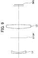
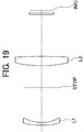
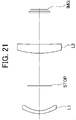
- It is an optical sectional view of an optical system for infrared rays of a 2nd embodiment of the present invention.
- It is an aberration diagram of the optical system for infrared rays of 2nd Embodiment of this invention, (a) is a spherical aberration difference figure, (b) is an astigmatism figure, (c) is a distortion aberration figure.
- 8 10, and 14 indicate spherical aberrations having wavelengths of 8 ⁇ m, 10 ⁇ m, and 14 ⁇ m, respectively.
- S indicates astigmatism in the sagittal direction at a wavelength of 10 ⁇ m
- M indicates astigmatism in the meridional direction at a wavelength of 10 ⁇ m. It is an optical sectional view of an optical system for infrared rays of a 3rd embodiment of the present invention.
- FIG. 1 It is an aberration diagram of the optical system for infrared rays of 3rd Embodiment of this invention, (a) is a spherical aberration difference figure, (b) is an astigmatism figure, (c) is a distortion aberration figure.
- spherical aberration diagram (a) 8 10, and 14 indicate spherical aberrations having wavelengths of 8 ⁇ m, 10 ⁇ m, and 14 ⁇ m, respectively.
- S indicates astigmatism in the sagittal direction at a wavelength of 10 ⁇ m
- M indicates astigmatism in the meridional direction at a wavelength of 10 ⁇ m.
- It is an aberration diagram of the optical system for infrared rays of 4th Embodiment of this invention (a) is a spherical aberration diagram, (b) is an astigmatism diagram, (c) is a distortion aberration diagram.
- 8, 10, and 14 indicate spherical aberrations having wavelengths of 8 ⁇ m, 10 ⁇ m, and 14 ⁇ m, respectively.
- S indicates astigmatism in the sagittal direction at a wavelength of 10 ⁇ m
- M indicates astigmatism in the meridional direction at a wavelength of 10 ⁇ m.
- It is an optical sectional view of the optical system for infrared rays of a 5th embodiment of the present invention.
- It is an aberration diagram of the optical system for infrared rays of 5th Embodiment of this invention, (a) is a spherical aberration diagram, (b) is an astigmatism diagram, (c) is a distortion aberration diagram.
- 8 10, and 14 indicate spherical aberrations having wavelengths of 8 ⁇ m, 10 ⁇ m, and 14 ⁇ m, respectively.
- S indicates astigmatism in the sagittal direction at a wavelength of 10 ⁇ m
- M indicates astigmatism in the meridional direction at a wavelength of 10 ⁇ m.
- FIG. 1 It is an aberration diagram of the optical system for infrared rays of 6th Embodiment of this invention, (a) is a spherical aberration diagram, (b) is an astigmatism diagram, (c) is a distortion aberration diagram.
- spherical aberration diagram (a) 8 10, and 14 indicate spherical aberrations having wavelengths of 8 ⁇ m, 10 ⁇ m, and 14 ⁇ m, respectively.
- S indicates astigmatism in the sagittal direction at a wavelength of 10 ⁇ m
- M indicates astigmatism in the meridional direction at a wavelength of 10 ⁇ m.
- FIG. 1 It is an aberration diagram of the optical system for infrared rays of 8th Embodiment of this invention, (a) is a spherical aberration difference figure, (b) is an astigmatism figure, (c) is a distortion aberration figure.
- spherical aberration diagram (a) 8, 10, and 14 indicate spherical aberrations having wavelengths of 8 ⁇ m, 10 ⁇ m, and 14 ⁇ m, respectively.
- S indicates astigmatism in the sagittal direction at a wavelength of 10 ⁇ m
- M indicates astigmatism in the meridional direction at a wavelength of 10 ⁇ m.
- It is an aberration diagram of the optical system for infrared rays of 9th Embodiment of this invention (a) is a spherical aberration difference figure, (b) is an astigmatism figure, (c) is a distortion aberration figure.
- 8, 10, and 14 indicate spherical aberrations having wavelengths of 8 ⁇ m, 10 ⁇ m, and 14 ⁇ m, respectively.
- S indicates astigmatism in the sagittal direction at a wavelength of 10 ⁇ m
- M indicates astigmatism in the meridional direction at a wavelength of 10 ⁇ m.
- It is an optical sectional view of an optical system for infrared rays of a 10th embodiment of the present invention.
- It is an aberration diagram of the optical system for infrared rays of 10th Embodiment of this invention, (a) is a spherical aberration diagram, (b) is an astigmatism diagram, (c) is a distortion aberration diagram.
- 8 10, and 14 indicate spherical aberrations having wavelengths of 8 ⁇ m, 10 ⁇ m, and 14 ⁇ m, respectively.
- S indicates astigmatism in the sagittal direction at a wavelength of 10 ⁇ m
- M indicates astigmatism in the meridional direction at a wavelength of 10 ⁇ m.
- FIG. 1 It is an aberration diagram of the optical system for infrared rays of 9th Embodiment of this invention, (a) is a spherical aberration difference figure, (b) is an astigmatism figure, (c) is a distortion aberration figure.
- spherical aberration diagram (a) 8 10, and 14 indicate spherical aberrations having wavelengths of 8 ⁇ m, 10 ⁇ m, and 14 ⁇ m, respectively.
- S indicates astigmatism in the sagittal direction at a wavelength of 10 ⁇ m
- M indicates astigmatism in the meridional direction at a wavelength of 10 ⁇ m.
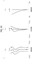
- It is an aberration diagram of the optical system for infrared rays of 10th Embodiment of this invention (a) is a spherical aberration diagram, (b) is an astigmatism diagram, (c) is a distortion aberration diagram.
- spherical aberration diagram (a) 8, 10, and 14 indicate spherical aberrations having wavelengths of 8 ⁇ m, 10 ⁇ m, and 14 ⁇ m, respectively.
- S indicates astigmatism in the sagittal direction at a wavelength of 10 ⁇ m
- M indicates astigmatism in the meridional direction at a wavelength of 10 ⁇ m.
- the wavelength is 10 ⁇ m.
- Focal length: f 10.3mm
Landscapes
- Physics & Mathematics (AREA)
- General Physics & Mathematics (AREA)
- Optics & Photonics (AREA)
- Health & Medical Sciences (AREA)
- Toxicology (AREA)
- Lenses (AREA)
Priority Applications (1)
| Application Number | Priority Date | Filing Date | Title |
|---|---|---|---|
| US14/386,501 US20150070754A1 (en) | 2012-03-21 | 2013-03-21 | Infrared optical system |
Applications Claiming Priority (2)
| Application Number | Priority Date | Filing Date | Title |
|---|---|---|---|
| JP2012-063934 | 2012-03-21 | ||
| JP2012063934A JP5906859B2 (ja) | 2012-03-21 | 2012-03-21 | 赤外線用光学系 |
Publications (1)
| Publication Number | Publication Date |
|---|---|
| WO2013141284A1 true WO2013141284A1 (fr) | 2013-09-26 |
Family
ID=49222741
Family Applications (1)
| Application Number | Title | Priority Date | Filing Date |
|---|---|---|---|
| PCT/JP2013/058021 Ceased WO2013141284A1 (fr) | 2012-03-21 | 2013-03-21 | Système optique à rayons infrarouges |
Country Status (3)
| Country | Link |
|---|---|
| US (1) | US20150070754A1 (fr) |
| JP (1) | JP5906859B2 (fr) |
| WO (1) | WO2013141284A1 (fr) |
Cited By (2)
| Publication number | Priority date | Publication date | Assignee | Title |
|---|---|---|---|---|
| CN110596867A (zh) * | 2019-10-18 | 2019-12-20 | 沈阳师范大学 | 手机超广角镜头用适配镜头 |
| CN113484999A (zh) * | 2021-07-02 | 2021-10-08 | 沈阳师范大学 | 调焦用变焦镜头 |
Families Citing this family (9)
| Publication number | Priority date | Publication date | Assignee | Title |
|---|---|---|---|---|
| DE112014006674B4 (de) * | 2014-08-07 | 2018-10-31 | Han's Laser Technology Industry Group Co., Ltd. | Linsensatz zur Bilderfassung von langwelligem Infrarot, Objektiv und Brandherddetektor |
| JPWO2016027786A1 (ja) * | 2014-08-20 | 2017-06-01 | コニカミノルタ株式会社 | 遠赤外線レンズ,撮像光学装置及びデジタル機器 |
| JP6583407B2 (ja) * | 2015-05-27 | 2019-10-02 | コニカミノルタ株式会社 | 赤外線用光学系,撮像光学装置及びデジタル機器 |
| JP6848967B2 (ja) * | 2016-05-13 | 2021-03-24 | コニカミノルタ株式会社 | 赤外線用光学系,撮像光学装置及びデジタル機器 |
| JPWO2017195731A1 (ja) * | 2016-05-13 | 2019-03-14 | コニカミノルタ株式会社 | 赤外線用光学系,撮像光学装置及びデジタル機器 |
| TWI627462B (zh) * | 2017-06-06 | 2018-06-21 | 新鉅科技股份有限公司 | 二片式紅外單波長投影鏡片組 |
| CN109116510B (zh) * | 2017-06-23 | 2020-11-17 | 新巨科技股份有限公司 | 二片式红外单波长投影镜片组 |
| JP7738224B2 (ja) * | 2021-03-04 | 2025-09-12 | パナソニックIpマネジメント株式会社 | 赤外線検出装置 |
| CN115220197B (zh) * | 2022-08-26 | 2024-09-03 | 中山依瓦塔光学有限公司 | 一种中红外波段的中继镜 |
Citations (6)
| Publication number | Priority date | Publication date | Assignee | Title |
|---|---|---|---|---|
| JP2000089105A (ja) * | 1998-09-11 | 2000-03-31 | Olympus Optical Co Ltd | 対物光学系 |
| JP2001141998A (ja) * | 1999-11-12 | 2001-05-25 | Olympus Optical Co Ltd | ズームレンズ |
| US20090052018A1 (en) * | 2007-08-23 | 2009-02-26 | Recon/Optical, Inc. | Compact two-element infrared objective lens and IR or thermal sight for weapon having viewing optics |
| JP2011199714A (ja) * | 2010-03-23 | 2011-10-06 | Kyocera Corp | 撮像装置 |
| JP2011237669A (ja) * | 2010-05-12 | 2011-11-24 | Fujifilm Corp | 赤外線用結像レンズおよび撮像装置 |
| JP2012505425A (ja) * | 2008-10-07 | 2012-03-01 | オヌラ(オフィス ナシオナル デトゥードゥ エ ドゥ ルシェルシェ アエロスパシアル) | 真空筐体内に統合された赤外線広視野撮像システム |
Family Cites Families (2)
| Publication number | Priority date | Publication date | Assignee | Title |
|---|---|---|---|---|
| CN101833164A (zh) * | 2009-03-10 | 2010-09-15 | 鸿富锦精密工业(深圳)有限公司 | 红外取像镜头 |
| TWI432821B (zh) * | 2011-01-20 | 2014-04-01 | Largan Precision Co | 攝影用光學透鏡組 |
-
2012
- 2012-03-21 JP JP2012063934A patent/JP5906859B2/ja active Active
-
2013
- 2013-03-21 US US14/386,501 patent/US20150070754A1/en not_active Abandoned
- 2013-03-21 WO PCT/JP2013/058021 patent/WO2013141284A1/fr not_active Ceased
Patent Citations (6)
| Publication number | Priority date | Publication date | Assignee | Title |
|---|---|---|---|---|
| JP2000089105A (ja) * | 1998-09-11 | 2000-03-31 | Olympus Optical Co Ltd | 対物光学系 |
| JP2001141998A (ja) * | 1999-11-12 | 2001-05-25 | Olympus Optical Co Ltd | ズームレンズ |
| US20090052018A1 (en) * | 2007-08-23 | 2009-02-26 | Recon/Optical, Inc. | Compact two-element infrared objective lens and IR or thermal sight for weapon having viewing optics |
| JP2012505425A (ja) * | 2008-10-07 | 2012-03-01 | オヌラ(オフィス ナシオナル デトゥードゥ エ ドゥ ルシェルシェ アエロスパシアル) | 真空筐体内に統合された赤外線広視野撮像システム |
| JP2011199714A (ja) * | 2010-03-23 | 2011-10-06 | Kyocera Corp | 撮像装置 |
| JP2011237669A (ja) * | 2010-05-12 | 2011-11-24 | Fujifilm Corp | 赤外線用結像レンズおよび撮像装置 |
Cited By (4)
| Publication number | Priority date | Publication date | Assignee | Title |
|---|---|---|---|---|
| CN110596867A (zh) * | 2019-10-18 | 2019-12-20 | 沈阳师范大学 | 手机超广角镜头用适配镜头 |
| CN110596867B (zh) * | 2019-10-18 | 2021-07-30 | 沈阳师范大学 | 手机超广角镜头用适配镜头 |
| CN113484999A (zh) * | 2021-07-02 | 2021-10-08 | 沈阳师范大学 | 调焦用变焦镜头 |
| CN113484999B (zh) * | 2021-07-02 | 2022-04-29 | 沈阳师范大学 | 调焦用变焦镜头 |
Also Published As
| Publication number | Publication date |
|---|---|
| JP5906859B2 (ja) | 2016-04-20 |
| US20150070754A1 (en) | 2015-03-12 |
| JP2013195795A (ja) | 2013-09-30 |
Similar Documents
| Publication | Publication Date | Title |
|---|---|---|
| JP5906859B2 (ja) | 赤外線用光学系 | |
| JP5736924B2 (ja) | 撮像レンズおよび撮像装置 | |
| US9690080B2 (en) | Wide angle lens | |
| JP5252842B2 (ja) | 撮像レンズ | |
| JP5993604B2 (ja) | 赤外線用光学系 | |
| JP7396788B2 (ja) | 撮像レンズ | |
| CN111929809A (zh) | 摄像镜头 | |
| JP4796660B2 (ja) | 2枚組撮像光学系およびそれを備えた撮像装置 | |
| JP6254804B2 (ja) | 赤外線光学系 | |
| CN110850550A (zh) | 摄像镜头 | |
| US9182574B2 (en) | Infrared fixed-focus lens | |
| US7990615B2 (en) | Diffractive optical system and eyepiece optical system | |
| CN113534411A (zh) | 摄像镜头 | |
| JP6490115B2 (ja) | 撮像レンズ | |
| JP2019066645A (ja) | 広角レンズ | |
| JP7360266B2 (ja) | 撮像レンズ | |
| US20120212807A1 (en) | Infrared Lens | |
| WO2018066641A1 (fr) | Lentille d'imagerie et dispositif d'imagerie | |
| JP2013092774A (ja) | レンズシステム | |
| JP4776988B2 (ja) | 光学系及びそれを有する光学機器 | |
| JP2013114262A (ja) | ズームレンズ | |
| JP2012173561A (ja) | 赤外線レンズ | |
| JP2019008271A (ja) | 光学系及びそれを有する撮像装置 | |
| WO2020262488A1 (fr) | Lentille à grand angle | |
| CN117242386A (zh) | 红外线成像镜头 |
Legal Events
| Date | Code | Title | Description |
|---|---|---|---|
| 121 | Ep: the epo has been informed by wipo that ep was designated in this application |
Ref document number: 13764411 Country of ref document: EP Kind code of ref document: A1 |
|
| WWE | Wipo information: entry into national phase |
Ref document number: 14386501 Country of ref document: US |
|
| NENP | Non-entry into the national phase |
Ref country code: DE |
|
| 122 | Ep: pct application non-entry in european phase |
Ref document number: 13764411 Country of ref document: EP Kind code of ref document: A1 |