WO2013141284A1 - 赤外線用光学系 - Google Patents
赤外線用光学系 Download PDFInfo
- Publication number
- WO2013141284A1 WO2013141284A1 PCT/JP2013/058021 JP2013058021W WO2013141284A1 WO 2013141284 A1 WO2013141284 A1 WO 2013141284A1 JP 2013058021 W JP2013058021 W JP 2013058021W WO 2013141284 A1 WO2013141284 A1 WO 2013141284A1
- Authority
- WO
- WIPO (PCT)
- Prior art keywords
- lens
- optical system
- conditional expression
- infrared
- astigmatism
- Prior art date
- Legal status (The legal status is an assumption and is not a legal conclusion. Google has not performed a legal analysis and makes no representation as to the accuracy of the status listed.)
- Ceased
Links
Images






Classifications
-
- G—PHYSICS
- G02—OPTICS
- G02B—OPTICAL ELEMENTS, SYSTEMS OR APPARATUS
- G02B9/00—Optical objectives characterised both by the number of the components and their arrangements according to their sign, i.e. + or -
- G02B9/04—Optical objectives characterised both by the number of the components and their arrangements according to their sign, i.e. + or - having two components only
- G02B9/10—Optical objectives characterised both by the number of the components and their arrangements according to their sign, i.e. + or - having two components only one + and one - component
-
- G—PHYSICS
- G02—OPTICS
- G02B—OPTICAL ELEMENTS, SYSTEMS OR APPARATUS
- G02B13/00—Optical objectives specially designed for the purposes specified below
- G02B13/14—Optical objectives specially designed for the purposes specified below for use with infrared or ultraviolet radiation
Definitions
- the present invention relates to an infrared optical system, and more particularly to a wide-angle infrared optical system used in an infrared imaging device or the like.
- the infrared rays are radiation including mid-infrared rays having a wavelength of 3 ⁇ m to 5 ⁇ m and far infrared rays having a wavelength of 8 ⁇ m to 14 ⁇ m.
- infrared optical systems are strongly desired to be composed of a small number of lenses because the infrared lens materials such as germanium (Ge) and chalcogenite are very expensive.
- a conventional two-lens configuration infrared optical system is composed of two lenses, a first lens L1 and a second lens L2, both made of zinc sulfide (ZnS) in order from the object side. Things have been proposed.
- the first lens L1 has a positive meniscus shape with a convex surface facing the object side, and the concave side has an aspheric shape having a diffractive action, and the second lens L2 has at least one surface aspherical (for example, Patent Document 1).
- Another conventional two-lens infrared optical system is a convex meniscus that is used in the wavelength range from 3 ⁇ m to 14 ⁇ m from infrared to far infrared, with the convex surface facing the object side in order from the object side. And a convex meniscus second lens with a concave surface facing the object side, and at least one of the first lens and the second lens is a diffractive optical element surface.
- An infrared optical system is proposed (see, for example, Patent Document 2).
- Another conventional two-lens infrared optical system is composed of a first lens G1 and a second lens G1 in order from the object side, and the first lens G1 has a convex surface facing the object side.
- Positive meniscus shape the second lens G2 has a positive meniscus shape with a convex surface facing the image side
- the image side surface of the first lens G1 or the object side surface of the second lens G2 is a diffractive optical surface, and other than the diffractive optical surface
- Infrared optical systems in which one or more surfaces are aspherical have been proposed (see, for example, Patent Document 3).
- an infrared optical system used in a dark field monitoring device or the like is desired to have a wide stationary monitoring region, and an infrared optical system with a wide angle of view has been proposed.
- an infrared optical system that includes a first lens group G1 having a negative refractive power including a negative meniscus lens L11 facing the lens and a second lens group G2 having a positive refractive power and satisfying a predetermined conditional expression.
- the infrared optical system disclosed in Patent Document 1 has a two-sheet configuration and an angle of view of 18 °. Since the lens configuration is a positive lens and a positive or negative lens with weak power in order from the object side, the Petzval sum is large, and it is difficult to keep the image plane flat when the angle is widened. Further, in the configuration of Patent Document 1, when the angle of view exceeds 20 °, it is difficult to correct off-axis aberrations with the two-lens configuration, and thus the three-lens configuration is used. (2) The infrared lens disclosed in the cited document 2 is an infrared optical system having a two-lens configuration and an angle of view of 28 °.
- the lens configuration is a positive lens and a positive lens in order from the object side
- the Petzval sum is large, and it is difficult to keep the image plane flat when the angle is widened.
- the infrared imaging lens disclosed in the cited document 3 is an infrared optical system having a two-lens configuration and an angle of view of 34 °, it has a configuration of a positive lens and a positive lens in order from the object side.
- the Petzval sum is large, and when the angle is widened, it is difficult to keep the image plane flat.
- the infrared optical system disclosed in the cited document 4 is a negative lens preceding type and has an angle of view of 66 °. However, four or five constituent lenses are required, and there is a problem that the amount of light loss due to lens transmission and lens surface reflection is large in addition to high manufacturing costs.
- the present invention has been made in view of the above-described problems of the prior art relating to an infrared optical system, and has two lens configurations and has an aberration optically corrected well even at a wide angle of view.
- the purpose is to provide a system.
- an object of the present invention is to provide an infrared optical system capable of ensuring an image plane without increasing the Petzval sum even if a wide angle of view of 40 ° to 110 ° is obtained.
- the first lens having negative refractive power and the second lens having positive refractive power are composed of two lenses,
- the first lens is a shape with a concave surface facing the image side
- the second lens has a shape with a convex surface facing the object side
- An infrared optical system that satisfies the following conditional expression (1): 2.1 ⁇ d / f ⁇ 11 (1)
- d Distance on the optical axis from the image side surface of the first lens to the object side surface of the second lens
- f The focal length of the entire system.
- conditional expression (1) preferably, 2.9 ⁇ d / f ⁇ 5.5 (1 ') It is.
- the infrared optical system of the present invention it is possible to configure an infrared optical system in which aberrations are favorably corrected even at a wide angle of view while having two lenses.
- the Petzval sum does not increase, and an infrared optical system that secures an image plane can be configured.
- the Petzval sum of the infrared optical system of the present invention can be set to 1/3 or less of the infrared optical system of the cited document 2.
- conditional expression (1) If the lower limit of conditional expression (1) is not reached, the Petzval sum increases, making it difficult to keep the image plane flat and making it difficult to widen the angle. If the upper limit of conditional expression (1) is exceeded, it will be difficult to suppress lateral chromatic aberration. Moreover, the amount of astigmatism generated on each surface increases, the sensitivity of optical performance to manufacturing errors is high, and manufacturing becomes difficult.
- an infrared optical system in which aberrations are corrected more favorably even at a wide angle of view.
- an infrared optical system can be configured in which the Petzval sum is further reduced and a better image plane is ensured.
- Embodiments and effects of the present invention are as follows.
- (Embodiment 1) The infrared optical system according to the present invention is characterized in that a diaphragm is further disposed between the first lens and the second lens.
- the stop between the first lens having a negative refractive power and the second lens having a positive refractive power By disposing the stop between the first lens having a negative refractive power and the second lens having a positive refractive power, the off-axis light beam passes through a low place in both lenses, and the off-axis of each lens surface is off-axis. Since the amount of astigmatism of light rays can be suppressed, astigmatism can be corrected even with a small number of lenses. Further, by arranging the first lens having a negative refractive power on the object side from the stop, the entrance pupil is formed at a position closer to the object side than the stop, and the diameter of the entrance pupil is further reduced, so that the infrared optical system It is possible to greatly suppress the shortage of peripheral light amount, which is an important issue. On the other hand, disposing the diaphragm between the first lens and the second lens makes it easy to reduce the diameters of the first lens and the second lens.
- conditional expression (2) preferably, -1.6 ⁇ f1 / f2 ⁇ -0.96 (2 ') It is.
- the Petzval sum can be kept small, and the flatness of the image plane can be maintained and a wider angle can be obtained. Further, the amount of spherical aberration and coma generated on each lens surface is reduced, and correction of aberrations is facilitated.
- the infrared optical system of the present invention is characterized in that the first lens and the second lens are made of germanium.
- germanium which is a glass material with a high refractive index and excellent color dispersion characteristics for all lenses, it is easier to suppress spherical aberration and chromatic aberration than when using other glass materials such as chalcogenite. An effect can be obtained.
- conditional expression (3) If the lower limit or the upper limit of conditional expression (3) is exceeded, the amount of spherical aberration, coma, and astigmatism generated on each lens surface will increase, and the spherical aberration, coma, and astigmatism of the entire infrared optical system will increase. Correction of the collection part becomes difficult.
- conditional expression (3) preferably, 3.1 ⁇ r2 / f ⁇ 7.1 (3 ') It is.
- It is an aberration diagram of the optical system for infrared rays of 1st Embodiment of this invention (a) is a spherical aberration diagram, (b) is an astigmatism diagram, (c) is a distortion aberration diagram.
- 8, 10, and 14 indicate spherical aberrations having wavelengths of 8 ⁇ m, 10 ⁇ m, and 14 ⁇ m, respectively.
- S indicates astigmatism in the sagittal direction at a wavelength of 10 ⁇ m
- M indicates astigmatism in the meridional direction at a wavelength of 10 ⁇ m.
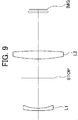
- It is an optical sectional view of an optical system for infrared rays of a 2nd embodiment of the present invention.
- It is an aberration diagram of the optical system for infrared rays of 2nd Embodiment of this invention, (a) is a spherical aberration difference figure, (b) is an astigmatism figure, (c) is a distortion aberration figure.
- 8 10, and 14 indicate spherical aberrations having wavelengths of 8 ⁇ m, 10 ⁇ m, and 14 ⁇ m, respectively.
- S indicates astigmatism in the sagittal direction at a wavelength of 10 ⁇ m
- M indicates astigmatism in the meridional direction at a wavelength of 10 ⁇ m. It is an optical sectional view of an optical system for infrared rays of a 3rd embodiment of the present invention.
- FIG. 1 It is an aberration diagram of the optical system for infrared rays of 3rd Embodiment of this invention, (a) is a spherical aberration difference figure, (b) is an astigmatism figure, (c) is a distortion aberration figure.
- spherical aberration diagram (a) 8 10, and 14 indicate spherical aberrations having wavelengths of 8 ⁇ m, 10 ⁇ m, and 14 ⁇ m, respectively.
- S indicates astigmatism in the sagittal direction at a wavelength of 10 ⁇ m
- M indicates astigmatism in the meridional direction at a wavelength of 10 ⁇ m.
- It is an aberration diagram of the optical system for infrared rays of 4th Embodiment of this invention (a) is a spherical aberration diagram, (b) is an astigmatism diagram, (c) is a distortion aberration diagram.
- 8, 10, and 14 indicate spherical aberrations having wavelengths of 8 ⁇ m, 10 ⁇ m, and 14 ⁇ m, respectively.
- S indicates astigmatism in the sagittal direction at a wavelength of 10 ⁇ m
- M indicates astigmatism in the meridional direction at a wavelength of 10 ⁇ m.
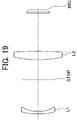
- It is an optical sectional view of the optical system for infrared rays of a 5th embodiment of the present invention.
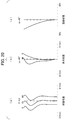
- It is an aberration diagram of the optical system for infrared rays of 5th Embodiment of this invention, (a) is a spherical aberration diagram, (b) is an astigmatism diagram, (c) is a distortion aberration diagram.
- 8 10, and 14 indicate spherical aberrations having wavelengths of 8 ⁇ m, 10 ⁇ m, and 14 ⁇ m, respectively.
- S indicates astigmatism in the sagittal direction at a wavelength of 10 ⁇ m
- M indicates astigmatism in the meridional direction at a wavelength of 10 ⁇ m.
- FIG. 1 It is an aberration diagram of the optical system for infrared rays of 6th Embodiment of this invention, (a) is a spherical aberration diagram, (b) is an astigmatism diagram, (c) is a distortion aberration diagram.
- spherical aberration diagram (a) 8 10, and 14 indicate spherical aberrations having wavelengths of 8 ⁇ m, 10 ⁇ m, and 14 ⁇ m, respectively.
- S indicates astigmatism in the sagittal direction at a wavelength of 10 ⁇ m
- M indicates astigmatism in the meridional direction at a wavelength of 10 ⁇ m.
- FIG. 1 It is an aberration diagram of the optical system for infrared rays of 8th Embodiment of this invention, (a) is a spherical aberration difference figure, (b) is an astigmatism figure, (c) is a distortion aberration figure.
- spherical aberration diagram (a) 8, 10, and 14 indicate spherical aberrations having wavelengths of 8 ⁇ m, 10 ⁇ m, and 14 ⁇ m, respectively.
- S indicates astigmatism in the sagittal direction at a wavelength of 10 ⁇ m
- M indicates astigmatism in the meridional direction at a wavelength of 10 ⁇ m.
- It is an aberration diagram of the optical system for infrared rays of 9th Embodiment of this invention (a) is a spherical aberration difference figure, (b) is an astigmatism figure, (c) is a distortion aberration figure.
- 8, 10, and 14 indicate spherical aberrations having wavelengths of 8 ⁇ m, 10 ⁇ m, and 14 ⁇ m, respectively.
- S indicates astigmatism in the sagittal direction at a wavelength of 10 ⁇ m
- M indicates astigmatism in the meridional direction at a wavelength of 10 ⁇ m.
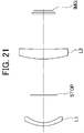
- It is an optical sectional view of an optical system for infrared rays of a 10th embodiment of the present invention.
- It is an aberration diagram of the optical system for infrared rays of 10th Embodiment of this invention, (a) is a spherical aberration diagram, (b) is an astigmatism diagram, (c) is a distortion aberration diagram.
- 8 10, and 14 indicate spherical aberrations having wavelengths of 8 ⁇ m, 10 ⁇ m, and 14 ⁇ m, respectively.
- S indicates astigmatism in the sagittal direction at a wavelength of 10 ⁇ m
- M indicates astigmatism in the meridional direction at a wavelength of 10 ⁇ m.
- FIG. 1 It is an aberration diagram of the optical system for infrared rays of 9th Embodiment of this invention, (a) is a spherical aberration difference figure, (b) is an astigmatism figure, (c) is a distortion aberration figure.
- spherical aberration diagram (a) 8 10, and 14 indicate spherical aberrations having wavelengths of 8 ⁇ m, 10 ⁇ m, and 14 ⁇ m, respectively.
- S indicates astigmatism in the sagittal direction at a wavelength of 10 ⁇ m
- M indicates astigmatism in the meridional direction at a wavelength of 10 ⁇ m.
- It is an aberration diagram of the optical system for infrared rays of 10th Embodiment of this invention (a) is a spherical aberration diagram, (b) is an astigmatism diagram, (c) is a distortion aberration diagram.
- spherical aberration diagram (a) 8, 10, and 14 indicate spherical aberrations having wavelengths of 8 ⁇ m, 10 ⁇ m, and 14 ⁇ m, respectively.
- S indicates astigmatism in the sagittal direction at a wavelength of 10 ⁇ m
- M indicates astigmatism in the meridional direction at a wavelength of 10 ⁇ m.
- the wavelength is 10 ⁇ m.
- Focal length: f 10.3mm
Landscapes
- Physics & Mathematics (AREA)
- General Physics & Mathematics (AREA)
- Optics & Photonics (AREA)
- Health & Medical Sciences (AREA)
- Toxicology (AREA)
- Lenses (AREA)
Description
本発明は、赤外線用光学系、さらに詳しくは、赤外線撮像装置等に用いる広角の赤外線用光学系に関する。ここで、赤外線とは、波長が3μm~5μmの中赤外線、及び波長が8μm~14μmの遠赤外線を含む放射である。
背景技術
背景技術
従来の赤外線用光学系は、使用されるゲルマニウム(Ge)、カルコゲナイト等の赤外線用レンズ材料が非常に高価であるため、少ないレンズ枚数で構成されることが強く望まれている。
(1)従来の2枚レンズ構成の赤外線用光学系としては、物体側から順に、共に硫化亜鉛(ZnS)を材料とする第1レンズL1および第2レンズL2の2枚のレンズで構成されたものが提案されている。第1レンズL1は、物体側に凸面を向けた正メニスカス形状で、かつ凹面側が回折作用を有する非球面形状、第2レンズL2は、少なくとも一方の面が非球面形状とされている(例えば、特許文献1参照)。
(2)従来の他の2枚レンズ構成の赤外線用光学系としては、3μmから14μmまでの赤外線から遠赤外線までの波長域で用いられ、物体側より順に、物体側に凸面を向けた凸メニスカスの第1レンズと、物体側に凹面を向けた凸メニスカスの第2レンズの2枚のレンズで構成され、第1レンズと第2レンズの少なくとも一方の両面を回折光学素子面としたことを特徴とする赤外線光学系が提案されている(例えば、特許文献2参照)。
(3)従来の他の2枚レンズ構成の赤外線用光学系としては、物体側より順に、第1レンズG1と第2レンズG1とで構成し、第1レンズG1は物体側に凸面を向けた正メニスカス形状、第2レンズG2は像側に凸面を向けた正メニスカス形状とし、第1レンズG1の像側の面または第2レンズG2の物体側の面を回折光学面とし、回折光学面以外の1以上の面を非球面とする赤外線用光学系が提案されている(例えば、特許文献3参照)。
(4)一方、暗視野監視装置等に使用する赤外線用光学系は、広い静止監視領域をもつことが望まれ、画角の広い赤外線用光学系が提案されている。例えば、レンズの構成枚数が少なく、バックフォーカスが大きく、歪曲を含めた諸収差を良好に補正した明るい赤外光学系等を目指したもので、物体側から順に、少なくとも1枚の物体側に凸面を向けた負メニスカスレンズL11を含む負の屈折力を有する第一レンズ群G1と、正の屈折力を有する第二レンズ群G2とから構成され、所定の条件式を満足する赤外線用光学系である(特許文献4参照)。
(1)特許文献1に開示された赤外線光学系は、2枚構成で画角が18°である。レンズ構成は、物体側から順に、正レンズ、パワーの弱い正または負レンズという構成であるため、ペッツバール和が大きく、広角化すると像面をフラットに保つことが困難である。また、特許文献1の構成においては、画角が20°を超える場合、レンズ2枚構成では軸外収差の補正が困難であるから、レンズ3枚構成となっている。
(2)引用文献2に開示された赤外線レンズは、2枚構成で画角が28°の赤外線用光学系である。しかしそのレンズ構成が、物体側から順に、正レンズ、正レンズという構成であるため、ペッツバール和が大きく、広角化すると像面をフラットに保つことが困難である。
(3)引用文献3に開示された赤外線用結像レンズは、2枚構成で画角が34°の赤外線用光学系であるが、物体側から順に、正レンズ、正レンズという構成であるため、ペッツバール和が大きく、広角化すると像面をフラットに保つことが困難である。
(4)引用文献4に開示された赤外光学系は、負レンズ先行タイプで画角が66°である。しかし、構成レンズは、4枚又は5枚が必要であり、高い製造コストに加えレンズ透過やレンズ表面反射による光量損失が大きいという問題がある。
(2)引用文献2に開示された赤外線レンズは、2枚構成で画角が28°の赤外線用光学系である。しかしそのレンズ構成が、物体側から順に、正レンズ、正レンズという構成であるため、ペッツバール和が大きく、広角化すると像面をフラットに保つことが困難である。
(3)引用文献3に開示された赤外線用結像レンズは、2枚構成で画角が34°の赤外線用光学系であるが、物体側から順に、正レンズ、正レンズという構成であるため、ペッツバール和が大きく、広角化すると像面をフラットに保つことが困難である。
(4)引用文献4に開示された赤外光学系は、負レンズ先行タイプで画角が66°である。しかし、構成レンズは、4枚又は5枚が必要であり、高い製造コストに加えレンズ透過やレンズ表面反射による光量損失が大きいという問題がある。
(発明の目的)
本発明は、赤外線用光学系に関する先行技術の上述した問題点に鑑みてなされたものであって、レンズ構成が2枚でありながら、広画角においても収差が良好に補正された赤外線用光学系を提供することを目的とする。特に、40°から110°の広画角を得ても、ペッツバール和が大きくならず、像平面を確保できる赤外線用光学系を提供することを目的とする。
本発明は、赤外線用光学系に関する先行技術の上述した問題点に鑑みてなされたものであって、レンズ構成が2枚でありながら、広画角においても収差が良好に補正された赤外線用光学系を提供することを目的とする。特に、40°から110°の広画角を得ても、ペッツバール和が大きくならず、像平面を確保できる赤外線用光学系を提供することを目的とする。
本発明は、
物体側から順に、負の屈折力を有する第1レンズと、正の屈折力を有する第2レンズの2枚のレンズから構成され、
第1レンズは、像側に凹面を向けた形状であり、
第2レンズは、物体側に凸面を向けた形状であり、
以下の条件式(1)を満たすことを特徴とする赤外線用光学系。
2.1 ≦ d/f ≦ 11 ・・・・・(1)
ただし、
d:第1レンズの像側の面から第2レンズの物体側の面までの光軸上の距離
f:全系の焦点距離
である。
なお、条件式(1)に関し、好ましくは、
2.9≦ d/f ≦ 5.5 ・・・・(1’)
である。
物体側から順に、負の屈折力を有する第1レンズと、正の屈折力を有する第2レンズの2枚のレンズから構成され、
第1レンズは、像側に凹面を向けた形状であり、
第2レンズは、物体側に凸面を向けた形状であり、
以下の条件式(1)を満たすことを特徴とする赤外線用光学系。
2.1 ≦ d/f ≦ 11 ・・・・・(1)
ただし、
d:第1レンズの像側の面から第2レンズの物体側の面までの光軸上の距離
f:全系の焦点距離
である。
なお、条件式(1)に関し、好ましくは、
2.9≦ d/f ≦ 5.5 ・・・・(1’)
である。
本発明の赤外線用光学系によれば、レンズ構成が2枚でありながら、広画角においても収差が良好に補正された赤外線用光学系を構成することができる。特に、40°から110°の広画角を得ても、ペッツバール和が大きくならず、像平面を確保した赤外線用光学系を構成できる。例えば、本発明の赤外線用光学系のペッツバール和は、引用文献2の赤外線用光学系の1/3以下にすることができる。
条件式(1)の下限を下回ると、ペッツバール和が大きくなり、像面を平面に保つのが難しく、広角化が困難になる。条件式(1)の上限を上回ると、倍率色収差の抑制が困難となる。また、各面における非点収差の発生量が大きくなり、製造誤差に対する光学性能の感度が高く、製造が難しくなる。
条件式(1’)を満たすことにより、広画角においても収差がより良好に補正された赤外線用光学系を構成することができる。特に、40°から110°の広画角を得ても、ペッツバール和をより小さく抑え、より良い像平面を確保した赤外線用光学系を構成できる。
本発明の実施態様及びその効果は以下の通りである。
(実施態様1)
上記本発明の赤外線用光学系において、更に、絞りが、前記第1レンズと第2レンズとの間に配置されていことを特徴とする。
(実施態様1)
上記本発明の赤外線用光学系において、更に、絞りが、前記第1レンズと第2レンズとの間に配置されていことを特徴とする。
絞りを負の屈折力の第1レンズと正の屈折力の第2レンズとの間に配置することにより、両レンズにおいて軸外光線が低いところを通過するようになり、各レンズ面の軸外光線の非点収差等の発生量を抑えることができるので、少ないレンズ枚数であっても、非点収差を補正することができる。
また、負の屈折力の第1レンズを絞りより物体側に配置することにより、入射瞳を絞りより物体側の位置に形成し、さらに入射瞳の直径を小さくすることにより、赤外線用光学系で重要な課題である周辺光量の不足を大幅の抑えることができる。
一方、絞りを前記第1レンズと第2レンズとの間に配置することは、前記第1レンズと第2レンズの直径を小さくし易い。
また、負の屈折力の第1レンズを絞りより物体側に配置することにより、入射瞳を絞りより物体側の位置に形成し、さらに入射瞳の直径を小さくすることにより、赤外線用光学系で重要な課題である周辺光量の不足を大幅の抑えることができる。
一方、絞りを前記第1レンズと第2レンズとの間に配置することは、前記第1レンズと第2レンズの直径を小さくし易い。
(実施態様2)
上記本発明の赤外線用光学系において、更に、以下の条件式(2)を満たすことを特徴とする。
-2.1 ≦ f1/f2 ≦ -0.80 ・・・・(2)
ただし、
f1:第1レンズの焦点距離
f2:第2レンズの焦点距離
上記本発明の赤外線用光学系において、更に、以下の条件式(2)を満たすことを特徴とする。
-2.1 ≦ f1/f2 ≦ -0.80 ・・・・(2)
ただし、
f1:第1レンズの焦点距離
f2:第2レンズの焦点距離
条件式(2)の下限を下回ると、ペッツバール和が大きくなり、像面の平面性を保つことができず、広角化ができない。
条件式(2)の上限を上回ると、ペッツバール和が負の方向に大きくなる。条件式(2)の上限を上回ると、さらに各レンズ面での球面収差、コマ収差の発生量が大きくなり、収差の補正が困難になる。
条件式(2)の上限を上回ると、ペッツバール和が負の方向に大きくなる。条件式(2)の上限を上回ると、さらに各レンズ面での球面収差、コマ収差の発生量が大きくなり、収差の補正が困難になる。
条件式(2)に関し、好ましくは、
-1.6 ≦ f1/f2 ≦ -0.96 ・・・(2’)
である。
-1.6 ≦ f1/f2 ≦ -0.96 ・・・(2’)
である。
条件式(2’)を満たすことにより、ペッツバール和を小さく抑え、像面の平面性を保ってより広角化が可能となる。さらに、各レンズ面での球面収差、コマ収差の発生量が小さくり、収差の補正が容易になる。
(実施態様3)
上記本発明の赤外線用光学系において、更に、前記第1レンズと第2レンズがゲルマニウムからなることを特徴とする。
上記本発明の赤外線用光学系において、更に、前記第1レンズと第2レンズがゲルマニウムからなることを特徴とする。
全てのレンズを屈折率が高く、色分散特性に優れたガラス材料であるゲルマニウムを使用することにより、カルコゲナイト等他のガラス材料を使用する場合に比較して、球面収差や色収差を抑制し易いという効果を得ることができる。
(実施態様4)
上記本発明の赤外線用光学系において、更に、以下の条件式(3)を満たすことを特徴とする。
0.8 ≦ r2/f ≦ 60 ・・・(3)
ただし、
r2:第1レンズの像側の面の曲率半径
f :全系の焦点距離
上記本発明の赤外線用光学系において、更に、以下の条件式(3)を満たすことを特徴とする。
0.8 ≦ r2/f ≦ 60 ・・・(3)
ただし、
r2:第1レンズの像側の面の曲率半径
f :全系の焦点距離
条件式(3)の下限を下回る又は上限を上回ると、各レンズ面での球面収差、コマ収差、非点収差の発生量が大きくなり、赤外線用光学系全体の球面収差、コマ収差、非点集載物部の補正が困難になる。
条件式(3)に関し、好ましくは、
3.1 ≦ r2/f ≦ 7.1 ・・・(3’)
である。
3.1 ≦ r2/f ≦ 7.1 ・・・(3’)
である。
条件式(3’)を満たすことにより、各レンズ面での球面収差、コマ収差の発生量が小さくり、収差の補正が容易になる。
以下に、本発明の赤外線レンズの実施形態のレンズデータ等を示す。波長は、10μmである。
(第1実施形態)
焦点距離: f = 10.3mm
FNo. = 1.0
画角(2ω) = 70°
面番号 曲率半径 面間隔 光学材料 Nd
*1 337.1818 2.17 Ge 4.0044
*2 54.0041 20.41 1.0000
(絞り)3 INF 14.59 1.0000
*4 60.7849 4.27 Ge 4.0044
*5 -526.8440 24.71 1.0000
6 INF 1.00 Ge 4.0044
7 INF 1.00 1.0000
(第1実施形態)
焦点距離: f = 10.3mm
FNo. = 1.0
画角(2ω) = 70°
面番号 曲率半径 面間隔 光学材料 Nd
*1 337.1818 2.17 Ge 4.0044
*2 54.0041 20.41 1.0000
(絞り)3 INF 14.59 1.0000
*4 60.7849 4.27 Ge 4.0044
*5 -526.8440 24.71 1.0000
6 INF 1.00 Ge 4.0044
7 INF 1.00 1.0000
非球面係数

条件式に係る値
条件式(1) d/f = 3.41
条件式(2) f1/f2=-1.18
条件式(3) r2/f = 5.27
条件式(1) d/f = 3.41
条件式(2) f1/f2=-1.18
条件式(3) r2/f = 5.27
(第2実施形態)
焦点距離: f =11.5mm
FNo. = 1.0
画角(2ω) = 60°
焦点距離: f =11.5mm
FNo. = 1.0
画角(2ω) = 60°
面番号 曲率半径 面間隔 光学材料 Nd
*1 -2010.8899 2.34 Ge 4.0044
*2 75.3424 21.46 1.0000
(絞り)3 INF 14.38 1.0000
*4 70.4046 4.90 Ge 4.0044
*5 -323.1153 26.40 1.0000
6 INF 1.00 Ge 4.0044
7 INF 1.00 1.0000
*1 -2010.8899 2.34 Ge 4.0044
*2 75.3424 21.46 1.0000
(絞り)3 INF 14.38 1.0000
*4 70.4046 4.90 Ge 4.0044
*5 -323.1153 26.40 1.0000
6 INF 1.00 Ge 4.0044
7 INF 1.00 1.0000
非球面係数

条件式に係る値
条件式(1) d/f = 3.12
条件式(2) f1/f2=-1.24
条件式(3) r2/f = 6.55
条件式(1) d/f = 3.12
条件式(2) f1/f2=-1.24
条件式(3) r2/f = 6.55
(第3実施形態)
焦点距離: f = 7.6mm
FNo. = 1.0
画角(2ω) = 110°
焦点距離: f = 7.6mm
FNo. = 1.0
画角(2ω) = 110°
面番号 曲率半径 面間隔 光学材料 Nd
*1 47.9663 1.34 Ge 4.0044
*2 30.6174 38.31 1.0000
(絞り)3 INF 37.88 1.0000
*4 36.0899 4.35 Ge 4.0044
*5 75.6184 23.46 1.0000
6 INF 1.00 Ge 4.0044
7 INF 1.00
*1 47.9663 1.34 Ge 4.0044
*2 30.6174 38.31 1.0000
(絞り)3 INF 37.88 1.0000
*4 36.0899 4.35 Ge 4.0044
*5 75.6184 23.46 1.0000
6 INF 1.00 Ge 4.0044
7 INF 1.00
非球面係数

条件式に係る値
条件式(1) d/f = 10.00
条件式(2) f1/f2=-1.41
条件式(3) r2/f = 4.02
条件式(1) d/f = 10.00
条件式(2) f1/f2=-1.41
条件式(3) r2/f = 4.02
(第4実施形態)
焦点距離: f =16.7mm
FNo. = 1.0
画角(2ω) = 40°
焦点距離: f =16.7mm
FNo. = 1.0
画角(2ω) = 40°
面番号 曲率半径 面間隔 光学材料 Nd
*1 1486.3642 2.00 Ge 4.0044
*2 117.5351 36.79 1.0000
(絞り)3 INF 0.80 1.0000
*4 71.6121 4.88 Ge 4.0044
*5 -1195.4868 28.98 1.0000
6 INF 1.00 Ge 4.0044
7 INF 1.00
*1 1486.3642 2.00 Ge 4.0044
*2 117.5351 36.79 1.0000
(絞り)3 INF 0.80 1.0000
*4 71.6121 4.88 Ge 4.0044
*5 -1195.4868 28.98 1.0000
6 INF 1.00 Ge 4.0044
7 INF 1.00
非球面係数

条件式に係る値
条件式(1) d/f = 2.26
条件式(2) f1/f2=-1.89
条件式(3) r2/f = 7.06
条件式(1) d/f = 2.26
条件式(2) f1/f2=-1.89
条件式(3) r2/f = 7.06
(第5実施形態)
焦点距離: f = 8.2mm
FNo. = 1.0
画角(2ω) = 90°
焦点距離: f = 8.2mm
FNo. = 1.0
画角(2ω) = 90°
面番号 曲率半径 面間隔 光学材料 Nd
*1 -2298.4854 1.47 Ge 4.0044
*2 44.2970 18.38 1.0000
(絞り)3 INF 11.71 1.0000
*4 70.8007 4.92 Ge 4.0044
*5 -149.3585 23.38 1.0000
6 INF 1.00 Ge 4.0044
7 INF 1.00 1.0000
*1 -2298.4854 1.47 Ge 4.0044
*2 44.2970 18.38 1.0000
(絞り)3 INF 11.71 1.0000
*4 70.8007 4.92 Ge 4.0044
*5 -149.3585 23.38 1.0000
6 INF 1.00 Ge 4.0044
7 INF 1.00 1.0000
非球面係数

条件式に係る値
条件式(1) d/f = 3.67
条件式(2) f1/f2=-0.89
条件式(3) r2/f = 5.41
条件式(1) d/f = 3.67
条件式(2) f1/f2=-0.89
条件式(3) r2/f = 5.41
(第6実施形態)
焦点距離: f =10.4mm
FNo. = 1.0
画角(2ω) = 70°
焦点距離: f =10.4mm
FNo. = 1.0
画角(2ω) = 70°
面番号 曲率半径 面間隔 光学材料 Nd
*1 12.6540 1.96 Ge 4.0044
*2 9.4345 8.02 1.0000
(絞り)3 INF 22.26 1.0000
*4 54.7505 5.94 Ge 4.0044
*5 -335.1926 20.53 1.0000
6 INF 1.00 Ge 4.0044
7 INF 1.00
*1 12.6540 1.96 Ge 4.0044
*2 9.4345 8.02 1.0000
(絞り)3 INF 22.26 1.0000
*4 54.7505 5.94 Ge 4.0044
*5 -335.1926 20.53 1.0000
6 INF 1.00 Ge 4.0044
7 INF 1.00
非球面係数

条件式に係る値
条件式(1) d/f = 2.92
条件式(2) f1/f2=-1.44
条件式(3) r2/f = 0.91
条件式(1) d/f = 2.92
条件式(2) f1/f2=-1.44
条件式(3) r2/f = 0.91
(第7実施形態)
焦点距離: f =16.6mm
FNo. = 1.0
画角(2ω) = 40°
焦点距離: f =16.6mm
FNo. = 1.0
画角(2ω) = 40°
面番号 曲率半径 面間隔 光学材料 Nd
*1 -150.3697 1.99 Ge 4.0044
*2 831.6981 36.68 1.0000
(絞り)3 INF 0.79 1.0000
*4 73.2206 4.87 Ge 4.0044
*5 -920.8177 28.90 1.0000
6 INF 1.00 Ge 4.0044
7 INF 1.29
*1 -150.3697 1.99 Ge 4.0044
*2 831.6981 36.68 1.0000
(絞り)3 INF 0.79 1.0000
*4 73.2206 4.87 Ge 4.0044
*5 -920.8177 28.90 1.0000
6 INF 1.00 Ge 4.0044
7 INF 1.29
非球面係数

条件式に係る値
条件式(1) d/f = 2.25
条件式(2) f1/f2=-1.87
条件式(3) r2/f = 50.00
条件式(1) d/f = 2.25
条件式(2) f1/f2=-1.87
条件式(3) r2/f = 50.00
(第8実施形態)
焦点距離: f = 8.4mm
FNo. = 1.0
画角(2ω) = 90°
焦点距離: f = 8.4mm
FNo. = 1.0
画角(2ω) = 90°
面番号 曲率半径 面間隔 光学材料 屈折率
*1 162.4908 1.11 Ge 4.0044
*2 43.4520 22.47 1.0000
(絞り)3 INF 11.18 1.0000
*4 46.2384 5.23 Ge 4.0044
*5 1416.8967 19.97 1.0000
6 INF 1.00 Ge 4.0044
7 INF 1.0000
*1 162.4908 1.11 Ge 4.0044
*2 43.4520 22.47 1.0000
(絞り)3 INF 11.18 1.0000
*4 46.2384 5.23 Ge 4.0044
*5 1416.8967 19.97 1.0000
6 INF 1.00 Ge 4.0044
7 INF 1.0000
非球面係数

条件式に係る値
条件式(1) d/f = 4.00
条件式(2) f1/f2=-1.25
条件式(3) r2/f = 5.17
条件式(1) d/f = 4.00
条件式(2) f1/f2=-1.25
条件式(3) r2/f = 5.17
(第9実施形態)
焦点距離: f = 8.1mm(λ=10μm)
FNo. = 1.0
画角(2ω) = 96°
焦点距離: f = 8.1mm(λ=10μm)
FNo. = 1.0
画角(2ω) = 96°
面番号 曲率半径 面間隔 光学材料 屈折率
*1 52.0447 1.06 Ge 4.0044
*2 29.2108 29.74 1.0000
(絞り)3 INF 14.43 1.0000
*4 40.7591 4.65 Ge 4.0044
*5 171.1160 20.74 1.0000
6 INF 1.00 Ge 4.0044
7 INF 1.00 1.0000
*1 52.0447 1.06 Ge 4.0044
*2 29.2108 29.74 1.0000
(絞り)3 INF 14.43 1.0000
*4 40.7591 4.65 Ge 4.0044
*5 171.1160 20.74 1.0000
6 INF 1.00 Ge 4.0044
7 INF 1.00 1.0000
非球面係数

条件式に係る値
条件式(1) d/f = 5.44
条件式(2) f1/f2=-1.32
条件式(3) r2/f = 3.60
条件式(1) d/f = 5.44
条件式(2) f1/f2=-1.32
条件式(3) r2/f = 3.60
(第10実施形態)
焦点距離: f = 8.1mm(λ=10μm)
FNo. = 1.0
画角(2ω) = 90°
焦点距離: f = 8.1mm(λ=10μm)
FNo. = 1.0
画角(2ω) = 90°
面番号 曲率半径 面間隔 光学材料 屈折率
*1 138.4200 1.46 Ge 4.0044
*2 33.9541 18.17 1.0000
(絞り)3 INF 11.58 1.0000
*4 64.8832 4.86 Ge 4.0044
*5 -164.2972 22.02 1.0000
6 INF 1.00 Ge 4.0044
7 INF 1.00 1.0000
*1 138.4200 1.46 Ge 4.0044
*2 33.9541 18.17 1.0000
(絞り)3 INF 11.58 1.0000
*4 64.8832 4.86 Ge 4.0044
*5 -164.2972 22.02 1.0000
6 INF 1.00 Ge 4.0044
7 INF 1.00 1.0000
非球面係数

条件式に係る値
条件式(1) d/f = 3.67
条件式(2) f1/f2=-0.96
条件式(3) r2/f = 4.19
条件式(1) d/f = 3.67
条件式(2) f1/f2=-0.96
条件式(3) r2/f = 4.19
(第11実施形態)
焦点距離: f =10.2mm(λ=10μm)
FNo. = 1.0
画角(2ω) =70°
焦点距離: f =10.2mm(λ=10μm)
FNo. = 1.0
画角(2ω) =70°
面番号 曲率半径 面間隔 光学材料 屈折率
*1 16.5671 1.92 Ge 4.0044
*2 12.5558 16.15 1.0000
(絞り)3 INF 21.08 1.0000
*4 47.7710 5.82 Ge 4.0044
*5 723.4824 20.50 1.0000
6 INF 1.00 Ge 4.0044
7 INF 1.00 1.0000
*1 16.5671 1.92 Ge 4.0044
*2 12.5558 16.15 1.0000
(絞り)3 INF 21.08 1.0000
*4 47.7710 5.82 Ge 4.0044
*5 723.4824 20.50 1.0000
6 INF 1.00 Ge 4.0044
7 INF 1.00 1.0000
非球面係数

条件式に係る値
条件式(1) d/f = 3.66
条件式(2) f1/f2=-1.59
条件式(3) r2/f = 1.23
条件式(1) d/f = 3.66
条件式(2) f1/f2=-1.59
条件式(3) r2/f = 1.23
(第12実施形態)
焦点距離: f = 8.5mm(λ=10μm)
FNo. = 1.0
画角(2ω) =90°
焦点距離: f = 8.5mm(λ=10μm)
FNo. = 1.0
画角(2ω) =90°
面番号 曲率半径 面間隔 光学材料 屈折率
*1 44.8927 1.11 Ge 4.0044
*2 26.2305 26.66 1.0000
(絞り)3 INF 17.88 1.0000
*4 45.3080 4.83 Ge 4.0044
*5 236.8980 22.63 1.0000
6 INF 1.00 Ge 4.0044
7 INF 1.00 1.0000
*1 44.8927 1.11 Ge 4.0044
*2 26.2305 26.66 1.0000
(絞り)3 INF 17.88 1.0000
*4 45.3080 4.83 Ge 4.0044
*5 236.8980 22.63 1.0000
6 INF 1.00 Ge 4.0044
7 INF 1.00 1.0000
非球面係数

条件式に係る値
条件式(1) d/f = 5.26
条件式(2) f1/f2=-1.20
条件式(3) r2/f = 3.10
条件式(1) d/f = 5.26
条件式(2) f1/f2=-1.20
条件式(3) r2/f = 3.10
STOP 絞り
IMG 結像
L1 第1レンズ
L2 第2レンズ
IMG 結像
L1 第1レンズ
L2 第2レンズ
Claims (5)
- 物体側から順に、負の屈折力を有する第1レンズと、正の屈折力を有する第2レンズの2枚のレンズから構成され、
第1レンズは、像側に凹面を向けた形状であり、
第2レンズは、物体側に凸面を向けた形状であり、
以下の条件式(1)を満たすことを特徴とする赤外線用光学系。
2.1 ≦ d/f ≦ 11 ・・・(1)
ただし、
d:第1レンズの像側の面から第2レンズの物体側の面までの光軸上の距離
f:全系の焦点距離 - 更に、絞りが、前記第1レンズと第2レンズとの間に配置されていことを特徴とする請求項1に記載の赤外線用光学系。
- 更に、以下の条件式(2)を満たすことを特徴とする請求項1または2に記載の赤外線用光学系。
-2.1 ≦ f1/f2 ≦ -0.80 ・・・(2)
ただし、
f1:第1レンズの焦点距離
f2:第2レンズの焦点距離 - 更に、前記第1レンズと第2レンズがゲルマニウムからなることを特徴とする請求項1から3のうちのいずれか一項に記載の赤外線用光学系。
- 更に、以下の条件式(3)を満たすことを特徴とする請求項1から4のいずれか一項に記載の赤外線用光学系。
0.8 ≦ r2/f ≦ 60 ・・・(3)
ただし、
r2:第1レンズの像側の面の曲率半径
f :全系の焦点距離
Priority Applications (1)
| Application Number | Priority Date | Filing Date | Title |
|---|---|---|---|
| US14/386,501 US20150070754A1 (en) | 2012-03-21 | 2013-03-21 | Infrared optical system |
Applications Claiming Priority (2)
| Application Number | Priority Date | Filing Date | Title |
|---|---|---|---|
| JP2012-063934 | 2012-03-21 | ||
| JP2012063934A JP5906859B2 (ja) | 2012-03-21 | 2012-03-21 | 赤外線用光学系 |
Publications (1)
| Publication Number | Publication Date |
|---|---|
| WO2013141284A1 true WO2013141284A1 (ja) | 2013-09-26 |
Family
ID=49222741
Family Applications (1)
| Application Number | Title | Priority Date | Filing Date |
|---|---|---|---|
| PCT/JP2013/058021 Ceased WO2013141284A1 (ja) | 2012-03-21 | 2013-03-21 | 赤外線用光学系 |
Country Status (3)
| Country | Link |
|---|---|
| US (1) | US20150070754A1 (ja) |
| JP (1) | JP5906859B2 (ja) |
| WO (1) | WO2013141284A1 (ja) |
Cited By (2)
| Publication number | Priority date | Publication date | Assignee | Title |
|---|---|---|---|---|
| CN110596867A (zh) * | 2019-10-18 | 2019-12-20 | 沈阳师范大学 | 手机超广角镜头用适配镜头 |
| CN113484999A (zh) * | 2021-07-02 | 2021-10-08 | 沈阳师范大学 | 调焦用变焦镜头 |
Families Citing this family (9)
| Publication number | Priority date | Publication date | Assignee | Title |
|---|---|---|---|---|
| DE112014006674B4 (de) * | 2014-08-07 | 2018-10-31 | Han's Laser Technology Industry Group Co., Ltd. | Linsensatz zur Bilderfassung von langwelligem Infrarot, Objektiv und Brandherddetektor |
| JPWO2016027786A1 (ja) * | 2014-08-20 | 2017-06-01 | コニカミノルタ株式会社 | 遠赤外線レンズ,撮像光学装置及びデジタル機器 |
| JP6583407B2 (ja) * | 2015-05-27 | 2019-10-02 | コニカミノルタ株式会社 | 赤外線用光学系,撮像光学装置及びデジタル機器 |
| JP6848967B2 (ja) * | 2016-05-13 | 2021-03-24 | コニカミノルタ株式会社 | 赤外線用光学系,撮像光学装置及びデジタル機器 |
| JPWO2017195731A1 (ja) * | 2016-05-13 | 2019-03-14 | コニカミノルタ株式会社 | 赤外線用光学系,撮像光学装置及びデジタル機器 |
| TWI627462B (zh) * | 2017-06-06 | 2018-06-21 | 新鉅科技股份有限公司 | 二片式紅外單波長投影鏡片組 |
| CN109116510B (zh) * | 2017-06-23 | 2020-11-17 | 新巨科技股份有限公司 | 二片式红外单波长投影镜片组 |
| JP7738224B2 (ja) * | 2021-03-04 | 2025-09-12 | パナソニックIpマネジメント株式会社 | 赤外線検出装置 |
| CN115220197B (zh) * | 2022-08-26 | 2024-09-03 | 中山依瓦塔光学有限公司 | 一种中红外波段的中继镜 |
Citations (6)
| Publication number | Priority date | Publication date | Assignee | Title |
|---|---|---|---|---|
| JP2000089105A (ja) * | 1998-09-11 | 2000-03-31 | Olympus Optical Co Ltd | 対物光学系 |
| JP2001141998A (ja) * | 1999-11-12 | 2001-05-25 | Olympus Optical Co Ltd | ズームレンズ |
| US20090052018A1 (en) * | 2007-08-23 | 2009-02-26 | Recon/Optical, Inc. | Compact two-element infrared objective lens and IR or thermal sight for weapon having viewing optics |
| JP2011199714A (ja) * | 2010-03-23 | 2011-10-06 | Kyocera Corp | 撮像装置 |
| JP2011237669A (ja) * | 2010-05-12 | 2011-11-24 | Fujifilm Corp | 赤外線用結像レンズおよび撮像装置 |
| JP2012505425A (ja) * | 2008-10-07 | 2012-03-01 | オヌラ(オフィス ナシオナル デトゥードゥ エ ドゥ ルシェルシェ アエロスパシアル) | 真空筐体内に統合された赤外線広視野撮像システム |
Family Cites Families (2)
| Publication number | Priority date | Publication date | Assignee | Title |
|---|---|---|---|---|
| CN101833164A (zh) * | 2009-03-10 | 2010-09-15 | 鸿富锦精密工业(深圳)有限公司 | 红外取像镜头 |
| TWI432821B (zh) * | 2011-01-20 | 2014-04-01 | Largan Precision Co | 攝影用光學透鏡組 |
-
2012
- 2012-03-21 JP JP2012063934A patent/JP5906859B2/ja active Active
-
2013
- 2013-03-21 US US14/386,501 patent/US20150070754A1/en not_active Abandoned
- 2013-03-21 WO PCT/JP2013/058021 patent/WO2013141284A1/ja not_active Ceased
Patent Citations (6)
| Publication number | Priority date | Publication date | Assignee | Title |
|---|---|---|---|---|
| JP2000089105A (ja) * | 1998-09-11 | 2000-03-31 | Olympus Optical Co Ltd | 対物光学系 |
| JP2001141998A (ja) * | 1999-11-12 | 2001-05-25 | Olympus Optical Co Ltd | ズームレンズ |
| US20090052018A1 (en) * | 2007-08-23 | 2009-02-26 | Recon/Optical, Inc. | Compact two-element infrared objective lens and IR or thermal sight for weapon having viewing optics |
| JP2012505425A (ja) * | 2008-10-07 | 2012-03-01 | オヌラ(オフィス ナシオナル デトゥードゥ エ ドゥ ルシェルシェ アエロスパシアル) | 真空筐体内に統合された赤外線広視野撮像システム |
| JP2011199714A (ja) * | 2010-03-23 | 2011-10-06 | Kyocera Corp | 撮像装置 |
| JP2011237669A (ja) * | 2010-05-12 | 2011-11-24 | Fujifilm Corp | 赤外線用結像レンズおよび撮像装置 |
Cited By (4)
| Publication number | Priority date | Publication date | Assignee | Title |
|---|---|---|---|---|
| CN110596867A (zh) * | 2019-10-18 | 2019-12-20 | 沈阳师范大学 | 手机超广角镜头用适配镜头 |
| CN110596867B (zh) * | 2019-10-18 | 2021-07-30 | 沈阳师范大学 | 手机超广角镜头用适配镜头 |
| CN113484999A (zh) * | 2021-07-02 | 2021-10-08 | 沈阳师范大学 | 调焦用变焦镜头 |
| CN113484999B (zh) * | 2021-07-02 | 2022-04-29 | 沈阳师范大学 | 调焦用变焦镜头 |
Also Published As
| Publication number | Publication date |
|---|---|
| JP5906859B2 (ja) | 2016-04-20 |
| US20150070754A1 (en) | 2015-03-12 |
| JP2013195795A (ja) | 2013-09-30 |
Similar Documents
| Publication | Publication Date | Title |
|---|---|---|
| JP5906859B2 (ja) | 赤外線用光学系 | |
| JP5736924B2 (ja) | 撮像レンズおよび撮像装置 | |
| US9690080B2 (en) | Wide angle lens | |
| JP5252842B2 (ja) | 撮像レンズ | |
| JP5993604B2 (ja) | 赤外線用光学系 | |
| JP7396788B2 (ja) | 撮像レンズ | |
| CN111929809A (zh) | 摄像镜头 | |
| JP4796660B2 (ja) | 2枚組撮像光学系およびそれを備えた撮像装置 | |
| JP6254804B2 (ja) | 赤外線光学系 | |
| CN110850550A (zh) | 摄像镜头 | |
| US9182574B2 (en) | Infrared fixed-focus lens | |
| US7990615B2 (en) | Diffractive optical system and eyepiece optical system | |
| CN113534411A (zh) | 摄像镜头 | |
| JP6490115B2 (ja) | 撮像レンズ | |
| JP2019066645A (ja) | 広角レンズ | |
| JP7360266B2 (ja) | 撮像レンズ | |
| US20120212807A1 (en) | Infrared Lens | |
| WO2018066641A1 (ja) | 撮像レンズ系及び撮像装置 | |
| JP2013092774A (ja) | レンズシステム | |
| JP4776988B2 (ja) | 光学系及びそれを有する光学機器 | |
| JP2013114262A (ja) | ズームレンズ | |
| JP2012173561A (ja) | 赤外線レンズ | |
| JP2019008271A (ja) | 光学系及びそれを有する撮像装置 | |
| WO2020262488A1 (ja) | 広角レンズ | |
| CN117242386A (zh) | 红外线成像镜头 |
Legal Events
| Date | Code | Title | Description |
|---|---|---|---|
| 121 | Ep: the epo has been informed by wipo that ep was designated in this application |
Ref document number: 13764411 Country of ref document: EP Kind code of ref document: A1 |
|
| WWE | Wipo information: entry into national phase |
Ref document number: 14386501 Country of ref document: US |
|
| NENP | Non-entry into the national phase |
Ref country code: DE |
|
| 122 | Ep: pct application non-entry in european phase |
Ref document number: 13764411 Country of ref document: EP Kind code of ref document: A1 |