WO2013145092A1 - Dispositif de commande de conduite pour véhicule hybride - Google Patents
Dispositif de commande de conduite pour véhicule hybride Download PDFInfo
- Publication number
- WO2013145092A1 WO2013145092A1 PCT/JP2012/057811 JP2012057811W WO2013145092A1 WO 2013145092 A1 WO2013145092 A1 WO 2013145092A1 JP 2012057811 W JP2012057811 W JP 2012057811W WO 2013145092 A1 WO2013145092 A1 WO 2013145092A1
- Authority
- WO
- WIPO (PCT)
- Prior art keywords
- engine
- rotating element
- electric motor
- clutch
- differential mechanism
- Prior art date
- Legal status (The legal status is an assumption and is not a legal conclusion. Google has not performed a legal analysis and makes no representation as to the accuracy of the status listed.)
- Ceased
Links
Images


Classifications
-
- B—PERFORMING OPERATIONS; TRANSPORTING
- B60—VEHICLES IN GENERAL
- B60W—CONJOINT CONTROL OF VEHICLE SUB-UNITS OF DIFFERENT TYPE OR DIFFERENT FUNCTION; CONTROL SYSTEMS SPECIALLY ADAPTED FOR HYBRID VEHICLES; ROAD VEHICLE DRIVE CONTROL SYSTEMS FOR PURPOSES NOT RELATED TO THE CONTROL OF A PARTICULAR SUB-UNIT
- B60W20/00—Control systems specially adapted for hybrid vehicles
- B60W20/40—Controlling the engagement or disengagement of prime movers, e.g. for transition between prime movers
-
- B—PERFORMING OPERATIONS; TRANSPORTING
- B60—VEHICLES IN GENERAL
- B60W—CONJOINT CONTROL OF VEHICLE SUB-UNITS OF DIFFERENT TYPE OR DIFFERENT FUNCTION; CONTROL SYSTEMS SPECIALLY ADAPTED FOR HYBRID VEHICLES; ROAD VEHICLE DRIVE CONTROL SYSTEMS FOR PURPOSES NOT RELATED TO THE CONTROL OF A PARTICULAR SUB-UNIT
- B60W10/00—Conjoint control of vehicle sub-units of different type or different function
- B60W10/10—Conjoint control of vehicle sub-units of different type or different function including control of change-speed gearings
-
- B—PERFORMING OPERATIONS; TRANSPORTING
- B60—VEHICLES IN GENERAL
- B60K—ARRANGEMENT OR MOUNTING OF PROPULSION UNITS OR OF TRANSMISSIONS IN VEHICLES; ARRANGEMENT OR MOUNTING OF PLURAL DIVERSE PRIME-MOVERS IN VEHICLES; AUXILIARY DRIVES FOR VEHICLES; INSTRUMENTATION OR DASHBOARDS FOR VEHICLES; ARRANGEMENTS IN CONNECTION WITH COOLING, AIR INTAKE, GAS EXHAUST OR FUEL SUPPLY OF PROPULSION UNITS IN VEHICLES
- B60K6/00—Arrangement or mounting of plural diverse prime-movers for mutual or common propulsion, e.g. hybrid propulsion systems comprising electric motors and internal combustion engines
- B60K6/20—Arrangement or mounting of plural diverse prime-movers for mutual or common propulsion, e.g. hybrid propulsion systems comprising electric motors and internal combustion engines the prime-movers consisting of electric motors and internal combustion engines, e.g. HEVs
- B60K6/22—Arrangement or mounting of plural diverse prime-movers for mutual or common propulsion, e.g. hybrid propulsion systems comprising electric motors and internal combustion engines the prime-movers consisting of electric motors and internal combustion engines, e.g. HEVs characterised by apparatus, components or means specially adapted for HEVs
- B60K6/36—Arrangement or mounting of plural diverse prime-movers for mutual or common propulsion, e.g. hybrid propulsion systems comprising electric motors and internal combustion engines the prime-movers consisting of electric motors and internal combustion engines, e.g. HEVs characterised by apparatus, components or means specially adapted for HEVs characterised by the transmission gearings
- B60K6/365—Arrangement or mounting of plural diverse prime-movers for mutual or common propulsion, e.g. hybrid propulsion systems comprising electric motors and internal combustion engines the prime-movers consisting of electric motors and internal combustion engines, e.g. HEVs characterised by apparatus, components or means specially adapted for HEVs characterised by the transmission gearings with the gears having orbital motion
-
- B—PERFORMING OPERATIONS; TRANSPORTING
- B60—VEHICLES IN GENERAL
- B60K—ARRANGEMENT OR MOUNTING OF PROPULSION UNITS OR OF TRANSMISSIONS IN VEHICLES; ARRANGEMENT OR MOUNTING OF PLURAL DIVERSE PRIME-MOVERS IN VEHICLES; AUXILIARY DRIVES FOR VEHICLES; INSTRUMENTATION OR DASHBOARDS FOR VEHICLES; ARRANGEMENTS IN CONNECTION WITH COOLING, AIR INTAKE, GAS EXHAUST OR FUEL SUPPLY OF PROPULSION UNITS IN VEHICLES
- B60K6/00—Arrangement or mounting of plural diverse prime-movers for mutual or common propulsion, e.g. hybrid propulsion systems comprising electric motors and internal combustion engines
- B60K6/20—Arrangement or mounting of plural diverse prime-movers for mutual or common propulsion, e.g. hybrid propulsion systems comprising electric motors and internal combustion engines the prime-movers consisting of electric motors and internal combustion engines, e.g. HEVs
- B60K6/42—Arrangement or mounting of plural diverse prime-movers for mutual or common propulsion, e.g. hybrid propulsion systems comprising electric motors and internal combustion engines the prime-movers consisting of electric motors and internal combustion engines, e.g. HEVs characterised by the architecture of the hybrid electric vehicle
- B60K6/44—Series-parallel type
- B60K6/445—Differential gearing distribution type
-
- B—PERFORMING OPERATIONS; TRANSPORTING
- B60—VEHICLES IN GENERAL
- B60L—PROPULSION OF ELECTRICALLY-PROPELLED VEHICLES; SUPPLYING ELECTRIC POWER FOR AUXILIARY EQUIPMENT OF ELECTRICALLY-PROPELLED VEHICLES; ELECTRODYNAMIC BRAKE SYSTEMS FOR VEHICLES IN GENERAL; MAGNETIC SUSPENSION OR LEVITATION FOR VEHICLES; MONITORING OPERATING VARIABLES OF ELECTRICALLY-PROPELLED VEHICLES; ELECTRIC SAFETY DEVICES FOR ELECTRICALLY-PROPELLED VEHICLES
- B60L15/00—Methods, circuits, or devices for controlling the traction-motor speed of electrically-propelled vehicles
- B60L15/20—Methods, circuits, or devices for controlling the traction-motor speed of electrically-propelled vehicles for control of the vehicle or its driving motor to achieve a desired performance, e.g. speed, torque, programmed variation of speed
-
- B—PERFORMING OPERATIONS; TRANSPORTING
- B60—VEHICLES IN GENERAL
- B60L—PROPULSION OF ELECTRICALLY-PROPELLED VEHICLES; SUPPLYING ELECTRIC POWER FOR AUXILIARY EQUIPMENT OF ELECTRICALLY-PROPELLED VEHICLES; ELECTRODYNAMIC BRAKE SYSTEMS FOR VEHICLES IN GENERAL; MAGNETIC SUSPENSION OR LEVITATION FOR VEHICLES; MONITORING OPERATING VARIABLES OF ELECTRICALLY-PROPELLED VEHICLES; ELECTRIC SAFETY DEVICES FOR ELECTRICALLY-PROPELLED VEHICLES
- B60L50/00—Electric propulsion with power supplied within the vehicle
- B60L50/10—Electric propulsion with power supplied within the vehicle using propulsion power supplied by engine-driven generators, e.g. generators driven by combustion engines
- B60L50/16—Electric propulsion with power supplied within the vehicle using propulsion power supplied by engine-driven generators, e.g. generators driven by combustion engines with provision for separate direct mechanical propulsion
-
- B—PERFORMING OPERATIONS; TRANSPORTING
- B60—VEHICLES IN GENERAL
- B60L—PROPULSION OF ELECTRICALLY-PROPELLED VEHICLES; SUPPLYING ELECTRIC POWER FOR AUXILIARY EQUIPMENT OF ELECTRICALLY-PROPELLED VEHICLES; ELECTRODYNAMIC BRAKE SYSTEMS FOR VEHICLES IN GENERAL; MAGNETIC SUSPENSION OR LEVITATION FOR VEHICLES; MONITORING OPERATING VARIABLES OF ELECTRICALLY-PROPELLED VEHICLES; ELECTRIC SAFETY DEVICES FOR ELECTRICALLY-PROPELLED VEHICLES
- B60L50/00—Electric propulsion with power supplied within the vehicle
- B60L50/50—Electric propulsion with power supplied within the vehicle using propulsion power supplied by batteries or fuel cells
- B60L50/60—Electric propulsion with power supplied within the vehicle using propulsion power supplied by batteries or fuel cells using power supplied by batteries
- B60L50/61—Electric propulsion with power supplied within the vehicle using propulsion power supplied by batteries or fuel cells using power supplied by batteries by batteries charged by engine-driven generators, e.g. series hybrid electric vehicles
-
- B—PERFORMING OPERATIONS; TRANSPORTING
- B60—VEHICLES IN GENERAL
- B60L—PROPULSION OF ELECTRICALLY-PROPELLED VEHICLES; SUPPLYING ELECTRIC POWER FOR AUXILIARY EQUIPMENT OF ELECTRICALLY-PROPELLED VEHICLES; ELECTRODYNAMIC BRAKE SYSTEMS FOR VEHICLES IN GENERAL; MAGNETIC SUSPENSION OR LEVITATION FOR VEHICLES; MONITORING OPERATING VARIABLES OF ELECTRICALLY-PROPELLED VEHICLES; ELECTRIC SAFETY DEVICES FOR ELECTRICALLY-PROPELLED VEHICLES
- B60L7/00—Electrodynamic brake systems for vehicles in general
- B60L7/10—Dynamic electric regenerative braking
- B60L7/14—Dynamic electric regenerative braking for vehicles propelled by AC motors
-
- B—PERFORMING OPERATIONS; TRANSPORTING
- B60—VEHICLES IN GENERAL
- B60W—CONJOINT CONTROL OF VEHICLE SUB-UNITS OF DIFFERENT TYPE OR DIFFERENT FUNCTION; CONTROL SYSTEMS SPECIALLY ADAPTED FOR HYBRID VEHICLES; ROAD VEHICLE DRIVE CONTROL SYSTEMS FOR PURPOSES NOT RELATED TO THE CONTROL OF A PARTICULAR SUB-UNIT
- B60W10/00—Conjoint control of vehicle sub-units of different type or different function
- B60W10/02—Conjoint control of vehicle sub-units of different type or different function including control of driveline clutches
-
- B—PERFORMING OPERATIONS; TRANSPORTING
- B60—VEHICLES IN GENERAL
- B60W—CONJOINT CONTROL OF VEHICLE SUB-UNITS OF DIFFERENT TYPE OR DIFFERENT FUNCTION; CONTROL SYSTEMS SPECIALLY ADAPTED FOR HYBRID VEHICLES; ROAD VEHICLE DRIVE CONTROL SYSTEMS FOR PURPOSES NOT RELATED TO THE CONTROL OF A PARTICULAR SUB-UNIT
- B60W10/00—Conjoint control of vehicle sub-units of different type or different function
- B60W10/04—Conjoint control of vehicle sub-units of different type or different function including control of propulsion units
- B60W10/06—Conjoint control of vehicle sub-units of different type or different function including control of propulsion units including control of combustion engines
-
- B—PERFORMING OPERATIONS; TRANSPORTING
- B60—VEHICLES IN GENERAL
- B60W—CONJOINT CONTROL OF VEHICLE SUB-UNITS OF DIFFERENT TYPE OR DIFFERENT FUNCTION; CONTROL SYSTEMS SPECIALLY ADAPTED FOR HYBRID VEHICLES; ROAD VEHICLE DRIVE CONTROL SYSTEMS FOR PURPOSES NOT RELATED TO THE CONTROL OF A PARTICULAR SUB-UNIT
- B60W20/00—Control systems specially adapted for hybrid vehicles
- B60W20/10—Controlling the power contribution of each of the prime movers to meet required power demand
- B60W20/15—Control strategies specially adapted for achieving a particular effect
- B60W20/17—Control strategies specially adapted for achieving a particular effect for noise reduction
-
- B—PERFORMING OPERATIONS; TRANSPORTING
- B60—VEHICLES IN GENERAL
- B60W—CONJOINT CONTROL OF VEHICLE SUB-UNITS OF DIFFERENT TYPE OR DIFFERENT FUNCTION; CONTROL SYSTEMS SPECIALLY ADAPTED FOR HYBRID VEHICLES; ROAD VEHICLE DRIVE CONTROL SYSTEMS FOR PURPOSES NOT RELATED TO THE CONTROL OF A PARTICULAR SUB-UNIT
- B60W30/00—Purposes of road vehicle drive control systems not related to the control of a particular sub-unit, e.g. of systems using conjoint control of vehicle sub-units
- B60W30/18—Propelling the vehicle
- B60W30/20—Reducing vibrations in the driveline
-
- B—PERFORMING OPERATIONS; TRANSPORTING
- B60—VEHICLES IN GENERAL
- B60K—ARRANGEMENT OR MOUNTING OF PROPULSION UNITS OR OF TRANSMISSIONS IN VEHICLES; ARRANGEMENT OR MOUNTING OF PLURAL DIVERSE PRIME-MOVERS IN VEHICLES; AUXILIARY DRIVES FOR VEHICLES; INSTRUMENTATION OR DASHBOARDS FOR VEHICLES; ARRANGEMENTS IN CONNECTION WITH COOLING, AIR INTAKE, GAS EXHAUST OR FUEL SUPPLY OF PROPULSION UNITS IN VEHICLES
- B60K6/00—Arrangement or mounting of plural diverse prime-movers for mutual or common propulsion, e.g. hybrid propulsion systems comprising electric motors and internal combustion engines
- B60K6/20—Arrangement or mounting of plural diverse prime-movers for mutual or common propulsion, e.g. hybrid propulsion systems comprising electric motors and internal combustion engines the prime-movers consisting of electric motors and internal combustion engines, e.g. HEVs
- B60K6/22—Arrangement or mounting of plural diverse prime-movers for mutual or common propulsion, e.g. hybrid propulsion systems comprising electric motors and internal combustion engines the prime-movers consisting of electric motors and internal combustion engines, e.g. HEVs characterised by apparatus, components or means specially adapted for HEVs
- B60K6/38—Arrangement or mounting of plural diverse prime-movers for mutual or common propulsion, e.g. hybrid propulsion systems comprising electric motors and internal combustion engines the prime-movers consisting of electric motors and internal combustion engines, e.g. HEVs characterised by apparatus, components or means specially adapted for HEVs characterised by the driveline clutches
- B60K2006/381—Arrangement or mounting of plural diverse prime-movers for mutual or common propulsion, e.g. hybrid propulsion systems comprising electric motors and internal combustion engines the prime-movers consisting of electric motors and internal combustion engines, e.g. HEVs characterised by apparatus, components or means specially adapted for HEVs characterised by the driveline clutches characterized by driveline brakes
-
- B—PERFORMING OPERATIONS; TRANSPORTING
- B60—VEHICLES IN GENERAL
- B60L—PROPULSION OF ELECTRICALLY-PROPELLED VEHICLES; SUPPLYING ELECTRIC POWER FOR AUXILIARY EQUIPMENT OF ELECTRICALLY-PROPELLED VEHICLES; ELECTRODYNAMIC BRAKE SYSTEMS FOR VEHICLES IN GENERAL; MAGNETIC SUSPENSION OR LEVITATION FOR VEHICLES; MONITORING OPERATING VARIABLES OF ELECTRICALLY-PROPELLED VEHICLES; ELECTRIC SAFETY DEVICES FOR ELECTRICALLY-PROPELLED VEHICLES
- B60L2210/00—Converter types
- B60L2210/40—DC to AC converters
-
- B—PERFORMING OPERATIONS; TRANSPORTING
- B60—VEHICLES IN GENERAL
- B60L—PROPULSION OF ELECTRICALLY-PROPELLED VEHICLES; SUPPLYING ELECTRIC POWER FOR AUXILIARY EQUIPMENT OF ELECTRICALLY-PROPELLED VEHICLES; ELECTRODYNAMIC BRAKE SYSTEMS FOR VEHICLES IN GENERAL; MAGNETIC SUSPENSION OR LEVITATION FOR VEHICLES; MONITORING OPERATING VARIABLES OF ELECTRICALLY-PROPELLED VEHICLES; ELECTRIC SAFETY DEVICES FOR ELECTRICALLY-PROPELLED VEHICLES
- B60L2240/00—Control parameters of input or output; Target parameters
- B60L2240/40—Drive Train control parameters
- B60L2240/42—Drive Train control parameters related to electric machines
- B60L2240/421—Speed
-
- B—PERFORMING OPERATIONS; TRANSPORTING
- B60—VEHICLES IN GENERAL
- B60L—PROPULSION OF ELECTRICALLY-PROPELLED VEHICLES; SUPPLYING ELECTRIC POWER FOR AUXILIARY EQUIPMENT OF ELECTRICALLY-PROPELLED VEHICLES; ELECTRODYNAMIC BRAKE SYSTEMS FOR VEHICLES IN GENERAL; MAGNETIC SUSPENSION OR LEVITATION FOR VEHICLES; MONITORING OPERATING VARIABLES OF ELECTRICALLY-PROPELLED VEHICLES; ELECTRIC SAFETY DEVICES FOR ELECTRICALLY-PROPELLED VEHICLES
- B60L2240/00—Control parameters of input or output; Target parameters
- B60L2240/40—Drive Train control parameters
- B60L2240/42—Drive Train control parameters related to electric machines
- B60L2240/423—Torque
-
- B—PERFORMING OPERATIONS; TRANSPORTING
- B60—VEHICLES IN GENERAL
- B60L—PROPULSION OF ELECTRICALLY-PROPELLED VEHICLES; SUPPLYING ELECTRIC POWER FOR AUXILIARY EQUIPMENT OF ELECTRICALLY-PROPELLED VEHICLES; ELECTRODYNAMIC BRAKE SYSTEMS FOR VEHICLES IN GENERAL; MAGNETIC SUSPENSION OR LEVITATION FOR VEHICLES; MONITORING OPERATING VARIABLES OF ELECTRICALLY-PROPELLED VEHICLES; ELECTRIC SAFETY DEVICES FOR ELECTRICALLY-PROPELLED VEHICLES
- B60L2240/00—Control parameters of input or output; Target parameters
- B60L2240/40—Drive Train control parameters
- B60L2240/44—Drive Train control parameters related to combustion engines
- B60L2240/441—Speed
-
- B—PERFORMING OPERATIONS; TRANSPORTING
- B60—VEHICLES IN GENERAL
- B60L—PROPULSION OF ELECTRICALLY-PROPELLED VEHICLES; SUPPLYING ELECTRIC POWER FOR AUXILIARY EQUIPMENT OF ELECTRICALLY-PROPELLED VEHICLES; ELECTRODYNAMIC BRAKE SYSTEMS FOR VEHICLES IN GENERAL; MAGNETIC SUSPENSION OR LEVITATION FOR VEHICLES; MONITORING OPERATING VARIABLES OF ELECTRICALLY-PROPELLED VEHICLES; ELECTRIC SAFETY DEVICES FOR ELECTRICALLY-PROPELLED VEHICLES
- B60L2240/00—Control parameters of input or output; Target parameters
- B60L2240/40—Drive Train control parameters
- B60L2240/44—Drive Train control parameters related to combustion engines
- B60L2240/445—Temperature
-
- B—PERFORMING OPERATIONS; TRANSPORTING
- B60—VEHICLES IN GENERAL
- B60L—PROPULSION OF ELECTRICALLY-PROPELLED VEHICLES; SUPPLYING ELECTRIC POWER FOR AUXILIARY EQUIPMENT OF ELECTRICALLY-PROPELLED VEHICLES; ELECTRODYNAMIC BRAKE SYSTEMS FOR VEHICLES IN GENERAL; MAGNETIC SUSPENSION OR LEVITATION FOR VEHICLES; MONITORING OPERATING VARIABLES OF ELECTRICALLY-PROPELLED VEHICLES; ELECTRIC SAFETY DEVICES FOR ELECTRICALLY-PROPELLED VEHICLES
- B60L2270/00—Problem solutions or means not otherwise provided for
- B60L2270/10—Emission reduction
- B60L2270/14—Emission reduction of noise
- B60L2270/142—Emission reduction of noise acoustic
-
- B—PERFORMING OPERATIONS; TRANSPORTING
- B60—VEHICLES IN GENERAL
- B60L—PROPULSION OF ELECTRICALLY-PROPELLED VEHICLES; SUPPLYING ELECTRIC POWER FOR AUXILIARY EQUIPMENT OF ELECTRICALLY-PROPELLED VEHICLES; ELECTRODYNAMIC BRAKE SYSTEMS FOR VEHICLES IN GENERAL; MAGNETIC SUSPENSION OR LEVITATION FOR VEHICLES; MONITORING OPERATING VARIABLES OF ELECTRICALLY-PROPELLED VEHICLES; ELECTRIC SAFETY DEVICES FOR ELECTRICALLY-PROPELLED VEHICLES
- B60L2270/00—Problem solutions or means not otherwise provided for
- B60L2270/10—Emission reduction
- B60L2270/14—Emission reduction of noise
- B60L2270/145—Structure borne vibrations
-
- B—PERFORMING OPERATIONS; TRANSPORTING
- B60—VEHICLES IN GENERAL
- B60W—CONJOINT CONTROL OF VEHICLE SUB-UNITS OF DIFFERENT TYPE OR DIFFERENT FUNCTION; CONTROL SYSTEMS SPECIALLY ADAPTED FOR HYBRID VEHICLES; ROAD VEHICLE DRIVE CONTROL SYSTEMS FOR PURPOSES NOT RELATED TO THE CONTROL OF A PARTICULAR SUB-UNIT
- B60W30/00—Purposes of road vehicle drive control systems not related to the control of a particular sub-unit, e.g. of systems using conjoint control of vehicle sub-units
- B60W30/18—Propelling the vehicle
- B60W30/20—Reducing vibrations in the driveline
- B60W2030/206—Reducing vibrations in the driveline related or induced by the engine
-
- B—PERFORMING OPERATIONS; TRANSPORTING
- B60—VEHICLES IN GENERAL
- B60W—CONJOINT CONTROL OF VEHICLE SUB-UNITS OF DIFFERENT TYPE OR DIFFERENT FUNCTION; CONTROL SYSTEMS SPECIALLY ADAPTED FOR HYBRID VEHICLES; ROAD VEHICLE DRIVE CONTROL SYSTEMS FOR PURPOSES NOT RELATED TO THE CONTROL OF A PARTICULAR SUB-UNIT
- B60W2710/00—Output or target parameters relating to a particular sub-units
- B60W2710/02—Clutches
- B60W2710/021—Clutch engagement state
-
- B—PERFORMING OPERATIONS; TRANSPORTING
- B60—VEHICLES IN GENERAL
- B60W—CONJOINT CONTROL OF VEHICLE SUB-UNITS OF DIFFERENT TYPE OR DIFFERENT FUNCTION; CONTROL SYSTEMS SPECIALLY ADAPTED FOR HYBRID VEHICLES; ROAD VEHICLE DRIVE CONTROL SYSTEMS FOR PURPOSES NOT RELATED TO THE CONTROL OF A PARTICULAR SUB-UNIT
- B60W2710/00—Output or target parameters relating to a particular sub-units
- B60W2710/06—Combustion engines, Gas turbines
- B60W2710/0644—Engine speed
-
- Y—GENERAL TAGGING OF NEW TECHNOLOGICAL DEVELOPMENTS; GENERAL TAGGING OF CROSS-SECTIONAL TECHNOLOGIES SPANNING OVER SEVERAL SECTIONS OF THE IPC; TECHNICAL SUBJECTS COVERED BY FORMER USPC CROSS-REFERENCE ART COLLECTIONS [XRACs] AND DIGESTS
- Y02—TECHNOLOGIES OR APPLICATIONS FOR MITIGATION OR ADAPTATION AGAINST CLIMATE CHANGE
- Y02T—CLIMATE CHANGE MITIGATION TECHNOLOGIES RELATED TO TRANSPORTATION
- Y02T10/00—Road transport of goods or passengers
- Y02T10/60—Other road transportation technologies with climate change mitigation effect
- Y02T10/62—Hybrid vehicles
-
- Y—GENERAL TAGGING OF NEW TECHNOLOGICAL DEVELOPMENTS; GENERAL TAGGING OF CROSS-SECTIONAL TECHNOLOGIES SPANNING OVER SEVERAL SECTIONS OF THE IPC; TECHNICAL SUBJECTS COVERED BY FORMER USPC CROSS-REFERENCE ART COLLECTIONS [XRACs] AND DIGESTS
- Y02—TECHNOLOGIES OR APPLICATIONS FOR MITIGATION OR ADAPTATION AGAINST CLIMATE CHANGE
- Y02T—CLIMATE CHANGE MITIGATION TECHNOLOGIES RELATED TO TRANSPORTATION
- Y02T10/00—Road transport of goods or passengers
- Y02T10/60—Other road transportation technologies with climate change mitigation effect
- Y02T10/64—Electric machine technologies in electromobility
-
- Y—GENERAL TAGGING OF NEW TECHNOLOGICAL DEVELOPMENTS; GENERAL TAGGING OF CROSS-SECTIONAL TECHNOLOGIES SPANNING OVER SEVERAL SECTIONS OF THE IPC; TECHNICAL SUBJECTS COVERED BY FORMER USPC CROSS-REFERENCE ART COLLECTIONS [XRACs] AND DIGESTS
- Y02—TECHNOLOGIES OR APPLICATIONS FOR MITIGATION OR ADAPTATION AGAINST CLIMATE CHANGE
- Y02T—CLIMATE CHANGE MITIGATION TECHNOLOGIES RELATED TO TRANSPORTATION
- Y02T10/00—Road transport of goods or passengers
- Y02T10/60—Other road transportation technologies with climate change mitigation effect
- Y02T10/70—Energy storage systems for electromobility, e.g. batteries
-
- Y—GENERAL TAGGING OF NEW TECHNOLOGICAL DEVELOPMENTS; GENERAL TAGGING OF CROSS-SECTIONAL TECHNOLOGIES SPANNING OVER SEVERAL SECTIONS OF THE IPC; TECHNICAL SUBJECTS COVERED BY FORMER USPC CROSS-REFERENCE ART COLLECTIONS [XRACs] AND DIGESTS
- Y02—TECHNOLOGIES OR APPLICATIONS FOR MITIGATION OR ADAPTATION AGAINST CLIMATE CHANGE
- Y02T—CLIMATE CHANGE MITIGATION TECHNOLOGIES RELATED TO TRANSPORTATION
- Y02T10/00—Road transport of goods or passengers
- Y02T10/60—Other road transportation technologies with climate change mitigation effect
- Y02T10/7072—Electromobility specific charging systems or methods for batteries, ultracapacitors, supercapacitors or double-layer capacitors
-
- Y—GENERAL TAGGING OF NEW TECHNOLOGICAL DEVELOPMENTS; GENERAL TAGGING OF CROSS-SECTIONAL TECHNOLOGIES SPANNING OVER SEVERAL SECTIONS OF THE IPC; TECHNICAL SUBJECTS COVERED BY FORMER USPC CROSS-REFERENCE ART COLLECTIONS [XRACs] AND DIGESTS
- Y02—TECHNOLOGIES OR APPLICATIONS FOR MITIGATION OR ADAPTATION AGAINST CLIMATE CHANGE
- Y02T—CLIMATE CHANGE MITIGATION TECHNOLOGIES RELATED TO TRANSPORTATION
- Y02T10/00—Road transport of goods or passengers
- Y02T10/60—Other road transportation technologies with climate change mitigation effect
- Y02T10/72—Electric energy management in electromobility
-
- Y—GENERAL TAGGING OF NEW TECHNOLOGICAL DEVELOPMENTS; GENERAL TAGGING OF CROSS-SECTIONAL TECHNOLOGIES SPANNING OVER SEVERAL SECTIONS OF THE IPC; TECHNICAL SUBJECTS COVERED BY FORMER USPC CROSS-REFERENCE ART COLLECTIONS [XRACs] AND DIGESTS
- Y10—TECHNICAL SUBJECTS COVERED BY FORMER USPC
- Y10S—TECHNICAL SUBJECTS COVERED BY FORMER USPC CROSS-REFERENCE ART COLLECTIONS [XRACs] AND DIGESTS
- Y10S903/00—Hybrid electric vehicles, HEVS
- Y10S903/902—Prime movers comprising electrical and internal combustion motors
- Y10S903/903—Prime movers comprising electrical and internal combustion motors having energy storing means, e.g. battery, capacitor
- Y10S903/93—Conjoint control of different elements
Definitions
- the present invention relates to a drive control device for a hybrid vehicle, and relates to engine start control for starting an engine.
- a differential mechanism including a first rotating element connected to a first electric motor, a second rotating element connected to an engine, an output rotating member, and a third rotating element connected to a second electric motor, and an engine crank
- a hybrid vehicle that includes a crankshaft locking device that restrains rotation of a shaft and that can use both a first motor and a second motor as drive sources in an electric travel mode.
- the engine speed is increased using the first electric motor and fuel is injected into the engine.
- the engine is started by performing ignition.
- a torsional damper for absorbing torque pulsation and vibration noise included in the torque output from the engine may be disposed between the engine and the differential mechanism.
- vibration is likely to occur at a rotation frequency of 0.5 order.
- a primary explosion usually occurs. For this reason, during cranking to increase the engine speed, the primary explosion of the engine occurs, and immediately after the first explosion, the rotational 0.5 order fluctuation occurs. Therefore, when starting the engine, the main frequency of the torsional damper There was a case where vibration and sound continued for a long time because the two coincided.
- the present invention has been made in the background of the above circumstances, and the object of the present invention is to provide a drive control device for a hybrid vehicle in which resonance of the drive line does not continue when the engine is started and noise and vibration are less generated. It is to provide.
- the present inventors have, for example, a first rotating element coupled to the first electric motor, a second rotating element coupled to the engine, and a third coupled to the output rotating member.
- a first differential mechanism including a rotating element; a first rotating element coupled to a second electric motor; a second rotating element; and a third rotating element, and any one of the second rotating element and the third rotating element.
- a second differential mechanism one of which is connected to a third rotating element in the first differential mechanism; a second rotating element in the first differential mechanism; a second rotating element in the second differential mechanism; A clutch that selectively engages a rotation element that is not connected to a third rotation element in the first differential mechanism among the rotation elements, and a second rotation element and a third rotation in the second differential mechanism.
- the first differential mechanism In a hybrid vehicle including a brake that selectively engages a rotating element that is not connected to the third rotating element with respect to a non-rotating member, a differential mechanism is provided from the engine via a torsional damper.
- the gist of the present invention is that (a) a first differential mechanism and a second differential mechanism having four rotation elements as a whole, and the four rotation elements are connected to each other.
- a rotating element of the mechanism is selectively coupled via a clutch; and
- the rotating element of the first differential mechanism or the second differential mechanism to be engaged by the clutch is in contact with the non-rotating member.
- a hybrid vehicle drive control device that is selectively connected via a brake, wherein (d) when the engine is started, the clutch is engaged during cranking to increase the engine speed. There is to switch.
- the clutch engagement state is switched during cranking for raising the engine speed for engine start, so that the engine is excited by fluctuations in engine rotation.
- Drive line resonance is reduced, and vibration of the drive line from the engine to the first electric motor connected to the differential mechanism via the torsional damper during the cranking is suitably suppressed.
- the first staying rotational speed formed in the first half of the rising speed of the engine, and the first differential mechanism connected from the engine via the torsional damper is performed such that a relatively large value of the differential rotational speed of the drive line leading to the first electric motor and the preset first resonant rotational speed corresponding to the primary explosion frequency of the engine is obtained.
- the state is switched. In this way, in the first half of the rise of the engine speed, the clutch engagement state is switched to the side where the differential speed becomes relatively large, and therefore the gradient at which the engine speed passes the first resonance speed. Becomes larger and can pass through the resonance band quickly, and the resonance of the drive line is avoided and the generation of sound and vibration is suppressed.
- the clutch so that the differential rotational speed of the drive line leading to one electric motor with respect to the preset second resonance rotational speed corresponding to the frequency of the engine rotational 0.5th order fluctuation is a relatively large value.
- the engagement state is switched. In this way, in the latter half of the rise of the engine speed, the engagement state of the clutch is switched to the side where the differential speed becomes relatively large, so that the engine speed reaches the second resonance speed. That is, it is possible to avoid passing through the second resonance speed, so that resonance of the drive line is avoided and generation of sound and vibration is suppressed.
- the first staying rotational speed and the second staying rotational speed are calculated based on the temperature of the engine from a previously stored relationship. In this way, since the first staying speed and the second staying speed that deviate according to the engine temperature are accurately obtained, the resonance of the drive line is accurately avoided and the generation of sound and vibration is effectively performed. It is suppressed.
- the vehicle when the engine is started, the vehicle is stopped and the output rotating member is locked in a non-rotating state by a parking mechanism.
- the reaction force generated when the engine speed of the first electric motor rises is received by the parking mechanism, so that even if the clutch engagement state is switched, it does not appear as a change in the driving force of the vehicle. There is.
- the inertia of the rotor of the second electric motor is added to the inertia of the drive line, and the first resonance speed or the second resonance speed of the drive line is added.
- the clutch is released and the inertia of the rotor of the second electric motor is subtracted from the drive line, the first resonance speed or the second resonance speed of the drive line is increased.
- the first differential mechanism includes a first rotation element connected to the first electric motor, a second rotation element connected to the engine, and a third rotation connected to the output rotation member.
- the second differential mechanism includes a first rotating element, a second rotating element, and a third rotating element connected to the second electric motor, and the second rotating element and the third rotating element. Any one of the rotating elements is connected to a third rotating element in the first differential mechanism, and the clutch includes a second rotating element in the first differential mechanism and a second differential element in the second differential mechanism. Of the second rotating element and the third rotating element, the rotating element that is not connected to the third rotating element in the first differential mechanism is selectively engaged, and the brake is the second rotating element.
- Second rotation element and third rotation required in differential mechanism The rotating element of which is not connected to the third rotating element in said first differential mechanism of, but selectively engaging to said non-rotating member.
- FIG. 1 is a skeleton diagram illustrating a configuration of a hybrid vehicle drive device to which the present invention is preferably applied. It is a figure explaining the principal part of the control system provided in order to control the drive of the drive device of FIG.
- FIG. 2 is an engagement table showing clutch and brake engagement states in each of five types of travel modes established in the drive device of FIG. 1.
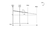
- FIG. 4 is a collinear diagram that can represent the relative relationship between the rotational speeds of the rotating elements on the straight line in the drive device of FIG. 1, corresponding to the EV-1 mode and the HV-1 mode of FIG. 3.
- FIG. 1 is a skeleton diagram illustrating a configuration of a hybrid vehicle drive device to which the present invention is preferably applied. It is a figure explaining the principal part of the control system provided in order to control the drive of the drive device of FIG.
- FIG. 2 is an engagement table showing clutch and brake engagement states in each of five types of travel modes established in the drive device of FIG. 1.
- FIG. FIG. 4 is a collinear
- FIG. 4 is a collinear diagram that can represent on a straight line the relative relationship between the rotational speeds of the rotating elements in the drive device of FIG. 1, corresponding to EV-2 of FIG. 3.
- FIG. 4 is a collinear diagram that can represent on a straight line the relative relationship between the rotational speeds of the rotating elements in the drive device of FIG. 1, corresponding to HV-2 in FIG.
- FIG. 4 is a collinear diagram that can represent on a straight line the relative relationship between the rotational speeds of the rotating elements in the drive device of FIG. 1, corresponding to HV-3 in FIG. It is a functional block diagram explaining the principal part of the control function with which the electronic control apparatus of FIG. 2 was equipped.
- FIG. 4 is a collinear diagram that can represent on a straight line the relative relationship between the rotational speeds of the rotating elements in the drive device of FIG. 1, corresponding to EV-2 of FIG. 3.
- FIG. 4 is a collinear diagram that can represent on a straight line the relative relationship between the rotational speeds of the
- FIG. 9 is a schematic diagram illustrating a configuration of a drive line from the engine to the first electric motor, which is a premise for operation in the engine start control unit of FIG. 8, and shows a drive line when the clutch is released and a drive line when the clutch is engaged.
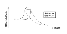
- FIG. FIG. 10 is a diagram illustrating resonance characteristics of the drive line when the clutch shown in FIG. 9 is released and the drive line when the clutch is engaged.
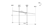
- FIG. 9 is a diagram for explaining the rise characteristic of the engine speed that is raised by the engine start control unit of FIG. 8 in comparison with the resonance speed of the drive line when the clutch is released and the resonance speed of the drive line when the clutch is engaged. is there.
- FIG. 10 is a diagram illustrating resonance characteristics of the drive line when the clutch shown in FIG. 9 is released and the drive line when the clutch is engaged.
- FIG. 9 is a flowchart for explaining a clutch switching control operation at the time of engine start in the engine start control unit of FIG. 8. It is a skeleton diagram explaining the composition of the other hybrid vehicle drive device to which the present invention is applied suitably. It is a skeleton diagram explaining the composition of still another hybrid vehicle drive device to which the present invention is preferably applied. It is a skeleton diagram explaining the composition of still another hybrid vehicle drive device to which the present invention is preferably applied. It is a skeleton diagram explaining the composition of still another hybrid vehicle drive device to which the present invention is preferably applied. It is a skeleton diagram explaining the composition of still another hybrid vehicle drive device to which the present invention is preferably applied. It is a skeleton diagram explaining the composition of still another hybrid vehicle drive device to which the present invention is preferably applied.
- the first differential mechanism and the second differential mechanism have four rotation elements as a whole when the clutch is engaged.
- the first differential mechanism and the second differential mechanism are: In the state in which the plurality of clutches are engaged, there are four rotating elements as a whole.
- the present invention relates to a first differential mechanism and a second differential mechanism that are represented as four rotating elements on the nomographic chart, an engine connected to each of the four rotating elements, a first electric motor, A second electric motor and an output rotating member, wherein one of the four rotating elements is selected by selecting the rotating element of the first differential mechanism and the rotating element of the second differential mechanism via a clutch.
- the rotating element of the first differential mechanism or the second differential mechanism to be engaged by the clutch is selectively connected to the non-rotating member via a brake.
- the present invention is suitably applied to a drive control device.
- the clutch and the brake are preferably hydraulic engagement devices whose engagement state is controlled (engaged or released) according to the hydraulic pressure, for example, a wet multi-plate friction engagement device.
- a meshing engagement device that is, a so-called dog clutch (meshing clutch) may be used.
- the engagement state may be controlled (engaged or released) according to an electrical command, such as an electromagnetic clutch or a magnetic powder clutch.
- one of a plurality of travel modes is selectively established according to the engagement state of the clutch and the brake.
- the operation of the engine is stopped and the brake is engaged and the clutch is released in an EV traveling mode in which at least one of the first electric motor and the second electric motor is used as a driving source for traveling.
- the EV-1 mode is established, and the EV-2 mode is established by engaging both the brake and the clutch.
- the brake In the hybrid travel mode in which the engine is driven and the first electric motor and the second electric motor drive or generate electric power as required, the brake is engaged and the clutch is released, so that the HV-1
- the HV-2 mode is established when the brake is released and the clutch is engaged
- the HV-3 mode is established when both the brake and the clutch are released.
- the rotation elements in the first differential mechanism and the second differential mechanism are arranged in a collinear diagram when the clutch is engaged and the brake is released.
- the order represents the first rotation element in the first differential mechanism when the rotation speeds corresponding to the second rotation element and the third rotation element in the first differential mechanism and the second differential mechanism are respectively superimposed.
- FIG. 1 is a skeleton diagram illustrating the configuration of a hybrid vehicle drive device 10 (hereinafter simply referred to as drive device 10) to which the present invention is preferably applied.
- the drive device 10 of the present embodiment is a device for horizontal use that is preferably used in, for example, an FF (front engine front wheel drive) type vehicle and the like, and an engine 12, which is a main power source, A first electric motor MG1, a second electric motor MG2, a first planetary gear device 14 as a first differential mechanism, and a second planetary gear device 16 as a second differential mechanism are provided on a common central axis CE.
- the drive device 10 is configured substantially symmetrically with respect to the center axis CE, and in FIG. 1, the lower half of the center line is omitted. The same applies to each of the following embodiments.
- the engine 12 is, for example, an internal combustion engine such as a gasoline engine that generates driving force by combustion of fuel such as gasoline that is injected into a cylinder, and via a torsional damper device 13 that absorbs the pulsation of its output torque.
- the first planetary gear unit 14 is coupled to the carrier C1.
- the first electric motor MG1 and the second electric motor MG2 are preferably so-called motor generators each having a function as a motor (engine) for generating a driving force and a generator (generator) for generating a reaction force.
- the stators (stator) 18 and 22 are fixed to a housing (case) 26 which is a non-rotating member, and rotors (rotors) 20 and 24 are provided on the inner peripheral sides of the stators 18 and 22. ing.
- the first planetary gear unit 14 is a single pinion type planetary gear unit having a gear ratio ⁇ 1, and is a carrier as a second rotation element that supports the sun gear S1 and the pinion gear P1 as the first rotation element so as to be capable of rotating and revolving.
- a ring gear R1 as a third rotating element that meshes with the sun gear S1 via C1 and the pinion gear P1 is provided as a rotating element (element).
- the second planetary gear device 16 is a single pinion type planetary gear device having a gear ratio of ⁇ 2, and is a carrier as a second rotating element that supports the sun gear S2 and the pinion gear P2 as the first rotating element so as to be capable of rotating and revolving.
- a ring gear R2 as a third rotating element that meshes with the sun gear S2 via C2 and the pinion gear P2 is provided as a rotating element (element).
- the sun gear S1 of the first planetary gear unit 14 is connected to the rotor 20 of the first electric motor MG1.
- the carrier C1 of the first planetary gear device 14 is connected to an input shaft 28 that is rotated integrally with the crankshaft of the engine 12.
- the input shaft 28 is centered on the central axis CE.
- the direction of the central axis of the central axis CE is referred to as an axial direction (axial direction) unless otherwise distinguished.
- the ring gear R1 of the first planetary gear device 14 is connected to the output gear 30 that is an output rotating member, and is also connected to the ring gear R2 of the second planetary gear device 16.
- the sun gear S2 of the second planetary gear device 16 is connected to the rotor 24 of the second electric motor MG2.
- the driving force output from the output gear 30 is transmitted to a pair of left and right drive wheels (not shown) via a differential gear device and an axle (not shown).
- torque input to the drive wheels from the road surface of the vehicle is transmitted (input) from the output gear 30 to the drive device 10 via the differential gear device and the axle.
- a mechanical oil pump 32 such as a vane pump is connected to an end of the input shaft 28 opposite to the engine 12, and hydraulic pressure that is used as a source pressure of a hydraulic control circuit 60 and the like to be described later when the engine 12 is driven. Is output.
- the carrier C1 of the first planetary gear unit 14 and the carrier C2 of the second planetary gear unit 16 are selectively engaged between the carriers C1 and C2 (disconnection between the carriers C1 and C2).
- a clutch CL is provided.
- a brake BK for selectively engaging (fixing) the carrier C2 with the housing 26 is provided between the carrier C2 of the second planetary gear device 16 and the housing 26 which is a non-rotating member.
- the clutch CL and the brake BK are preferably hydraulic engagement devices whose engagement states are controlled (engaged or released) according to the hydraulic pressure supplied from the hydraulic control circuit 60.
- a wet multi-plate friction engagement device or the like is preferably used, but a meshing engagement device, that is, a so-called dog clutch (meshing clutch) may be used.
- an engagement state may be controlled (engaged or released) according to an electrical command supplied from the electronic control device 40, such as an electromagnetic clutch or a magnetic powder clutch.
- the first planetary gear device 14 and the second planetary gear device 16 are arranged coaxially with the input shaft 28 (on the central axis CE), and the central axis CE. It arrange
- the second electric motor MG1 is disposed on the opposite side of the engine 12 with respect to the second planetary gear device 16. That is, the first electric motor MG1 and the second electric motor MG2 are arranged at positions facing each other with the first planetary gear device 14 and the second planetary gear device 16 interposed therebetween with respect to the axial direction of the central axis CE. That is, in the drive device 10, in the axial direction of the central axis CE, the first electric motor MG1, the first planetary gear device 14, the clutch CL, the second planetary gear device 16, the brake BK, and the second electric motor MG2 from the engine 12 side. In order, these components are arranged on the same axis.
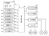
- FIG. 2 is a diagram for explaining a main part of a control system provided in the drive device 10 in order to control the drive of the drive device 10.
- the electronic control unit 40 shown in FIG. 2 includes a CPU, a ROM, a RAM, an input / output interface, and the like, and executes signal processing in accordance with a program stored in advance in the ROM while using a temporary storage function of the RAM.
- the microcomputer is a so-called microcomputer, and executes various controls related to driving of the drive device 10 including drive control of the engine 12 and hybrid drive control related to the first electric motor MG1 and the second electric motor MG2. That is, in this embodiment, the electronic control device 40 corresponds to a drive control device for a hybrid vehicle to which the drive device 10 is applied.
- the electronic control device 40 is configured as an individual control device for each control as necessary, such as for output control of the engine 12 and operation control of the first electric motor MG1 and the second electric motor MG2.
- the electronic control device 40 is configured to be supplied with various signals from sensors, switches, and the like provided in each part of the driving device 10. That is, a driver's output request is made by the operation position signal Sh output from the shift operating device 41 in response to a manual operation to a parking position, neutral position, forward travel position, reverse travel position, etc., and the accelerator opening sensor 42.
- a signal indicative of the engine rotation speed N E is the rotational speed of the engine 12 by a signal
- an engine speed sensor 44 representing the accelerator opening a CC is an operation amount of an accelerator pedal (not shown) corresponding to the amount
- the engine by the engine temperature sensor 45 temperature T E for example signals representative of the temperature of cooling water 12
- signals the MG2 rotation speed sensor 48 represents the rotational speed N MG2 of the second electric motor MG2
- the output teeth corresponding to the vehicle speed V by the output speed sensor 50 Signal representative of the rotational speed N OUT of the 30, a signal representing each wheel respective speeds N W in the driving device 10 by the wheel speed sensor 52, and the charging capacity (charging state) of the battery (not shown) by the battery SOC sensor 54 signals representative of the SOC Are supplied to the electronic control unit 40, respectively.
- the electronic control device 40 is configured to output an operation command to each part of the drive device 10. That is, as an engine output control command for controlling the output of the engine 12, a fuel injection amount signal for controlling a fuel supply amount to an intake pipe or the like by the fuel injection device, and an ignition timing (ignition timing) of the engine 12 by the ignition device are commanded.
- An electronic throttle valve drive signal and the like supplied to the throttle actuator for operating the ignition signal and the throttle valve opening ⁇ TH of the electronic throttle valve are output to an engine control device 56 that controls the output of the engine 12.
- a command signal commanding the operation of the first motor MG1 and the second motor MG2 is output to the inverter 58, and electric energy corresponding to the command signal is transmitted from the battery to the first motor MG1 and the second motor MG2 via the inverter 58.
- the output (torque) of the first electric motor MG1 and the second electric motor MG2 is controlled by being supplied. Electric energy generated by the first electric motor MG1 and the second electric motor MG2 is supplied to the battery via the inverter 58 and stored in the battery.
- a command signal for controlling the engagement state of the clutch CL and the brake BK is supplied to an electromagnetic control valve such as a linear solenoid valve provided in the hydraulic control circuit 60, and the hydraulic pressure output from the electromagnetic control valve is controlled.
- the engagement state of the clutch CL and the brake BK is controlled. Further, a command signal for locking the rotation of the output gear 30 is supplied from the electronic control unit 40 to the parking lock device (parking mechanism) 62 in response to the operation position signal Sh indicating the parking position.
- the driving device 10 functions as an electric differential unit that controls the differential state between the input rotation speed and the output rotation speed by controlling the operation state via the first electric motor MG1 and the second electric motor MG2.
- the electric energy generated by the first electric motor MG1 is supplied to the battery and the second electric motor MG2 via the inverter 58.
- the main part of the power of the engine 12 is mechanically transmitted to the output gear 30, while a part of the power is consumed for power generation by the first electric motor MG 1 and is converted into electric energy there.
- the electric energy is supplied to the second electric motor MG2.
- the second electric motor MG2 is driven and the power output from the second electric motor MG2 is transmitted to the output gear 30.
- FIG. 3 is an engagement table showing the engagement states of the clutch CL and the brake BK in each of the five types of travel modes established in the drive device 10, with the engagement indicated by “ ⁇ ” and the release indicated by a blank. Yes.
- the operation of the engine 12 is stopped, and at least one of the first electric motor MG1 and the second electric motor MG2 is used as a driving source for traveling.
- EV traveling mode used as “HV-1 mode”, “HV-2 mode”, and “HV-3 mode” are all driven by the first electric motor MG1 and the second electric motor MG2 while driving the engine 12 as a driving source for traveling, for example.
- This is a hybrid (engine) traveling mode in which driving or power generation is performed accordingly.
- a reaction force may be generated by at least one of the first electric motor MG1 and the second electric motor MG2, or may be idled in an unloaded state.
- the operation of the engine 12 is stopped, and in the EV traveling mode in which at least one of the first electric motor MG ⁇ b> 1 and the second electric motor MG ⁇ b> 2 is used as a driving source for traveling, the brake BK Is engaged and the clutch CL is disengaged, the “EV-1 mode (travel mode 1)” is achieved, and the brake BK and the clutch CL are both engaged, “EV-2 mode (travel mode 2). ) ”Is established.
- the brake BK is engaged and the clutch CL is engaged.
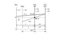
- FIGS. 4 to 7 show the rotational speeds of the rotating elements in the driving device 10 (the first planetary gear device 14 and the second planetary gear device 16) that have different coupling states depending on the engagement states of the clutch CL and the brake BK.
- a horizontal line X1 indicates zero rotation speed.
- the solid line Y1 is the sun gear S1 (first electric motor MG1) of the first planetary gear unit 14, the broken line Y2 is the sun gear S2 (second electric motor MG2) of the second planetary gear unit 16, and the solid line Y3.
- the carrier C1 (engine 12) of the first planetary gear unit 14 the broken line Y3 'is the carrier C2 of the second planetary gear unit 16
- the solid line Y4 is the ring gear R1 (output gear 30) of the first planetary gear unit 14, and the broken line Y4'.
- the relative rotational speeds of the three rotating elements in the first planetary gear device 14 are indicated by a solid line L1
- the relative rotational speeds of the three rotating elements in the second planetary gear device 16 are indicated by a broken line L2.
- the interval between the four vertical lines Y1 to Y4 (Y2 to Y4 ′) corresponding to the four rotation elements as a whole depends on the gear ratios ⁇ 1 and ⁇ 2 of the first planetary gear unit 14 and the second planetary gear unit 16. It is determined. That is, regarding the vertical lines Y1, Y3, Y4 corresponding to the three rotating elements in the first planetary gear device 14, the distance between the sun gear S1 and the carrier C1 corresponds to 1, and the distance between the carrier C1 and the ring gear R1.
- the gear ratio ⁇ 2 of the second planetary gear device 16 is preferably larger than the gear ratio ⁇ 1 of the first planetary gear device 14 ( ⁇ 2> ⁇ 1).
- the “EV-1 mode (travel mode 1)” shown in FIG. 3 is preferably a first motor travel mode in which the operation of the engine 12 is stopped and the second motor MG2 is used as a drive source for travel. is there.
- FIG. 4 is a collinear diagram corresponding to the EV-1 mode. If described using this collinear diagram, the carrier C1 and the second planet of the first planetary gear unit 14 are released by releasing the clutch CL. The gear device 16 can rotate relative to the carrier C2. By engaging the brake BK, the carrier C2 of the second planetary gear device 16 is connected (fixed) to the housing 26, which is a non-rotating member, and the number of rotations is zero.
- the rotation direction of the sun gear S2 and the rotation direction of the ring gear R2 are opposite to each other, and negative torque (torque in the negative direction) is output by the second electric motor MG2.
- the ring gear R2 that is, the output gear 30 is rotated in the positive direction by the torque. That is, by outputting negative torque by the second electric motor MG2, the hybrid vehicle to which the drive device 10 is applied can travel forward. In this case, the first electric motor MG1 is idled.
- FIG. 5 is a collinear diagram corresponding to the EV-2 mode. If the collinear diagram is used to explain, the carrier C1 and the second planetary gear device 14 of the first planetary gear unit 14 are engaged by engaging the clutch CL. The planetary gear device 16 cannot be rotated relative to the carrier C2.
- the carrier C2 of the second planetary gear device 16 and the carrier C1 of the first planetary gear device 14 engaged with the carrier C2 are connected to the housing 26 which is a non-rotating member. (Fixed), and its rotation speed is zero.
- the rotation direction of the sun gear S1 and the rotation direction of the ring gear R1 are opposite to each other, and in the second planetary gear device 16, the rotation direction of the sun gear S2 and the ring gear are reversed.
- the direction of rotation of R2 is the opposite direction.
- the hybrid vehicle to which the drive device 10 is applied can be moved forward or backward by at least one of the first electric motor MG1 and the second electric motor MG2.
- a mode in which power generation is performed by at least one of the first electric motor MG1 and the second electric motor MG2 can be established.
- torque limitation due to heat it is possible to run to ease restrictions such as torque limitation due to heat.
- the EV-2 mode it is possible to perform EV traveling under a wide range of traveling conditions, or to perform EV traveling continuously for a long time. Therefore, the EV-2 mode is suitably employed in a hybrid vehicle having a high ratio of EV traveling such as a plug-in hybrid vehicle.
- the “HV-1 mode (travel mode 3)” shown in FIG. 3 is preferably used as a drive source for travel when the engine 12 is driven, and the first motor MG1 and the second motor MG2 are used as necessary.
- This is a first hybrid (engine) traveling mode in which driving or power generation is performed.
- the collinear diagram of FIG. 4 also corresponds to the HV-1 mode. If described with reference to this collinear diagram, the carrier C1 and the first planetary gear unit 14 of the first planetary gear unit 14 are released by releasing the clutch CL. The two planetary gear unit 16 can rotate relative to the carrier C2.
- the carrier C2 of the second planetary gear device 16 is connected (fixed) to the housing 26, which is a non-rotating member, and the number of rotations is zero.
- the engine 12 is driven, and the output gear 30 is rotated by the output torque.
- the output torque from the engine 12 can be transmitted to the output gear 30 by causing the first electric motor MG 1 to output the reaction torque.
- the rotation direction of the sun gear S2 and the rotation direction of the ring gear R2 are opposite because the brake BK is engaged. That is, when negative torque (negative direction torque) is output by the second electric motor MG2, the ring gears R1 and R2, that is, the output gear 30 are rotated in the positive direction by the torque.
- the “HV-2 mode (travel mode 4)” shown in FIG. 3 is preferably used as a drive source for travel when the engine 12 is driven, and the first electric motor MG1 and the second electric motor MG2 as required.
- This is a second hybrid (engine) traveling mode in which driving or power generation is performed.
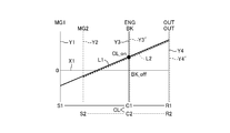
- FIG. 6 is a collinear diagram corresponding to the HV-2 mode. If described using this collinear diagram, the carrier C1 and the second planetary gear device 14 of the first planetary gear unit 14 are engaged by engaging the clutch CL. The planetary gear device 16 is not allowed to rotate relative to the carrier C2, and operates as one rotating element that rotates the carriers C1 and C2 integrally.
- the ring gears R1 and R2 Since the ring gears R1 and R2 are connected to each other, the ring gears R1 and R2 operate as one rotating element that is rotated integrally. That is, in the HV-2 mode, the rotating elements in the first planetary gear device 14 and the second planetary gear device 16 in the drive device 10 function as a differential mechanism including four rotating elements as a whole. That is, four gears in order from the left in FIG. 6 are the sun gear S1 (first electric motor MG1), the sun gear S2 (second electric motor MG2), the carriers C1 and C2 (engine 12) connected to each other, A composite split mode is obtained in which ring gears R1 and R2 (output gear 30) connected to each other are connected in this order.
- the arrangement order of the rotating elements in the first planetary gear device 14 and the second planetary gear device 16 is preferably the sun gear S1 indicated by the vertical line Y1.
- the sun gear S2 indicated by the vertical line Y2, the carriers C1 and C2 indicated by the vertical line Y3 (Y3 ′), and the ring gears R1 and R2 indicated by the vertical line Y4 (Y4 ′) are arranged in this order.
- the gear ratios ⁇ 1 and ⁇ 2 of the first planetary gear device 14 and the second planetary gear device 16 are respectively represented by a vertical line Y1 corresponding to the sun gear S1 and a vertical line Y2 corresponding to the sun gear S2, as shown in FIG.
- the interval between the vertical lines Y1 and Y3 is larger than the interval between the vertical lines Y2 and Y3 ′.
- the distance between the sun gears S1, S2 and the carriers C1, C2 corresponds to 1
- the distance between the carriers C1, C2 and the ring gears R1, R2 corresponds to ⁇ 1, ⁇ 2.
- the gear ratio ⁇ 2 of the second planetary gear device 16 is larger than the gear ratio ⁇ 1 of the first planetary gear device 14.
- the reaction force can be applied to the output of the engine 12 by either the first electric motor MG1 or the second electric motor MG2. That is, when the engine 12 is driven, the reaction force can be shared by one or both of the first electric motor MG1 and the second electric motor MG2, and the engine 12 can be operated at an efficient operating point, or the torque caused by heat. It is possible to run to ease restrictions such as restrictions.
- the efficiency can be improved by controlling the first motor MG1 and the second motor MG2 to receive the reaction force preferentially by the motor that can operate efficiently.
- the driving force is assisted by regeneration or output of an electric motor that is not torque limited, so that the engine 12 It is possible to ensure a reaction force necessary for driving.
- the “HV-3 mode (travel mode 5)” shown in FIG. 3 is preferably used as a drive source for driving when the engine 12 is driven, and the first electric motor MG1 generates power and continuously shifts.
- This is a third hybrid (engine) travel mode in which the ratio is variable and the operating point of the engine 12 is operated along a preset optimum curve.
- FIG. 7 is a collinear diagram corresponding to the HV-3 mode. If described using this collinear diagram, the carrier C1 and the second planet of the first planetary gear unit 14 are released by releasing the clutch CL.
- the gear device 16 can rotate relative to the carrier C2.
- the carrier C2 of the second planetary gear device 16 can rotate relative to the housing 26, which is a non-rotating member.
- the second electric motor MG2 can be disconnected from the drive system (power transmission path) and stopped.
- the second electric motor MG2 is always rotated with the rotation of the output gear 30 (ring gear R2) when the vehicle is traveling.
- the rotation speed of the second electric motor MG2 reaches a limit value (upper limit value), the rotation speed of the ring gear R2 is increased and transmitted to the sun gear S2, etc. Therefore, it is not always preferable to always rotate the second electric motor MG2 at a relatively high vehicle speed from the viewpoint of improving efficiency.
- the second electric motor MG2 is driven by the engine 12 and the first electric motor MG1 by separating the second electric motor MG2 from the drive system at a relatively high vehicle speed, so that the second electric motor MG2 is driven.
- the maximum rotation speed upper limit value
- the engine 12 is driven and used as a driving source for traveling, and driving or power generation is performed by the first electric motor MG1 and the second electric motor MG2 as necessary.
- three modes of the HV-1 mode, the HV-2 mode, and the HV-3 mode can be selectively established by a combination of engagement and release of the clutch CL and the brake BK.
- the mode with the highest transmission efficiency among these three modes according to the vehicle speed, the gear ratio, etc. of the vehicle it is possible to improve the transmission efficiency and thus improve the fuel efficiency. it can.
- FIG. 8 is a functional block diagram for explaining the main part of the control function of the electronic control unit 40 of FIG.
- the engine start request determination unit 70 determines whether or not there has been a request to start the engine 12 from a state where the engine 12 is stopped (a state where fuel injection and ignition are not performed from the engine control device 56). . For example, when the SOC of the power storage device (not shown) falls below the lower limit value and the storage amount is insufficient, when the travel mode selection device (not shown) is switched to the engine travel position, the required drive calculated from the accelerator opening and the vehicle speed It is determined that a start request for the engine 12 has been made, for example, when the force exceeds a predetermined determination value and enters the engine travel region.
- the parking state determination unit 72 determines whether or not the parking position is selected by the shift operation device 41 and the rotation of the output gear 30 is locked by the parking lock device 62, for example, whether or not a command signal is output from the parking lock device 62. Determine based on.
- the mode determination unit 74 determines whether one of the five modes, EV-1 mode, EV-2 mode, HV-1 mode, HV-2 mode, and HV-3 mode, is established, the vehicle speed V and the accelerator opening A. The determination is made based on vehicle parameters such as CC , SOC, operating temperature, the output state of the engine control device 56 and the inverter 58, the output state of the mode switching control unit 76, or an already set flag.
- the mode switching control unit 76 determines and switches the traveling mode to be established in the drive device 10. For example, based on whether the required driving force of the driver determined based on the vehicle speed V and the accelerator opening degree A CC is a preset electric traveling region or engine traveling region, or based on a request based on the SOC Then, it is determined whether it is electric traveling or hybrid traveling. When the electric travel is selected or requested, one of the EV-1 mode and the EV-2 mode is selected based on the request based on the SOC or the driver's selection. When hybrid driving is selected or requested, the HV-1 mode and HV-2 mode are used so that the driving force and the fuel consumption are compatible based on the efficiency and transmission efficiency of the engine 12, the magnitude of the required driving force, etc.
- HV-3 mode For example, establishment of HV-1 mode 3 is selected for low gears at low vehicle speeds (high reduction ratio range), and HV- for medium gears at medium vehicle speeds (medium reduction ratio range) or high gears at high vehicle speeds (reduction speed ratio range).
- the establishment of the two mode is selected.
- the mode switching control unit 76 releases the clutch CL and engages the brake BK via the hydraulic control circuit 60. Thereby, the state shown in the alignment chart of FIG. 6 is changed to the state shown in the alignment chart of FIG.
- the engine start control unit 78 determines that the engine start request is determined by the engine start request determination unit 70 and the parking state determination unit 72 determines that the output gear 30 is mechanically blocked from being parked. Once, together to start the increase in the rotational speed, ie, the engine rotational speed N E of the crankshaft of the engine 12 by the first electric motor MG1, the fuel injection and control of the ignition or the like into the intake pipe or the like to the engine 12 to the engine control unit 56 To start.
- the engine start control unit 78 is configured to release the brake BK, in cranking to launch engine rotational speed N E by the first electric motor MG1, the first planetary gear via a torsion damper device 13 from the engine 12
- the engagement state of the clutch CL is switched so that the vibration (resonance) of the drive line DL reaching the first electric motor MG1 connected to the sun gear S1 of the device (differential mechanism) 14 is suppressed.
- FIG. 9 shows the first motor connected to the sun gear S1 of the first planetary gear device (differential mechanism) 14 from the engine 12 via the torsional damper device 13 when the P position is selected.
- the drive line DL reaching MG1 is equivalently shown as a torsional vibration system. If the clutch CL is in the released state, the second electric motor MG2 is disengaged, so that the vibration system shown in the upper part of FIG. 9 is obtained, but when the clutch CL is engaged, the inertia of the rotor of the second electric motor MG2 is the vibration system. It is shown as a vibration system shown in the lower stage added to the right end of. In the vibration system shown in the upper stage, assuming that the vibration characteristic shown by the solid line in FIG.
- the vibration system shown in the lower stage has a characteristic in which the vibration peak, that is, the resonance point is lowered as shown by the broken line.
- the resonance frequency of the upper vibration system in which the clutch CL is released is about 13 Hz
- the resonance frequency of the lower vibration system in which the clutch CL is engaged is about 10 Hz.
- These resonance frequencies of 10 Hz and 13 Hz correspond to, for example, 300 rpm and 390 rpm when converted to the resonance rotational speeds NR1on and NR1off related to the primary fluctuation of the explosion of the 4-cycle 4-cylinder engine, for example, the rotational 0.5-order fluctuation of the 4-cycle 4-cylinder engine.
- the values correspond to 1200 rpm and 1560 rpm.
- These residence rotational speed is, for example, a rotational speed of the minimum inclination of the portion of the curve showing the rise of the engine speed N E in the first half A and the second half B, a engine 12 low order associated with engine friction There is a property that decreases.
- the engine rotational speed N E in the first half period A until the initial explosion the rotation fluctuation of the compressed primary frequency explosion primary frequency i.e. every 180 ° of the engine 12 includes an engine in the latter period within the B after the first explosion the rotational speed N E include rotation 0.5th varies due to unstable ignition. Therefore, in case of not performing switching control of the clutch CL at the time of engine starting, engine rotational speed at the rise of the N E, torsional damper device which is designed to absorb the rotational fluctuation for starting the engine 12 Since the resonance frequency of the drive line DL including 13 coincides with or is close to the resonance rotational speeds NR1 and NR2 in the first half section A and the second half section B, there is a problem that vibration and sound continue for a relatively long time. It was easy.
- the engine start control unit 78 a first dwell rotation speed NT1 that is formed in rising the first half A of the engine rotational speed N E, the temperature T E of the engine 12 from the relationship stored in advance experimentally determined
- the first staying rotational speed calculation unit 80 calculated based on the first staying rotational speed NT1 calculated by the first staying rotational speed calculation unit 80, the first resonance rotational speed NR1on of the drive line DL set in advance, and The first resonance rotation for selecting one of the first resonance rotation speed NR1on and NR1off so that, for example, the larger one of the difference rotation speeds (NT1-NR1on) and (NT1-NR1off) can be obtained from NR1off
- the number selection determination unit 82 and the resonance speed of the drive line DL in the first half period A are selected by the first resonance speed selection determination unit 82.
- a first clutch changeover control unit 84 for the clutch CL engaged or released for one to become one of the first resonance rotational speed NR1on and NR1off is, first formed in the rising latter half B of the engine rotational speed N E 2 retention rotational speed NT2, a second dwell speed calculating unit 86 that calculates, based on the relationship stored in advance experimentally determined temperature T E of the engine 12, by the second dwell speed calculating section 86 From the calculated second staying rotational speed NT2 and preset second resonant rotational speeds NR2on and NR2off of the drive line DL, for example, a larger one of the differential rotational speeds (NT2-NR2on) and (NT2-NR2off) The second resonance rotation speed selection for selecting one of the second resonance rotation speeds NR2on and NR2off
- the clutch CL is engaged so that the resonance speed of the drive line DL in the second half period B becomes one of the second resonance speed NR2on and NR2off selected by the second resonance speed selection determination section 88.
- FIG. 12 is a flowchart for explaining a main part of the control operation of the electronic control unit 40 of FIG.
- This flowchart is an engine start-time clutch switching routine that is executed when an engine start request is made in a state where the rotation of the output gear 30 is locked by the parking lock device 62.
- step S1 corresponding to the first dwell speed calculating section 80 (hereinafter abbreviated step) in, prior to the rise of the engine speed N E, formed in rising the first half A of the engine rotational speed N E first dwell rotation speed NT1 that is, is calculated from a pre-stored relationship is experimentally determined based on the temperature T E of the engine 12.
- the resonance rotation speed of the drive line DL in the first half period A is the first resonance rotation speed NR1on and NR1off selected by the first resonance rotation speed selection determination section 82.
- the clutch CL is engaged or released so as to be one of them.
- step S5 corresponds to the second dwell speed calculating section 86, second residence rotational speed NT2 formed in the rising latter half B of the engine speed N E, a predetermined stored relationship is experimentally determined It is calculated based on the temperature T E of the engine 12.
- the inertia of the rotor of the second electric motor MG2 is added to the inertia of the drive line DL, and the first resonance speed NR1 or the second resonance speed NR2 of the drive line DL is decreased.
- the clutch CL is released, the inertia of the rotor of the second electric motor MG2 is subtracted from the drive line DL, and the first resonance speed NR1 or the second resonance speed NR2 of the drive line DL is increased.
- the first retention rotation speed NT1 that is formed in rising the first half A of the rotational speed N E of the engine 12, the torsional damper 13 from the engine 12
- the clutch CL is switched so that the larger value of (NT1-NR1on) and (NT1-NR1off) is obtained.
- the second retention rotational speed NT2 formed in the rising latter half B of the engine rotational speed N E, via a torsional damper 13 from the engine 12
- the engagement state of the clutch CL is switched so that, for example, a larger value of the differential rotation speeds (NT2-NR2on) and (NT2-NR2off) is obtained from the rotation.
- first retention rotational speed NT1 and the second dwell rotational speed NT2 is calculated based on the temperature T E of the engine 12 from a pre-stored relationship The Therefore, since the first dwell rotational speed NT1 and the second dwell rotational speed NT2 displaced according to the temperature T E of the engine 12 is accurately determined, the occurrence of resonance is precisely avoided has been sound and vibration drive line DL is Effectively suppressed.
- the vehicle stops, and the output gear (output rotation member) 30 is locked in the non-rotation state by the parking parking lock device 62. ing.
- the reaction force generated when the engine speed of the first electric motor rises is received by the parking lock mechanism, so that even if the clutch engagement state is switched, it does not appear as a change in the driving force of the vehicle.
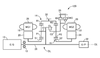
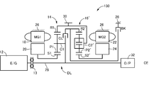
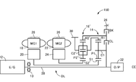
- the drive control device for a hybrid vehicle according to the present invention like the drive device 100 shown in FIG. 13 and the drive device 110 shown in FIG. 14, has the first electric motor MG1, the first planetary gear device 14, and the second drive device in the direction of the central axis CE.
- the present invention is also preferably applied to a configuration in which the arrangement (arrangement) of the electric motor MG2, the second planetary gear device 16, the clutch CL, and the brake BK is changed.
- the carrier C2 is allowed to rotate in one direction with respect to the housing 26 between the carrier C2 of the second planetary gear device 16 and the housing 26 that is a non-rotating member.
- the present invention is also preferably applied to a configuration in which a one-way clutch (one-way clutch) OWC that prevents reverse rotation is provided in parallel with the brake BK.
- the present invention is also preferably applied to a configuration including a pinion type second planetary gear device 16 '.
- the second planetary gear device 16 ' includes a sun gear S2' as a first rotating element, a carrier C2 'as a second rotating element that supports a plurality of pinion gears P2' meshed with each other so as to be capable of rotating and revolving, and a pinion gear P2. And a ring gear R2 'as a third rotating element that meshes with the sun gear S2' via the 'as a rotating element (element).
- the hybrid vehicle drive device 100, 110, 120, 130, 140, 150 of the second embodiment is connected to the sun gear S1 as the first rotating element connected to the first electric motor MG1 and the engine 12.
- a first planetary gear unit 14 as a first differential mechanism including a carrier C1 as a second rotation element and a ring gear R1 as a third rotation element coupled to an output gear 30 as an output rotation member; and a second electric motor
- a sun gear S2 (S2 ') as a first rotating element coupled to MG2, a carrier C2 (C2') as a second rotating element, and a ring gear R2 (R2 ') as a third rotating element, these carriers C2 (C2 ′) and the ring gear R2 (R2 ′) are either a second differential mechanism in which one of the ring gears R2 (R2 ′) is connected to the ring gear R1 of the first planetary gear unit 14.
- FIGS. 19 to 21 illustrate the configuration and operation of other hybrid vehicle drive devices 160, 170, and 180 to which the present invention is preferably applied in place of the hybrid vehicle drive device 10 of the first embodiment.
- FIG. As described above, the relative rotational speeds of the sun gear S1, the carrier C1, and the ring gear R1 in the first planetary gear unit 14 are indicated by solid lines L1, and the relative speeds of the sun gear S2, the carrier C2, and the ring gear R2 in the second planetary gear unit 16 are compared. The number of revolutions is indicated by a broken line L2.
- the sun gear S1, the carrier C1, and the ring gear R1 of the first planetary gear device 14 are connected to the first electric motor MG1, the engine 12, and the second electric motor MG2, respectively, and the sun gear of the second planetary gear device 16 is connected.
- S2, carrier C2 and ring gear R2 are connected to non-rotating member 26 via second electric motor MG2, output rotating member 30 and brake BK, respectively, and sun gear S1 and ring gear R2 are selectively connected via clutch CL.
- the sun gear S1, the carrier C1, and the ring gear R1 of the first planetary gear device 14 are connected to the first electric motor MG1, the output rotating member 30, and the engine 12, respectively.
- S2, carrier C2 and ring gear R2 are connected to non-rotating member 26 via second electric motor MG2, output rotating member 30 and brake BK, respectively, and sun gear S1 and ring gear R2 are selectively connected via clutch CL. ing.
- the sun gear S1, the carrier C1, and the ring gear R1 of the first planetary gear device 14 are connected to the first electric motor MG1, the output rotating member 30, and the engine 12, respectively, and the sun gear of the second planetary gear device 16 is connected.
- S2, carrier C2 and ring gear R2 are connected to non-rotating member 26 and output rotating member 30 via second electric motor MG2 and brake BK, respectively, and ring gear R1 and carrier C2 are selectively connected via clutch CL. ing.
- the first planetary gear device 14 and the second planetary gear device 16 (16 ′) having four rotation elements as a whole on the alignment chart. Therefore, by providing each of the electronic control devices 40 of the first embodiment, the same effects as those of the first embodiment can be obtained. For example, is switched engagement state of the clutch CL, as in cranking to launch engine rotational speed N E, the resonance of the drive line DL which is excited by the rotation fluctuation of the engine 12 is not generated for starting the engine 12 Therefore, during the cranking, vibration of the drive line DL from the engine 12 to the first electric motor MG1 connected to the differential mechanism via the torsional damper 13 is suitably suppressed.
- the first differential mechanism (first planetary gear unit 14) having four rotation elements as a whole and the second difference are shown on the collinear chart.
- the element and the rotating element of the second differential mechanism (second planetary gear device 16, 16 ') are selectively connected via the clutch CL, and the brake BK and the clutch CL are engaged to make the first Electric motor MG1 and second electric
- it is a drive control device for a hybrid vehicle motor running is performed to drive the vehicle in machine MG2, it is common.
- the switching control of the clutch CL for suppressing vibration of the drive line DL may be executed in one of the second half B.
- the clutch CL for suppressing the vibration of the drive line DL, for example, the first staying rotational speed NT1 formed in the first half A of the rising speed of the rotational speed of 12 and the engine 12 via the torsional damper 13
- the clutch CL has been switched so as to obtain a larger side.
- This clutch CL is not only switched from the engaged state to the released state, but also in the released state. May be switched from the engaged state to the engaged state.
- Hybrid vehicle drive device 12 Engine 13: Torsional damper 14: First planetary gear device (first differential mechanism) 16, 16 ': Second planetary gear device (second differential mechanism) 30: Output gear (output rotating member) 40: Electronic control device (drive control device) 62: Parking lock device (parking mechanism) 70: Engine start request determination unit 78: Engine start control unit 80: First staying rotational speed calculation unit 82: First resonance rotational speed selection determination unit 84: First clutch switching control unit 86: Second staying rotational speed calculation unit 88 : Second resonance rotational speed selection determination unit 90: second clutch switching control unit BK: brake CL: clutches C 1, C 2, C 2 ′: carrier (second rotational element) MG1: first electric motor MG2: second electric motor R1, R2, R2 ': ring gear (third rotating element) S1, S2, S2 ': Sun gear (first rotating element) DL: Drive line NT1: First staying speed NT2: Second
Landscapes
- Engineering & Computer Science (AREA)
- Transportation (AREA)
- Mechanical Engineering (AREA)
- Chemical & Material Sciences (AREA)
- Combustion & Propulsion (AREA)
- Power Engineering (AREA)
- Automation & Control Theory (AREA)
- Sustainable Development (AREA)
- Sustainable Energy (AREA)
- Life Sciences & Earth Sciences (AREA)
- Electric Propulsion And Braking For Vehicles (AREA)
- Hybrid Electric Vehicles (AREA)
- Control Of Vehicle Engines Or Engines For Specific Uses (AREA)
Abstract
Priority Applications (5)
| Application Number | Priority Date | Filing Date | Title |
|---|---|---|---|
| PCT/JP2012/057811 WO2013145092A1 (fr) | 2012-03-26 | 2012-03-26 | Dispositif de commande de conduite pour véhicule hybride |
| JP2014507063A JP5874813B2 (ja) | 2012-03-26 | 2012-03-26 | ハイブリッド車両の駆動制御装置 |
| CN201280071823.2A CN104203698B (zh) | 2012-03-26 | 2012-03-26 | 混合动力车辆的驱动控制装置 |
| DE201211006101 DE112012006101T5 (de) | 2012-03-26 | 2012-03-26 | Antriebssteuervorrichtung für ein Hybridfahrzeug |
| US14/387,603 US9248831B2 (en) | 2012-03-26 | 2012-03-26 | Drive control device for hybrid vehicle |
Applications Claiming Priority (1)
| Application Number | Priority Date | Filing Date | Title |
|---|---|---|---|
| PCT/JP2012/057811 WO2013145092A1 (fr) | 2012-03-26 | 2012-03-26 | Dispositif de commande de conduite pour véhicule hybride |
Publications (1)
| Publication Number | Publication Date |
|---|---|
| WO2013145092A1 true WO2013145092A1 (fr) | 2013-10-03 |
Family
ID=49258462
Family Applications (1)
| Application Number | Title | Priority Date | Filing Date |
|---|---|---|---|
| PCT/JP2012/057811 Ceased WO2013145092A1 (fr) | 2012-03-26 | 2012-03-26 | Dispositif de commande de conduite pour véhicule hybride |
Country Status (5)
| Country | Link |
|---|---|
| US (1) | US9248831B2 (fr) |
| JP (1) | JP5874813B2 (fr) |
| CN (1) | CN104203698B (fr) |
| DE (1) | DE112012006101T5 (fr) |
| WO (1) | WO2013145092A1 (fr) |
Cited By (1)
| Publication number | Priority date | Publication date | Assignee | Title |
|---|---|---|---|---|
| CN106184216A (zh) * | 2014-12-26 | 2016-12-07 | 现代自动车株式会社 | 混合动力车辆的减振控制装置 |
Families Citing this family (8)
| Publication number | Priority date | Publication date | Assignee | Title |
|---|---|---|---|---|
| KR101683516B1 (ko) * | 2015-09-25 | 2016-12-07 | 현대자동차 주식회사 | 하이브리드 차량의 엔진 클러치 전달토크 학습방법 및 그 학습장치 |
| CN106853819B (zh) * | 2015-12-09 | 2019-05-24 | 上海汽车集团股份有限公司 | 一种hcu及离合器工作模式切换的控制方法 |
| JP6536543B2 (ja) | 2016-11-17 | 2019-07-03 | トヨタ自動車株式会社 | 車両用制御装置 |
| US10015596B1 (en) * | 2017-03-21 | 2018-07-03 | GM Global Technology Operations LLC | Engine sound audio control systems and methods based on intake and/or exhaust temperature |
| JP6780566B2 (ja) * | 2017-04-04 | 2020-11-04 | トヨタ自動車株式会社 | ハイブリッド自動車 |
| JP6900908B2 (ja) | 2018-01-09 | 2021-07-07 | トヨタ自動車株式会社 | 車両用制御装置 |
| JP2020175850A (ja) * | 2019-04-22 | 2020-10-29 | マツダ株式会社 | 車両のパワートレイン装置 |
| NL2025138B1 (en) * | 2020-03-16 | 2021-10-19 | Daf Trucks Nv | Power management system for electrical vehicles |
Citations (6)
| Publication number | Priority date | Publication date | Assignee | Title |
|---|---|---|---|---|
| JP2005199942A (ja) * | 2004-01-19 | 2005-07-28 | Toyota Motor Corp | 動力出力装置およびこれを搭載する自動車並びに動力伝達装置 |
| JP2007118718A (ja) * | 2005-10-26 | 2007-05-17 | Toyota Motor Corp | 車両用駆動装置の制御装置 |
| JP2009215952A (ja) * | 2008-03-10 | 2009-09-24 | Nissan Motor Co Ltd | エンジン始動制御装置及び始動制御方法並びにエンジン制御方法とエンジン |
| JP2009215958A (ja) * | 2008-03-10 | 2009-09-24 | Nissan Motor Co Ltd | エンジン始動制御装置及び始動制御方法並びにエンジン制御方法とエンジン |
| JP2011213179A (ja) * | 2010-03-31 | 2011-10-27 | Honda Motor Co Ltd | ハイブリッド車両の動力制御装置 |
| JP2011230521A (ja) * | 2010-04-23 | 2011-11-17 | Toyota Motor Corp | 始動制御装置 |
Family Cites Families (20)
| Publication number | Priority date | Publication date | Assignee | Title |
|---|---|---|---|---|
| US4887490A (en) * | 1988-07-14 | 1989-12-19 | Sundstrand Corporation | Sequential mechanical mode shifter |
| US5034893A (en) * | 1989-04-10 | 1991-07-23 | Clean Air Technologies, Inc. | Graphical display of timing advance data |
| US6683389B2 (en) * | 2000-06-30 | 2004-01-27 | Capstone Turbine Corporation | Hybrid electric vehicle DC power generation system |
| US6397963B1 (en) * | 2000-10-31 | 2002-06-04 | Ford Global Technologies, Inc. | Method and arrangement in a hybrid vehicle for maintaining a catalyst in an effective state |
| US6336063B1 (en) * | 2000-10-31 | 2002-01-01 | Volvo Car Corporation | Method and arrangement in a hybrid vehicle for improving battery state-of-charge control and minimizing driver perceptible disturbances |
| US6512967B2 (en) * | 2000-10-31 | 2003-01-28 | Volvo Car Corporation | Method and arrangement in a hybrid vehicle for maximizing total torque output by minimizing differential torque capacities of the engine and generator |
| US6500089B2 (en) * | 2000-10-31 | 2002-12-31 | Ford Global Technologies, Inc. | Method and arrangement in a hybrid vehicle for maximizing efficiency by operating the engine at sub-optimum conditions |
| US6755266B2 (en) * | 2000-10-31 | 2004-06-29 | Volvo Car Corporation | Method and arrangement in a hybrid vehicle for initiating early engine operation during take-off conditions |
| US6453222B1 (en) * | 2000-10-31 | 2002-09-17 | Volvo Car Corporation | Method and arrangement in a hybrid vehicle for matching engine and generator torques at times of engagement and disengagement |
| DE10256993B4 (de) * | 2001-12-06 | 2018-05-09 | Denso Corporation | Steuergerät für eine Brennkraftmaschine |
| JP3956796B2 (ja) * | 2001-12-26 | 2007-08-08 | アイシン・エィ・ダブリュ株式会社 | ハイブリッド型車両駆動制御装置、ハイブリッド型車両駆動制御方法及びそのプログラム |
| JP3700710B2 (ja) * | 2003-05-09 | 2005-09-28 | 日産自動車株式会社 | ハイブリッド車両の駆動制御装置 |
| JP4062264B2 (ja) * | 2003-06-06 | 2008-03-19 | アイシン・エィ・ダブリュ株式会社 | 車両駆動制御装置、車両駆動制御方法及びプログラム |
| US7217221B2 (en) * | 2004-05-14 | 2007-05-15 | General Motors Corporation | Method for active engine stop of a hybrid electric vehicle |
| US20080243322A1 (en) * | 2007-03-30 | 2008-10-02 | Mazda Motor Corporation | Control device and method of hybrid vehicle |
| JP4412346B2 (ja) * | 2007-04-20 | 2010-02-10 | トヨタ自動車株式会社 | ハイブリッド車両の駆動制御装置 |
| JP2008265600A (ja) | 2007-04-23 | 2008-11-06 | Toyota Motor Corp | 車両およびその制御方法 |
| JP4743218B2 (ja) * | 2008-03-03 | 2011-08-10 | 日産自動車株式会社 | ハイブリッド車両のクラッチ制御装置 |
| RU2014102260A (ru) | 2011-07-27 | 2015-09-10 | Тойота Дзидося Кабусики Кайся | Приводной механизм гибридного транспортного средства |
| JP6114255B2 (ja) | 2012-03-21 | 2017-04-12 | トヨタ自動車株式会社 | ハイブリッド車両の駆動制御装置 |
-
2012
- 2012-03-26 DE DE201211006101 patent/DE112012006101T5/de not_active Ceased
- 2012-03-26 WO PCT/JP2012/057811 patent/WO2013145092A1/fr not_active Ceased
- 2012-03-26 JP JP2014507063A patent/JP5874813B2/ja not_active Expired - Fee Related
- 2012-03-26 CN CN201280071823.2A patent/CN104203698B/zh not_active Expired - Fee Related
- 2012-03-26 US US14/387,603 patent/US9248831B2/en not_active Expired - Fee Related
Patent Citations (6)
| Publication number | Priority date | Publication date | Assignee | Title |
|---|---|---|---|---|
| JP2005199942A (ja) * | 2004-01-19 | 2005-07-28 | Toyota Motor Corp | 動力出力装置およびこれを搭載する自動車並びに動力伝達装置 |
| JP2007118718A (ja) * | 2005-10-26 | 2007-05-17 | Toyota Motor Corp | 車両用駆動装置の制御装置 |
| JP2009215952A (ja) * | 2008-03-10 | 2009-09-24 | Nissan Motor Co Ltd | エンジン始動制御装置及び始動制御方法並びにエンジン制御方法とエンジン |
| JP2009215958A (ja) * | 2008-03-10 | 2009-09-24 | Nissan Motor Co Ltd | エンジン始動制御装置及び始動制御方法並びにエンジン制御方法とエンジン |
| JP2011213179A (ja) * | 2010-03-31 | 2011-10-27 | Honda Motor Co Ltd | ハイブリッド車両の動力制御装置 |
| JP2011230521A (ja) * | 2010-04-23 | 2011-11-17 | Toyota Motor Corp | 始動制御装置 |
Cited By (2)
| Publication number | Priority date | Publication date | Assignee | Title |
|---|---|---|---|---|
| CN106184216A (zh) * | 2014-12-26 | 2016-12-07 | 现代自动车株式会社 | 混合动力车辆的减振控制装置 |
| CN106184216B (zh) * | 2014-12-26 | 2019-08-16 | 现代自动车株式会社 | 混合动力车辆的减振控制装置 |
Also Published As
| Publication number | Publication date |
|---|---|
| CN104203698B (zh) | 2016-12-21 |
| CN104203698A (zh) | 2014-12-10 |
| JP5874813B2 (ja) | 2016-03-02 |
| US20150321661A1 (en) | 2015-11-12 |
| US9248831B2 (en) | 2016-02-02 |
| JPWO2013145092A1 (ja) | 2015-08-03 |
| DE112012006101T5 (de) | 2015-01-08 |
Similar Documents
| Publication | Publication Date | Title |
|---|---|---|
| JP5874813B2 (ja) | ハイブリッド車両の駆動制御装置 | |
| JP5967105B2 (ja) | ハイブリッド車両の駆動制御装置 | |
| JP5846219B2 (ja) | ハイブリッド車両の駆動制御装置 | |
| WO2013088501A1 (fr) | Dispositif de commande d'entraînement pour véhicule hybride | |
| JP5884897B2 (ja) | ハイブリッド車両の駆動制御装置 | |
| JP5874812B2 (ja) | ハイブリッド車両の駆動制御装置 | |
| JP5874814B2 (ja) | ハイブリッド車両の駆動制御装置 | |
| WO2013140540A1 (fr) | Dispositif de commande d'entraînement pour véhicule hybride | |
| WO2013140546A1 (fr) | Dispositif de commande d'entraînement pour véhicule hybride | |
| WO2013145099A1 (fr) | Dispositif de commande d'entraînement pour véhicule hybride | |
| JP5971330B2 (ja) | ハイブリッド車両の駆動制御装置 | |
| JP5884893B2 (ja) | ハイブリッド車両の駆動制御装置 | |
| CN104859423A (zh) | 混合动力车辆用驱动装置的控制装置 | |
| WO2013145089A1 (fr) | Dispositif de commande d'entraînement pour véhicule hybride | |
| WO2013145090A1 (fr) | Dispositif de commande d'entraînement pour véhicule hybride | |
| WO2013145091A1 (fr) | Dispositif de commande d'entraînement de véhicule hybride | |
| WO2013145095A1 (fr) | Dispositif de contrôle de conduite de véhicule hybride | |
| JP2013203388A (ja) | ハイブリッド車両の駆動制御装置 | |
| JP2013203386A (ja) | ハイブリッド車両の駆動制御装置 | |
| JP2013203385A (ja) | ハイブリッド車両の駆動制御装置 | |
| JPWO2013088501A1 (ja) | ハイブリッド車両の駆動制御装置 | |
| JPWO2013145090A1 (ja) | ハイブリッド車両の駆動制御装置 | |
| JPWO2013140546A1 (ja) | ハイブリッド車両の駆動制御装置 | |
| JPWO2013145089A1 (ja) | ハイブリッド車両の駆動制御装置 | |
| JPWO2013145091A1 (ja) | ハイブリッド車両の駆動制御装置 |
Legal Events
| Date | Code | Title | Description |
|---|---|---|---|
| 121 | Ep: the epo has been informed by wipo that ep was designated in this application |
Ref document number: 12872727 Country of ref document: EP Kind code of ref document: A1 |
|
| WWE | Wipo information: entry into national phase |
Ref document number: 14387603 Country of ref document: US |
|
| ENP | Entry into the national phase |
Ref document number: 2014507063 Country of ref document: JP Kind code of ref document: A |
|
| WWE | Wipo information: entry into national phase |
Ref document number: 1120120061012 Country of ref document: DE Ref document number: 112012006101 Country of ref document: DE |
|
| 122 | Ep: pct application non-entry in european phase |
Ref document number: 12872727 Country of ref document: EP Kind code of ref document: A1 |