WO2013145497A1 - Composition de résine durcissable aux ultraviolets et revêtement esthétique - Google Patents
Composition de résine durcissable aux ultraviolets et revêtement esthétique Download PDFInfo
- Publication number
- WO2013145497A1 WO2013145497A1 PCT/JP2012/084152 JP2012084152W WO2013145497A1 WO 2013145497 A1 WO2013145497 A1 WO 2013145497A1 JP 2012084152 W JP2012084152 W JP 2012084152W WO 2013145497 A1 WO2013145497 A1 WO 2013145497A1
- Authority
- WO
- WIPO (PCT)
- Prior art keywords
- resin composition
- coating film
- coating
- curable resin
- layer
- Prior art date
- Legal status (The legal status is an assumption and is not a legal conclusion. Google has not performed a legal analysis and makes no representation as to the accuracy of the status listed.)
- Ceased
Links
Images


Classifications
-
- C—CHEMISTRY; METALLURGY
- C09—DYES; PAINTS; POLISHES; NATURAL RESINS; ADHESIVES; COMPOSITIONS NOT OTHERWISE PROVIDED FOR; APPLICATIONS OF MATERIALS NOT OTHERWISE PROVIDED FOR
- C09D—COATING COMPOSITIONS, e.g. PAINTS, VARNISHES OR LACQUERS; FILLING PASTES; CHEMICAL PAINT OR INK REMOVERS; INKS; CORRECTING FLUIDS; WOODSTAINS; PASTES OR SOLIDS FOR COLOURING OR PRINTING; USE OF MATERIALS THEREFOR
- C09D5/00—Coating compositions, e.g. paints, varnishes or lacquers, characterised by their physical nature or the effects produced; Filling pastes
- C09D5/28—Coating compositions, e.g. paints, varnishes or lacquers, characterised by their physical nature or the effects produced; Filling pastes for wrinkle, crackle, orange-peel, or similar decorative effects
-
- C—CHEMISTRY; METALLURGY
- C08—ORGANIC MACROMOLECULAR COMPOUNDS; THEIR PREPARATION OR CHEMICAL WORKING-UP; COMPOSITIONS BASED THEREON
- C08F—MACROMOLECULAR COMPOUNDS OBTAINED BY REACTIONS ONLY INVOLVING CARBON-TO-CARBON UNSATURATED BONDS
- C08F2/00—Processes of polymerisation
- C08F2/46—Polymerisation initiated by wave energy or particle radiation
- C08F2/48—Polymerisation initiated by wave energy or particle radiation by ultraviolet or visible light
-
- C—CHEMISTRY; METALLURGY
- C08—ORGANIC MACROMOLECULAR COMPOUNDS; THEIR PREPARATION OR CHEMICAL WORKING-UP; COMPOSITIONS BASED THEREON
- C08F—MACROMOLECULAR COMPOUNDS OBTAINED BY REACTIONS ONLY INVOLVING CARBON-TO-CARBON UNSATURATED BONDS
- C08F20/00—Homopolymers and copolymers of compounds having one or more unsaturated aliphatic radicals, each having only one carbon-to-carbon double bond, and only one being terminated by only one carboxyl radical or a salt, anhydride, ester, amide, imide or nitrile thereof
- C08F20/02—Monocarboxylic acids having less than ten carbon atoms, Derivatives thereof
- C08F20/10—Esters
- C08F20/20—Esters of polyhydric alcohols or polyhydric phenols, e.g. 2-hydroxyethyl (meth)acrylate or glycerol mono-(meth)acrylate
Definitions
- the present invention relates to an ultraviolet curable resin composition and a design coating film capable of giving a beautiful design.
- Patent Document 1 There has been proposed a coating composition that uses a sulfonic acid neutralized with a large excess of a secondary amine as a curing catalyst, and forms a paint film having a wrinkle pattern using the curing catalytic action (for example, Patent Document 1). reference.).
- a hammer tone paint in which fine particles of a vinyl polymer antifoaming agent act on the surface of a coating film to form a hammer tone pattern has been proposed (see, for example, Patent Document 2).
- a paint to which a volatile flake such as aluminum powder or a pearl pigment is added is spray-coated as fine droplets, and then the same or the same quality paint as this paint is applied to this liquid.
- a coating giving a three-dimensional effect can be formed by spray coating as droplets larger than droplets (see, for example, Patent Document 3).
- the paint composition described in Patent Document 1 is exemplified by plastics in addition to metals, wood, cement, etc. as the object to be coated, but the maximum material temperature during curing is 120 to 260 ° C. for 5 seconds. It is necessary to perform the treatment for ⁇ 30 minutes, and in reality, it is limited to those having heat resistance.
- the paint described in Patent Document 2 has a problem that the solid content concentration must be within a predetermined range in order to form a pattern, and adjustment is troublesome.
- the coating method described in Patent Document 3 requires special techniques such as adjustment of spray pressure. So far, a composition or a coating method has been proposed that can form a pattern having a highly designed and three-dimensional appearance without requiring special operations such as adjustment of solid content concentration and adjustment of spray pressure. Absent.
- An object of the present invention is to provide an ultraviolet curable resin composition and a design coating film capable of applying a beautiful design having a three-dimensional appearance without requiring a special operation regardless of the heat resistance of an object to be coated. Is to provide.
- the present inventors can form a coating film having a network pattern by a general operation in ultraviolet curing by using a specific monomer or oligomer and a specific photopolymerization initiator in combination with the resin composition.
- the ultraviolet curable resin composition according to the present invention includes at least one selected from an acrylate monomer, an acrylate oligomer, and an acrylic acid oligomer, a benzophenone photopolymerization initiator, an aminobenzoate light as a photopolymerization initiator. It contains at least one selected from a polymerization initiator and an ⁇ -hydroxyalkylphenone photopolymerization initiator.
- the acrylate monomer is preferably an ester of (meth) acrylic acid and a polyol. It can be appropriately cured to form a mesh pattern efficiently.
- the ester of (meth) acrylic acid and polyol is modified bisphenol A diacrylate, modified bisphenol F diacrylate, pentaerythritol triacrylate, dipentaerythritol hexaacrylate, or trimethylol. It is preferably at least one of propane triacrylate.
- a paint film having a clearer pattern and higher design can be formed.
- the content of the photopolymerization initiator is 0.5 to 40 parts by mass with respect to 100 parts by mass of the acrylate monomer, the acrylate oligomer, and the acrylic acid oligomer. It is preferable that A coating film having high adhesion and good curability and pattern formation can be formed.
- the content of the acrylate monomer, the acrylate oligomer, and the acrylic acid oligomer is 40 to 100 parts by mass with respect to 100 parts by mass of the coating film component. preferable.
- An effective mesh pattern can be formed.
- the designable coating film according to the present invention is a designable coating film provided with a coating layer obtained by applying and curing the ultraviolet curable resin composition according to the present invention on the surface of an object to be coated, wherein the coating layer is a mesh. It has a pattern.
- the coating layer is divided into a 5 mm ⁇ 5 mm square lattice pattern, and at least one of the divided 5 mm ⁇ 5 mm square regions has 2 to 200 small sections depending on the mesh pattern. It is preferable to be divided into two. It can be a more beautiful design.
- the coating layer is an undercoat layer, and a top coat layer is further provided on the surface of the undercoat layer.
- Various designs can be given.
- the surface smoothness of the coating film can be increased. Moreover, durability can be improved.
- a metal layer is further provided between the undercoat layer and the topcoat layer. Furthermore, it can be set as a beautiful metallic design.
- the present invention provides an ultraviolet curable resin composition and a design coating film capable of applying a beautiful design having a three-dimensional appearance without requiring a special operation regardless of the heat resistance of an object to be coated. can do.
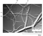
- FIG. 2 is a SEM image showing a surface state and a cross-sectional state of a coating layer of the designable coating film of Example 1.
- FIG. 2 is an SEM image showing a surface state and a cross-sectional state of a top coat layer of the designable coating film of Example 1.
- the ultraviolet curable resin composition according to the present embodiment includes at least one selected from an acrylate monomer, an acrylate oligomer, and an acrylic acid oligomer, a benzophenone photopolymerization initiator, and an aminobenzoate photopolymerization photopolymerization initiator. And one or more selected from an initiator and an ⁇ -hydroxyalkylphenone photopolymerization initiator.
- the acrylate monomer is an ester of (meth) acrylic acid, and is a component that forms a network pattern by polymerization and curing by irradiation with ultraviolet rays.
- (meth) acrylic acid includes acrylic acid and methacrylic acid.
- the acrylate monomer is preferably an ester of (meth) acrylic acid and a polyol.
- a polyol is a compound having two or more hydroxyl groups in the molecule, and includes polyhydric alcohols and polyhydric phenols.
- the polyhydric alcohol is, for example, pentaerythritol, dipentaerythritol, trimethylolpropane, dipropylene glycol, 1,6-hexanediol, tripropylene glycol, polyethylene glycol, neopentyl glycol, tricyclodecane dimethanol, glycerin or ditrimethylol. Propane or a modified product thereof.
- the polyhydric phenol is, for example, bisphenol A, bisphenol F, or a modified product thereof.
- the modified product is, for example, an ethylene oxide (EO) modified product or a propylene oxycide (PO) modified product.
- Esters of acrylic acid and polyol are, for example, bisphenol A di (meth) acrylate, modified bisphenol A di (meth) acrylate, bisphenol F di (meth) acrylate, modified bisphenol F di (meth) acrylate, pentaerythritol tri (meth) ) Acrylate, dipentaerythritol hexa (meth) acrylate, trimethylolpropane tri (meth) acrylate, dipropylene glycol di (meth) acrylate, 1,6-hexanediol di (meth) acrylate, tripropylene glycol di (meth) acrylate , Polyethylene glycol di (meth) acrylate, neopentyl glycol di (meth) acrylate, modified neopentyl glycol di (meth) acrylate, tricyclodecane dimeta Di (meth) acrylate, neopentyl glycol hydroxypivalate
- Esters of acrylic acid and polyol can be cured moderately and efficiently form a network pattern, so that modified bisphenol A diacrylate, modified bisphenol F diacrylate, pentaerythritol triacrylate (PETIA), diester It is preferably at least one of pentaerythritol hexaacrylate (DPHA) and trimethylolpropane triacrylate (TMPTA).
- the modified bisphenol A diacrylate or the modified bisphenol F diacrylate is more preferably an EO-modified product.
- the acrylate oligomer is, for example, a urethane acrylate oligomer or a polyester acrylate oligomer. Among these, a polyester acrylate oligomer is more preferable.
- An acrylate oligomer may be used individually by 1 type, or may use 2 or more types together.
- acrylic acid oligomer examples include acrylic acid dimer, ⁇ -caprolactone-modified tris (acryloxyethyl) isocyanurate, and trisacryloyloxyethyl isocyanurate.
- a benzophenone photopolymerization initiator is a component that initiates a polymerization reaction of an acrylate monomer, an acrylate oligomer, or an acrylic acid oligomer by irradiation with ultraviolet rays.
- the benzophenone photopolymerization initiator is a compound having a benzophenone skeleton, and examples thereof include benzophenone, 4-methylbenzophenone, 4,4'-bis (dimethylamino) benzophenone, and 4,4'-bis (diethylamino) benzophenone.
- aminobenzoate-based photopolymerization initiator examples include 2-ethylhexyl-4-dimethylaminobenzoate and ethyl-4-dimethylaminobenzoate.
- the ⁇ -hydroxyalkylphenone photopolymerization initiator is, for example, 1-hydroxy-cyclohexyl-phenyl-ketone.
- the content of the photopolymerization initiator is 0.5 to 40 parts by mass with respect to 100 parts by mass of the acrylate monomer, the acrylate oligomer, and the acrylic acid oligomer. Is preferred.
- the amount is more preferably 0.5 to 30 parts by mass, still more preferably 1 to 15 parts by mass, and particularly preferably 2 to 6 parts by mass. If it is less than 0.5 mass part, it may be inferior to sclerosis
- the content of the photopolymerization initiator is the total mass of the acrylate monomers, acrylate oligomers and acrylic acid oligomers.
- the content is relative to 100 parts by mass.
- the ultraviolet curable resin composition preferably further contains an acrylic resin.
- the acrylic resin mainly has a role as an anti-repellent agent.
- the acrylic resin itself is a non-polymerizable resin having no polymerization reactivity, and is a polymer or copolymer of an acrylate ester or a methacrylate ester.
- the ultraviolet curable resin composition may further contain various additives such as a leveling agent, a pigment, a dye, and a stabilizer.
- the leveling agent is, for example, a fluorine-based leveling agent or a silicon-based leveling agent.
- a fluorine-based leveling agent is preferable because it does not affect the adhesion of the topcoat layer.
- the ultraviolet curable resin composition can further contain a light stabilizer.
- the light stabilizer has a role of relaxing the progress inside the coating film and making the pattern appear more stably when the peak intensity at the time of curing is too high.
- the light stabilizer is, for example, an ultraviolet absorber (UVA) such as a hindered amine light stabilizer (HALS), a benzotriazole (BTZ) ultraviolet absorber, or a triazine (HPT) ultraviolet absorber. More preferably, HALS and UVA are used in combination.
- the light stabilizer is preferably 3% by mass or less, more preferably 1% by mass or less, relative to the coating film component. When it exceeds 3 mass%, adhesiveness with a base material may fall.
- the ultraviolet curable resin composition preferably further contains a solvent.
- the solvent mainly has a role as a medium for proceeding the polymerization reaction, a role for uniformly dissolving or dispersing the coating film component, a role as a diluent for adjusting the viscosity suitable for the coating work, and a role for adjusting curability.
- the solvent include acetone (AT) (boiling point 56.3 ° C.), ethyl acetate (EAC) (boiling point 77.1 ° C.), methyl ethyl ketone (MEK) (boiling point 79.5 ° C.) and the like having a boiling point of 100 ° C. or less.
- low boiling point solvent methyl isobutyl ketone (MIBK) (boiling point 116.7 ° C.), butyl acetate (BAC) (boiling point 126.3 ° C.), isobutyl alcohol (I-BOH) (boiling point 108 ° C.), Solvents with boiling points exceeding 100 ° C. and below 150 ° C.
- MIBK methyl isobutyl ketone
- BAC butyl acetate
- I-BOH isobutyl alcohol
- TO toluene
- DIBK diisobutyl ketone
- IBIB isobutyl isobutyrate
- butyl cellosolve buticero
- isophorone boiling point 215.2 ° C.
- a solvent may be used independently or may use 2 or more types together.
- a low-boiling solvent mixed with a medium-boiling solvent or a high-boiling solvent from the viewpoint that the photocurability of the acrylate monomer, acrylate oligomer or acrylic acid oligomer can be improved.
- the boiling point (1 atm) of the solvent is preferably 50 to 200 ° C. More preferably, it is 50 to 130 ° C. If it is less than 50 degreeC, it may be inferior to coating workability
- the content of the acrylate monomer, the acrylate oligomer, and the acrylic acid oligomer is preferably 40 to 100 parts by mass with respect to 100 parts by mass of the coating film component. More preferably, it is 70 to 100 parts by mass.
- the coating film component refers to a component remaining as a coating layer, in other words, a component excluding a component that volatilizes during the formation of the coating layer in the ultraviolet curable resin composition.
- the component that volatilizes when the coating layer is formed is, for example, a solvent.
- FIG. 1 is a photographed image by a microscope showing a first example of the coating layer.
- FIG. 2 is a photographed image by a microscope showing a second example of the coating layer.
- the designable coating film according to the present embodiment is a designable coating film including a coating layer obtained by applying and curing the ultraviolet curable resin composition according to the present embodiment on the surface of an object to be coated, and FIG. As shown in 2, the coating layer has a mesh pattern.
- the material of the object to be coated is not particularly limited.
- ABS acrylonitrile butadiene styrene copolymer
- PP polypropylene
- PA polyamide
- PC polycarbonate
- PPE polyphenylene ether
- PET polyethylene terephthalate
- PBT polybutylene terephthalate
- PMMA polymethyl methacrylate
- POM polyacetal
- the shape of the object to be coated is not particularly limited.
- parts of home appliances such as a casing, buttons, panels, keyboards, etc., mobile phones or personal computers, handles, door knobs, buttons, dashboards, engine covers, wheel caps, etc. Car interior and exterior parts.
- the design coating film is formed on the outer surface, the inner surface, or the entire surface. In addition, you may surface-treat for the purpose of improving the adhesiveness with the designable coating film on the surface of a to-be-coated article.
- the surface of the object to be coated preferably has a property of not reflecting ultraviolet rays.
- the surface of the coated material reflects ultraviolet rays, double curing in which the curing reaction proceeds not only with incident light but also with reflected light occurs, and the pattern may not be formed stably.
- Examples of the form in which the surface of the object to be coated has a property of not reflecting ultraviolet rays include a form in which the object to be coated transmits ultraviolet light or a form in which the object to be coated absorbs ultraviolet light.
- the coating layer is made of a photocured product of the ultraviolet curable resin composition according to the present embodiment, and has a mesh pattern as shown in FIG. 1 or FIG.
- the mesh pattern is a pattern formed by randomly extending concave, convex, or crack-like linear portions, and the portions where the linear portions intersect with other linear portions to form a mesh and other lines Including the part where the extension stops without crossing the shape part.
- FIG. 3 shows a state in which the coating layer of FIG. 1 is divided into a 5 mm ⁇ 5 mm square grid.
- the coating layer is divided into a 5 mm ⁇ 5 mm square lattice, and a divided 5 mm ⁇ 5 mm square region (hereinafter referred to as a unit region).
- At least one is preferably divided into 2 to 200 small sections by a mesh pattern. More preferably, it is divided into 3 to 150 small sections. If it is less than 2, it is difficult to say that a beautiful mesh pattern is formed. When the number exceeds 200, it is difficult to visually recognize the mesh pattern, and it is difficult to say that the design is high.
- a unit area is divided into small sections by a mesh pattern means that a linear part intersects with another linear part in the unit area and is divided into small sections, and the linear part crosses the unit area. It is divided into small sections. More specifically, referring to FIG. 3, the unit area denoted by A1 is divided into two small sections by a mesh pattern. The unit area marked with A2 is divided into four small sections by a mesh pattern. Moreover, the unit area
- the ratio of the number of unit regions divided into small sections by a mesh pattern to the total number of unit regions on the coating layer is preferably 50% or more, more preferably 100%, That is, all unit areas are divided into small sections by a mesh pattern.
- the number of unit areas on the coating layer is 108 and the number of unit areas divided into small sections by the mesh pattern is 78, so the pattern formation rate is 72%.
- the observation of the mesh pattern is preferably performed on the entire surface of the product, but if the entire product is difficult to observe, such as a large product, or if there is a specific area where the mesh pattern should be evaluated, the You may carry out about a part of surface. Further, the observation may be performed with a microscope, for example, with magnification of 10 times or 100 times, or may be visually observed.
- the average area of the mesh in the region is preferably 0.005 to 0.5 cm 2 . More preferably, it is 0.0125 to 0.2 cm 2 . If it is less than 0.005 cm 2, it is difficult to visually recognize the mesh, and it is difficult to say that the design is high. If it exceeds 0.5 cm 2 , it is difficult to say that a beautiful mesh pattern is formed.
- the region of 1 cm 2 is not limited to a 1 cm ⁇ 1 cm square, and the shape of the region is not limited as long as it has an area of 1 cm 2 .
- the mesh size of the mesh pattern can be adjusted by, for example, the type of monomer or oligomer to be selected and the boiling point of the solvent.
- the relationship between the size of the mesh and the type of monomer or oligomer is, for example, that EO-modified bisphenol A diacrylate and EO-modified bisphenol F diacrylate form a relatively small mesh pattern, and PETIA and DPHA are relatively large.
- a mesh pattern is formed.
- TMPTA forms a mesh pattern having a size that is intermediate between a small mesh and a large mesh.
- the mesh pattern is higher than when EO-modified bisphenol A diacrylate is used alone.
- the mesh can be enlarged.
- the relationship between the size of the mesh and the boiling point of the solvent has a relationship that the size of the mesh increases as the boiling point of the solvent increases. In particular, when the boiling point of the solvent is 170 ° C. or higher, a large mesh is formed.
- the large mesh is, for example, a state in which the unit area is divided into 2 to 20 small sections by a mesh pattern, and an average area of the mesh in the 1 cm 2 area is 0.05 to 5 cm 2 .
- Small mesh for example, a state in which the unit region is divided at 41 to 200 cubicle by a mesh pattern, the average area of the mesh of 1 cm 2 area in the state of 0.005 ⁇ 0.025 cm 2.
- An intermediate mesh size is, for example, in a state where the unit area is divided into 21 to 39 small sections by a mesh pattern, and the average area of the mesh in the 1 cm 2 area exceeds 0.025 cm 2 and 0.05 cm The state is less than 2 .
- the glossiness of the pattern varies depending on the boiling point of the solvent of the resin composition, the UV irradiation amount, and the type of monomer or oligomer to be blended.
- the solvent is a high-boiling solvent
- the UV irradiation amount is low and slightly uncured, or when the number of photoreactive functional groups is small and the amount of the low-reactivity monomer or oligomer is large
- FIG. As described above, the inside of the mesh is flat and glossiness is high, and the solvent is a low-boiling solvent or medium-boiling solvent, when the UV irradiation amount is high, or the number of photoreactive functional groups is large and the monomer or oligomer having high reactivity.
- the blending amount is large, a striped pattern is formed inside the mesh as shown in FIG. 2, resulting in a matte wind with low gloss.
- the thickness of the coating layer is preferably 5 to 100 ⁇ m. More preferably, it is 15 to 60 ⁇ m. If it is less than 5 ⁇ m, the mesh pattern may not be formed effectively. If it exceeds 100 ⁇ m, it takes time to cure and the productivity is poor. Moreover, it may become uncured.
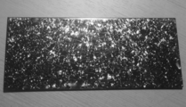
- FIG. 4 is an image showing an example of a designable coating film according to the present embodiment.
- the coating layer is an undercoat layer and a topcoat layer is further provided on the surface of the undercoat layer.
- the top coat layer mainly has a role of imparting various design properties such as color and texture, a role of improving surface smoothness, and a role of protecting the coating layer.
- the topcoat layer contains, for example, a curable resin such as an acrylic resin, a urethane resin, an acrylic urethane resin, an acrylic silicon resin, an epoxy resin, a polyester resin, or a fluorine resin.
- the topcoat layer may contain a colorant such as a colored pigment or a dye, and a bright material such as a pearl pigment or a metallic pigment.
- the topcoat layer may further contain various additives such as a leveling agent and a stabilizer. Examples of the topcoat layer include clear (colorless and transparent), color clear (colored and transparent), and solid color (single color).
- the thickness of the top coat layer is preferably 5 to 50 ⁇ m. More preferably, it is 10 to 30 ⁇ m.
- the designable coating film according to the present embodiment it is preferable to further include a metal layer between the undercoat layer (coating layer) and the topcoat layer.
- the metal of the metal layer is, for example, aluminum, tin, indium, gold, silver, copper, or chromium.
- the top coat layer is preferably clear or color clear.
- an undercoat layer (coating layer), a metal layer, and a clear topcoat layer in this order on the surface of the object to be coated a three-dimensional combination of the undercoat layer (coating layer) mesh pattern and the metallic feel of the metal layer. And, it becomes a coating film with a beautiful metallic design.
- the mesh pattern of the coating layer, the metallic feeling of the metal layer, and the color feeling of the topcoat layer By combining the two, a very beautiful coating film that is three-dimensional and metallic and has various color variations.
- the thickness of the metal layer is preferably 3 to 100 nm. More preferably, it is 10 to 70 nm.
- the design coating film has been described in the form of two or more layers in which the coating layer is an undercoat layer and the top coat layer is further provided on the surface of the undercoat layer.
- the film may have a single layer structure in which the coating layer is a top coat layer.
- the formation method of the designable coating film which concerns on this embodiment has an application layer formation process.
- the coating layer forming step includes a first coating step of coating the ultraviolet curable resin composition on the surface of the object to be coated, and a first curing step of irradiating the coating surface with ultraviolet rays to cure.
- the method of applying the ultraviolet curable resin composition is not particularly limited, and is a known method such as a brush coating method, a roller coating method, a spraying method using a spray gun, a roll coater method, or a dipping method.
- the coating layer forming step further includes a first preliminary drying step for drying the coated surface between the first coating step and the first curing step.
- the drying method is, for example, natural drying or heat drying, and heat drying is more preferable.
- the heating temperature is preferably 50 ° C. or higher and 90 ° C. or lower, and more preferably 60 ° C. or higher and 80 ° C. or lower. Below 50 ° C, the efficiency is poor. When it exceeds 90 degreeC, the smoothness of a coating film may be impaired. Further, depending on the material of the application object, deformation due to heat may occur.
- the drying time is preferably 1 minute or more and less than 20 minutes, and more preferably 2 minutes or more and 5 minutes or less. If it is less than 1 minute, the effect of preliminary drying may not be acquired. In 20 minutes or more, whitening may occur.
- the wavelength of the light source is preferably 200 to 450 nm. More preferably, it is 250 to 300 nm.
- the cumulative irradiation amount of ultraviolet rays is preferably 500 to 2000 mJ / cm 2 . More preferably, it is 600 to 1200 mJ / cm 2 . If it is less than 500 mJ / cm 2 , curing may be insufficient. If it exceeds 2000 mJ / cm 2 , a good mesh pattern may not be formed. In addition, whitening may occur due to overcuring, and the appearance may be inferior.
- the peak intensity is preferably 50 to 100 mW / cm 2 . More preferably, it is 70 to 80 mW / cm 2 .
- the irradiation time is not particularly limited because it is set according to the integrated dose and peak intensity, but as an example, it is 40 seconds when the integrated dose is 500 mJ / cm 2 and the peak intensity is 50 mW / cm 2.
- peak intensity in the irradiation amount 1000 mJ / cm 2 is 70 seconds when 80 mW / cm 2, integrated irradiation dose of 120 seconds when the peak intensity of 100 mW / cm 2 at 2000 mJ / cm 2.
- the size of the mesh of the mesh pattern can be adjusted by, for example, the integrated dose of ultraviolet rays or the peak intensity in addition to the type of monomer selected above or the boiling point of the solvent.
- the pattern becomes larger as the integrated irradiation amount of ultraviolet rays is smaller, and the pattern tends to be smaller as the integrated irradiation amount is larger. Further, the pattern tends to increase as the peak intensity decreases, and the pattern tends to decrease as the peak intensity increases.
- a network pattern having a desired size can be formed by adjusting the type of monomer to be selected, the boiling point of the solvent, the integrated dose of ultraviolet rays, and the peak intensity.
- the formation method in particular of a metal layer does not have a restriction
- the PVD method is, for example, ion plating, vacuum deposition, or sputtering.
- the plating method include an electrolytic plating method and an electroless plating method.
- the metal layer is more preferably formed by the PVD method in that the pattern can be made clearer.
- the top coat layer forming step includes a second coating step of applying a resin composition for forming the top coat layer (hereinafter referred to as a resin composition for forming a top coat layer) to the surface of the coating layer or the metal layer, and a coating surface.
- a second curing step for curing for curing.
- the coating method of the topcoat layer forming resin composition is not particularly limited, and for example, the coating methods listed in the first coating step can be used.
- the curing method is a matter selected according to the material of the topcoat layer, for example, ultraviolet curing or thermal curing. In the present embodiment, ultraviolet curing is more preferable.
- ultraviolet curing is more preferable.
- various conditions such as the wavelength of the light source, the integrated irradiation amount of ultraviolet rays, the peak intensity, and the irradiation time shown in the first curing step may be employed.
- Table 1 shows the types and names of the drugs used.
- Tables 2 to 4 show the compositions of the ultraviolet curable resin compositions of Examples and the layer structures of the design coating films.
- Tables 5 and 6 show the composition of the ultraviolet curable resin composition of the comparative example and the layer structure of the design coating film. In Tables 2 to 6, the names shown in Table 1 were used. Each layer was formed as follows.
- the coating layer was formed as follows. That is, after an ultraviolet curable resin composition is applied on an ABS plate (dimensions 10 mm ⁇ 15 mm, thickness 1 mm, model number Toughace, manufactured by Midorikawa Kasei Kogyo Co., Ltd.) by a spray coating method, the coated surface is preliminarily maintained at 60 ° C. for 3 minutes Dried. Next, using an air-cooled mercury lamp (model number H045-L31, manufactured by Eye Graphics Co., Ltd.) as an ultraviolet light source, the ultraviolet ray is irradiated for 70 seconds with an integrated irradiation amount of 1000 mJ / cm 2 and a peak intensity of 80 mW / cm 2 to be cured and dried. A coating layer was formed.
- the metal layer was formed as follows. That is, tin was vapor-deposited as a metal on the coating layer using a vacuum vapor deposition device (C-311 type vacuum vapor deposition device, Showa Vacuum Co., Ltd.) to form a metal layer.
- a vacuum vapor deposition device C-311 type vacuum vapor deposition device, Showa Vacuum Co., Ltd.
- the top coat layer was formed as follows. That is, a resin composition for forming a topcoat layer (VIOLET TOP T-390M-2, manufactured by Toho Kaken Kogyo Co., Ltd.) is applied onto a metal layer by a spray coating method, and the coated surface is pre-dried at 60 ° C. for 3 minutes. did. Next, using an air-cooled mercury lamp (model number H045-L31, manufactured by Eye Graphics Co., Ltd.) as an ultraviolet light source, the ultraviolet light is irradiated at an integrated dose of 1000 mJ / cm 2 and a peak intensity of 80 mW / cm 2 for about 1 minute to be cured and dried. A top coat layer was formed.
- VIOLET TOP T-390M-2 manufactured by Toho Kaken Kogyo Co., Ltd.
- the mesh size is obtained by dividing a captured image into a 5 mm ⁇ 5 mm square grid, and arbitrarily dividing a unit region divided into small sections by a mesh pattern from the divided 5 mm ⁇ 5 mm square region (unit region). The number of subdivisions was recorded, and the mesh size was evaluated as follows. Extra large: The unit area is divided into 2 to 5 small sections by a mesh pattern (practical level). Large: The unit area is divided into 6 to 20 small sections by a mesh pattern (practical level). Medium: The unit area is divided into 21 to 40 small sections by a mesh pattern (practical level). Small: The unit area is divided into 41 to 80 small sections by a mesh pattern (practical level).
- the unit area is divided into 81 to 200 small sections by a mesh pattern (practical level).
- NA1 There is no unit area divided into small sections by a mesh pattern (practical unsuitable level).
- NA2 The unit area is divided into 201 or more subdivisions by a mesh pattern, and the visibility is inferior (practical inappropriate level).
- Average area of mesh For the average area of the mesh, an area of 1 cm 2 was arbitrarily selected so as to include one or more meshes in the captured image, and the average area of the mesh in the area was obtained.
- Example 1 ⁇ Observation of surface state and cross-sectional state> (Coating layer)
- the surface state after the formation of the coating layer was observed obliquely from above at a magnification of 200 using a scanning electron microscope (model: JSM-5500LV, manufactured by JEOL Ltd.)
- the cross-sectional state was observed from the side at double magnification.
- a photographed SEM image is shown in FIG.
- fine irregularities were formed on the surface of the coating layer.
- Example 1 In Example 1, the surface state of the portion where the mesh pattern after the formation of the topcoat layer was formed was observed obliquely from above at a magnification of 800 times and the cross-sectional state from right side at a magnification of 500 times using a scanning electron microscope. . A photographed SEM image is shown in FIG. As shown in FIG. 6, the surface of the topcoat layer was smooth. By providing the top coat layer, it was confirmed that the appearance could be a highly smooth coating film having a three-dimensional mesh pattern.
- the mirror mat is in close contact with the member on which the coating film is formed, and is left at an atmospheric temperature of 65 ° C. and an atmospheric humidity of 95% RH for 24 hours under a load of 4.9 N. confirmed. +: The mirror mat is not transferred to the coating film or other appearance defects are not generated (practical level). -: The coating film has a migration or appearance defect (unsuitable for practical use).
- the UV curable resin compositions of Examples 1 to 20 were all photocured to form a mesh pattern. From Examples 1 to 7, it was confirmed that the size of the mesh could be adjusted by changing the type or blending ratio of the acrylate monomer used. From Examples 8 to 17, it was confirmed that the size of the mesh could be adjusted depending on the difference in the boiling point of the solvent used. Specifically, there was a tendency that the higher the boiling point of the solvent, the larger the mesh.
- UV curable resin compositions of Comparative Examples 1 to 9 all used photopolymerization initiators other than benzophenone, no net pattern was formed even when photocured.
- an ultraviolet curable resin composition was prepared using the acrylate monomers, acrylate oligomers, and acrylic acid oligomers shown in Tables 9 and 10.
- the ultraviolet curable resin composition comprises 55 parts by mass of acrylate monomers, acrylate oligomers or acrylic acid oligomers shown in Table 9 and Table 10, 30 parts by mass of ethyl acetate, and 10 parts by mass of acetone.
- 4.5 parts by mass of a benzophenone-based photopolymerization initiator and 0.5 parts by mass of a fluorine-based leveling agent (BYK340, manufactured by BYK) were prepared.
- the obtained ultraviolet curable resin composition was applied by spray coating on an ABS plate (dimensions 10 mm ⁇ 15 mm, thickness 1 mm, model number Taffece, manufactured by Midorikawa Kasei Kogyo Co., Ltd.), and then the coated surface was applied at 60 ° C. for 3 minutes. Pre-dried. Next, using an air-cooled mercury lamp (model number H045-L31, manufactured by Eye Graphics Co., Ltd.) as an ultraviolet light source, the ultraviolet ray is irradiated for 70 seconds with an integrated irradiation amount of 1000 mJ / cm 2 and a peak intensity of 80 mW / cm 2 to be cured and dried. A coating layer having a thickness of 30 ⁇ m was formed. The presence or absence of the pattern and the size of the pattern were evaluated. The evaluation results are shown in Table 9 and Table 10. As shown in Table 9 and Table 10, the ultraviolet curable resin compositions of Examples 21 to 40 were all photocured to form a network pattern.
- Example 41 57.5 parts by mass of an acrylate oligomer (Aronix M-6500, manufactured by Toagosei Co., Ltd.), 30.8 parts by mass of ethyl acetate, 10 parts by mass of acetone, an ⁇ -hydroxyalkylphenone photopolymerization initiator (1-hydroxy -Cyclohexyl-phenyl-ketone, Irgacure 184, manufactured by BASF) 1.2 parts by mass and a fluorine-based leveling agent (BYK340, manufactured by BYK) 0.5 parts by mass were prepared.
- an acrylate oligomer (Aronix M-6500, manufactured by Toagosei Co., Ltd.)
- ethyl acetate 10 parts by mass of acetone
- an ⁇ -hydroxyalkylphenone photopolymerization initiator (1-hydroxy -Cyclohexyl-phenyl-ketone, Irgacure 184, manufactured by BASF
- the obtained ultraviolet curable resin composition was applied by spray coating on an ABS plate (dimensions 10 mm ⁇ 15 mm, thickness 1 mm, model number Taffece, manufactured by Midorikawa Kasei Kogyo Co., Ltd.), and then the coated surface was applied at 60 ° C. for 3 minutes. Pre-dried. Then, air-cooled mercury lamp (Model H045-L31, Eye manufactured by Graphics Inc.) as an ultraviolet light source with ultraviolet and integrated irradiation amount 1500 mJ / cm 2, and cured and dried by irradiation for 70 seconds with a peak intensity 80 mW / cm 2 A coating layer was formed. The pattern appeared and the size of the pattern was large.
- Example 42 In Example 41, a coating layer was formed in the same manner as in Example 41 except that the integrated irradiation amount of ultraviolet rays was changed to 2000 mJ / cm 2 . The pattern appeared and the pattern size was small.
- Example 43 The coating layer was the same as in Example 1 except that the photopolymerization initiator in Example 1 was changed to a liquid aminobenzoate photopolymerization initiator (2-ethylhexyl-4-dimethylaminobenzoate, Darocur EHA, manufactured by BASF). Formed. The pattern appeared and the size of the pattern was large.
- Example 44 In Example 1, the coating layer was formed in the same manner as in Example 1 except that the photopolymerization initiator was changed to a liquid aminobenzoate-based photopolymerization initiator (ethyl-4-dimethylaminobenzoate, Darocur EDB, manufactured by BASF). did. The pattern appeared and the size of the pattern was large.
- a liquid aminobenzoate-based photopolymerization initiator ethyl-4-dimethylaminobenzoate, Darocur EDB, manufactured by BASF.
Landscapes
- Chemical & Material Sciences (AREA)
- Organic Chemistry (AREA)
- Polymers & Plastics (AREA)
- Health & Medical Sciences (AREA)
- Chemical Kinetics & Catalysis (AREA)
- Medicinal Chemistry (AREA)
- Materials Engineering (AREA)
- Wood Science & Technology (AREA)
- Engineering & Computer Science (AREA)
- Life Sciences & Earth Sciences (AREA)
- Laminated Bodies (AREA)
- Paints Or Removers (AREA)
- Addition Polymer Or Copolymer, Post-Treatments, Or Chemical Modifications (AREA)
- Macromonomer-Based Addition Polymer (AREA)
- Polymerisation Methods In General (AREA)
Abstract
L'objectif de la présente invention est de proposer une composition de résine durcissable aux ultraviolets et un revêtement esthétique avec lequel il est possible d'appliquer une conception esthétique avec une apparence tridimensionnelle sans aucun processus spécial indépendamment de la résistance à la chaleur de l'objet à recouvrir. Cette composition de résine durcissable aux ultraviolets comprend un type ou plusieurs choisis parmi un monomère à base d'acrylate, un oligomère à base d'acrylate et un oligomère à base d'acide acrylique, et un type ou plus d'un photo-initiateur choisi parmi un photo-initiateur à base de benzophénone, un photo-initiateur à base d'aminobenzoate et un photo-initiateur à base d'α-hydroxyalkylphénone. En outre, ce revêtement esthétique comprend une couche de revêtement qui est obtenue par revêtement et durcissement de la composition de résine durcissable aux ultraviolets sur la surface d'un objet à recouvrir, la couche de revêtement ayant une conception tissée.
Priority Applications (1)
| Application Number | Priority Date | Filing Date | Title |
|---|---|---|---|
| JP2013531812A JP5467302B1 (ja) | 2012-03-29 | 2012-12-28 | 紫外線硬化性樹脂組成物及び意匠性塗膜 |
Applications Claiming Priority (2)
| Application Number | Priority Date | Filing Date | Title |
|---|---|---|---|
| JP2012-075964 | 2012-03-29 | ||
| JP2012075964 | 2012-03-29 |
Publications (1)
| Publication Number | Publication Date |
|---|---|
| WO2013145497A1 true WO2013145497A1 (fr) | 2013-10-03 |
Family
ID=49258826
Family Applications (1)
| Application Number | Title | Priority Date | Filing Date |
|---|---|---|---|
| PCT/JP2012/084152 Ceased WO2013145497A1 (fr) | 2012-03-29 | 2012-12-28 | Composition de résine durcissable aux ultraviolets et revêtement esthétique |
Country Status (2)
| Country | Link |
|---|---|
| JP (1) | JP5467302B1 (fr) |
| WO (1) | WO2013145497A1 (fr) |
Cited By (10)
| Publication number | Priority date | Publication date | Assignee | Title |
|---|---|---|---|---|
| JP2016084597A (ja) * | 2014-10-24 | 2016-05-19 | 株式会社日本製鋼所 | 自動車用のドアハンドルの製造方法およびドアハンドル |
| JP2019094506A (ja) * | 2013-01-17 | 2019-06-20 | サン ケミカル コーポレイション | 紙および板紙用のecプライマーコーティング |
| KR20200025050A (ko) * | 2018-08-29 | 2020-03-10 | (주)엘지하우시스 | 내오염성 및 논슬립성이 우수한 바닥재 |
| KR20200027138A (ko) * | 2018-09-04 | 2020-03-12 | (주)엘지하우시스 | 표면에 방사형 굴곡 구조를 갖고, 내요오드성이 우수한 비발포식 바닥재 |
| KR20200027139A (ko) * | 2018-09-04 | 2020-03-12 | (주)엘지하우시스 | 표면에 방사형 굴곡 구조를 갖는 저광택의 비발포식 바닥재 |
| KR20200032878A (ko) * | 2018-09-19 | 2020-03-27 | (주)엘지하우시스 | 내스크래치성 및 논슬립성이 우수한 바닥재 |
| WO2021149480A1 (fr) * | 2020-01-22 | 2021-07-29 | 凸版印刷株式会社 | Feuille décorative, plaque décorative et procédé de fabrication de feuille décorative |
| JP2021137990A (ja) * | 2020-03-03 | 2021-09-16 | 凸版印刷株式会社 | 化粧シート、化粧板及び化粧シートの製造方法 |
| JP2022040128A (ja) * | 2020-03-03 | 2022-03-10 | 凸版印刷株式会社 | 化粧シート及び化粧板 |
| JP2022159391A (ja) * | 2020-03-03 | 2022-10-17 | 凸版印刷株式会社 | 化粧シート及び化粧板 |
Families Citing this family (5)
| Publication number | Priority date | Publication date | Assignee | Title |
|---|---|---|---|---|
| KR102140971B1 (ko) * | 2018-04-19 | 2020-08-04 | (주)엘지하우시스 | 표면에 방사형 굴곡 구조를 갖는 저광택 경화물 |
| KR102271747B1 (ko) * | 2018-09-13 | 2021-07-01 | (주)엘지하우시스 | 인쇄 특성이 우수한 장식재 및 이의 제조방법 |
| KR102405876B1 (ko) * | 2018-11-22 | 2022-06-07 | (주)엘엑스하우시스 | 내오염성 및 심미적 효과가 우수한 장식재 및 이의 제조방법 |
| KR102608459B1 (ko) * | 2018-11-23 | 2023-12-04 | (주)엘엑스하우시스 | 내스크래치성 및 내오염성이 우수한 장식재 및 이의 제조방법 |
| KR102467560B1 (ko) * | 2019-10-10 | 2022-11-17 | (주)엘엑스하우시스 | 내오염성이 뛰어난 바닥재 |
Citations (6)
| Publication number | Priority date | Publication date | Assignee | Title |
|---|---|---|---|---|
| JPH04120115A (ja) * | 1989-12-22 | 1992-04-21 | Union Carbide Chem & Plast Co Inc | アミン含有光硬化性組成物 |
| JPH06312495A (ja) * | 1993-04-28 | 1994-11-08 | Iwasaki Electric Co Ltd | 板体のシボ形成構造 |
| JPH0953024A (ja) * | 1995-08-10 | 1997-02-25 | Dainippon Ink & Chem Inc | 艶消し表面形成用樹脂組成物及び艶消し表面の形成方法 |
| JP2002275205A (ja) * | 2001-03-21 | 2002-09-25 | Kawamura Inst Of Chem Res | 表面に周期性の皺模様を有する樹脂成形物の製造方法 |
| JP2006152114A (ja) * | 2004-11-29 | 2006-06-15 | Mitsubishi Rayon Co Ltd | 光硬化性樹脂組成物およびその硬化膜を有する積層体の製造方法 |
| JP2007211094A (ja) * | 2006-02-08 | 2007-08-23 | Mitsubishi Rayon Co Ltd | 錫膜のアンダーコート層成形用組成物、錫膜のアンダーコート層及び錫膜被覆樹脂成型品 |
-
2012
- 2012-12-28 JP JP2013531812A patent/JP5467302B1/ja active Active
- 2012-12-28 WO PCT/JP2012/084152 patent/WO2013145497A1/fr not_active Ceased
Patent Citations (6)
| Publication number | Priority date | Publication date | Assignee | Title |
|---|---|---|---|---|
| JPH04120115A (ja) * | 1989-12-22 | 1992-04-21 | Union Carbide Chem & Plast Co Inc | アミン含有光硬化性組成物 |
| JPH06312495A (ja) * | 1993-04-28 | 1994-11-08 | Iwasaki Electric Co Ltd | 板体のシボ形成構造 |
| JPH0953024A (ja) * | 1995-08-10 | 1997-02-25 | Dainippon Ink & Chem Inc | 艶消し表面形成用樹脂組成物及び艶消し表面の形成方法 |
| JP2002275205A (ja) * | 2001-03-21 | 2002-09-25 | Kawamura Inst Of Chem Res | 表面に周期性の皺模様を有する樹脂成形物の製造方法 |
| JP2006152114A (ja) * | 2004-11-29 | 2006-06-15 | Mitsubishi Rayon Co Ltd | 光硬化性樹脂組成物およびその硬化膜を有する積層体の製造方法 |
| JP2007211094A (ja) * | 2006-02-08 | 2007-08-23 | Mitsubishi Rayon Co Ltd | 錫膜のアンダーコート層成形用組成物、錫膜のアンダーコート層及び錫膜被覆樹脂成型品 |
Cited By (19)
| Publication number | Priority date | Publication date | Assignee | Title |
|---|---|---|---|---|
| JP2019094506A (ja) * | 2013-01-17 | 2019-06-20 | サン ケミカル コーポレイション | 紙および板紙用のecプライマーコーティング |
| JP2016084597A (ja) * | 2014-10-24 | 2016-05-19 | 株式会社日本製鋼所 | 自動車用のドアハンドルの製造方法およびドアハンドル |
| KR20200025050A (ko) * | 2018-08-29 | 2020-03-10 | (주)엘지하우시스 | 내오염성 및 논슬립성이 우수한 바닥재 |
| KR102180634B1 (ko) | 2018-08-29 | 2020-11-18 | (주)엘지하우시스 | 내오염성 및 논슬립성이 우수한 바닥재 |
| KR20200027138A (ko) * | 2018-09-04 | 2020-03-12 | (주)엘지하우시스 | 표면에 방사형 굴곡 구조를 갖고, 내요오드성이 우수한 비발포식 바닥재 |
| KR20200027139A (ko) * | 2018-09-04 | 2020-03-12 | (주)엘지하우시스 | 표면에 방사형 굴곡 구조를 갖는 저광택의 비발포식 바닥재 |
| KR102269522B1 (ko) | 2018-09-04 | 2021-06-25 | (주)엘지하우시스 | 표면에 방사형 굴곡 구조를 갖는 저광택의 비발포식 바닥재 |
| KR102180633B1 (ko) | 2018-09-04 | 2020-11-18 | (주)엘지하우시스 | 표면에 방사형 굴곡 구조를 갖고, 내요오드성이 우수한 비발포식 바닥재 |
| KR102269523B1 (ko) | 2018-09-19 | 2021-06-25 | (주)엘지하우시스 | 내스크래치성 및 논슬립성이 우수한 바닥재 |
| KR20200032878A (ko) * | 2018-09-19 | 2020-03-27 | (주)엘지하우시스 | 내스크래치성 및 논슬립성이 우수한 바닥재 |
| WO2021149480A1 (fr) * | 2020-01-22 | 2021-07-29 | 凸版印刷株式会社 | Feuille décorative, plaque décorative et procédé de fabrication de feuille décorative |
| JP2021137990A (ja) * | 2020-03-03 | 2021-09-16 | 凸版印刷株式会社 | 化粧シート、化粧板及び化粧シートの製造方法 |
| JP2021137806A (ja) * | 2020-03-03 | 2021-09-16 | 凸版印刷株式会社 | 化粧シートの製造方法 |
| JP2022040128A (ja) * | 2020-03-03 | 2022-03-10 | 凸版印刷株式会社 | 化粧シート及び化粧板 |
| JP7044982B2 (ja) | 2020-03-03 | 2022-03-31 | 凸版印刷株式会社 | 化粧シート、化粧板及び化粧シートの製造方法 |
| JP7052901B2 (ja) | 2020-03-03 | 2022-04-12 | 凸版印刷株式会社 | 化粧シートの製造方法 |
| JP2022159391A (ja) * | 2020-03-03 | 2022-10-17 | 凸版印刷株式会社 | 化粧シート及び化粧板 |
| JP7215558B2 (ja) | 2020-03-03 | 2023-01-31 | 凸版印刷株式会社 | 化粧シート及び化粧板 |
| JP7272501B2 (ja) | 2020-03-03 | 2023-05-12 | 凸版印刷株式会社 | 化粧シート及び化粧板 |
Also Published As
| Publication number | Publication date |
|---|---|
| JP5467302B1 (ja) | 2014-04-09 |
| JPWO2013145497A1 (ja) | 2015-12-10 |
Similar Documents
| Publication | Publication Date | Title |
|---|---|---|
| JP5467302B1 (ja) | 紫外線硬化性樹脂組成物及び意匠性塗膜 | |
| JP5960088B2 (ja) | 紫外線硬化性樹脂組成物及び塗膜 | |
| TW201233743A (en) | Curable composition for coating comprising fluorine-containing highly branched polymer | |
| TW201637896A (zh) | 用於真空成形之三維成型品裝飾用積層膜、其製造方法及三維成型品裝飾方法 | |
| US20180340075A1 (en) | Nano-composite anti-fingerprint coating | |
| US10526504B2 (en) | Metallizable, scratch-resistant and solvent-resistant film | |
| KR101497350B1 (ko) | 베이스 코트 도료 조성물 및 복합 도막과 그 제조 방법 | |
| JP2016055249A (ja) | 建築板の製造方法 | |
| CN117304791A (zh) | 光固化性组合物及使用该组合物的装饰薄板的制造方法 | |
| JPS6133860B2 (fr) | ||
| CN1263921A (zh) | 用于阳离子电沉积的紫外线固化型涂料组合物 | |
| JP7058144B2 (ja) | 硬化性組成物及びこれを用いたフィルム、およびフィルムを用いた成形品 | |
| JP2011256378A (ja) | プレコートメタル用活性エネルギー線硬化型塗料組成物、及びこれを用いたプレコートメタルの製造方法 | |
| JP2007038150A (ja) | 複層塗膜形成方法、これに用いる塗料および塗装物品 | |
| JP2008179693A (ja) | 活性エネルギー線硬化型被覆材組成物及びこの組成物により被覆された成型物 | |
| JP4480970B2 (ja) | 被覆材組成物、およびこの組成物を用いて得られる物品 | |
| JP2006169308A (ja) | 金属蒸着面上塗り用光硬化型塗料組成物 | |
| JP7554134B2 (ja) | 反射防止フィルム及びその製造方法 | |
| JP5471395B2 (ja) | 複合塗膜 | |
| JP5324871B2 (ja) | 光硬化型塗料組成物 | |
| JP2004107653A6 (ja) | 被覆材組成物、およびこの組成物を用いて得られる物品 | |
| JP2018172586A (ja) | 紫外線硬化型塗料組成物及びその利用 | |
| JP2011063671A (ja) | 活性エネルギー線硬化型樹脂組成物及び成型物 | |
| JP5930261B2 (ja) | 金属表面用被覆材組成物及び積層成型品 | |
| JP2009263409A (ja) | 活性エネルギー線硬化型樹脂組成物、活性エネルギー線硬化型塗料及び成形物 |
Legal Events
| Date | Code | Title | Description |
|---|---|---|---|
| ENP | Entry into the national phase |
Ref document number: 2013531812 Country of ref document: JP Kind code of ref document: A |
|
| 121 | Ep: the epo has been informed by wipo that ep was designated in this application |
Ref document number: 12872437 Country of ref document: EP Kind code of ref document: A1 |
|
| NENP | Non-entry into the national phase |
Ref country code: DE |
|
| 122 | Ep: pct application non-entry in european phase |
Ref document number: 12872437 Country of ref document: EP Kind code of ref document: A1 |