WO2013145524A1 - Dispositif d'alimentation en papier - Google Patents
Dispositif d'alimentation en papier Download PDFInfo
- Publication number
- WO2013145524A1 WO2013145524A1 PCT/JP2013/000604 JP2013000604W WO2013145524A1 WO 2013145524 A1 WO2013145524 A1 WO 2013145524A1 JP 2013000604 W JP2013000604 W JP 2013000604W WO 2013145524 A1 WO2013145524 A1 WO 2013145524A1
- Authority
- WO
- WIPO (PCT)
- Prior art keywords
- plate
- plate member
- wall surface
- guide plate
- stacking unit
- Prior art date
- Legal status (The legal status is an assumption and is not a legal conclusion. Google has not performed a legal analysis and makes no representation as to the accuracy of the status listed.)
- Ceased
Links
Images



Classifications
-
- B—PERFORMING OPERATIONS; TRANSPORTING
- B65—CONVEYING; PACKING; STORING; HANDLING THIN OR FILAMENTARY MATERIAL
- B65H—HANDLING THIN OR FILAMENTARY MATERIAL, e.g. SHEETS, WEBS, CABLES
- B65H1/00—Supports or magazines for piles from which articles are to be separated
- B65H1/04—Supports or magazines for piles from which articles are to be separated adapted to support articles substantially horizontally, e.g. for separation from top of pile
-
- B—PERFORMING OPERATIONS; TRANSPORTING
- B65—CONVEYING; PACKING; STORING; HANDLING THIN OR FILAMENTARY MATERIAL
- B65H—HANDLING THIN OR FILAMENTARY MATERIAL, e.g. SHEETS, WEBS, CABLES
- B65H3/00—Separating articles from piles
- B65H3/66—Article guides or smoothers, e.g. movable in operation
-
- B—PERFORMING OPERATIONS; TRANSPORTING
- B65—CONVEYING; PACKING; STORING; HANDLING THIN OR FILAMENTARY MATERIAL
- B65H—HANDLING THIN OR FILAMENTARY MATERIAL, e.g. SHEETS, WEBS, CABLES
- B65H2405/00—Parts for holding the handled material
- B65H2405/10—Cassettes, holders, bins, decks, trays, supports or magazines for sheets stacked substantially horizontally
- B65H2405/11—Parts and details thereof
- B65H2405/113—Front, i.e. portion adjacent to the feeding / delivering side
- B65H2405/1134—Front, i.e. portion adjacent to the feeding / delivering side movable, e.g. pivotable
-
- B—PERFORMING OPERATIONS; TRANSPORTING
- B65—CONVEYING; PACKING; STORING; HANDLING THIN OR FILAMENTARY MATERIAL
- B65H—HANDLING THIN OR FILAMENTARY MATERIAL, e.g. SHEETS, WEBS, CABLES
- B65H2701/00—Handled material; Storage means
- B65H2701/10—Handled articles or webs
- B65H2701/11—Dimensional aspect of article or web
- B65H2701/112—Section geometry
- B65H2701/1125—Section geometry variable thickness
Definitions
- Embodiments of the present invention relate to a sheet feeding device that takes a sheet loaded on a stacking unit such as a hopper table one by one into a form processing apparatus such as an optical form reading device (image scanner).
- a sheet feeding device that takes a sheet loaded on a stacking unit such as a hopper table one by one into a form processing apparatus such as an optical form reading device (image scanner).
- a paper feeder of an optical form reader it is desired to separate a plurality of forms stacked on a hopper table one by one.
- a paper feeding device of an optical form reading device it is desired that forms having different paper sizes, paper qualities, and paper thicknesses are mixedly set in a form stacking unit. Therefore, in the conventional optical form reading device, a groove is formed along the circumferential direction of the outer peripheral surface of the reverse roller facing the paper feed roller, and an air layer is formed between the multi-fed forms, and the friction between the forms is caused. There is a way to lower the coefficient.
- the optical form reading apparatus separates the forms one by one and sends them out to the conveyance path.
- the reference side on which the paper feed roller is installed (for example, perpendicular to the paper feed direction)
- the height of the sheets stacked on the left side of the direction is different from the height of the sheets stacked on the opposite side (for example, the right side in the direction perpendicular to the paper feeding direction).
- the side where the height of the stacked sheets at the time of paper feeding comes into contact with the taking-in guide, which is an obstacle to taking up the form.
- the problem to be solved by the present invention is to provide a paper feeding device that enables stable document capture even when the height of the document to be captured is different.
- the sheet feeding device has a first and second reference wall surface that aligns the first and second sides of the form in the first and second directions, and a form stacking unit for stacking the forms.
- a conveyance path for conveying the form, and the first reference wall surface side between the form stacking unit and the conveyance path, taking in the second side of the form and feeding it to the conveyance path A sheet feeding roller, and an inclined portion that is disposed on a side opposite to the first reference wall surface between the form stacking unit and the conveyance path, and is inclined toward the conveyance path from the second reference wall surface.
- a guide plate is disposed on a side opposite to the first reference wall surface between the form stacking unit and the conveyance path, and is inclined toward the conveyance path from the second reference wall surface.
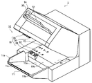
- FIG. 1 is an external view of an optical form reading apparatus according to an embodiment.
- the side view which shows schematically the internal structure of the optical form reading apparatus of FIG.
- the block diagram which shows the control system of the optical form reading apparatus of FIG. 1 functionally.
- the perspective view which shows the structure of the guide plate of FIG. FIG. 6 is a perspective view showing a guide plate and a form in FIG. 5.
- FIG. 6 is a perspective view illustrating a configuration of a guide plate according to a second embodiment.
- the perspective view which shows the time of the guide plate of FIG. 7 forming the inclined surface.
- the side view of the guide plate of FIG. The side view of the guide plate of FIG.
- FIG. The side view of the state which the guide plate of FIG. 11 lowered
- FIG. 1 is an external view of an optical form reading apparatus 1 according to an embodiment.
- FIG. 2 is a side view schematically showing the internal configuration of the optical form reading apparatus 1 of FIG.
- the optical form reading apparatus 1 includes a hopper table 11, a stacker 12, an operation panel unit 14, a conveyance path 15, a paper feed roller 16, an optical form serving as a form stacking unit.
- a reading unit 17, a guide plate 19, a control unit 20 that controls each unit in the optical form reading device 1, a power supply unit 21 that supplies electric power, and driving units for each unit (not shown) are provided.
- At least the hopper table 11, the conveyance path 15, the paper feed roller 16, and the guide plate 19 among the above-described units constitute the paper feed device 10.
- FIG. 3 is a block diagram functionally showing a control system of the optical form reading apparatus of FIG.
- FIG. 4 is an external view of the optical form reading device in FIG. 1 in an opened state.
- the control unit 20 includes a CPU 41, a memory 42, and an interface 43.
- the interface 43 is connected to the internal bus. Via the interface 43 and the internal bus, the optical reading unit 17, the display 30 as a display unit, the operation unit 31, the printing unit 50, and a drive for driving a motor, a belt, a gear, and the like for feeding and conveying a form.
- the unit 40 and various sensors are connected to the control unit 20.
- the hopper table 11 is provided so as to protrude downward from the front surface of the housing of the optical form reading device 1.
- the hopper table 11 is a form stacking unit on which a form for reading an image (form image) by the optical reading unit 17 is stacked.
- the forms stacked on the hopper table 11 are referred to as a form A, a form B,...
- the hopper table 11 has a wall surface (first reference wall surface) 11a, a wall surface 11b facing the wall surface 11a, and a table surface 11c.
- the wall surface 11a is provided vertically from one edge of the table surface 11c along the conveyance direction of the form (see FIG. 2).
- the wall surface 11a is a reference wall surface that aligns the first sides of the forms A, forms B,. That is, the wall surface 11a makes the first side A1 of the form A, the first side B1 of the form B, etc. contact the wall surface 11a in the first direction (the direction orthogonal to the transport direction in this embodiment). Composed.
- the wall surface 11b is provided vertically along the conveyance direction of the form (see FIG. 2) at the other edge of the table surface 11c. That is, the wall surface 11b is provided to face the wall surface 11a.
- Each form is sandwiched between the wall surfaces 11a and 11b and stacked on the table surface 11c.
- the table surface 11c is combined with a lifting device such as an elevator mechanism (not shown). This lifting device moves the table surface 11c to information. As a result, the uppermost form A among the plurality of forms stacked on the table surface 11 c comes into contact with the paper feed roller 16.
- This elevator mechanism has been realized in the past, and a detailed description thereof will be omitted.
- the stacker 12 is provided above the front surface of the housing of the optical form reading device 1.
- the stacker 12 stores or accommodates the forms A, forms B,..., Which are read by the optical reading unit 17 and discharged from the form discharge port 18.
- the operation panel unit 14 is provided in the vicinity of the stacker 12 above the front surface of the housing of the optical form reading apparatus 1.
- the operation panel unit 14 is used by the user for various settings.
- the operation panel unit 14 includes a display 30 and an operation unit 31.
- the display 30 displays various menus such as operation procedures, processing statuses, error contents, and the like.
- the operation unit 31 is provided with operation buttons for instructing to start and stop the processing of the form and for canceling the error.
- the conveyance path 15 is disposed adjacent to the hopper table 11 with a guide plate 19 interposed therebetween. That is, the conveyance path 15 is slightly separated from the hopper table 11.
- a plurality of transport rollers 32 are provided in the transport path 15.
- the conveyance roller 32 conveys the form A, the form B,... In which images are sequentially read by the optical reading unit 17 to the stacker 12.
- the transport rollers 32 are each composed of a pair of rollers.
- the “pair of rollers” includes a drive roller as a lower conveyance roller and a tension roller as an upper conveyance roller.
- the tension roller faces the drive roller and is urged toward the drive roller by, for example, a spring. With this configuration, the drive roller and the tension roller can hold the form A, form B,... And convey the forms in the downstream (stacker 12) direction of the conveyance path 15, respectively.
- the paper feeding roller 16 has a part of the function of the paper feeding device 10 that takes in the form A, form B,. As shown in FIGS. 2 and 4, the paper feed roller 16 is disposed between the hopper table 11 and the transport path 15 in the vicinity of the wall surface 11 a. The paper feed roller 16 takes the form A into the optical form reading device 1 from the second side A2 side of the form A, for example, and feeds the taken form A to the transport path 15. The paper feed roller 16 takes in the form B in a similar manner and feeds it to the transport path 15.
- the paper feed roller 16 includes a pickup roller 35 that sequentially takes in the forms A, B, and so on from the hopper table 11, a feed roller 36 that separates and feeds the taken forms A, B, and so on, and a reverse roller. 38.
- the pickup roller 35 is disposed on the hopper table 11.
- the lower surface of the pickup roller 35 is disposed so as to substantially coincide with a predetermined reference conveyance position.
- the pickup roller 35 comes into contact with the uppermost form A among the many forms stacked on the raised hopper table 11.
- the pickup roller 35 rotates counterclockwise (the direction in which the contacted form A is sent to the conveyance path 15) as controlled by the drive unit 40 (see FIG. 3).
- the uppermost form A in contact with the pickup roller 35 is taken into the optical form reading apparatus 1 from the form take-in port by the frictional force of the surface of the pickup roller 35.
- the drive shaft of the feed roller 36 is connected to the shaft of the pickup roller 35 by a timing belt (not shown). That is, the feed roller 36 and the pickup roller 35 rotate in the same direction. However, when the feed roller 36 includes a one-way clutch, for example, the movement of the feed roller 36 itself is different from that of the pickup roller 35.
- the reverse roller 38 is connected to a drive unit 40 (see FIG. 3) via a drive shaft and a timing belt (not shown).
- the reverse roller 38 is opposed to the feed roller 36 and is urged toward the feed roller 36 by a spring (not shown).
- the reverse roller 38 has a form separating function. As shown in FIG. 2, the reverse roller 38 rotates in the direction of the arrow (counterclockwise direction in FIG. 2) under the control of the drive unit 40. As a result, the second form B conveyed while being overlapped with the first form A is separated from the first form A by the frictional force of the surface of the reverse roller 38. Then, the form B is returned to the form taking-in port.
- the memory 42 shown in FIG. 3 stores a control program for the optical form reading apparatus 1.
- the CPU 41 controls each part of the optical form reading apparatus 1 by executing this control program.
- the CPU 41 controls the drive unit 40 to drive the pickup roller 35, the feed roller 36, the reverse roller 38, the transport roller 32, and the like. For example, when a reading start operation for the form A is performed from the operation unit 31, the CPU 41 receives the operation instruction. Next, the CPU 41 controls the motor for raising and lowering the table surface 11c of the hopper table 11 (drive unit 40) to raise the table surface 11c. Further, as the table surface 11c rises, the CPU 41 controls the drive unit 40 to rotate the pickup roller 35 in the counterclockwise direction shown in FIG.
- the optical reading unit 17 is provided on the conveyance path 15 downstream of the paper feed roller 16.
- the optical reading unit 17 is provided with two fluorescent lamps. This fluorescent lamp is for irradiating the form A with light.
- the reflected light of the light irradiated onto the form A is reflected by two mirrors as indicated by a one-dot chain line, and then guided to a contact sensor (CCD line sensor) 25.
- CCD line sensor contact sensor
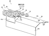
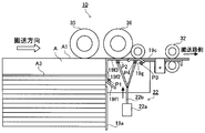
- FIG. 5 is a perspective view showing the configuration of the guide plate 19 of FIG. 6 is a perspective view showing the guide plate 19 and the form A in FIG.
- the guide plate 19 is provided between the hopper table 11 and the conveyance path 15.
- the guide plate 19 includes a wall surface (second reference wall surface) 19a, an inclined surface (inclined portion) 19b, and a horizontal surface 19c.
- the wall surface 19a is disposed in the vicinity of the hopper table 11. That is, the wall surface 19a is slightly separated from the transport path 15 (see FIG. 4).
- the wall surface 19a is provided perpendicular to the table surface 11a.
- the wall surface 19a is a reference wall surface that aligns the second side A2 and the second side B2 (see FIG. 6) of the form A, the form B,. That is, the wall surface 19a brings the second side A2 and the second side B2 into contact with the wall surface 19a in the second direction (the transport direction in this embodiment).
- the inclined surface 19b is provided at the upper end of the wall surface 19a, and is disposed on the wall surface 11b side opposite to the wall surface 11a side between the hopper table 11 and the transport path 15. The inclined surface 19b is inclined from the wall surface 19a toward the conveyance path 15.
- the horizontal surface 19c is provided at the upper end of the inclined surface 19b.
- the horizontal surface 19c extends substantially horizontally along the transport direction to the transport path 15 side.
- a plurality of transport rollers 32 are coaxially arranged on the horizontal surface 19c.
- the transport roller 32 can transport the form A to the transport path 15.
- the guide plate 19 has a convex portion 19d disposed on the wall surface 11a side between the wall surface 19a and the horizontal surface 19c.
- the convex portion 19d has a bottom surface formed of a substantially right triangular triangular prism shape.
- an inclined surface 19b is disposed with a step 19e. That is, the bottom surface forms a step 19e. Accordingly, the step 19e has a substantially right triangle shape.
- a paper feed roller 16 (feed roller 36, pickup roller 35, reverse roller 38) is disposed on the convex portion 19d, so that the forms A, forms B,... Can be picked up.
- the forms A, forms B,... Stacked on the hopper table 11 are stacked as shown in FIG.
- the position of the side A1 of the form A arranged on the side of the reference wall surface 11a adjacent to the paper feed roller 16 from the table surface 11c is the table surface 11c of the side A3 of the form A opposite to the side A1. It is assumed that it is higher than the position from.
- the plurality of forms A, forms B,... Stacked on the hopper table 11 do not all have the same width. That is, a form having a large width and a form having a small width are mixed.
- control unit 20 controls the drive unit 40 to rotate the pickup roller 35 in the direction of the arrow (see FIG. 6). Or the hopper table 11 is raised.
- the uppermost form A among the forms loaded on the hopper table 11 comes into contact with the pickup roller 35 at a reference transport position at an optimum height for picking up.
- the control is performed.
- the unit 20 stops the hopper table 11 from rising.
- the uppermost form A is drawn into the transport path 15 by the rotating pickup roller 35.
- the control unit 20 controls the driving unit 40 to rotate the feed roller 36 forward (counterclockwise rotation in FIG. 2) and reversely rotate the reverse roller 38 (counterclockwise rotation in FIG. 2).
- the form A fed out by the pickup roller 35 is taken into the transport path 15 by the rotation of each roller.
- Form B ... is also taken in the same way as form A.
- the position of the side A3 of the form A drawn into the optical form reading apparatus 1 from the table surface 11c is lower than the position of the side A1 of the form A from the table surface 11c. . That is, the side A3 side of the form A is positioned lower than the reference transport position optimum for the pickup of the form A.
- the guide plate 19 can be overcome. In other words, the form A is taken into the conveyance path 15 side at the height of the reference conveyance position with the side A2 getting over the inclined surface 19b of the guide plate 19. Then, the form A is conveyed to the reading position of the optical reading unit 17 by the conveying roller 32 (see FIG. 2).
- Form B ... is also conveyed in the same manner as form A.
- the rotation speeds of the plurality of drive rollers are made the same by the pulse motor so that the images do not expand and contract.
- Image signals of the images of form A, form B,... Read by the contact sensor of the optical reading unit 17 are output to the control unit 20.
- the CPU 41 generates images of the front surfaces of the forms A, forms B,... From the input image signal, and performs post-processing on the generated images. Examples of post-processing include character recognition processing.
- the forms A, forms B,... Subjected to surface reading processing by the optical reading unit 17 and the control unit 20 in this way are sequentially conveyed on the conveyance path 15 to the form discharge port 18 side. As a result, the form A, the form B,... Are sequentially accumulated (stored or accommodated) in the stacker 12.
- the guide plate 19 is disposed between the hopper table 11 and the conveyance path 15.
- the guide plate 19 has an inclined surface 19 b inclined from the second reference wall surface 19 a on the hopper table 11 side toward the conveyance path 15.
- the side A3 side of the form A can easily get over the inclined surface 19b.
- the side B3 of the form B can easily get over the inclined surface 19b.
- the inclined surface 19b of the guide plate 19 is disposed on the wall surface 11b side opposite to the wall surface 11a side between the hopper table 11 and the transport path 15. . Therefore, even if the position of the side A3 of the form A to be taken in from the table surface 11c is lower than the position of the side A1 of the form A on the wall surface 11a side from the table surface 11c, the form A has the inclined surface 19b. You can get over. Therefore, in the optical form reading apparatus 1 of the present embodiment, it is possible to take in a stable form without causing a conveyance failure.
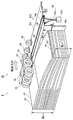
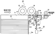
- FIG. 7 is a perspective view illustrating a configuration of the guide plate 219 according to the second embodiment.
- FIG. 8 is a perspective view showing the time when the guide plate 219 of FIG. 7 forms the inclined surface 219b.
- FIG. 9 is a side view of the guide plate 219 of FIG.
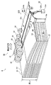
- FIG. 10 is a side view of the guide plate 219 of FIG. 7 to 10, the same components as those in the first embodiment shown in FIGS. 1 to 6 are given the same reference numerals, and the description thereof is omitted. As shown in FIGS.
- the optical form reading device 2 of Embodiment 2 includes a guide plate 219 instead of the guide plate 19 provided in the optical form reading device 2 of Embodiment 1, A movable portion 22 is provided.
- the guide plate 219 includes first and second plate members 19f and 19g that are movable so as to form an inclined surface 219b corresponding to the inclined surface 19b of the first embodiment.
- the first plate member 19f is connected to the first plate member 19f in order, and the first to third plate members 19f1, 19f2, 19f3 each having a substantially U-shaped cross section as a whole. It is composed of The first plate member 19f is formed so that the inner angle formed by the first plate material 19f1 and the second plate material 19f2 is approximately 125 degrees. The internal angle formed by the connecting portion between the second plate material 19f2 and the third plate material 19f3 is 90 degrees.
- the first plate member 19f is configured to be rotatable in the arrow direction (see FIG. 10) with a connection portion P1 of the side 19f4 formed by the second plate material 19f2 and the third plate material 19f3 as a fulcrum. .
- a mounting portion P2 is formed on the lower surface of the third plate member 19f3.
- One end of a bifurcated drive shaft 22b, which will be described later, is connected to the mounting portion P2.
- the attachment part P2 functions as an action point for the connection part P1.
- the second plate member 19g is formed in a substantially flat plate shape.
- the second plate member 19g is configured to be rotatable in the arrow direction (see FIG. 10) with the connecting portion P3 on one side of the conveyance path 15 as a fulcrum.
- a mounting portion P4 is formed on the lower surface of the second plate member 19g.
- the other end of the bifurcated drive shaft 22b, which will be described later, is connected to the mounting portion P4.
- the attachment part P4 functions as an action point for the connection part P3.
- the first plate member 19f rotates counterclockwise in FIG. 10 with the connection portion P1 as a fulcrum
- the second plate member 19g rotates in the clockwise direction in FIG. 10 with the connection portion P3 as a fulcrum.
- the second plate member 19f2 of the first plate member 19f moves vertically on the wall surface 19a.
- the third plate member 19f3 of the first plate member 19f moves horizontally at the same height as the horizontal surface 19c.
- the second plate member 19g also moves horizontally at the same height as the horizontal surface 19c, and the side 19f5 of the third plate member 19f3 and the side 19g1 of the second plate member 19g on the hopper table 11 side. Close and oppose. Accordingly, the second plate member 19f2 can form a wall surface similar to the wall surface 19a, and the third plate member 19f3 and the second plate member 19g can form a horizontal surface similar to the horizontal surface 19c.
- the first plate member 19f rotates 45 degrees clockwise with the connecting portion P1 as the fulcrum
- the second plate member 19g has the connecting portion P3 as the fulcrum, as shown in FIG. Turn 45 degrees clockwise.
- the second plate member 19 f 2 of the first plate member 19 f is inclined from the hopper table 11 toward the conveyance path 15.
- the second plate member 19 g is also inclined from the hopper table 11 toward the conveyance path 15. Then, the side 19f4 formed by the second plate material 19f2 and the third plate material 19f3 and the side 19g1 of the second plate member 19g approach each other and face each other. Thereby, the 2nd board
- the movable part 22 moves the first plate member 19f and the second plate member 19g.
- the movable part 22 has a motor 22a and a drive shaft 22b.
- the motor 22a moves the drive shaft 22b in the vertical direction by rotation control by the control unit 20.
- the upper end side of the drive shaft 22b is bifurcated.
- An attachment portion P2 of the third plate member 19f3 is rotatably connected to one end of the bifurcated portion.
- an attachment portion P4 of the second plate member 19g is rotatably connected to the other end of the fork.
- the optical form reading apparatus 2 when an instruction command for starting processing (reading a form) is input from the operation unit 31, the control unit 20 controls the rotation of the motor 22a to lower the drive shaft 22b.
- the first plate member 19f rotates 45 degrees clockwise around the connection portion P1.
- the second plate material 19f2 of the first plate member 19f is inclined 45 degrees from the hopper table 11 toward the transport path 15.
- the second plate member 19g rotates 45 degrees counterclockwise with the connection portion P3 as a fulcrum.
- the second plate member 19 g is inclined 45 degrees from the hopper table 11 toward the conveyance path 15.
- the side 19f4 formed by the second plate material 19f2 and the third plate material 19f3 and the side 19g1 of the second plate member 19g are close to each other and face each other.
- the second plate member 19f2 and the second plate member 19g form an inclined surface 219b that continues at the same inclination.
- the control unit 20 rotates the pickup roller 35 in the arrow direction (see FIG. 10).
- the control unit 20 controls the drive unit 40 to raise the hopper table 11.
- the control unit 20 stops the ascent of the hopper table 11.
- the uppermost form A is drawn into the transport path 15 by the rotating pickup roller 35.
- the control unit 20 controls the drive unit 40 to rotate the feed roller 36 forward (counterclockwise in FIG. 2) and reversely rotate the reverse roller 38 (counterclockwise in FIG. 2). Rotate around).
- the form A fed out by the pickup roller 35 gets over the inclined surface 219b formed by the second plate member 19f2 and the second plate member 19g and is taken into the conveyance path 15.
- the form B is taken into the transport path 15.
- the taking-in operation of the forms A, forms B,... is repeated until a command for instructing stoppage is input or the forms A, forms B,.
- the position of the side A3 of the form A drawn into the optical form reading device 2 from the table surface 11c is lower than the position of the side A1 of the form A from the table surface 11c. That is, the side A3 side of the form A is positioned lower than the reference transport position optimum for the pickup of the form A.
- the side A3 of the form A is guided on the inclined surface 219b of the guide plate 219 and can get over the guide plate 219.
- the form A is taken into the transport path 15 side at the height of the reference transport position, with the side A2 getting over the inclined surface 219b of the guide plate 219.
- the form A is conveyed to the reading position of the optical reading unit 17 by the conveying roller 32 (see FIG. 2).
- Form B ... is also conveyed in the same manner as form A.
- control unit 20 stops pickup roller 35.
- the control unit 20 controls the drive unit 40 to lower the hopper table 11.
- control unit 20 stops the feed roller 36, the reverse roller 38, and the transport roller 32. Next, the control unit 20 controls the rotation of the motor 22a to raise the drive shaft 22b.
- the first plate member 19f rotates 45 degrees counterclockwise with the connecting portion P1 as a fulcrum.
- the second plate member 19g rotates 45 degrees clockwise with the connecting portion P3 as a fulcrum.
- the second plate member 19g also moves horizontally at the same height as the horizontal surface 19c, and the side 19f5 of the third plate member 19f3 and the side 19g1 of the second plate member 19g on the hopper table 11 side. Close and oppose.
- the second plate member 19f2 forms a wall surface similar to the wall surface 19a
- the third plate member 19f3 and the second plate member 19g form a horizontal surface having the same height as the horizontal surface 19c, and the operation ends. To do.
- the optical form reading apparatus 2 of this embodiment includes the first and second plate members 19f and 19g in which the guide plate 219 is movable.
- the inclined surface 219b of the guide plate 219 inclined from the second reference wall surface 19a on the hopper table 11 side toward the transport path 15 is formed by the first and second plate members 19f and 19g.
- the form A, the form B,... Can get over the inclined surface 219b, and a stable form can be taken in without causing a conveyance failure.
- the first and second plate members 19f and 19g form the inclined surface 219b of the guide plate 219 when a command for starting processing is input. Further, in the optical form reading apparatus 2, the first and second plate members 19f and 19g do not form the inclined surface 219b of the guide plate 219 except when a command for starting processing is input. Therefore, the optical form reading device 2 enables accurate form taking in as necessary.
- first and second plate members 19f and 19g are configured to be moved by the movable portion 22.
- the present invention is not limited to this.
- an operator may manually move the first and second plate members 19f and 19g.
- the first plate member 19f is formed in a substantially U shape having a cross section as a whole, but the present invention is not limited thereto.
- the first plate material 19f1 may not be provided. That is, it is also possible to form the first plate member 19f having an L-shaped cross section made of the second and third plate materials 19f2 and 19f3. In this case, the first plate member 19f is rotated using the connection point P1 on one side in the longitudinal direction of the second plate material 19f2 as a fulcrum.
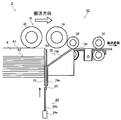
- FIG. 11 is a side view of the guide plate 19 according to the third embodiment.
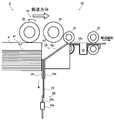
- FIG. 12 is a side view of the guide plate 19 of FIG. 11 with the partition plate 23 lowered.
- the same components as those in the first and second embodiments shown in FIGS. 1 to 10 are denoted by the same reference numerals, and the description thereof is omitted.
- the optical form reading apparatus 3 according to the third embodiment includes a partition plate 23 and a moving unit 24 that is a partition plate moving unit.
- the partition plate 23 is disposed between the hopper table 11 and the guide plate 19.
- the partition plate 23 is movably provided by driving the moving unit 24. As the partition plate 23 moves, the hopper table 11 and the guide plate 19 are partitioned or the partition is released. That is, the partition plate 23 is held so as to be movable in the vertical direction between the holding member 25 on the hopper table 11 side and the wall surface 19 a of the guide plate 19.
- the lower end of the partition plate 23 is connected to the tip of a moving shaft 24b of the moving unit 24 described later.
- the moving unit 24 includes a motor 24a and a moving shaft 24b.
- the motor 24 a moves the moving shaft 24 b up and down in the direction of the paper feed roller 6 or away from the paper feed roller 6 by the rotation control of the control unit 20.
- the moving shaft 24 b has an upper end connected to the lower end of the partition plate 23.
- the optical form reading device 3 is in the state described in FIG. 11 as an initial state. That is, the state in which the partition plate 23 partitions the hopper table 11 and the guide plate 19 is an initial state.
- the control unit 20 controls the rotation of the motor 24a to lower the moving shaft 24b.
- the partition plate 23 slides between the holding member 25 and the wall surface 19a of the guide plate 19 and descends in the direction of the arrow (in the direction away from the paper feed roller 6). To do. As a result, the hopper table 11 and the guide plate 19 are not partitioned by the partition plate 23 (partition release).
- the control unit 20 controls the drive unit 40 to rotate the pickup roller 35 in the arrow direction (see FIG. 12) or raise the hopper table 11.
- the control unit 20 stops the hopper table 11 from being raised.
- the control unit 20 controls the drive unit 40 to rotate the feed roller 36 forward (rotation in the counterclockwise direction in FIG. 2) and reversely rotate the reverse roller 38 (reverse in FIG. 2). Rotate clockwise).
- the form A fed out by the pickup roller 35 gets over the inclined surface 19b of the guide plate 19 and is taken into the transport path 15.
- the operation for taking in the form A is repeated until a command for instructing stoppage is input or until the form disappears from the hopper table 11.
- the form A is guided on the inclined surface 19b of the guide plate 19 and can get over the guide plate 19.
- the side A2 of the form A gets over the inclined surface 19b of the guide plate 19 and is taken into the conveyance path 15 side.
- the form A is conveyed to the reading position of the optical reading unit 17 by the conveying roller 32 (see FIG. 2).
- Form B... Is also taken in the same manner as form A and conveyed to the reading position of the optical reading unit 17.
- control unit 20 controls the drive unit 40 to stop the pickup roller 35 or lower the hopper table 11. I will let you.
- control unit 20 stops the feed roller 36, the reverse roller 38, and the transport roller 32. Next, the control unit 20 controls the rotation of the motor 24a to raise the moving shaft 24b.
- the sheet feeding device 10 includes the partition plate 23 that partitions the hopper table 11 and the guide plate 19.
- the partition plate 23 is lowered.
- the hopper table 11 and the guide plate 19 are not partitioned by the partition plate 23.
- the form A, the form B,... Can get over the inclined surface 19b, and it is possible to take in a stable form without causing a conveyance failure.
- the partition plate 23 is lowered when there is a command input for processing start.
- the hopper table 11 and the guide plate 19 are not partitioned by the partition plate 23. That is, the partition between the hopper table 11 and the guide plate 19 by the partition plate 23 is released when the form A, the form B,.
- the hopper table 11 and the guide plate 19 are partitioned by the partition plate 23.
- A, B Form, A1, A2, A3, B1, B2, B3 ... Form sides, P1, P3 ... Connection part, P2, P4 ... Mounting part, 1 ...
- Optical form reading device 10 ... Paper feeding device, DESCRIPTION OF SYMBOLS 11 ... Hopper table, 11a, 11b ... Wall surface, 11c ... Table surface, 12 ... Stacker, 14 ... Operation panel part, 15 ... Conveyance path, 16 ... Paper feed roller, 17 ... Optical reading part, 18 ... Form discharge port, 19 , 219 ... guide plate, 19a ... wall surface, 19b, 219b ... inclined surface, 19c ... horizontal surface, 19d ... convex part, 19e ...
- step 19f ... first plate member, 19f1 ... first plate member, 19f2 ... second Plate material, 19f3 ... third plate material, 19f4, 19f5, 19g1 ... side, 19g ... second plate member, 20 ... control section, 21 ... power supply section, 22 ... movable section, 22a ... motor, 22b ... drive shaft, 23 ... partition plate, 24 ... moving part, 24 DESCRIPTION OF SYMBOLS ... Motor, 24b ... Moving shaft, 25 ... Contact sensor, 30 ... Display, 31 ... Operation part, 32 ... Conveyance roller, 33 ... Drive roller, 35 ... Pickup roller, 36 ... Feed roller, 38 ... Reverse roller, 40 ... Drive , 42... Memory, 43... Interface, printing unit 50.
Landscapes
- Engineering & Computer Science (AREA)
- Mechanical Engineering (AREA)
- Sheets, Magazines, And Separation Thereof (AREA)
- Facsimile Scanning Arrangements (AREA)
Abstract
L'invention porte sur un dispositif d'alimentation en papier (10), lequel dispositif comprend : une table de trémie (11), qui supporte des documents (A, B) ; une première surface de paroi de référence (11a) pour aligner un premier côté (A1, B1) du document (A, B) sur la table de trémie ; une seconde surface de paroi de référence (19a) pour aligner un second côté (A2, B2) du document (A, B) sur la table de trémie (11) ; des rouleaux d'avance de papier (16), qui fournissent le document (A, B) sur la table de trémie (11) vers la trajectoire de transport (15) ; et une plaque de guidage (19), qui a une surface inclinée (19b) et une section saillante (19d). La surface inclinée (19b) et la section saillante (19d) sont disposées entre la table de trémie (11) et la trajectoire de transport (15). La section saillante (19d) est disposée sur le côté de la première surface de paroi de référence (11a). Les rouleaux d'avance de papier (16) sont disposés sur la section saillante (19d).
Priority Applications (1)
| Application Number | Priority Date | Filing Date | Title |
|---|---|---|---|
| CN201380000027.4A CN103547521A (zh) | 2012-03-26 | 2013-02-04 | 供纸装置 |
Applications Claiming Priority (2)
| Application Number | Priority Date | Filing Date | Title |
|---|---|---|---|
| JP2012069403A JP2013199360A (ja) | 2012-03-26 | 2012-03-26 | 給紙装置 |
| JP2012-069403 | 2012-03-26 |
Publications (1)
| Publication Number | Publication Date |
|---|---|
| WO2013145524A1 true WO2013145524A1 (fr) | 2013-10-03 |
Family
ID=49258851
Family Applications (1)
| Application Number | Title | Priority Date | Filing Date |
|---|---|---|---|
| PCT/JP2013/000604 Ceased WO2013145524A1 (fr) | 2012-03-26 | 2013-02-04 | Dispositif d'alimentation en papier |
Country Status (3)
| Country | Link |
|---|---|
| JP (1) | JP2013199360A (fr) |
| CN (1) | CN103547521A (fr) |
| WO (1) | WO2013145524A1 (fr) |
Citations (4)
| Publication number | Priority date | Publication date | Assignee | Title |
|---|---|---|---|---|
| JPS5628143A (en) * | 1979-08-15 | 1981-03-19 | Hitachi Ltd | Form feeding apparatus for optical reader |
| JPS5635283A (en) * | 1979-08-31 | 1981-04-07 | Hitachi Ltd | Slip feeding device for optical reader |
| JPS64548U (fr) * | 1987-06-18 | 1989-01-05 | ||
| JPH0930668A (ja) * | 1995-07-17 | 1997-02-04 | Nec Eng Ltd | 自動給紙機構 |
Family Cites Families (1)
| Publication number | Priority date | Publication date | Assignee | Title |
|---|---|---|---|---|
| JP5047898B2 (ja) * | 2007-08-31 | 2012-10-10 | 株式会社東芝 | 画像形成装置 |
-
2012
- 2012-03-26 JP JP2012069403A patent/JP2013199360A/ja active Pending
-
2013
- 2013-02-04 CN CN201380000027.4A patent/CN103547521A/zh active Pending
- 2013-02-04 WO PCT/JP2013/000604 patent/WO2013145524A1/fr not_active Ceased
Patent Citations (4)
| Publication number | Priority date | Publication date | Assignee | Title |
|---|---|---|---|---|
| JPS5628143A (en) * | 1979-08-15 | 1981-03-19 | Hitachi Ltd | Form feeding apparatus for optical reader |
| JPS5635283A (en) * | 1979-08-31 | 1981-04-07 | Hitachi Ltd | Slip feeding device for optical reader |
| JPS64548U (fr) * | 1987-06-18 | 1989-01-05 | ||
| JPH0930668A (ja) * | 1995-07-17 | 1997-02-04 | Nec Eng Ltd | 自動給紙機構 |
Also Published As
| Publication number | Publication date |
|---|---|
| CN103547521A (zh) | 2014-01-29 |
| JP2013199360A (ja) | 2013-10-03 |
Similar Documents
| Publication | Publication Date | Title |
|---|---|---|
| JP7559899B2 (ja) | 媒体給送装置及び画像読取装置 | |
| CN109319538B (zh) | 图像读取装置 | |
| JP6926719B2 (ja) | 画像読取装置 | |
| TW201934462A (zh) | 媒體搬送裝置及圖像讀取裝置 | |
| JP2020083615A (ja) | 媒体搬送装置、画像読取装置、搬送制御方法 | |
| CN110872020A (zh) | 输送装置和图像检查装置 | |
| CN105388720A (zh) | 手动供给装置以及包括该手动供给装置的图像形成装置 | |
| US7533882B2 (en) | Automatic document feeder | |
| US9641717B2 (en) | Image scanning apparatus and image forming apparatus with repositioning auxiliary medium guide for mixed document widths | |
| JP4871974B2 (ja) | シート給紙装置 | |
| JP7786182B2 (ja) | 原稿搬送装置 | |
| CN112573275B (zh) | 排纸装置、排纸装置的控制方法、处理装置以及记录系统 | |
| JP4693176B2 (ja) | シート給送装置、該装置を備えた画像読取装置及び画像形成装置 | |
| JP2013199360A (ja) | 給紙装置 | |
| JP2018043854A (ja) | シート給送装置、画像読取装置、画像形成装置及び綴じられたシートの検出方法 | |
| WO2016121146A1 (fr) | Machine de comptage de papier-monnaie | |
| CN108369654B (zh) | 卡送出装置 | |
| JP6435876B2 (ja) | 給紙装置 | |
| JP6514627B2 (ja) | 読取装置及び複合装置 | |
| CN114655748B (zh) | 介质进给装置、图像读取装置、介质进给方法 | |
| JP7720712B2 (ja) | 媒体搬送装置、制御方法及び制御プログラム | |
| JP2015128243A (ja) | 画像読取装置 | |
| JP7601669B2 (ja) | 媒体搬送装置、制御方法及び制御プログラム | |
| JP2018074399A (ja) | 媒体搬送装置および画像読取装置 | |
| JP2010208800A (ja) | 給紙装置 |
Legal Events
| Date | Code | Title | Description |
|---|---|---|---|
| 121 | Ep: the epo has been informed by wipo that ep was designated in this application |
Ref document number: 13768184 Country of ref document: EP Kind code of ref document: A1 |
|
| NENP | Non-entry into the national phase |
Ref country code: DE |
|
| 122 | Ep: pct application non-entry in european phase |
Ref document number: 13768184 Country of ref document: EP Kind code of ref document: A1 |