WO2013146127A1 - Enrouleur - Google Patents
Enrouleur Download PDFInfo
- Publication number
- WO2013146127A1 WO2013146127A1 PCT/JP2013/056028 JP2013056028W WO2013146127A1 WO 2013146127 A1 WO2013146127 A1 WO 2013146127A1 JP 2013056028 W JP2013056028 W JP 2013056028W WO 2013146127 A1 WO2013146127 A1 WO 2013146127A1
- Authority
- WO
- WIPO (PCT)
- Prior art keywords
- main body
- peripheral wall
- winding
- reel
- wall portion
- Prior art date
- Legal status (The legal status is an assumption and is not a legal conclusion. Google has not performed a legal analysis and makes no representation as to the accuracy of the status listed.)
- Ceased
Links
Images


Classifications
-
- B—PERFORMING OPERATIONS; TRANSPORTING
- B65—CONVEYING; PACKING; STORING; HANDLING THIN OR FILAMENTARY MATERIAL
- B65H—HANDLING THIN OR FILAMENTARY MATERIAL, e.g. SHEETS, WEBS, CABLES
- B65H75/00—Storing webs, tapes, or filamentary material, e.g. on reels
- B65H75/02—Cores, formers, supports, or holders for coiled, wound, or folded material, e.g. reels, spindles, bobbins, cop tubes, cans, mandrels or chucks
-
- G—PHYSICS
- G11—INFORMATION STORAGE
- G11B—INFORMATION STORAGE BASED ON RELATIVE MOVEMENT BETWEEN RECORD CARRIER AND TRANSDUCER
- G11B23/00—Record carriers not specific to the method of recording or reproducing; Accessories, e.g. containers, specially adapted for co-operation with the recording or reproducing apparatus ; Intermediate mediums; Apparatus or processes specially adapted for their manufacture
- G11B23/02—Containers; Storing means both adapted to cooperate with the recording or reproducing means
- G11B23/04—Magazines; Cassettes for webs or filaments
- G11B23/041—Details
- G11B23/044—Reels or cores; positioning of the reels in the cassette
-
- G—PHYSICS
- G11—INFORMATION STORAGE
- G11B—INFORMATION STORAGE BASED ON RELATIVE MOVEMENT BETWEEN RECORD CARRIER AND TRANSDUCER
- G11B23/00—Record carriers not specific to the method of recording or reproducing; Accessories, e.g. containers, specially adapted for co-operation with the recording or reproducing apparatus ; Intermediate mediums; Apparatus or processes specially adapted for their manufacture
- G11B23/02—Containers; Storing means both adapted to cooperate with the recording or reproducing means
- G11B23/037—Single reels or spools
-
- G—PHYSICS
- G11—INFORMATION STORAGE
- G11B—INFORMATION STORAGE BASED ON RELATIVE MOVEMENT BETWEEN RECORD CARRIER AND TRANSDUCER
- G11B23/00—Record carriers not specific to the method of recording or reproducing; Accessories, e.g. containers, specially adapted for co-operation with the recording or reproducing apparatus ; Intermediate mediums; Apparatus or processes specially adapted for their manufacture
- G11B23/02—Containers; Storing means both adapted to cooperate with the recording or reproducing means
- G11B23/113—Apparatus or processes specially adapted for the manufacture of magazines or cassettes, e.g. initial loading into container
Definitions
- the present invention relates to a reel on which a recording tape such as a magnetic tape is wound.
- a reel hub including a pair of upper flange plate and lower flange plate and a reel hub formed integrally with the lower flange plate is known (see, for example, JP-A-10-199195).
- a reel hub disclosed in Japanese Patent Application Laid-Open No. 10-199195 includes a central part in which a hub hole into which a rotating shaft is inserted is formed, a cylindrical winding part around which a magnetic tape is wound, a central part and a winding part. And reinforcing ribs that connect the parts.
- the lower flange plate disclosed in Japanese Patent Laid-Open No. 10-199195 is formed with an annular deformation absorbing groove along the outer peripheral surface of the winding portion.
- this deformation absorbing groove By this deformation absorbing groove, the deformation of the lower flange plate is suppressed by absorbing the elastic deformation of the wound portion that tilts toward the center due to the winding pressure of the magnetic tape.
- the present invention has been made in consideration of the above facts, and an object of the present invention is to obtain a reel capable of suppressing the relative position between the lid portion of the hub main body portion and the winding portion from shifting in the axial direction of the winding portion.
- a reel according to a first aspect of the present invention is formed in a cylindrical shape, a hub main body portion having a cylindrical main body peripheral wall portion and a lid portion provided on one end side in the axial direction of the main peripheral wall portion.
- the reel according to the first aspect when the outer peripheral surface of the winding part is pressed toward the main body peripheral wall part side of the hub main body part by the winding pressure of the recording tape of a predetermined value or more, it is formed in the connecting part.
- the deformation absorbing portion is elastically deformed, and the winding portion is displaced toward the main body peripheral wall portion.
- transformation to the radial inside of a main body surrounding wall part is suppressed
- transformation of the cover part of a hub main-body part is suppressed.
- the relative position between the lid portion and the winding portion is suppressed from shifting in the axial direction of the winding portion. Therefore, the running position change of the recording tape is suppressed, and the winding deviation of the recording tape with respect to the outer peripheral surface of the winding portion is suppressed.
- a reel according to a second aspect of the present invention is the reel according to the first aspect, wherein the connecting portion is located at a position shifted in the axial direction of the main body peripheral wall portion with respect to the lid portion. It is connected.
- the connecting portion is connected to the main body peripheral wall portion at a position shifted in the axial direction of the main body peripheral wall portion with respect to the lid portion. Therefore, the winding pressure of the recording tape is input to the main body peripheral wall portion via the connecting portion at a position shifted in the axial direction of the main body peripheral wall portion with respect to the lid portion.
- the main body peripheral wall portion is likely to be deformed. It becomes easy.
- the present invention is particularly effective for such a configuration in which the lid portion is easily deformed.
- a reel according to a third aspect of the present invention is the reel according to the first aspect or the second aspect, wherein the connecting portion is an outer tension projecting radially inward from the inner peripheral surface of the winding portion.
- a projecting portion, and an inner projecting portion projecting radially outward from an outer peripheral surface of the main body peripheral wall portion, and the deformation absorbing portion places the inner projecting portion with respect to the outer projecting portion. It is a level
- the step part formed in the connecting part is elastic.
- the said winding part displaces to the main body surrounding wall part side.
- transformation to the radial inside of a main body surrounding wall part is suppressed, a deformation
- the relative position between the lid portion and the winding portion is suppressed from shifting in the axial direction of the winding portion.
- the reel according to a fourth aspect of the present invention is the reel according to the third aspect, wherein the stepped portion is located on the opening side of the main body peripheral wall portion with respect to the outer overhang portion.
- the inner projecting portion of the connecting portion is located on the opening side of the peripheral wall portion with respect to the outer projecting portion by the step portion.
- the main body peripheral wall portion has a moment that tilts the main body peripheral wall portion inward in the radial direction with the connection portion with the lid portion as a fulcrum.
- inner moment a moment that tilts the main body peripheral wall portion inward in the radial direction with the connection portion with the lid portion as a fulcrum.
- the side of the winding portion a moment that tilts the main body peripheral wall portion inward in the radial direction with the connection portion with the lid portion as a fulcrum.
- the inner overhanging portion protrudes radially outward from the opening-side end portion of the peripheral wall portion of the main body.
- the inner projecting portion projects outward in the radial direction from the opening-side end portion of the peripheral wall portion of the main body. Therefore, compared with the configuration in which the inner overhanging portion projects radially outward from the position where the inner overhanging portion is shifted from the opening side end portion of the main body peripheral wall portion to the lid side, the step portion is made thin in the axial direction of the entire reel.
- the axial length of the peripheral wall portion of the main body can be increased.
- the stepped portion is easily elastically deformed toward the main body peripheral wall portion with the connecting portion with the inner overhanging portion as a fulcrum, so that deformation of the main body peripheral wall portion in the radial direction is further suppressed.
- the stepped portion positions the inner overhanging portion on the lid portion side with respect to the outer overhanging portion.
- the inner projecting portion of the connecting portion is positioned on the lid portion side of the hub main body portion with respect to the outer projecting portion by the stepped portion, so that the opening side of the peripheral wall portion of the main body
- the configuration of is simplified.
- a reel according to a seventh aspect of the present invention is the reel according to the first aspect or the second aspect, wherein the connecting portion is an outer tension projecting radially inward from the inner peripheral surface of the winding portion.
- a projecting portion and an inner projecting portion projecting radially outward from the outer peripheral surface of the main body peripheral wall portion, and the deformation absorbing portion is interposed between the winding portion and the main body peripheral wall portion.
- An axial direction of the portion is disposed as a longitudinal direction, one end in the longitudinal direction is connected to the winding portion via the outer overhanging portion, and the other end in the longitudinal direction is connected to the peripheral wall portion of the main body via the inner overhanging portion. It is the connected wall-like part.
- the wall-shaped portion formed in the connecting portion is By elastically deforming, the winding part is displaced toward the main body peripheral wall part.
- a reel according to an eighth aspect of the present invention is the reel according to any one of the third to seventh aspects, wherein the outer overhanging portion extends from an axially central portion of the winding portion. Projects radially inward.
- the outer projecting portion of the connecting portion projects radially inward from the axial central portion of the winding portion. That is, the axial center part of the winding part is supported by the main body peripheral wall part via the connecting part.
- the reel according to a ninth aspect of the present invention is the reel according to any one of the third to eighth aspects, wherein the stepped portion is annular along the outer peripheral surface of the main body peripheral wall portion. It extends.
- the step portion extends in an annular shape along the outer peripheral surface of the main body peripheral wall portion, the deformation of the main body peripheral wall portion toward the radially inner side is suppressed over the entire circumference of the main body peripheral wall portion. Is done.
- a reel according to a tenth aspect of the present invention is the reel according to any one of the first aspect to the ninth aspect, wherein the hub main body portion houses the hub main body portion in the lid portion.
- a positioning portion for positioning with respect to the casing to be formed is formed.
- the positioning part for positioning the hub main body part with respect to the housing is formed on the lid part. Accordingly, by suppressing the deformation of the lid portion, the positional deviation of the hub body portion with respect to the housing is suppressed.
- a reel according to an eleventh aspect of the present invention is the reel according to any one of the first aspect to the tenth aspect described above, wherein the hub main body portion is rotationally driven inside the main body peripheral wall portion.
- a housing portion for housing the motor is formed.
- the reel of the present invention it is possible to suppress the relative position between the lid portion of the hub main body portion and the winding portion from shifting in the axial direction of the winding portion.
- FIG. 1 is a perspective view showing a state in which a reel according to the first embodiment of the present invention is incorporated in a drive device.
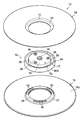
- FIG. 2 is an exploded perspective view showing the reel shown in FIG.
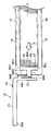
- FIG. 3 is a perspective view showing a longitudinal section along the axial direction of the reel shown in FIG.
- FIG. 4 is a plan view of the reel shown in FIG. 1 as viewed from the upper flange side.
- 5 is a cross-sectional view corresponding to the cross-sectional view taken along line 5-5 of FIG.
- FIG. 6 is a cross-sectional view corresponding to FIG. 5 showing the connecting portion in the second embodiment of the present invention.
- FIG. 7 is a cross-sectional view corresponding to FIG. 5 showing the connecting portion in the third embodiment of the present invention.
- FIG. 1 is a perspective view showing a state in which a reel according to the first embodiment of the present invention is incorporated in a drive device.
- FIG. 2 is an exploded perspective view showing the reel shown in
- FIG. 8 is a cross-sectional view corresponding to FIG. 5 and showing a coupling portion between the upper flange and the lower flange in the fourth embodiment of the present invention.
- FIG. 9A is a cross-sectional view corresponding to a partially enlarged view of FIG. 3 showing an analytical model of a reel according to the embodiment.
- FIG. 9B is a cross-sectional view corresponding to a partially enlarged view of FIG. 3 illustrating the reel analysis model according to the embodiment.
- FIG. 10 is a cross-sectional view corresponding to a partially enlarged view of FIG. 3 showing an analytical model of a reel according to a comparative example.
- FIG. 11 is a graph illustrating the analysis results of each analysis model according to the example and the comparative example.
- the arrow UP in FIG. 1 is the upward direction
- the arrow DO is the downward direction
- the rotation axis direction of the reels 10 and 20 according to this embodiment is the vertical direction (height direction).
- the pair of reels 10 and 20 according to the first embodiment are made of a synthetic resin such as polycarbonate (PC), for example, and as shown in FIG. 1, the casing 52 (the bottom plate 54 in FIG. 1) of the drive device 50 is used. And only three struts 56 are shown).
- PC polycarbonate
- the reel 10 is used for feeding out the recording tape T.
- the reel 20 is used for winding the recording tape T.
- the recording tape T fed from the reel 10 is slidably contacted with the recording / reproducing head 60 while being wound around the reel 20.
- the recording / reproducing head 60 records data on the recording tape T and reads data recorded on the recording tape T.
- a plurality of tape guides 58 are rotatably provided on the bottom plate 54 on both sides of the recording / reproducing head 60.
- the recording tape T drawn out from the reel 10 and taken up on the reel 20 is guided by each tape guide 58.
- Each of the reels 10 and 20 includes reel hubs 12 and 22 constituting an axial center portion, annular upper flanges 14 and 24 provided on the upper end side thereof, and annular lower flanges 16 and 26 provided on the lower end side thereof. It is comprised including.
- a recording tape T such as a magnetic tape as an information recording / reproducing medium is wound around the outer peripheral surface of the reel hub 12 in the reel 10.
- the recording tape T wound around the outer peripheral surface of the reel hub 12 is fed out toward the reel 20 while being guided by the upper flange 14 and the lower flange 16.
- the recording tape T fed out from the reel 10 is wound around the outer peripheral surface of the reel hub 22 of the reel 20 while being guided by the upper flange 24 and the lower flange 26 of the reel 20 that is rotationally driven in the same direction as the reel 10. .
- the reel hub 12 connects the hub body 70, the cylindrical winding part 80 provided on the outer periphery of the hub body 70, and the hub body 70 and the winding part 80. And a connecting portion 90.
- the hub main body portion 70 is provided on a cylindrical main body peripheral wall portion 72 that is arranged with the axial direction being the vertical direction, and an upper end portion of the main body peripheral wall portion 72. It has a disk-shaped lid (top wall) 74 that closes the opening at one axial end. Inside the main body peripheral wall portion 72, a housing portion S in which the motor 18 (see FIG. 5) serving as a drive source provided in the drive device 50 is housed is formed inside the main body peripheral wall portion 72. An opening 76 is formed at the lower end (the other end in the axial direction) of the main body peripheral wall portion 72. The motor 18 can be accommodated in the accommodating portion S through the opening 76.
- the lid portion 74 is not limited to the upper end portion of the main body peripheral wall portion 72 but can be provided on the upper end side of the main body peripheral wall portion 72.
- a boss portion 78 that protrudes from the upper surface and the lower surface of the lid portion 74 is formed at the center portion (rotation center portion) of the lid portion 74.
- the boss portion 78 is formed with a radial positioning hole 40 as a positioning portion that penetrates the boss portion 78 in the vertical direction.
- a radial positioning pin as a housing-side positioning portion (not shown) provided in the motor 18 into the radial positioning hole 40, the hub main body 70 is coaxial with the rotation shaft of the motor 18.
- the hub body 70 is disposed in the radial direction with respect to the rotation axis of the motor 18.
- the lower surface of the boss portion 78 is an axial positioning surface (axial reference surface) 78A as a positioning portion for positioning the reel 10 in the vertical direction (axial direction) with respect to the casing 52 of the drive device 50.
- the axial positioning surface 78A is brought into contact with an axial positioning surface as a housing side positioning portion (not shown) provided in the motor 18 in a state where the radial positioning pin described above is inserted into the radial positioning hole 40.
- the reel 10 is positioned in the vertical direction (axial direction) with respect to the casing 52 of the drive device 50.
- the lid portion 74 is formed with a plurality of (three in this embodiment) screw holes 36 penetrating the lid portion 74 in the plate thickness direction.
- the plurality of screw holes 36 are formed at equal intervals on the concentric circumference of the lid 74.
- the rotation of the motor 18 is performed by fastening a rotation flange (not shown) as a rotation member integrally provided on the rotation shaft of the motor 18 and the lid portion 74 with screws (not shown) inserted into the screw holes 36.
- the shaft and the hub main body 70 are rotatable together.
- a winding portion 80 around which the recording tape T (see FIG. 1) is wound around an outer peripheral surface (winding surface) 80 ⁇ / b> A is provided around the main body peripheral wall portion 72 of the hub main body portion 70. It has been.
- the winding part 80 is formed in a cylindrical shape, and is arranged with the axial direction as the vertical direction.
- a main body peripheral wall portion 72 of the hub main body portion 70 is disposed inside (inside) the winding portion 80.
- the winding portion 80 and the main body peripheral wall portion 72 are connected by a connecting portion 90.
- the cylinder shape in this embodiment is a concept including not only a strict cylindrical shape but also a substantially cylindrical shape formed in a cylindrical shape as a whole.
- the connecting portion 90 is formed in an annular shape as a whole.
- An inner peripheral surface 80 ⁇ / b> B of the winding portion 80 is coupled to the outer peripheral portion of the connecting portion 90.
- the outer peripheral surface 72 ⁇ / b> A of the main body peripheral wall 72 of the hub main body 70 is coupled to the inner peripheral portion of the connecting portion 90.
- the connecting portion 90 supports the winding portion 80 with respect to the main body peripheral wall portion 72.
- the connecting portion 90 includes an outer projecting portion 90 ⁇ / b> A that projects radially inward from the inner peripheral surface 80 ⁇ / b> B of the winding portion 80 and an outer peripheral surface 72 ⁇ / b> A of the main body peripheral wall portion 72 of the hub main body portion 70.
- a step part 90C as a deformation absorbing part connecting the outer projecting part 90A and the inner projecting part 90B.
- the outer projecting portion 90 ⁇ / b> A projects radially inward from the vertical central portion (vertical direction) on the inner peripheral surface 80 ⁇ / b> B of the winding portion 80. That is, the connecting portion 90 supports the central portion in the axial direction of the winding portion 80 with respect to the main body peripheral wall portion 72 of the hub main body portion 70.
- the upper surface and the lower surface of the outer projecting portion 90A are welding surfaces to which the pair of upper flange 14 and lower flange 16 are welded.
- a cylindrical lower cylindrical portion 17 extending upward is integrally formed on the inner peripheral edge of the lower flange 16.
- the lower cylindrical portion 17 is fitted into the winding portion 80 from the lower end of the winding portion 80.
- an overhang portion 35 that projects annularly toward the inside in the radial direction is integrally formed.
- ED energy directors
- the plurality of EDs 42 are projected in two rows with a predetermined interval in the circumferential direction of the overhang portion 35 and with a predetermined interval in the radial direction. Thereby, ultrasonic oscillation energy for melting the ED 42 is efficiently transmitted to each ED 42 while increasing the welding area.
- the upper surface of the overhanging portion 35 is moved outward by applying ultrasonic oscillation energy to each ED 42 and melting each ED 42. It is welded to the lower surface of the overhang portion 90A.
- the lower flange 16 protrudes radially outward from the lower end surface 80 ⁇ / b> L of the winding portion 80. It is supported by the hub body 70. Further, the upper surface 16U of the lower flange 16 is brought into contact with the lower end surface 80L of the winding portion 80, and the lower flange 16 is supported by the lower end surface 80L. Thereby, deformation of the winding part 80 and the lower flange 16 due to the winding pressure F of the recording tape T is suppressed.
- a cylindrical upper cylindrical portion 15 extending downward is integrally formed on the inner peripheral edge portion of the upper flange 14.
- the upper cylindrical portion 15 is fitted into the winding portion 80 from the upper end of the winding portion 80.
- a projecting portion 33 that projects annularly toward the inside in the radial direction is integrally formed at the lower end portion of the upper cylindrical portion 15.
- a plurality of EDs protrude from the lower surface of the overhang portion 33.
- the upper flange 14 is supported by the hub body portion 70 in a state of projecting radially outward from the upper end surface 80U of the winding portion 80. Yes.
- the lower surface 14L of the upper flange 14 is in contact with the upper end surface 80U of the winding portion 80, and the upper flange 14 is supported by the upper end surface 80U.
- transformation of the winding part 80 and the upper flange 14 by the winding pressure F of the recording tape T is suppressed.
- the upper flange 14 and the lower flange 16 have the same shape.
- the inner projecting part 90B is positioned on the opening 76 side (one axial direction side) of the hub main body part 70 (main body peripheral wall part 72) with respect to the outer projecting part 90A.
- a stepped portion 90C is formed.
- the step portion 90 ⁇ / b> C as a deformation absorbing portion is formed in a cylindrical shape, and extends downward from the inner peripheral portion of the hub main body portion 70 through the inside of the protruding portion 35 of the lower flange 16. That is, the stepped portion 90C extends to the opening 76 side of the hub main body 70 with respect to the outer overhanging portion 90A.
- the stepped portion 90 ⁇ / b> C is disposed at a distance from the main body peripheral wall portion 72 of the hub main body portion 70. Further, as shown in FIG. 4, the stepped portion 90 ⁇ / b> C extends in an annular shape along the outer peripheral surface 72 ⁇ / b> A of the main body peripheral wall portion 72.
- the outer peripheral part of the inner overhang part 90 ⁇ / b> B is connected to the lower end part of the step part 90 ⁇ / b> C.
- the inner projecting portion 90B is formed in an annular shape, and projects outward from the lower end portion (end portion on the opening 76 side) 72L of the main body peripheral wall portion 72 of the hub main body portion 70 in the radial direction. That is, the inner overhanging portion 90 ⁇ / b> B is connected to the main body peripheral wall portion 72 at a position shifted in the axial direction of the main body peripheral wall portion 72 with respect to the lid portion 74.
- the inwardly projecting portion 90B supports the stepped portion 90C so as to be tiltable toward the main body peripheral wall portion 72 side.
- an annular groove 92 is formed between the main body peripheral wall 72 and the step 90C. By this groove portion 92, a deformation space (tilt space) of the step portion 90C is secured.
- connecting portion (joining portion) 90D between the stepped portion 90C and the inner overhanging portion 90B is positioned below the lower end surface 80L of the winding portion 80, and the height (length) of the stepped portion 90C in the axial direction is long. L) L is increased.
- the accommodating portion S is formed inside the main body peripheral wall portion 72 of the hub main body portion 70.
- the casing 52 of the drive device 50 can be thinned.
- the housing portion S when the housing portion S is formed inside the hub main body 70, when the outer peripheral surface 80A of the winding portion 80 is pressed toward the main body peripheral wall 72 of the hub main body 70 by the winding pressure F of the recording tape T, The lid 74 of the hub main body 70 is easily curved and deformed so as to protrude upward as indicated by a two-dot chain line.
- the winding portion 80 is displaced downward with respect to the axial positioning surface 78A (see FIG. 3) provided on the boss portion 78 of the lid portion 74.
- the travel position of the recording tape T within the housing 52 of the drive device 50 and the winding deviation of the recording tape T with respect to the outer peripheral surface 80A of the winding unit 80 are likely to occur.
- the hub main body 70 is inclined with respect to the rotating shaft of the motor 18 (not shown), and recording in the housing 52 of the drive device 50 is performed as described above. There is a possibility that a change in the running position of the tape T and a winding deviation of the recording tape T with respect to the outer peripheral surface 80A of the winding portion 80 may occur.
- a stepped portion 90C is formed in the connecting portion 90 that connects the hub main body portion 70 and the winding portion 80. Due to the stepped portion 90C, the inner projecting portion 90B of the connecting portion 90 is positioned on the lower end portion 72L side of the main body peripheral wall portion 72 with respect to the outer projecting portion 90A. Therefore, when the outer peripheral surface 80A of the winding portion 80 is pressed toward the main body peripheral wall portion 72 by the winding pressure F of the recording tape T, the upper end portion of the stepped portion 90C is moved through the outer projecting portion 90A of the connecting portion 90. It is pressed toward the body peripheral wall 72 side.
- the stepped portion 90C moves toward the main body peripheral wall portion 72 side with the connecting portion 90D as a fulcrum as a fulcrum. It is elastically deformed so as to tilt, and the winding part 80 is displaced toward the main body peripheral wall part 72 side.
- transformation of the cover part 74 of the hub main-body part 70 is suppressed.
- the travel position change of the recording tape T within the housing 52 of the drive device 50 is suppressed, and the winding deviation of the recording tape T with respect to the outer peripheral surface 80A of the winding unit 80 is suppressed.
- each of the upper end surface 80U side and the lower end surface 80L side of the winding portion 80 is connected to the connecting portion.
- the outer projecting portion 90 ⁇ / b> A of 90 is bent toward the hub body 70 side.
- the outer projecting portion 90 ⁇ / b> A of the coupling portion 90 projects radially inward from the axial central portion of the winding portion 80. That is, the central part in the axial direction of the winding part 80 is supported by the hub body part 70 via the connecting part 90.
- each of the upper end face 80U side and the lower end face 80L side of the winding part 80 is The winding portion 80 bends toward the main body peripheral wall portion 72 with the axial center portion as a fulcrum.
- deviation of the deflection amount of the upper end surface 80U side and the lower end surface 80L side of the winding part 80 is reduced. Therefore, the winding deviation to the axial direction one side (upper or lower) of the winding part 80 of the recording tape T is suppressed.
- the inner projecting portion 90B of the connecting portion 90 projects outward in the radial direction from the lower end portion (end portion on the opening 76 side) 72L of the main body peripheral wall portion 72.
- the main body peripheral wall part 72 has the upper end part 72U (connection part with the lid part 74) as a fulcrum.
- the stepped portion 90C is elastically deformed as described above, the main body peripheral wall portion 72 has a moment (hereinafter referred to as the moment of tilting the main body peripheral wall portion 72 radially outward (winding portion 80 side) with the upper end 72U as a fulcrum.
- M 2 (referred to as “outer moment”). Since the inner moment M 1 is canceled by the outer moment M 2 , the deformation of the main body peripheral wall portion 72 in the radial direction is further suppressed.
- the inner projecting portion 90B projects outward from the lower end portion 72L of the main body peripheral wall portion 72 in the radial direction.
- the overall thickness of the reel 10 is reduced in the axial direction as compared with a configuration in which the inner overhanging portion 90B projects radially outward from a position shifted upward (from the lid 74 side) from the lower end 72L of the peripheral wall portion 72 of the main body.
- the height L in the axial direction of the main body peripheral wall portion 72 of the stepped portion 90C can be lengthened while achieving a reduction in size.
- the stepped portion 90C is easily elastically deformed toward the main body peripheral wall portion 72 side with the connecting portion 90D as a fulcrum. Therefore, the deformation of the main body peripheral wall portion 72 inward in the radial direction is further suppressed.
- the connecting portion 90D between the stepped portion 90C and the inner overhang portion 90B is located below the lower end surface 80L of the winding portion 80. Therefore, the height L in the axial direction of the stepped portion 90C is increased as compared with the configuration in which the connecting portion 90D between the stepped portion 90C and the inner projecting portion 90B is positioned above the lower end surface 80L of the winding portion 80. be able to.
- the moment acting on the step portion 90C is increased, so that the step portion 90C is It becomes easier to elastically deform toward the portion 72 side.
- the stepped portion 90 ⁇ / b> C extends in an annular shape along the outer peripheral surface 72 ⁇ / b> A of the main body peripheral wall portion 72 of the hub main body portion 70. Therefore, when the outer peripheral surface 80A of the winding portion 80 is pressed toward the main body peripheral wall portion 72 by the winding pressure F of the recording tape T, the stepped portion 90C is uniformly distributed over the entire circumference of the main body peripheral wall portion 72. Transforms into Therefore, deformation of the main body peripheral wall portion 72 inward in the radial direction is suppressed over the entire circumference of the main body peripheral wall portion 72.
- the upper flange 14 and the lower flange 16 have the same shape (vertical symmetry), only one mold for manufacturing the upper flange 14 and the lower flange 16 is sufficient. Therefore, the shape of the upper flange 14 and the lower flange 16 is different, and the manufacturing cost of the reel 10 can be reduced as compared with a configuration in which a mold for the upper flange 14 and a mold for the lower flange 16 are separately required. it can.
- the inner projecting portion 90B of the coupling portion 90 projects outward in the radial direction from the lower end portion 72L of the main body peripheral wall portion 72 of the hub main body portion 70 is shown, but the present invention is not limited thereto.
- the inner projecting portion 90B of the connecting portion 90 may be disposed at a position shifted in the vertical direction (axial direction) with respect to the outer projecting portion 90A of the connecting portion 90.
- the outer peripheral surface of the main body peripheral wall portion 72 The outer projecting portion 90 ⁇ / b> A in 72 ⁇ / b> A and the lower end portion 72 ⁇ / b> L of the main body peripheral wall portion 72 may project outward in the radial direction.
- the present invention is not limited thereto.
- the stepped portion 90C of the connecting portion 90 extends upward from the inner peripheral portion of the outer overhanging portion 90A, and the inner overhanging portion 90B moves upward ( You may position to the other side of an axial direction).
- the inner projecting portion 90B projects radially outward from the upper end side of the main body peripheral wall portion 72, and the outer peripheral portion thereof is connected to the upper end portion of the stepped portion 90C.
- the lower end portion of the stepped portion 90C is connected to the main body peripheral wall portion via the outer projecting portion 90A. 72 side.
- the pressing force pressing the lower end portion of the step portion 90C toward the main body peripheral wall portion 72 side becomes a predetermined value or more
- the step portion 90C moves toward the main body peripheral wall portion 72 side using the connection portion 90D with the inner overhang portion 90B as a fulcrum. It is elastically deformed so as to tilt, and the winding part 80 is displaced toward the main body peripheral wall part 72 side. Therefore, the same operation and effect as the first embodiment can be obtained.
- the inner projecting portion 90B is positioned on the lid 74 side of the hub main body 70 with respect to the outer projecting portion 90A, thereby simplifying the configuration of the lower end 72L side of the main body peripheral wall 72. Therefore, the reel 10 can be easily stored in the housing 52 of the drive device 50.
- the stepped portion 90C is formed in the connecting portion 90 that connects the hub main body portion 70 and the winding portion 80 is shown, but the present invention is not limited thereto.
- the recess 100 may be formed in the connecting portion 90 instead of the stepped portion 90 ⁇ / b> C.
- the inner projecting portion 90B projects radially outward from the axial central portion of the main body peripheral wall portion 72 of the hub main body portion 70, and is positioned on the radially inner side of the outer projecting portion 90A.
- the inner projecting portion 90B and the outer projecting portion 90A are connected by a recess 100.
- the concave portion 100 has a concave shape toward the opening 76 side of the hub main body portion 70 (main body peripheral wall portion 72) with respect to the inner projecting portion 90B and the outer projecting portion 90A.
- the concave portion 100 includes a pair of outer peripheral wall portions 100A and an inner peripheral wall portion 100B that face each other in the radial direction of the winding portion 80, and a bottom portion 100C that connects lower end portions of the outer peripheral wall portion 100A and the inner peripheral wall portion 100B.
- the outer peripheral wall portion 100A supports the connecting portion 100D with the bottom portion 100C as indicated by a two-dot chain line.
- the winding part 80 is displaced toward the main body peripheral wall part 72 side. Therefore, the same operation and effect as the first embodiment can be obtained.
- the concave portion 100 forms a concave shape toward the opening 76 side of the hub main body portion 70 with respect to the inner overhang portion 90B and the outer overhang portion 90A
- a recess may be formed on the inner projecting portion 90 ⁇ / b> B and the outer projecting portion 90 ⁇ / b> A so as to form a concave shape toward the lid portion 74 side of the hub body 70.
- the inner overhang 90B is positioned on the radially inner side of the outer overhang 90A.
- the inner overhang 90B is positioned in the vertical direction with respect to the outer overhang 90A ( It may be arranged at a position shifted in the axial direction.
- the step portion 90C in the first and second embodiments is disposed between the winding portion 80 and the main body peripheral wall portion 72 with the axial direction of the main body peripheral wall portion 72 as the longitudinal direction, and an upper end portion (one end in the longitudinal direction). Side) is connected to the winding portion 80 via the outer overhanging portion 90A, and the lower end portion (the other end in the longitudinal direction) is connected to the main body peripheral wall portion 72 via the inner overhanging portion 90B. Corresponds to the shape.
- the outer projecting portion 90A of the connecting portion 90 projects from the central portion in the axial direction of the winding portion 80 to the inner side in the radial direction is shown, but the present invention is not limited to this.
- the outer projecting portion 90 ⁇ / b> A may project radially inward from a portion shifted in the vertical direction (axial direction) from the axial central portion of the winding unit 80.
- the example in which the radial positioning hole 40 and the axial positioning surface 78A as the positioning portion are formed in the boss portion 78 of the lid portion 74 of the hub main body portion 70 is shown. Not limited to this.
- the positions and shapes of the radial positioning hole 40 and the axial positioning surface 78A can be changed as appropriate. Further, at least one of the radial positioning hole 40 and the axial positioning surface 78A may be formed in the lid 74.
- the present invention is not limited to this.
- the accommodating portion S can accommodate rotational driving parts for rotating the reel 10 and various wirings.
- the through hole 30 is formed in the outer projecting portion 90 ⁇ / b> A of the connecting portion 90 ⁇ / b> A.
- protrusions 46 and 48 as insertion portions inserted into the through holes 30 are formed, respectively. These protrusions 46 and 48 are inserted into the through hole 30 from opposite directions.
- a screw boss 66 formed in the protrusion 48 is fitted in the fitting hole 64 formed in the protrusion 46.
- a screw hole 49 communicating with the fitting hole 64 is formed in the overhang portion 33.
- the reel hub is formed by directly connecting the projecting portion 33 of the upper flange 14 and the projecting portion 35 of the lower flange 16 through the through hole 30 formed in the outer projecting portion 90A of the connecting portion 90. 12, the upper flange 14 and the lower flange 16 can be attached so as not to rotate relative to each other. Accordingly, it is not necessary to separately form a detent means for making the upper flange 14 and the lower flange 16 non-rotatable relative to the reel hub 12 in the reel hub 12, the upper flange 14, the lower flange 16, and the like.
- the structure of the mold for forming the reel hub 12, the upper flange 14, and the lower flange 16 can be simplified as compared with the configuration in which the rotation preventing means is formed on the reel hub 12, the upper flange 14, the lower flange 16, and the like. Can do. Therefore, the manufacturing cost of molds and the like can be reduced.
- the overhanging portion 33 of the upper flange 14 and the overhanging portion 35 of the lower flange 16 are coupled with the screws 62 is shown, but the present invention is not limited thereto.
- the overhang portion 33 of the upper flange 14 and the overhang portion 35 of the lower flange 16 may be welded using ED or the like.
- the reel 10 is arranged with the rotation axis direction as the vertical direction, but the present invention is not limited to this.
- the reel 10 may be arranged with the rotation axis direction as the horizontal direction.
- the reels 10 and 20 according to the above embodiment can be applied to a recording tape cartridge in which only one reel is accommodated in the housing 52.
- FIG. 9A shows a basic model of the analysis model according to the first to fifth embodiments.
- FIG. 9B shows an analysis model according to the sixth embodiment.
- Examples 1 to 5 are analysis models corresponding to the reel 10 shown in FIG. 5, and Example 6 is an analysis model corresponding to a first modification of the reel 10 shown in FIG.
- Table 1 the height L (see FIG. 5) of the stepped portion 90C is different.
- Table 1 the height L of the stepped portion 90 ⁇ / b> C is expressed with the lower side being positive with respect to the central portion in the axial direction of the winding portion 80.
- FIG. 10 shows an analysis model according to a comparative example.
- the stepped portion is not formed in the connecting portion 90, and the lower end portion 72 ⁇ / b> L of the main body peripheral wall portion 72 of the hub main body portion 70 and the axially central portion of the winding portion 80 are formed by the flat connecting portion 110. Are connected.
- an equally distributed load that simulates the winding pressure F of the recording tape is applied to the outer peripheral surface 80A of the winding part 80.
- the amount of deformation dy (a) in the vertical direction (axial direction) of the outer peripheral edge 74A of the lid part 74 in each analysis model, and the vertical direction (axis) of the inner peripheral edge in the upper end surface 80U of the winding part 80 Direction) deformation dy (b) was obtained by analysis.
- the support condition for the axial positioning surface 78A is fixed.
- the analysis results are shown in Table 1 and FIG.
- the deformation amount dy (a) of the outer peripheral edge 74A of the lid portion 74 and the deformation amount dy (b) of the upper end surface 80U of the winding portion 80 are the outer peripheral edge 74A of the lid portion 74 and the upper end surface 80U of the winding portion 80.
- the position of the inner peripheral edge before deformation is expressed as a reference with the lower part being positive and the upper part being negative.
- the absolute value of the deformation amount dy (b) of the upper end surface 80U of the winding portion 80 is smaller than that of the analysis model according to the comparative example.
- the stepped portion 90C is elastically deformed and the winding portion 80 is displaced toward the hub main body 70, so that the upper end surface 80U side of the winding portion 80 is located. This is thought to be due to the absorption of the bending deformation.
- the deformation amount dy (a) of the outer peripheral edge 74A of the lid portion 74 and the winding amount are increased.
- the absolute value of the deformation amount dy (b) of the upper end surface 80U of the portion 80 is small. Therefore, by suppressing the height L of the stepped portion 90C, the effect of suppressing the deformation of the lid portion 74 and the winding portion 80 of the hub main body portion 70 can be improved.
Landscapes
- Storage Of Web-Like Or Filamentary Materials (AREA)
Priority Applications (1)
| Application Number | Priority Date | Filing Date | Title |
|---|---|---|---|
| US14/292,946 US20140263817A1 (en) | 2012-03-30 | 2014-06-02 | Reel |
Applications Claiming Priority (2)
| Application Number | Priority Date | Filing Date | Title |
|---|---|---|---|
| JP2012-082922 | 2012-03-30 | ||
| JP2012082922A JP5718266B2 (ja) | 2012-03-30 | 2012-03-30 | リール |
Related Child Applications (1)
| Application Number | Title | Priority Date | Filing Date |
|---|---|---|---|
| US14/292,946 Continuation US20140263817A1 (en) | 2012-03-30 | 2014-06-02 | Reel |
Publications (1)
| Publication Number | Publication Date |
|---|---|
| WO2013146127A1 true WO2013146127A1 (fr) | 2013-10-03 |
Family
ID=49259399
Family Applications (1)
| Application Number | Title | Priority Date | Filing Date |
|---|---|---|---|
| PCT/JP2013/056028 Ceased WO2013146127A1 (fr) | 2012-03-30 | 2013-03-05 | Enrouleur |
Country Status (3)
| Country | Link |
|---|---|
| US (1) | US20140263817A1 (fr) |
| JP (1) | JP5718266B2 (fr) |
| WO (1) | WO2013146127A1 (fr) |
Families Citing this family (2)
| Publication number | Priority date | Publication date | Assignee | Title |
|---|---|---|---|---|
| JP6231043B2 (ja) * | 2014-06-10 | 2017-11-15 | 富士フイルム株式会社 | リール及びリール構成部品 |
| US10390589B2 (en) | 2016-03-15 | 2019-08-27 | Nike, Inc. | Drive mechanism for automated footwear platform |
Citations (3)
| Publication number | Priority date | Publication date | Assignee | Title |
|---|---|---|---|---|
| JPS6177179A (ja) * | 1984-09-21 | 1986-04-19 | Dai Ichi Seiko Co Ltd | テ−プリ−ル用ハブ |
| JPH0462584U (fr) * | 1990-10-04 | 1992-05-28 | ||
| JPH10199195A (ja) * | 1996-12-27 | 1998-07-31 | Sony Corp | テープリール |
Family Cites Families (6)
| Publication number | Priority date | Publication date | Assignee | Title |
|---|---|---|---|---|
| JPS5597066A (en) * | 1979-01-16 | 1980-07-23 | Nifco Inc | Tape reel |
| JPH0561878U (ja) * | 1992-01-31 | 1993-08-13 | 富士写真フイルム株式会社 | テープリール |
| EP0702830B1 (fr) * | 1993-06-08 | 1998-06-24 | Imation Corp. | Bobine de cassette a bobine unique se caracterisant par un soudage ameliore |
| US5564647A (en) * | 1994-06-27 | 1996-10-15 | Imation Corp. | High performance tape reel |
| US6257519B1 (en) * | 1999-09-30 | 2001-07-10 | Imation Corp. | Three-piece tape reel assembly for a data storage tape cartridge |
| US7059555B2 (en) * | 2003-09-26 | 2006-06-13 | Imation Corp. | Tape reel assembly with radially symmetric deforming tape winding surface |
-
2012
- 2012-03-30 JP JP2012082922A patent/JP5718266B2/ja active Active
-
2013
- 2013-03-05 WO PCT/JP2013/056028 patent/WO2013146127A1/fr not_active Ceased
-
2014
- 2014-06-02 US US14/292,946 patent/US20140263817A1/en not_active Abandoned
Patent Citations (3)
| Publication number | Priority date | Publication date | Assignee | Title |
|---|---|---|---|---|
| JPS6177179A (ja) * | 1984-09-21 | 1986-04-19 | Dai Ichi Seiko Co Ltd | テ−プリ−ル用ハブ |
| JPH0462584U (fr) * | 1990-10-04 | 1992-05-28 | ||
| JPH10199195A (ja) * | 1996-12-27 | 1998-07-31 | Sony Corp | テープリール |
Also Published As
| Publication number | Publication date |
|---|---|
| JP2013214339A (ja) | 2013-10-17 |
| US20140263817A1 (en) | 2014-09-18 |
| JP5718266B2 (ja) | 2015-05-13 |
Similar Documents
| Publication | Publication Date | Title |
|---|---|---|
| US7104486B2 (en) | Recording tape cartridge | |
| JP2008092706A (ja) | ブラシレスモータおよびこれを搭載するディスク駆動装置 | |
| WO2013146127A1 (fr) | Enrouleur | |
| CN101521036A (zh) | 带盘和记录带盒 | |
| US6869037B2 (en) | Recording tape cartridge | |
| JP2005196876A (ja) | 記録テープカートリッジ | |
| JP5714531B2 (ja) | リール | |
| JP7209664B2 (ja) | 記録テープカートリッジ | |
| JP5714532B2 (ja) | リール | |
| JP2020052945A (ja) | 記録テープカートリッジ及びバーコード読取システム並びにバーコード読取方法 | |
| JP4846749B2 (ja) | 記録テープカートリッジ | |
| JPH0319097Y2 (fr) | ||
| US7770834B2 (en) | Recording tape cartridge | |
| JP7801152B2 (ja) | テープリール、及びテープカートリッジ | |
| JP4790503B2 (ja) | リール及び記録テープカートリッジ | |
| JP5570904B2 (ja) | リール | |
| JP2007066466A (ja) | リール及び記録テープカートリッジ | |
| JPH0719832U (ja) | ディスク保持装置 | |
| JP2007052831A (ja) | リール及び記録テープカートリッジ | |
| US9336822B2 (en) | Recording tape cartridge and brake member provided thereto | |
| JPS606945Y2 (ja) | 磁気デイスク装置 | |
| JP2007052829A (ja) | リール及び記録テープカートリッジ | |
| JP2007052827A (ja) | リール及び記録テープカートリッジ | |
| JP2003036633A (ja) | 記録テープカートリッジ | |
| JP2007328892A (ja) | リール及び記録テープカートリッジ |
Legal Events
| Date | Code | Title | Description |
|---|---|---|---|
| 121 | Ep: the epo has been informed by wipo that ep was designated in this application |
Ref document number: 13769646 Country of ref document: EP Kind code of ref document: A1 |
|
| NENP | Non-entry into the national phase |
Ref country code: DE |
|
| 122 | Ep: pct application non-entry in european phase |
Ref document number: 13769646 Country of ref document: EP Kind code of ref document: A1 |