WO2013146351A1 - Instrument de traitement médical - Google Patents
Instrument de traitement médical Download PDFInfo
- Publication number
- WO2013146351A1 WO2013146351A1 PCT/JP2013/057417 JP2013057417W WO2013146351A1 WO 2013146351 A1 WO2013146351 A1 WO 2013146351A1 JP 2013057417 W JP2013057417 W JP 2013057417W WO 2013146351 A1 WO2013146351 A1 WO 2013146351A1
- Authority
- WO
- WIPO (PCT)
- Prior art keywords
- tube
- flexible tube
- image information
- medical treatment
- information acquisition
- Prior art date
- Legal status (The legal status is an assumption and is not a legal conclusion. Google has not performed a legal analysis and makes no representation as to the accuracy of the status listed.)
- Ceased
Links
Images





Classifications
-
- A—HUMAN NECESSITIES
- A61—MEDICAL OR VETERINARY SCIENCE; HYGIENE
- A61B—DIAGNOSIS; SURGERY; IDENTIFICATION
- A61B1/00—Instruments for performing medical examinations of the interior of cavities or tubes of the body by visual or photographical inspection, e.g. endoscopes; Illuminating arrangements therefor
- A61B1/00064—Constructional details of the endoscope body
- A61B1/00071—Insertion part of the endoscope body
- A61B1/0008—Insertion part of the endoscope body characterised by distal tip features
- A61B1/00082—Balloons
-
- A—HUMAN NECESSITIES
- A61—MEDICAL OR VETERINARY SCIENCE; HYGIENE
- A61B—DIAGNOSIS; SURGERY; IDENTIFICATION
- A61B1/00—Instruments for performing medical examinations of the interior of cavities or tubes of the body by visual or photographical inspection, e.g. endoscopes; Illuminating arrangements therefor
- A61B1/00147—Holding or positioning arrangements
- A61B1/00154—Holding or positioning arrangements using guiding arrangements for insertion
-
- A—HUMAN NECESSITIES
- A61—MEDICAL OR VETERINARY SCIENCE; HYGIENE
- A61B—DIAGNOSIS; SURGERY; IDENTIFICATION
- A61B1/00—Instruments for performing medical examinations of the interior of cavities or tubes of the body by visual or photographical inspection, e.g. endoscopes; Illuminating arrangements therefor
- A61B1/005—Flexible endoscopes
- A61B1/0051—Flexible endoscopes with controlled bending of insertion part
- A61B1/0055—Constructional details of insertion parts, e.g. vertebral elements
Definitions
- the present invention relates to a medical treatment instrument that can expand a natural mouth narrowed by sinusitis.
- Inflammation that has occurred in the nasal cavity due to colds or allergies may spread to the paranasal sinus, which is an intraosseous cavity adjacent to the nasal cavity.
- the inflammation that occurs in the sinuses in this way is called sinusitis.
- the sinuses communicate with the nasal cavity through a small hole called the natural mouth, but when sinusitis causes mucosal edema or thickening in the vicinity of the natural mouth, the natural mouth becomes narrowed. It is difficult for secretions and bacteria to be discharged into the nasal cavity, and airflow obstruction occurs.
- Patent Document 1 describes expanding a natural mouth by operating a balloon catheter under an endoscope.
- the present inventors have been researching and developing a balloon catheter equipped with a small camera.
- a camera is mounted on a balloon catheter, in order to find a natural mouth, a camera is generally provided at the tip and the front side of the balloon is confirmed.
- the camera is fixedly provided at the tip, a space for adding other functions to the tip must be secured separately, and the tip becomes large in diameter, making it difficult to insert into the body. There was a problem of becoming.
- an object of the present invention is to provide a medical treatment instrument that can easily and accurately treat sinusitis. Note that this application claims priority based on Japanese Patent Application No. 2012-070051 filed on March 26, 2012, and incorporates all the content described in the Japanese application.
- the medical treatment tool of the present invention includes an outer tube having a flexible tube at a distal end portion, an image information acquisition unit provided in the outer tube and freely removable from the flexible tube, and the image in the outer tube.
- an image information acquisition unit provided in the outer tube and freely removable from the flexible tube, and the image in the outer tube.
- the outer tube Provided in parallel with the information acquisition unit, and provided with the image information acquisition unit and a fluid conveyance tube selectively inserted into and extracted from the flexible tube, the outer tube having a larger diameter than the flexible tube, The diameter is reduced to the diameter of the flexible tube at a connection portion with the flexible tube.
- the image information acquisition unit and the fluid conveyance tube are accommodated in the outer tube of the medical treatment instrument, the image information acquisition unit and the fluid conveyance tube are used while holding the medical treatment instrument with one hand. And the ease and accuracy of the procedure can be improved. And since the flexible tube is provided in the front-end
- the flexible tube can be easily inserted into the passage of the narrowed portion generated in the natural mouth of the paranasal sinus, and the image information acquisition unit and the fluid conveyance tube pass through the flexible tube inserted into the narrowed portion. Since it is configured to be selectively insertable / removable, the medical treatment instrument can be easily inserted into the paranasal sinuses.
- the image information acquisition unit in the outer tube, is held inside the outer tube so that the image information acquisition unit can be moved forward and backward, and the first guide tube guides the image information acquisition unit to the flexible tube. It is preferable that a second guide tube that holds the fluid transport tube so as to be movable forward and backward and guides the fluid transport tube to the flexible tube is provided.
- the outer tube is provided with the first guide tube that guides the image information acquisition unit to the flexible tube and the second guide tube that guides the fluid conveyance tube to the flexible tube. It is possible to prevent the information acquisition unit and the fluid transport pipe from interfering with each other in the outer pipe or being caught by the outer pipe. For this reason, an image information acquisition part and a fluid conveyance pipe can be reliably guided to a flexible pipe.
- the first guide tube and the second guide tube extend to a connection portion between the outer tube and the flexible tube.
- the image information acquisition unit and the fluid conveyance tube are connected by the first and second guide tubes. Guide to the vicinity of the flexible tube. Further, since the connecting portion between the outer tube and the flexible tube is reduced in diameter to the diameter of the flexible tube, the image information acquisition unit and the fluid conveyance tube can be smoothly connected to the flexible tube along the inner surface of the connecting portion. I can guide you. For this reason, an image information acquisition part and a fluid conveyance pipe
- the medical treatment tool of the present invention includes a position fixing tool that fixes the advance / retreat position between the image information acquisition unit and the fluid transport pipe.
- the advancing / retreating position between the image information acquisition unit and the fluid conveyance tube can be fixed by the position fixing tool, so that the operator does not need to keep holding the image information acquisition unit and the fluid conveyance tube. For this reason, an operator's burden can be reduced and an operator can be made to concentrate on a patient's examination and treatment.
- the medical treatment instrument of the present invention preferably includes an expansion body provided on the outer periphery of the flexible tube and expanding in the radial direction of the flexible tube.
- the expansion body can be expanded at the stenosis portion generated in the natural mouth of the sinuses, the stenosis portion can be expanded.
- the image information acquisition unit includes an urging member that urges the image information acquisition unit in a bending direction.
- the image information acquisition unit can be urged in a direction to bend by the urging member. Therefore, when confirming the insertion position of the flexible tube in the body, the image information acquisition that has passed through the flexible tube is obtained. There is no need to perform an operation of bending the portion toward the flexible tube. For this reason, the burden on the operator can be further reduced.
- the medical treatment tool of the present invention includes an outer tube having a flexible tube at a distal end portion, an image information acquisition unit provided in the outer tube and freely removable from the flexible tube, and an outer periphery of the flexible tube. And an expansion body that expands in the radial direction of the flexible tube, and the image information acquisition unit includes an urging member that urges the image information acquisition unit in a bending direction. And
- the image information acquisition unit can be urged by the urging member in the bending direction, the image information acquisition unit that has passed through the flexible tube when the expansion state of the expansion body in the body is confirmed. Therefore, it is not necessary to perform an operation of curving the expander toward the expansion body, so that the burden on the operator can be reduced.
- a guide tube that regulates a shape change of the image information acquisition unit and guides the image information acquisition unit to the flexible tube is provided in the outer tube. Is preferred.
- the guide tube for restricting the shape change of the image information acquisition unit by the biasing member and guiding the image information acquisition unit to the flexible tube is provided, the image information acquisition unit is deformed. It can be prevented from being caught by the outer tube, and the image information acquisition unit can be reliably guided to the flexible tube.
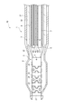
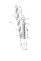
- the side view which shows the medical treatment tool which concerns on one Embodiment of this invention in a partial cross section The figure which shows the holding part of a medical treatment tool partially in cross section.
- a medical treatment instrument 10 As shown in FIGS. 1, 2 ⁇ / b> A, and 2 ⁇ / b> B, a medical treatment instrument 10 according to the present embodiment is provided on an introduction portion 1 (FIG. 1) to be introduced into the body and on the proximal end side of the introduction portion 1.
- a grip 9 (FIGS. 2A and 2B) is provided.
- an introduction unit 1 includes an outer tube 3 having a flexible tube 2 at a distal end portion, and an endoscope as an image information acquisition unit that is provided in the outer tube 3 and can be inserted into and removed from the flexible tube 2.
- a suction tube 5 provided in parallel with the endoscope 4 in the outer tube 3 and selectively inserted into and removed from the endoscope 4 and the flexible tube 2, and the endoscope 4
- the first guide tube 6 as a guide tube for guiding the suction tube 5 to the flexible tube 2, the second guide tube 7 for guiding the suction tube 5 to the flexible tube 2, and the outer periphery of the flexible tube 2.
- An expansion body 8 that expands in the radial direction of the tube 2 is provided.
- the flexible tube 2 includes a plurality of tubular bodies 21 to 24, and these tubular bodies 21 to 24 are configured to be rotatable with respect to each other and connected in the axial direction.
- the flexible tube 2 is connected to an operation means such as a wire (not shown) on the tubular body 21 on the distal end side.
- the flexible tube 2 can be bent by the operation means, and the bending position of the flexible tube 2 can be fixed. It is configured.
- the outer periphery of the flexible tube 2 is tightly covered with a flexible tubular member 25 such as an elastic member, and the fluid sent to the expansion body 8 flows from the gap between the tubular bodies 21 to 24. It does not flow into the flexible tube 2.
- the tubular body 21 on the distal end side and the tubular body 22 on the proximal end side are each provided with rotating shaft portions 211 and 221 that protrude in the coupling direction from one end edge in the coupling direction (the axial direction of the tubular bodies 21 and 22). ing.
- Tubular bodies 23 and 24 having different shapes are alternately arranged between the distal end side tubular body 21 and the proximal end side tubular body 22.
- the tubular body 23 includes a rotating shaft portion 231 that protrudes in the coupling direction from both edges in the coupling direction (the axial direction of the tubular body 23).
- the tubular body 24 includes a rotation support portion 241 whose end edges on both sides in the connecting direction (the axial direction of the tubular body 24) are retracted, and the rotation support portion 241 causes the rotation shafts of the tubular bodies 21 to 23 to rotate. Portions 211, 221, and 231 are supported. Note that a pair of rotation shaft portions 211, 221, 231 and a rotation support portion 241 are provided at positions symmetrical to each other with respect to the central axis of each tubular body 21-24.
- the outer tube 3 is a cylindrical housing portion 31 that houses the guide tubes 6 and 7, and a connecting portion between the housing portion 31 and the flexible tube 2. And a conical reduced diameter portion 32 that is reduced in diameter.
- the flexible tube 2 and the outer tube 3 as described above are obtained, for example, by laser processing the tip side of the reduced diameter portion 32 in a stainless steel tubular member having the reduced diameter portion 32.
- laser processing is used, the introduction part 1 in a state where the tubular bodies 21 to 24 of the flexible tube 2 are connected to each other can be easily obtained simply by cutting the circular tubular member with a laser.
- the endoscope 4 includes an urging member 41 that urges the endoscope 4 in a bending direction, and an imaging unit 42 having an imaging element such as a CCD (Charge Coupled Device) image sensor. And an optical transmission section 43 such as an optical fiber for transmitting light toward the distal end portion of the endoscope 4 and an outer cylinder 44 for housing these elements 41 to 43.
- the endoscope 4 is configured to be bendable by operation means such as a wire (not shown) connected to the distal end portion of the endoscope 4.
- the imaging unit 42 is not limited to this, a digital video camera using another imaging element such as a CMOS (Complementary Metal Oxide Semiconductor) image sensor, an image fiber that acquires and transmits an image using an optical fiber, It may be an imaging system that performs image transmission using an objective lens and a plurality of relay lens optical systems.
- CMOS Complementary Metal Oxide Semiconductor
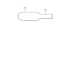
- the biasing member 41 is made of a superelastic alloy such as a nickel titanium alloy or a shape memory alloy, and is curved so as to turn toward the proximal end side without applying an external force. Part. As shown in FIGS. 4A and 4B, the distal end portion 411 of the biasing member 41 has a shape widened with respect to the proximal end side in a plan view, and is thin with respect to the proximal end side in a side view. It is formed in a thin plate shape. By making the tip portion 411 such a shape, it is possible to prevent the tip portion 411 from damaging the outer cylinder 44.
- a superelastic alloy such as a nickel titanium alloy or a shape memory alloy
- the suction tube 5 is a conduit for sucking solids and fluids in the body, and is connected to a suction device such as a suction pump (not shown).
- the first and second guide tubes 6 and 7 are accommodated in the accommodating portion 31 of the outer tube 3 and extend to the reduced diameter portion 32 of the outer tube 3.
- the first guide tube 6 guides the endoscope 4 to the flexible tube 2 while holding the endoscope 4 so as to be able to advance and retreat, and restricting the shape change of the endoscope 4 by the urging member 41.
- the second guide tube 7 holds the suction tube 5 so as to be movable forward and backward.
- the expansion body 8 is made of a flexible material such as a polymer.
- the inside of the expansion body 8 communicates with a flow path 81 provided around the outer tube 3, and fluid is introduced into the expansion body 8 via the flow path 81, so that the expansion body 8 has a diameter. It is configured to expand in the direction.
- the grip portion 9 includes a first operating portion 91 as a position fixing tool that allows the endoscope 4 to be inserted into and removed from the flexible tube 2 and fixes the advance / retreat position of the endoscope 4.
- the suction tube 5 is inserted into and removed from the flexible tube 2 and the second operating portion 92 as a position fixing tool for fixing the advance / retreat position of the suction tube 5 and the expansion body 8 are expanded or contracted and the expanded state of the expansion body 8 is maintained.
- a third operation unit 93 a third operation unit 93.
- the first operation unit 91 and the second operation unit 92 hold the endoscope 4 or the suction tube 5 in the grip unit 9.
- These operation units 91 and 92 are slidably provided toward the outer tube 3 and are configured to be fixed at a position indicated by a solid line and a position indicated by a one-dot chain line in FIG. 2A.
- the endoscope 4 or the suction tube 5 is inserted through the flexible tube 2 when the operation units 91 and 92 are at the solid line positions, and from the flexible tube 2 when the operation units 91 and 92 are at the one-dot chain line positions. Pulled out.
- the third operation part 93 is provided in a fluid introduction path 94 communicating with the flow path 81 for the expansion body 8 so as to be able to advance and retreat. It is comprised so that. Specifically, the third operation portion 93 is provided on one end side of the rod 96 in the fluid introduction path 94 and a rod 96 that is screwed into a screw hole formed in a closing member 95 that closes the fluid introduction path 94.
- the sealing member 97 for sealing the fluid introduction path 94 and a knob portion 98 provided on the other end side of the rod 96 outside the fluid introduction path 94 are provided.
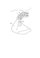
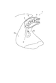
- the operator inserts the introduction portion 1 of the medical treatment instrument 10 from the nostril, and as shown in FIG. 5, the flexible tube 2 and the expansion body 8 are inserted into the sinus PS while the flexible tube 2 is bent. Guide to the narrowed part S of the natural mouth (procedure 1).
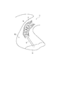
- the operator operates the first operation unit 91 to project the endoscope 4 from the flexible tube 2 and insert the imaging unit 42 of the endoscope 4 into the sinus PS (procedure 2). Then, as shown in FIG. 6, the endoscope 4 is bent by the urging force of the urging member 41, and the imaging unit 42 faces the narrowed portion S side. The operator confirms the state of the stenosis S and the position of the expansion body 8 in the stenosis S based on the image information acquired by the imaging unit 42 in this state (procedure 3).
- the imaging unit 42 of the endoscope 4 can be directed to the stenosis part S without performing an operation of bending the endoscope 4 toward the stenosis part S using a complicated mechanism. It is possible to easily observe the state of the stenosis S occurring in the natural mouth of the paranasal sinus and whether or not the expansion body 8 is disposed at a position including the stenosis S.
- the operator When it is confirmed that the expansion body 8 is positioned in the constriction S, the operator introduces fluid into the expansion body 8 by operating the third operation section 93, as shown in FIG. Then, the expansion body 8 is expanded (procedure 4). At this time, since the imaging unit 42 of the endoscope 4 is maintained in the state of being directed toward the narrowed portion S by the urging force of the urging member 41, the expansion body 8 is detected by the image information acquired by the imaging unit 42. You can observe the expansion.
- the operator acquires image information of the stenosis S after the expansion body 8 is expanded (procedure 5), and based on the image information. Then, it is determined whether or not the stenosis S has been expanded (procedure 6). At this time, it can be visually confirmed that the constriction S is expanded.
- the operator performs the first operation so that the endoscope 4 faces in a direction opposite to the biasing direction of the biasing member 41 (in a direction in which the endoscope 4 is linear).
- the imaging unit 42 is directed to the bottom side of the sinus PS.
- the state in the sinus PS is confirmed (procedure 7).
- the distal end angle of the endoscope 4 can be selectively changed by repeating the forward / backward operation of the first operation unit 91, the inside of the sinuses can be widely observed.
- the endoscope 4 is removed from the flexible tube 2 by operating the first operation unit 91, Pull back into tube 3 (procedure 8). Thereafter, the second operation unit 92 is operated, and the suction tube 5 is inserted through the flexible tube 2 as shown in FIG. 10 (procedure 9), and the reservoir D is sucked with the suction tube 5 (procedure 10). . It is also possible to introduce a fluid such as physiological saline into the suction tube 5 and wash the inside of the sinus PS with the fluid.
- a fluid such as physiological saline
- the above procedures 1, 2, and 7 may be performed. Further, when only the dilation of the constriction S occurring in the natural mouth of the paranasal sinus PS is performed, the above steps 1 to 4 may be performed. Furthermore, it is possible to visually confirm that the stenosis part S has been expanded by carrying out the procedures 5 and 6 continuously, and to reliably confirm that the stenosis part S has been expanded. Furthermore, when only sinusitis treatment is performed, the above procedures 1, 2, 7 to 10 may be performed.
- the medical treatment instrument 10 is introduced into the body while the flexible tube 2 is curved. Part 1 can be inserted.
- the connecting portion of the outer tube 3 with the flexible tube 2 is reduced in diameter to the diameter of the flexible tube 2, the diameter of the distal end portion of the introduction portion 1 can be reduced. Therefore, it is possible to facilitate insertion of the medical treatment instrument 10 into the body while selectively configuring the endoscope 4 and the suction tube 5 so as to be freely inserted into and removed from the flexible tube 2.
- the flexible tube 2 is inserted into the sinus PS when observing in the sinus PS, the flexible tube 2 can be made to follow the shape of the natural mouth of the sinus PS, and the medical treatment can be applied to the sinus PS.
- the introduction part 1 of the tool 10 can be easily inserted.
- the number of treatment tools required for the treatment of sinusitis can be reduced, and the trouble of replacing the treatment tools and The time required for replacement can be shortened.
- the endoscope 4 is inserted through the inserted flexible tube 2, the state in the sinus PS can be confirmed without performing a surgical procedure.
- the body 8 in order to expand the expansion body 8 after confirming the position of the expansion body 8 in the narrowed portion S of the natural mouth of the sinus cavity PS based on the image information from the endoscope 4 inserted into the sinus cavity PS, The body 8 can be expanded at an appropriate position of the constriction S. For this reason, the dilation treatment of the constriction part S can be performed effectively.
- the state in the sinus PS can be confirmed based on the acquired image information in the sinus PS. For this reason, the effective treatment according to the state in the paranasal sinus PS can be performed.
- the present invention is not limited to the above-described embodiment, and modifications, improvements, and the like within the scope that can achieve the object of the present invention are included in the present invention.
- the expansion body 8 is provided.
- the expansion body 8 is not essential except when performing the expansion treatment of the stenosis S, and the medical treatment instrument 10 is configured without the expansion body 8. May be.
- the endoscope 4 includes the biasing member 41.
- the biasing member 41 is not provided. May be.
- the urging member 41 may be made of a material other than the nickel titanium alloy or the shape memory alloy as long as the urging member 41 can be urged in the direction in which the endoscope 4 is bent.
- the flexible tube 2 was comprised with metals, such as stainless steel, as long as it has flexibility, you may comprise with other members, such as resin and another metal. Further, in place of the suction tube 5, another member such as a guide wire may be held in the second guide tube 7 so as to freely advance and retract.
- the medical treatment instrument 10 is used for observation in the sinuses, dilation of a narrowed portion generated in the natural mouth of the sinuses, and treatment of sinusitis, but observation of other parts of the body. And may be used for treatment.
- the present invention can be used for medical treatment tools used for diagnosis and treatment of the paranasal sinuses, as well as other medical treatment tools for diagnosis or treatment that do not involve surgical treatment.
Landscapes
- Health & Medical Sciences (AREA)
- Life Sciences & Earth Sciences (AREA)
- Surgery (AREA)
- Biomedical Technology (AREA)
- Medical Informatics (AREA)
- Optics & Photonics (AREA)
- Pathology (AREA)
- Radiology & Medical Imaging (AREA)
- Biophysics (AREA)
- Engineering & Computer Science (AREA)
- Physics & Mathematics (AREA)
- Heart & Thoracic Surgery (AREA)
- Nuclear Medicine, Radiotherapy & Molecular Imaging (AREA)
- Molecular Biology (AREA)
- Animal Behavior & Ethology (AREA)
- General Health & Medical Sciences (AREA)
- Public Health (AREA)
- Veterinary Medicine (AREA)
- Endoscopes (AREA)
- Surgical Instruments (AREA)
- Media Introduction/Drainage Providing Device (AREA)
Applications Claiming Priority (2)
| Application Number | Priority Date | Filing Date | Title |
|---|---|---|---|
| JP2012-070051 | 2012-03-26 | ||
| JP2012070051A JP2015109884A (ja) | 2012-03-26 | 2012-03-26 | 医療用処置具 |
Publications (1)
| Publication Number | Publication Date |
|---|---|
| WO2013146351A1 true WO2013146351A1 (fr) | 2013-10-03 |
Family
ID=49259612
Family Applications (1)
| Application Number | Title | Priority Date | Filing Date |
|---|---|---|---|
| PCT/JP2013/057417 Ceased WO2013146351A1 (fr) | 2012-03-26 | 2013-03-15 | Instrument de traitement médical |
Country Status (2)
| Country | Link |
|---|---|
| JP (1) | JP2015109884A (fr) |
| WO (1) | WO2013146351A1 (fr) |
Citations (3)
| Publication number | Priority date | Publication date | Assignee | Title |
|---|---|---|---|---|
| JPH06503246A (ja) * | 1990-12-17 | 1994-04-14 | カーディオヴァスキュラー イメイジング システムズ インコーポレイテッド | 低輪郭の遠位端部を有する血管カテーテル |
| JP2006513784A (ja) * | 2003-03-18 | 2006-04-27 | ジョムド ゲゼルシャフト ミット ベシュレンクター ハフツンク | 機能測定ワイヤとともに使用される補助ルーメンを備えたカテーテル |
| JP2009505691A (ja) * | 2005-07-29 | 2009-02-12 | アクラレント インコーポレイテッド | 耳、鼻及び咽喉の疾患を治療する方法及び器具 |
-
2012
- 2012-03-26 JP JP2012070051A patent/JP2015109884A/ja active Pending
-
2013
- 2013-03-15 WO PCT/JP2013/057417 patent/WO2013146351A1/fr not_active Ceased
Patent Citations (3)
| Publication number | Priority date | Publication date | Assignee | Title |
|---|---|---|---|---|
| JPH06503246A (ja) * | 1990-12-17 | 1994-04-14 | カーディオヴァスキュラー イメイジング システムズ インコーポレイテッド | 低輪郭の遠位端部を有する血管カテーテル |
| JP2006513784A (ja) * | 2003-03-18 | 2006-04-27 | ジョムド ゲゼルシャフト ミット ベシュレンクター ハフツンク | 機能測定ワイヤとともに使用される補助ルーメンを備えたカテーテル |
| JP2009505691A (ja) * | 2005-07-29 | 2009-02-12 | アクラレント インコーポレイテッド | 耳、鼻及び咽喉の疾患を治療する方法及び器具 |
Also Published As
| Publication number | Publication date |
|---|---|
| JP2015109884A (ja) | 2015-06-18 |
Similar Documents
| Publication | Publication Date | Title |
|---|---|---|
| CN102112041B (zh) | 摆动棱镜内窥镜 | |
| US20150018616A1 (en) | Medical treatment instrument | |
| CN102137615B (zh) | 用于内窥镜的器械 | |
| JP5327986B2 (ja) | 内視鏡用挿入補助具 | |
| EP1854500A1 (fr) | Dispositif auxiliaire d'insertion/de retrait d'un outil de traitement | |
| CN106163364B (zh) | 腹腔内窥镜装置以及内窥镜系统 | |
| CN113425224A (zh) | 医疗系统、装置和相关方法 | |
| CN110167415B (zh) | 医疗系统、装置和相关方法 | |
| US20150011827A1 (en) | Medical treatment instrument | |
| JP5781249B2 (ja) | 医療器具 | |
| JP6778933B2 (ja) | 使い捨てシースデバイス | |
| EP3446741A1 (fr) | Ensemble de fil d'âme pour fil de guidage | |
| US20130281778A1 (en) | Treatment instrument for medical use and method | |
| JP5498422B2 (ja) | 内視鏡用挿入補助具 | |
| CN119073866A (zh) | 具有一体式成像和冲洗特征结构的器械 | |
| JP7662928B2 (ja) | 耳鼻咽喉ツールの偏向機構 | |
| WO2013146351A1 (fr) | Instrument de traitement médical | |
| JP7536874B2 (ja) | 耳鼻咽喉ツールを偏向させる際のプルワイヤのねじれ防止 | |
| JP7589882B2 (ja) | 耳鼻咽喉ツールの非円形作業チャネル | |
| US10596363B2 (en) | Medical treatment tool | |
| JP2021168711A (ja) | 内視鏡 | |
| JP4847175B2 (ja) | 内視鏡システム、及び内視鏡挿入補助具 | |
| WO2013161579A1 (fr) | Instrument de traitement médical | |
| JP2006247290A (ja) | 内視鏡カバー及び内視鏡カバーを備えた内視鏡装置 | |
| JP2013226184A (ja) | 医療用処置具 |
Legal Events
| Date | Code | Title | Description |
|---|---|---|---|
| 121 | Ep: the epo has been informed by wipo that ep was designated in this application |
Ref document number: 13768754 Country of ref document: EP Kind code of ref document: A1 |
|
| NENP | Non-entry into the national phase |
Ref country code: DE |
|
| 122 | Ep: pct application non-entry in european phase |
Ref document number: 13768754 Country of ref document: EP Kind code of ref document: A1 |
|
| NENP | Non-entry into the national phase |
Ref country code: JP |