WO2013146406A1 - 導波路結合msm型フォトダイオード - Google Patents
導波路結合msm型フォトダイオード Download PDFInfo
- Publication number
- WO2013146406A1 WO2013146406A1 PCT/JP2013/057622 JP2013057622W WO2013146406A1 WO 2013146406 A1 WO2013146406 A1 WO 2013146406A1 JP 2013057622 W JP2013057622 W JP 2013057622W WO 2013146406 A1 WO2013146406 A1 WO 2013146406A1
- Authority
- WO
- WIPO (PCT)
- Prior art keywords
- msm
- photodiode
- waveguide
- layer
- coupled
- Prior art date
- Legal status (The legal status is an assumption and is not a legal conclusion. Google has not performed a legal analysis and makes no representation as to the accuracy of the status listed.)
- Ceased
Links
Images





Classifications
-
- H—ELECTRICITY
- H10—SEMICONDUCTOR DEVICES; ELECTRIC SOLID-STATE DEVICES NOT OTHERWISE PROVIDED FOR
- H10F—INORGANIC SEMICONDUCTOR DEVICES SENSITIVE TO INFRARED RADIATION, LIGHT, ELECTROMAGNETIC RADIATION OF SHORTER WAVELENGTH OR CORPUSCULAR RADIATION
- H10F30/00—Individual radiation-sensitive semiconductor devices in which radiation controls the flow of current through the devices, e.g. photodetectors
- H10F30/20—Individual radiation-sensitive semiconductor devices in which radiation controls the flow of current through the devices, e.g. photodetectors the devices having potential barriers, e.g. phototransistors
- H10F30/21—Individual radiation-sensitive semiconductor devices in which radiation controls the flow of current through the devices, e.g. photodetectors the devices having potential barriers, e.g. phototransistors the devices being sensitive to infrared, visible or ultraviolet radiation
- H10F30/22—Individual radiation-sensitive semiconductor devices in which radiation controls the flow of current through the devices, e.g. photodetectors the devices having potential barriers, e.g. phototransistors the devices being sensitive to infrared, visible or ultraviolet radiation the devices having only one potential barrier, e.g. photodiodes
- H10F30/227—Individual radiation-sensitive semiconductor devices in which radiation controls the flow of current through the devices, e.g. photodetectors the devices having potential barriers, e.g. phototransistors the devices being sensitive to infrared, visible or ultraviolet radiation the devices having only one potential barrier, e.g. photodiodes the potential barrier being a Schottky barrier
- H10F30/2275—Individual radiation-sensitive semiconductor devices in which radiation controls the flow of current through the devices, e.g. photodetectors the devices having potential barriers, e.g. phototransistors the devices being sensitive to infrared, visible or ultraviolet radiation the devices having only one potential barrier, e.g. photodiodes the potential barrier being a Schottky barrier being a metal-semiconductor-metal [MSM] Schottky barrier
-
- H—ELECTRICITY
- H10—SEMICONDUCTOR DEVICES; ELECTRIC SOLID-STATE DEVICES NOT OTHERWISE PROVIDED FOR
- H10F—INORGANIC SEMICONDUCTOR DEVICES SENSITIVE TO INFRARED RADIATION, LIGHT, ELECTROMAGNETIC RADIATION OF SHORTER WAVELENGTH OR CORPUSCULAR RADIATION
- H10F39/00—Integrated devices, or assemblies of multiple devices, comprising at least one element covered by group H10F30/00, e.g. radiation detectors comprising photodiode arrays
- H10F39/80—Constructional details of image sensors
- H10F39/806—Optical elements or arrangements associated with the image sensors
-
- H—ELECTRICITY
- H10—SEMICONDUCTOR DEVICES; ELECTRIC SOLID-STATE DEVICES NOT OTHERWISE PROVIDED FOR
- H10F—INORGANIC SEMICONDUCTOR DEVICES SENSITIVE TO INFRARED RADIATION, LIGHT, ELECTROMAGNETIC RADIATION OF SHORTER WAVELENGTH OR CORPUSCULAR RADIATION
- H10F77/00—Constructional details of devices covered by this subclass
- H10F77/10—Semiconductor bodies
- H10F77/16—Material structures, e.g. crystalline structures, film structures or crystal plane orientations
- H10F77/162—Non-monocrystalline materials, e.g. semiconductor particles embedded in insulating materials
- H10F77/164—Polycrystalline semiconductors
-
- H—ELECTRICITY
- H10—SEMICONDUCTOR DEVICES; ELECTRIC SOLID-STATE DEVICES NOT OTHERWISE PROVIDED FOR
- H10F—INORGANIC SEMICONDUCTOR DEVICES SENSITIVE TO INFRARED RADIATION, LIGHT, ELECTROMAGNETIC RADIATION OF SHORTER WAVELENGTH OR CORPUSCULAR RADIATION
- H10F77/00—Constructional details of devices covered by this subclass
- H10F77/10—Semiconductor bodies
- H10F77/16—Material structures, e.g. crystalline structures, film structures or crystal plane orientations
- H10F77/162—Non-monocrystalline materials, e.g. semiconductor particles embedded in insulating materials
- H10F77/166—Amorphous semiconductors
-
- H—ELECTRICITY
- H10—SEMICONDUCTOR DEVICES; ELECTRIC SOLID-STATE DEVICES NOT OTHERWISE PROVIDED FOR
- H10F—INORGANIC SEMICONDUCTOR DEVICES SENSITIVE TO INFRARED RADIATION, LIGHT, ELECTROMAGNETIC RADIATION OF SHORTER WAVELENGTH OR CORPUSCULAR RADIATION
- H10F77/00—Constructional details of devices covered by this subclass
- H10F77/40—Optical elements or arrangements
- H10F77/413—Optical elements or arrangements directly associated or integrated with the devices, e.g. back reflectors
-
- G—PHYSICS
- G02—OPTICS
- G02B—OPTICAL ELEMENTS, SYSTEMS OR APPARATUS
- G02B6/00—Light guides; Structural details of arrangements comprising light guides and other optical elements, e.g. couplings
- G02B6/10—Light guides; Structural details of arrangements comprising light guides and other optical elements, e.g. couplings of the optical waveguide type
- G02B6/12—Light guides; Structural details of arrangements comprising light guides and other optical elements, e.g. couplings of the optical waveguide type of the integrated circuit kind
- G02B6/12004—Combinations of two or more optical elements
Definitions
- the present invention relates to a waveguide coupled MSM type photodiode, and in particular, converts an optical signal including infrared light required for information processing using an optical wiring within an LSI chip or between chips into an electrical signal at high speed.
- the present invention relates to a photodiode to be converted.
- Silicon-germanium photodiodes ie silicon-germanium photodiodes, monolithically integrated on the same chip as the CMOS circuit, ie silicon-germanium photodiodes, are one attractive for hybrid receivers such as InGaAs photodiodes connected to CMOS or GaAs circuits. Is an alternative.
- a monolithic integrated circuit photoreceiver can be manufactured using a standard silicon processing process, and is expected to be manufactured at a lower cost than a hybrid photoreceiver.
- Photodiodes are widely used as devices that convert optical signals into electrical signals at high speed.
- a typical example is a pin type photodiode.
- the pin-type photodiode has a structure in which an i layer made of an intrinsic semiconductor is sandwiched between a p layer made of a p-type semiconductor and an n layer made of an n-type semiconductor.
- a reverse bias voltage is applied to this laminated structure by a bias power source, almost the entire area of the high-resistance i layer becomes a charge carrier depletion layer. Incident photons are absorbed mainly by the i layer and generate electron-hole pairs.
- the generated electrons and holes drift in the depletion layer in opposite directions by the reverse bias voltage to generate currents, and are detected as signal voltages by the load resistance.
- the main factors that limit the photoelectric conversion response speed are the circuit time constant determined by the product of the load resistance and the capacitance produced by the depletion layer, and the carrier transit time required for electrons and holes to pass through the depletion layer. .
- a Schottky photodiode As a photodiode having a short carrier travel time, a Schottky photodiode can be given.
- a Schottky photodiode has a structure in which a semi-transparent metal film is in contact with an n layer or an n ⁇ layer of a semiconductor.
- a Schottky barrier is formed in the vicinity of the interface between the n layer or the n ⁇ layer and the semitransparent metal film. In the vicinity of this Schottky barrier, n-layer or n ⁇ -layer electrons diffuse from the translucent metal film to form a depletion layer.
- the i layer, ie, the depletion layer needs to have a sufficient thickness for photon absorption, whereas in Schottky photodiodes, the depletion layer can be made thin. Therefore, the carrier travel time can be shortened by using a Schottky photodiode as described above.
- Non-Patent Document 1 in pin type photodiodes, attempts have been made to reduce the electrode spacing by using a lateral electrode structure in order to make the depletion layer thin. However, it is difficult to increase the sensitivity.
- the value of the additional resistor is decreased in order to shorten the circuit time constant in the pin-type and Schottky-type photodiodes, the voltage of the reproduced signal that can be extracted decreases. Therefore, reduction of the electric capacity of the depletion layer is important for improving the SN ratio of the reproduction signal and reducing the reading error.
- the depletion layer is thinned in order to shorten the carrier travel time, the electric capacity increases. Therefore, in order to increase the speed, it is necessary to reduce the area of the depletion layer or the Schottky junction.
- the area of the Schottky junction is reduced, there is a problem that the use efficiency of the signal light is lowered, and as a result, the SN ratio of the reproduction signal is deteriorated.
- MSM metal-semiconductor-metal
- a carrier depletion layer is formed by a voltage applied between two adjacent electrodes as described above, and photocarriers are swept to the electrode by an internal electric field. Therefore, in order to achieve high speed, it is important to reduce the distance between two adjacent electrodes, reduce the thickness of the semiconductor light absorption layer, and shorten the travel time of the photo carrier.
- MSM type photodiode provides flatness and compatibility with silicon LSI.
- it is necessary to reduce the light reflection by the MSM electrode and realize high speed and high efficiency.
- the spacing between the MSM electrodes is reduced and the light absorption layer is thinned, and the applied voltage is increased to shorten the carrier transit time; and It is necessary to reduce the circuit time constant by reducing the light receiving area, that is, the junction capacitance.
- the light receiving sensitivity and the high speed are in a trade-off relationship, and it is difficult to satisfy both the light receiving sensitivity and the high speed.
- An object of the present invention is to provide a device structure that realizes an MSM type photodiode coupled with an optical waveguide with high efficiency and satisfies both light receiving sensitivity and high speed at a low voltage. It is another object of the present invention to provide a photodiode that achieves high integration and low power consumption by application to a differential photodiode.
- the waveguide-coupled MSM type photodiode of the present invention has a structure in which a semiconductor light absorption layer and an optical waveguide core layer are adjacently optically coupled, and MSM junctions arranged on the semiconductor light absorption layer are spaced apart.
- the formed photodiode is characterized in that a voltage is set so that a reverse bias is applied to the MSM electrode arranged on the light incident side among the MSM electrodes arranged at the interval.
- the reverse bias indicates a state where a negative voltage is set when the semiconductor light absorption layer is an n-type semiconductor, and a state where a positive voltage is applied when the semiconductor light absorption layer is a p-type semiconductor.
- positive or negative bias may be applied.
- p-type conductivity type it is extremely difficult to reduce the impurity concentration to about 10 14 / cm 3 or less.
- a photocarrier can be swept at high speed and high efficiency in an MSM type photodiode optically coupled to an integrated optical waveguide, and a high speed and high efficiency photodiode can be realized at a low voltage.
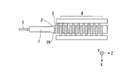
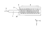
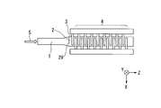
- FIG. 1 is a cross-sectional view of a waveguide coupled MSM photodiode according to a first embodiment of the present invention. It is a top view of the waveguide coupling MSM type photodiode which is the first embodiment of the present invention. It is sectional drawing of the waveguide coupling MSM type
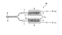
- FIG. 9 is a configuration diagram in which a waveguide-coupled MSM photodiode according to a fifth embodiment of the present invention optically coupled to a differential optical signal is a balanced differential photodiode. It is a block diagram which made the waveguide coupling MSM type photodiode which concerns on 6th Embodiment of this invention optically coupled with the differential optical signal into the dual type
- FIG. 6 is a diagram showing an electric field distribution in a semiconductor light absorption layer when a positive bias is applied to an MSM electrode arranged on the light incident side in the waveguide coupled MSM type photodiode of the present invention.
- FIG. 6 is a diagram showing an electric field distribution in a semiconductor light absorption layer when a reverse bias is applied to an MSM electrode arranged on the light incident side in the waveguide coupled MSM type photodiode of the present invention.
- the waveguide coupled MSM type photodiode of the present invention it is a diagram showing the frequency characteristic of the reception sensitivity when a positive bias is applied to the MSM electrode arranged on the light incident side.
- the waveguide coupled MSM type photodiode of the present invention it is a diagram showing the frequency characteristics of reception sensitivity when a reverse bias is applied to the MSM electrode arranged on the light incident side.
- (First embodiment) 1 and 2 show a structural example of an MSM type photodiode (waveguide coupled MSM type photodiode) 51 according to the first embodiment of the present invention.
- the MSM photodiode 51 is formed on a semiconductor light absorption layer 2 that is optically coupled to an adjacent optical waveguide core layer 1.
- the optical waveguide core layer 1 is formed on a buried oxide layer 12 laminated on a support substrate 11.
- the MSM type photodiode 51 is a photodiode in which MSM junctions arranged on the semiconductor light absorption layer 2 with an interval are formed.
- the voltage is set such that a reverse bias is applied to the MSM electrode (1) 3 arranged on the light incident side (input optical signal 5 side) among the MSM electrodes 3 and 4 arranged at intervals. .
- the optical waveguide core layer 1 and the semiconductor light absorption layer 2 are formed by being laminated in the direction perpendicular to the substrate, and are evanescently coupled.
- the light propagating through the optical waveguide core layer 1 alternates in the optical mode field between the optical waveguide core layer 1 and the semiconductor light absorption layer 2 at a period corresponding to the refractive index difference from the semiconductor light absorption layer 2. Will move on.
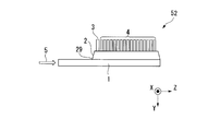
- (Second Embodiment) 3 and 4 show a structure example of the MSM type photodiode 52 according to the second embodiment of the present invention.
- the same components as those of the MSM photodiode 51 of the first embodiment are denoted by the same reference numerals, and Description is omitted.
- the MSM electrodes 3 and 4 are formed so that the width of the MSM electrode (1) 3 disposed on the light incident side is larger than the width of the other MSM electrodes 4. .
- the width of the MSM electrode (1) 3 the region where the internal electric field strength is large is expanded in the photocarrier generation region due to optical coupling, and the reception sensitivity and frequency band are improved.
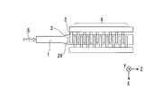
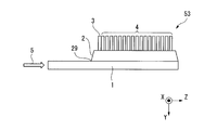
- (Third embodiment) 5 and 6 show a structural example of the MSM type photodiode 53 according to the third embodiment.
- the interval between the MSM electrode (1) 3 arranged on the light incident side and the adjacent MSM electrode 4 is smaller than the interval between the other adjacent MSM electrodes 4.
- MSM electrodes 3 and 4 are formed.
- FIG. 7 and 8 show a structural example of the MSM photodiode 54 according to the fourth embodiment.
- the semiconductor light absorption layer 2 and the optical waveguide core layer 1 are optically coupled adjacent to the supporting substrate (not shown) in the horizontal direction, and a reverse bias is applied to the MSM electrode (1).
- the voltage is set so as to be applied.
- the distance from the end 29 of the light absorption layer 2 is ⁇ / n eff , where ⁇ is the wavelength of incident light and n eff is the effective refractive index felt by the optical signal electric field in the semiconductor light absorption layer 2.
- ⁇ is the wavelength of incident light
- n eff is the effective refractive index felt by the optical signal electric field in the semiconductor light absorption layer 2.
- the internal electric field strength can be increased in a region where light is mode-coupled between the optical waveguide core layer 1 and the semiconductor light absorption layer 2 and photocarriers are generated most frequently.
- the reception sensitivity and frequency band of the MSM type photodiode are significantly improved.
- the semiconductor light absorption layer 2 at least one layer selected from the group consisting of Ge, Si 1-x Ge x , Si, InGaAs, GaN, GaAs, GaInP, and InP can be used.
- the MSM electrodes 3 and 4 can be made of at least one layer selected from aluminum, silver, gold, copper, tungsten, titanium, titanium nitride, and nickel, or at least two alloy layers.
- FIG. 9 and 10 are configuration diagrams of an optical receiver circuit in which a differential optical signal transmitted through two optical waveguides and the waveguide coupled MSM type photodiode of the present invention are optically coupled. is there.
- FIG. 9 shows a receiving circuit configuration of a balanced differential light receiver 55 according to a fifth embodiment of the present invention
- FIG. 10 shows a receiving circuit of a dual differential light receiver 56 according to a sixth embodiment of the present invention. The configuration is shown.
- the MSM electrodes disposed on the light incident side of the two MSM photodiodes since two MSM photodiodes are electrically connected in parallel, the MSM electrodes disposed on the light incident side of the two MSM photodiodes.
- the voltage is set so that a reverse bias is applied to (1-1) 7 and the MSM electrode (1-2) 8.
- a characteristic difference between two photodiodes hinders performance improvement.
- bias applied to the MSM electrode (1-1) 7 and the MSM electrode (1-2) 8 on the light incident side (differential optical signal 6 side) in the two photodiodes By setting the voltage to be a reverse bias, it is possible to match the frequency characteristics and the light receiving sensitivity, and a good differential output waveform can be obtained.
- two MSM type photodiodes are electrically connected in series.
- the electrodes are arranged so that a reverse bias is applied to the MSM electrode (1-3) 9 and the MSM electrode (1-4) 10 arranged on the light incident side, and the bias voltage is set.
- an optical wiring system on an LSI including the MSM type photodiodes 51, 52, 53, and 54 of each embodiment in a light receiving unit can be configured.
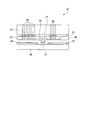
- FIG. 11 shows a configuration of an optical interconnection module 67 according to the seventh embodiment.
- the optical interconnection module 67 includes a photodiode / light source mounting board (Si substrate) 28 on which the waveguide coupled MSM photodiode 17 of the present invention is formed, and a photodiode / light source mounting board 28.
- a waveguide-coupled MSM photodiode 17 and a monolithically formed LSI electronic circuit includes a VCSEL light source 18, which is a light source of the optical interconnection module 67, a light source modulation electric wiring layer 22, a photodiode electric wiring layer 23, and the like.
- the optical interconnection module 67 includes the photodiode / light source mounting board 28, the LSI package 21, and the LSI mounting board 26 described above, as shown in FIG.
- the LSI package 21 includes a light source modulation electrical wiring via 19 and a photodiode electrical wiring via 20.
- the LSI mounting board 26 includes an optical signal input fiber 25, an optical signal output fiber 24, and a concave mirror 27.
- the light source modulation electrical wiring layer 22 is electrically connected to the light source modulation electrical wiring via 19.
- An electric signal from the LSI is converted into an optical signal by the VCSEL light source 18 having an electric modulation mechanism through the light source modulation electric wiring via 19 and the light source modulation electric wiring layer 22.
- the optical signal is reflected by the concave mirror 27 and sent to the optical signal output fiber 24.
- the VCSEL light source 18 can be replaced with another known light emitting mechanism that modulates light by electricity, for example, a Mach-Zehnder type modulator that modulates light from an external light source by an electro-optic effect or a thermo-optic effect.
- a known optical device such as a planar optical waveguide can be used instead of the optical signal input fiber 25.
- a condensing mechanism such as a convex lens can be used instead of the concave mirror 27.
- a preamplifier for amplifying an electric signal can be arranged in the middle of the electric wiring layer 23 for the photodiode after the waveguide coupled MSM type photodiode 17.
- An optical signal from the optical signal input fiber 25 is applied to the waveguide coupled MSM photodiode 17 by a concave mirror 27 and a grating coupler (not shown).
- the photodiode electrical wiring layer 23 in contact with the waveguide coupled MSM photodiode 17 is electrically connected to an LSI photodiode electrical wiring via 20. For this reason, the optical signal received by the waveguide coupled MSM type photodiode 17 is converted into an electric signal and sent to the LSI.
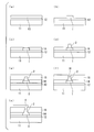
- 12 (a) to 12 (g) are cross-sectional views showing a method of manufacturing the waveguide coupled MSM photodiode 51 according to the first embodiment of the present invention.
- a non-doped SOI substrate in which a support substrate 11, a buried oxide layer 12, and a non-doped semiconductor silicon 13 are stacked is prepared.
- the SOI substrate may be a substrate having a sufficiently low doping concentration.
- a p-type SOI substrate having a resistivity of 1 to 10 o ⁇ ⁇ cm and a doping concentration of 10 15 to 10 16 / cm 3 is used. Shall.
- resist patterning and reactive ion etching are performed by electron beam lithography or light exposure to form the optical waveguide core layer 1.
- a SiO 2 film is formed by a low pressure chemical vapor synthesis (low pressure CVD) method or the like. Thereafter, an opening is formed in the Ge growth area by reactive ion etching, the surface of the SOI layer is exposed, and an oxide film mask 14 for Ge selective growth is formed.
- low pressure CVD low pressure chemical vapor synthesis
- Ge is formed on the oxide film mask 14 so as to have a thickness of about 1 ⁇ m by an ultrahigh vacuum chemical vapor deposition (UHV-CVD) method or a low pressure CVD method.
- UHV-CVD ultrahigh vacuum chemical vapor deposition
- a film is formed in the opening.
- a Si light absorption layer 2 is formed by laminating a Si layer on the Ge layer by 10 to 50 nm.
- an oxide film clad 15 covering the oxide film mask 14 and the semiconductor light absorption layer 2 is laminated with a thickness of 1 ⁇ m.
- a contact hole 16 is formed in a region where the MSM electrode and the Ge / Si layer are in electrical contact by photolithography and reactive ion etching.
- the size of the contact hole 16 is, for example, 1 ⁇ m ⁇ 5 ⁇ m.
- the spacing between contact holes is about 0.8 ⁇ m.
- a Ti / TiN / Al film which is an MSM electrode material, is formed to a thickness of about 1 ⁇ m by sputtering or the like so as to fill the contact hole. Thereafter, a Ti / TiN / Al film (1 ⁇ m) is processed by photolithography and reactive ion etching so as to function as an MSM electrode.
- Example 1 The steps of FIGS. 12A to 12G were performed to manufacture the waveguide coupled MSM type photodiode 51 according to the first embodiment of the present invention.
- the bias voltage is set so that a reverse bias is applied to the MSM electrode (1) 3 which is the region where the optical mode field first moves from the optical waveguide core layer 1 to the semiconductor light absorption layer 2. This makes it possible to match the region where the most photocarriers are generated due to light absorption with the region where the internal electric field is large due to the reverse bias voltage. % High reception efficiency was obtained.
- Si is used as the optical waveguide core layer 1 and Ge is used as the semiconductor light absorption layer 2. It is known that when Si 1-x Ge x or Ge is formed on the Si layer by selective growth, a tapered shape called a facet is generated.
- the incident light wavelength is ⁇ and the effective refractive index felt by the optical signal electric field in the semiconductor light absorption layer is n eff , the light is disposed on the semiconductor light absorption layer 2 with a gap.
- the distance between the MSM electrode (1) 3 disposed on the light incident side of the MSM electrodes 3 and 4 and the end portion 29 of the semiconductor light absorption layer 2 was set to be ⁇ / n eff or less.
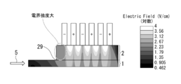
- FIG. 13A and 13B show a waveguide coupled MSM type photodiode formed on a semiconductor light absorption layer 2 optically coupled to an adjacent optical waveguide core layer 1 as shown in FIG. 13A. Shows the electric field distribution in the semiconductor light absorption layer when a positive bias of + 1V is applied to the MSM electrode (1) 3 arranged on the light incident side and when a reverse bias of -1V is applied as shown in FIG. 13B. ing. At this time, the distance between the MSM electrodes was 1.0 ⁇ m, the optical coupling length was 30 ⁇ m, and the Ge layer thickness was 1 ⁇ m.
- FIG. 13A when a positive bias is applied, the current flows in the forward direction in the optical coupling portion in the semiconductor light absorption layer, so the internal electric field is reduced.
- FIG. 13B when a reverse bias was applied, the Schottky barrier was enhanced and the internal electric field was also increased. At this time, light absorption occurs most at the optical coupling portion in the semiconductor light absorption layer, and a large amount of photocarriers are generated. Therefore, in the present invention, by increasing the internal electric field strength in the photocarrier generation region, the photocarrier travel time is shortened, a photodiode operating at high speed is realized, and a higher light is applied by applying a lower voltage. It was confirmed that reception sensitivity could be obtained.
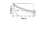
- FIG. 14A and 14B show a case where a positive bias is applied to the MSM electrode (1) 3 arranged on the light incident side (FIG. 14A) and a reverse bias is applied to the waveguide coupled MSM type photodiode described above.
- the frequency characteristic of the receiving sensitivity of (FIG. 14B) is shown.
- the frequency band is 6 to 7 GHz with respect to 5 V applied, whereas when a ⁇ 5 V reverse bias is applied, the frequency band of reception sensitivity is improved to 10 GHz. . That is, in the waveguide coupled MSM type photodiode, by setting the voltage so that a reverse bias is applied to the MSM electrode (1) 3 disposed on the light incident side, the internal electric field strength in the photocarrier generation region is increased. Thus, it was confirmed that the frequency band was improved.
- Example 2 In the waveguide coupled MSM photodiode 52 according to the second embodiment of the present invention, the size of the MSM electrode (1) 3 disposed on the light incident side is increased, and the bias voltage is set so that a reverse bias is applied. did. As a result, it was confirmed that in the photocarrier generation region due to optical coupling, the region where the internal electric field strength was large was expanded, and the reception sensitivity and frequency band were improved.
- the frequency band of the waveguide coupled MSM type photodiode 52 can be expanded by reducing the distance between the MSM electrodes 4 and the film thickness of the semiconductor light absorption layer 2.
- the spacing between the electrodes is fixed to 0.8 to 1.0 ⁇ m, and the size of the MSM electrode (1) 3 disposed on the light incident side is set to 1.2 to 1.5 ⁇ m.
- Example 3 In the waveguide coupled MSM photodiode 53 according to the third embodiment of the present invention, the interval between the MSM electrode (1) 3 disposed on the light incident side and the adjacent MSM electrode 4 is reduced as described above. As a result, the internal electric field strength in the photocarrier generation region due to optical coupling increases, and the reception sensitivity and frequency band are improved.
- the distance between the MSM electrodes 4 was 0.8 ⁇ m, and the distance between the MSM electrode (1) 3 disposed on the light incident side and the adjacent MSM electrode 4 was 0.6 ⁇ m.
- the frequency band was improved from 12 GHz to 15 GHz, and the bias voltage was reduced from -3 V to -2 V, and it was confirmed that high speed and low power consumption could be realized.
- Example 4 In the waveguide coupled MSM type photodiode 54 according to the fourth embodiment of the present invention, by applying a reverse bias of ⁇ 5 V to the MSM electrode (1) 3 in the light incident part where a large amount of photocarriers are generated, A high-speed operation of about 40 GHz was obtained. At this time, the interval between the MSM electrodes was set to 0.5 ⁇ m.
- the two waveguide-coupled MSM photodiodes are electrically connected in parallel, so that the MSM electrode (1-1) 7 and the MSM electrode ( 1-2) A reverse bias voltage of ⁇ 3 V was set to 8.
- a characteristic difference between two photodiodes is generally a problem.
- the bias voltage applied to the light incident side MSM electrode (1-1) 7 and MSM electrode (1-2) 8 in the two photodiodes is set to a reverse bias.
- Example 6 In the dual-type differential photodetector 56 according to the sixth embodiment of the present invention, a reverse bias is applied to the MSM electrode (1-3) 9 and the MSM electrode (1-4) 10 arranged on the light incident side.
- the electrodes were arranged as described above, and a bias voltage of ⁇ 6V was set.
- ⁇ 6V bias voltage
- the frequency characteristics of the two photodiodes almost coincided with 12.3 GHz and 12.5 GHz, and the light receiving sensitivity could be matched with about 0.8 A / W.
- a good differential output waveform was obtained.
- a good eye pattern of 10 Gpbs was obtained in combination with an inverter type transimpedance circuit.
- the waveguide coupled MSM type photodiode According to the waveguide coupled MSM type photodiode according to the present invention, it is possible to realize a photodiode coupled with an optical waveguide with high efficiency, and to provide a device structure that achieves both light receiving sensitivity and high speed at a low voltage.
Landscapes
- Light Receiving Elements (AREA)
Description
従って、高速性を実現するためには、隣接する2つの電極間隔を小さくすると共に、半導体光吸収層の膜厚を小さくし、フォトキャリアの走行時間を短くすることが重要である。
ここで、逆バイアスとは、半導体光吸収層がn型半導体である場合は負の電圧を設定した状態、また、p型半導体である場合は正の電圧を印加した状態を指す。また、真性半導体の場合は、正・負のいずれかのバイアス印加でも良いが、実際には、不純物濃度を1014/cm3以下程度にすることは極めて困難であるため、通常はn型あるいはp型の導電タイプを示す。
なお、以下の説明で用いる図面は、特徴をわかりやすくするために、便宜上特徴となる部分を拡大して示している場合があり、各構成要素の寸法比率などが実際と同じであるとは限らない。
図1および図2は、本発明の第1実施形態であるMSM型フォトダイオード(導波路結合MSM型フォトダイオード)51の構造例を示している。
図1に示すように、MSM型フォトダイオード51は、隣接する光導波路コア層1と光結合した半導体光吸収層2上に形成されている。光導波路コア層1は、支持基板11に積層された埋め込み酸化層12上に形成されている。また、MSM型フォトダイオード51は、半導体光吸収層2上に間隔をおいて配置されたMSM接合を形成したフォトダイオードである。間隔をおいて配置されたMSM電極3,4のうち、光入射側(入力光信号5側)に配置されたMSM電極(1)3に逆バイアスが印加されるように、電圧設定されている。
図3および図4は、本発明の第2実施形態であるMSM型フォトダイオード52の構造例を示している。なお、以下で説明する第2~第4の実施形態のMSM型フォトダイオードの構成要素において、第1実施形態のMSM型フォトダイオード51と同一の構成要素については、同一の符号を付し、その説明を省略する。
図5および図6は、第3実施形態であるMSM型フォトダイオード53の構造例を示している。
MSM型フォトダイオード53においては、光入射側に配置されたMSM電極(1)3と隣接するMSM電極4との間隔が、他の隣接するMSM電極4間の間隔に対して小さくなるように、MSM電極3,4が形成されている。MSM電極(1)3と隣接するMSM電極との間隔を小さくすることにより、光結合によるフォトキャリア発生領域における内部電場強度が大きくなり、受信感度および周波数帯域が改善される。
MSM型フォトダイオード54においては、半導体光吸収層2と光導波路コア層1が支持基板(図示略)に対して水平方向に隣接して光結合しており、MSM電極(1)に逆バイアスが印加されるように、電圧設定されている。このような素子構造により、光結合によるフォトキャリア発生領域における内部電場強度が大きくなり、受信感度および周波数帯域が改善される。
光インタコネクションモジュール67は、図11に示すように、本発明の導波路結合MSM型フォトダイオード17が形成されたフォトダイオード/光源搭載ボード(Si基板)28と、フォトダイオード/光源搭載ボード28上に導波路結合MSM型フォトダイオード17とモノリシックに形成されたLSI電子回路とを備えている。このLSI電子回路には、光インタコネクションモジュール67の光源であるVCSEL光源18、光源変調用電気配線層22、フォトダイオード用電気配線層23等が含まれる。
光信号入力ファイバー25からの光信号は、凹面鏡27と図示略のグレーティング・カップラーにより導波路結合MSM型フォトダイオード17に照射される。導波路結合MSM型フォトダイオード17に当接するフォトダイオード用電気配線層23は、LSIのフォトダイオード用電気配線ビア20に電気的に接続されている。そのため、導波路結合MSM型フォトダイオード17で受光した光信号は、電気信号に変換され、LSIに送られる。
本実施形態によれば、導波路結合MSM型フォトダイオード17を備えることにより、光インタコネクションモジュール67の高速応答化を可能にすると共に、製造コストを引き下げることができる。
次いで、本発明の導波路結合MSM型フォトダイオードの製造方法に関して、Geを半導体光吸収層に用いた場合を例として説明する。図12(a)~(g)は、本発明の第1実施形態である導波路結合MSM型フォトダイオード51の製造方法を示す断面図である。
(実施例1)
図12(a)~(g)の工程を行い、本発明の第1実施形態である導波路結合MSM型フォトダイオード51を作製した。
本実施例では、光導波路コア層1から半導体光吸収層2に光モードフィールドが最初に移る領域となるMSM電極(1)3に、逆バイアスが印加されるようにバイアス電圧を設定した。これにより、光吸収によりフォトキャリアが最も多く発生する領域と、逆バイアス電圧により内部電場が大きい領域を一致することが可能となり、-3V程度の比較的低いバイアス電圧で、20GHzの高速性と80%程度の高受信効率が得られた。
本発明の第2の実施形態である導波路結合MSM型フォトダイオード52において、光入射側に配置されたMSM電極(1)3のサイズを大きくし、逆バイアスが印加されるようバイアス電圧を設定した。その結果、光結合によるフォトキャリア発生領域において、内部電場強度が大きい領域が拡大され、受信感度および周波数帯域が改善されることを確認した。
本発明の第3の実施形態である導波路結合MSM型フォトダイオード53においては、前述のように光入射側に配置されたMSM電極(1)3と隣接するMSM電極4との間隔を小さくすることにより、光結合によるフォトキャリア発生領域における内部電場強度が大きくなり、受信感度および周波数帯域が改善される。本実施例においては、MSM電極4間の距離を0.8μmとし、光入射側に配置されたMSM電極(1)3と隣接するMSM電極4との間隔を0.6μmとした。これにより、周波数帯域が12GHzから15GHzまで改善されると共に、バイアス電圧が-3Vから-2Vに低減され、高速化と低消費電力化を実現できることを確認した。
本発明の第4の実施形態である導波路結合MSM型フォトダイオード54において、フォトキャリアが非常に多く発生する光入射部のMSM電極(1)3に-5Vの逆バイアスを印加することにより、40GHz程度の高速動作が得られた。このとき、MSM電極間隔を0.5μmとした。
本発明の第5の実施形態であるバランス型差動受光器55において、2つの導波路結合MSM型フォトダイオードが電気的に並列接続されるため、MSM電極(1-1)7とMSM電極(1-2)8に-3Vの逆バイアス電圧を設定した。前述のように、差動受光器においては、一般的に2つのフォトダイオード間の特性差が課題となる。本実施例の導波路結合MSM型フォトダイオードにおいて、2つのフォトダイオードにおける光入射側のMSM電極(1-1)7とMSM電極(1-2)8に印加するバイアス電圧を逆バイアスとなるように設定することにより、周波数特性および受光感度を一致させることが可能となり、良好な差動出力波形が得られた。また、変調器などの他の光アクティブデバイスと集積化した際、同相ノイズ成分が低減され、1Tbps/cm2~10Tbps/cm2程度の高集積化が可能であることを確認した。
本発明の第6の実施形態であるデュアル型差動受光器56において、光入射側に配置されるMSM電極(1-3)9およびMSM電極(1-4)10に逆バイアスが印加されるように電極配置を行い、-6Vのバイアス電圧を設定した。これにより、2つのフォトダイオードにおける周波数特性が12.3GHzと12.5GHzとほぼ一致し、受光感度も0.8A/W程度と一致させることが可能であった。また、良好な差動出力波形を得られた。さらに、インバータ型トランスインピーダンス回路との組合せにより、10Gpbsの良好なアイパターンが得られた。
本発明の第7の実施形態である光インタコネクションモジュール67では、-5Vの逆バイアス電圧に対し、約40GHzの高速光電気変換動作が確認された。
2 半導体光吸収層
3 MSM電極(1)
4 MSM電極
5 入力光信号
6 差動光信号
7 MSM電極(1-1)
8 MSM電極(1-2)
9 MSM電極(1-3)
10 MSM電極(1-4)
11 支持基板
12 埋め込み酸化層
13 ノンドープ半導体シリコン
14 酸化膜マスク
15 酸化膜クラッド
16 コンタクトホール
17 導波路結合MSM型フォトダイオード
18 VCSEL光源
19 光源および変調用電気配線ビア
20 フォトダイオード用電気配線ビア
21 LSIパッケージ
22 光源変調用電気配線層
23 フォトダイオード用電気配線層
24 光信号出力ファイバー
25 光信号入力ファイバー
26 LSI搭載ボード
27 凹面鏡
28 フォトダイオード/光源搭載ボード
29 端部
51 MSM型フォトダイオード
52 MSM型フォトダイオード
53 MSM型フォトダイオード
54 MSM型フォトダイオード
55 バランス型差動受光器
56 デュアル型差動受光器
67 光インタコネクションモジュール
Claims (15)
- 半導体光吸収層と光導波路コア層が隣接して光結合された構造からなり、前記半導体光吸収層上に間隔をおいて配置されたMSM接合を形成したフォトダイオードであり、前記間隔をおいて配置されたMSM電極のうち、光入射側に配置された前記MSM電極に逆バイアスがかかるように電圧設定されることを特徴とする導波路結合MSM型フォトダイオード。
- 前記半導体光吸収層上に間隔をおいて配置されたMSM電極のうち光入射側に配置されたMSM電極のサイズが、他のMSM電極に対して幅が大きいことを特徴とする請求項1に記載の導波路結合MSM型フォトダイオード。
- 前記半導体光吸収層上に間隔をおいて配置されたMSM電極のうち光入射側に配置されたMSM電極と隣接するMSM電極との間隔が、他の隣接するMSM電極間の間隔に対して小さいことを特徴とする請求項1または2に記載の導波路結合MSM型フォトダイオード。
- 前記半導体光吸収層上に間隔をおいて配置されたMSM電極のうち光入射側に配置されたMSM電極と前記半導体吸収層の端部との距離が、入射される光波長をλ、前記半導体光吸収層中の光信号電界が感じる実効的な屈折率をneffとした時、λ/neff以下であることを特徴とする請求項1または2に記載の導波路結合MSM型フォトダイオード。
- 前記半導体光吸収層と光導波路コア層が基板に対して垂直方向に積層されて光結合することを特徴とする請求項1~4のいずれか一項に記載の導波路結合MSM型フォトダイオード。
- 前記半導体光吸収層と光導波路コア層が基板に対して水平方向に隣接して光結合することを特徴とする請求項1~4のいずれか一項に記載の導波路結合MSM型フォトダイオード。
- 二本の光導波路を伝送される差動光信号と、請求項1~4のいずれか一項に記載の導波路結合MSM型フォトダイオードが光結合していることを特徴とする光受信回路。
- 前記差動光信号と光結合している導波路結合MSM型フォトダイオードがバランス型差動フォトダイオードであることを特徴とする請求項7に記載の光受信回路。
- 前記差動光信号と光結合している導波路結合MSM型フォトダイオードがデュアル型差動フォトダイオードであることを特徴とする請求項7に記載の光受信回路。
- 前記光導波路コア層が、単結晶シリコン、アモルファスシリコン、歪シリコン、多結晶シリコン、Si1-xGex(x=0.01~0.9)、窒化シリコン、酸窒化シリコンからなる群から選択される少なくとも一層であることを特徴とする請求項1~4のいずれか一項に記載の導波路結合MSM型フォトダイオード。
- 前記半導体光吸収層がGe、Si1-xGex(x=0.01~0.9)、Si、InGaAs、GaN、GaAs、GaInP、InPからなる群から選択される少なくとも一層であることを特徴とする請求項1~4のいずれか一項に記載の導波路結合MSM型フォトダイオード。
- 前記フォトダイオードにおける半導体光吸収層がGe、Si1-xGex(x=0.01~0.9)の時、ショットキー接合を形成するために、Ge、Si1-xGex(x=0.01~0.9)上にSi1-yGey(y=0~0.9)層が積層されることを特徴とする請求項1~4のいずれか一項に記載の導波路結合MSM型フォトダイオード。
- 前記半導体光吸収層上に間隔をおいて配置されたMSM電極が、アルミニウム、銀、金、銅、タングステン、チタン、窒化チタン、ニッケルから選ばれる少なくとも一層あるいは少なくとも二種類からなる合金層からなることを特徴とする請求項1~4のいずれか一項に記載の導波路結合MSM型フォトダイオード。
- 請求項1~9のいずれか一項に記載のフォトダイオードを受光部に備えるLSI上の光配線システム。
- 請求項1~9のいずれか一項に記載のフォトダイオードが形成されたSi基板と、前記Si基板上に前記フォトダイオードとモノリシックに形成されたLSI電子回路とを備える光インタコネクションモジュール。
Priority Applications (2)
| Application Number | Priority Date | Filing Date | Title |
|---|---|---|---|
| JP2014507729A JP6115566B2 (ja) | 2012-03-30 | 2013-03-18 | 導波路結合msm型フォトダイオード |
| US14/388,028 US9406832B2 (en) | 2012-03-30 | 2013-03-18 | Waveguide-coupled MSM-type photodiode |
Applications Claiming Priority (2)
| Application Number | Priority Date | Filing Date | Title |
|---|---|---|---|
| JP2012-080591 | 2012-03-30 | ||
| JP2012080591 | 2012-03-30 |
Publications (1)
| Publication Number | Publication Date |
|---|---|
| WO2013146406A1 true WO2013146406A1 (ja) | 2013-10-03 |
Family
ID=49259667
Family Applications (1)
| Application Number | Title | Priority Date | Filing Date |
|---|---|---|---|
| PCT/JP2013/057622 Ceased WO2013146406A1 (ja) | 2012-03-30 | 2013-03-18 | 導波路結合msm型フォトダイオード |
Country Status (3)
| Country | Link |
|---|---|
| US (1) | US9406832B2 (ja) |
| JP (1) | JP6115566B2 (ja) |
| WO (1) | WO2013146406A1 (ja) |
Cited By (1)
| Publication number | Priority date | Publication date | Assignee | Title |
|---|---|---|---|---|
| JP7790566B2 (ja) | 2022-06-22 | 2025-12-23 | Ntt株式会社 | 光検出器 |
Families Citing this family (6)
| Publication number | Priority date | Publication date | Assignee | Title |
|---|---|---|---|---|
| US10598853B2 (en) * | 2016-02-29 | 2020-03-24 | Nanyang Technological University | Optical structure and method of forming the same |
| US20170301817A1 (en) * | 2016-04-13 | 2017-10-19 | Brian Pearson | Germanium devices on amorphous substrates |
| JP6814798B2 (ja) * | 2016-05-25 | 2021-01-20 | タワー パートナーズ セミコンダクター株式会社 | 固体撮像素子 |
| US11271566B2 (en) * | 2018-12-14 | 2022-03-08 | Integrated Device Technology, Inc. | Digital logic compatible inputs in compound semiconductor circuits |
| GB2612976A (en) * | 2021-11-17 | 2023-05-24 | Rockley Photonics Ltd | Optoelectronic device |
| CN115016153A (zh) * | 2022-07-08 | 2022-09-06 | 桂林电子科技大学 | 一种可重构的定向耦合器 |
Citations (5)
| Publication number | Priority date | Publication date | Assignee | Title |
|---|---|---|---|---|
| JPS63160373A (ja) * | 1986-12-24 | 1988-07-04 | Fujitsu Ltd | 光・電子集積回路 |
| JPH04328876A (ja) * | 1991-04-30 | 1992-11-17 | Nippon Telegr & Teleph Corp <Ntt> | 半導体導波路型受光素子 |
| WO1996005536A2 (en) * | 1994-08-12 | 1996-02-22 | Painter, Bland, A., Iii | Optoelectronic coupler |
| US20060205127A1 (en) * | 2005-03-11 | 2006-09-14 | Korea Advanced Institute Of Science And Technology | Method of manufacturing photoreceiver |
| WO2008072688A1 (ja) * | 2006-12-14 | 2008-06-19 | Nec Corporation | フォトダイオード |
Family Cites Families (8)
| Publication number | Priority date | Publication date | Assignee | Title |
|---|---|---|---|---|
| US4979825A (en) * | 1988-04-14 | 1990-12-25 | Nippon Telegraph And Telephone Corporation | Device for measuring optical frequency modulation characteristics |
| US5252852A (en) * | 1989-03-14 | 1993-10-12 | Fujitsu Limited | Semiconductor device having flip chip bonding pads matched with pin photodiodes in a symmetrical layout configuration |
| US5404006A (en) * | 1993-02-22 | 1995-04-04 | Hughes Aircraft Company | High power capacity optical receiver apparatus and method employing distributed photodetectors |
| US5703980A (en) * | 1996-09-20 | 1997-12-30 | Northern Telecom | Method for low-loss insertion of an optical signal from an optical fibre to a waveguide integrated on to a semiconductor wafer |
| US6239422B1 (en) * | 1999-03-10 | 2001-05-29 | Trw Inc. | Variable electrode traveling wave metal-semiconductor-metal waveguide photodetector |
| JP4184162B2 (ja) * | 2002-10-30 | 2008-11-19 | 富士通株式会社 | 半導体受光装置 |
| US7276770B1 (en) * | 2004-04-09 | 2007-10-02 | Semicoa Semiconductors | Fast Si diodes and arrays with high quantum efficiency built on dielectrically isolated wafers |
| US8467637B2 (en) * | 2007-05-01 | 2013-06-18 | Nec Corporation | Waveguide path coupling-type photodiode |
-
2013
- 2013-03-18 WO PCT/JP2013/057622 patent/WO2013146406A1/ja not_active Ceased
- 2013-03-18 JP JP2014507729A patent/JP6115566B2/ja active Active
- 2013-03-18 US US14/388,028 patent/US9406832B2/en active Active
Patent Citations (5)
| Publication number | Priority date | Publication date | Assignee | Title |
|---|---|---|---|---|
| JPS63160373A (ja) * | 1986-12-24 | 1988-07-04 | Fujitsu Ltd | 光・電子集積回路 |
| JPH04328876A (ja) * | 1991-04-30 | 1992-11-17 | Nippon Telegr & Teleph Corp <Ntt> | 半導体導波路型受光素子 |
| WO1996005536A2 (en) * | 1994-08-12 | 1996-02-22 | Painter, Bland, A., Iii | Optoelectronic coupler |
| US20060205127A1 (en) * | 2005-03-11 | 2006-09-14 | Korea Advanced Institute Of Science And Technology | Method of manufacturing photoreceiver |
| WO2008072688A1 (ja) * | 2006-12-14 | 2008-06-19 | Nec Corporation | フォトダイオード |
Non-Patent Citations (1)
| Title |
|---|
| E.H.BBTTCHER: "Millimeter wave distributed metal - semiconductor - metal photodetectors", APPLIED PHYSICS LETTERS, vol. 66, no. 26, 1995, pages 3648 - 3650 * |
Cited By (1)
| Publication number | Priority date | Publication date | Assignee | Title |
|---|---|---|---|---|
| JP7790566B2 (ja) | 2022-06-22 | 2025-12-23 | Ntt株式会社 | 光検出器 |
Also Published As
| Publication number | Publication date |
|---|---|
| JP6115566B2 (ja) | 2017-04-19 |
| US9406832B2 (en) | 2016-08-02 |
| JPWO2013146406A1 (ja) | 2015-12-10 |
| US20150084143A1 (en) | 2015-03-26 |
Similar Documents
| Publication | Publication Date | Title |
|---|---|---|
| JP5232981B2 (ja) | SiGeフォトダイオード | |
| US8637951B2 (en) | Semiconductor light receiving element and optical communication device | |
| US7800193B2 (en) | Photodiode, method for manufacturing such photodiode, optical communication device and optical interconnection module | |
| JP5282887B2 (ja) | フォトダイオード、光通信デバイスおよび光インタコネクションモジュール | |
| US8467637B2 (en) | Waveguide path coupling-type photodiode | |
| KR100853067B1 (ko) | 포토 다이오드와 그 제조 방법 | |
| JP6115566B2 (ja) | 導波路結合msm型フォトダイオード | |
| US8357960B1 (en) | Multispectral imaging device and manufacturing thereof | |
| JP4835837B2 (ja) | フォトダイオードとその製造方法 | |
| US8174059B2 (en) | Multicolor photodiode array and method of manufacturing | |
| EP3306679B1 (en) | Light-receiving element and optical integrated circuit | |
| CN100442544C (zh) | 具有共振腔的msm型光电检测器件 | |
| JP2017076651A (ja) | 半導体受光装置 | |
| US20190019903A1 (en) | SILICON WAVEGUIDE INTEGRATED WITH SILICON-GERMANIUM (Si-Ge) AVALANCHE PHOTODIODE DETECTOR | |
| CN101521244B (zh) | 半导体受光元件 | |
| CN111129201B (zh) | 一种光电探测器 | |
| US7115910B2 (en) | Multicolor photodiode array and method of manufacturing thereof |
Legal Events
| Date | Code | Title | Description |
|---|---|---|---|
| 121 | Ep: the epo has been informed by wipo that ep was designated in this application |
Ref document number: 13769107 Country of ref document: EP Kind code of ref document: A1 |
|
| WWE | Wipo information: entry into national phase |
Ref document number: 14388028 Country of ref document: US |
|
| ENP | Entry into the national phase |
Ref document number: 2014507729 Country of ref document: JP Kind code of ref document: A |
|
| NENP | Non-entry into the national phase |
Ref country code: DE |
|
| 122 | Ep: pct application non-entry in european phase |
Ref document number: 13769107 Country of ref document: EP Kind code of ref document: A1 |