WO2013146776A1 - クラッチ装置 - Google Patents
クラッチ装置 Download PDFInfo
- Publication number
- WO2013146776A1 WO2013146776A1 PCT/JP2013/058766 JP2013058766W WO2013146776A1 WO 2013146776 A1 WO2013146776 A1 WO 2013146776A1 JP 2013058766 W JP2013058766 W JP 2013058766W WO 2013146776 A1 WO2013146776 A1 WO 2013146776A1
- Authority
- WO
- WIPO (PCT)
- Prior art keywords
- gear
- raceway surface
- rotating member
- input
- output
- Prior art date
- Legal status (The legal status is an assumption and is not a legal conclusion. Google has not performed a legal analysis and makes no representation as to the accuracy of the status listed.)
- Ceased
Links
Images

Classifications
-
- F—MECHANICAL ENGINEERING; LIGHTING; HEATING; WEAPONS; BLASTING
- F16—ENGINEERING ELEMENTS AND UNITS; GENERAL MEASURES FOR PRODUCING AND MAINTAINING EFFECTIVE FUNCTIONING OF MACHINES OR INSTALLATIONS; THERMAL INSULATION IN GENERAL
- F16D—COUPLINGS FOR TRANSMITTING ROTATION; CLUTCHES; BRAKES
- F16D41/00—Freewheels or freewheel clutches
- F16D41/06—Freewheels or freewheel clutches with intermediate wedging coupling members between an inner and an outer surface
- F16D41/061—Freewheels or freewheel clutches with intermediate wedging coupling members between an inner and an outer surface the intermediate members wedging by movement having an axial component
-
- F—MECHANICAL ENGINEERING; LIGHTING; HEATING; WEAPONS; BLASTING
- F16—ENGINEERING ELEMENTS AND UNITS; GENERAL MEASURES FOR PRODUCING AND MAINTAINING EFFECTIVE FUNCTIONING OF MACHINES OR INSTALLATIONS; THERMAL INSULATION IN GENERAL
- F16D—COUPLINGS FOR TRANSMITTING ROTATION; CLUTCHES; BRAKES
- F16D41/00—Freewheels or freewheel clutches
- F16D41/06—Freewheels or freewheel clutches with intermediate wedging coupling members between an inner and an outer surface
- F16D41/064—Freewheels or freewheel clutches with intermediate wedging coupling members between an inner and an outer surface the intermediate members wedging by rolling and having a circular cross-section, e.g. balls
- F16D41/066—Freewheels or freewheel clutches with intermediate wedging coupling members between an inner and an outer surface the intermediate members wedging by rolling and having a circular cross-section, e.g. balls all members having the same size and only one of the two surfaces being cylindrical
- F16D41/067—Freewheels or freewheel clutches with intermediate wedging coupling members between an inner and an outer surface the intermediate members wedging by rolling and having a circular cross-section, e.g. balls all members having the same size and only one of the two surfaces being cylindrical and the members being distributed by a separate cage encircling the axis of rotation
-
- F—MECHANICAL ENGINEERING; LIGHTING; HEATING; WEAPONS; BLASTING
- F16—ENGINEERING ELEMENTS AND UNITS; GENERAL MEASURES FOR PRODUCING AND MAINTAINING EFFECTIVE FUNCTIONING OF MACHINES OR INSTALLATIONS; THERMAL INSULATION IN GENERAL
- F16D—COUPLINGS FOR TRANSMITTING ROTATION; CLUTCHES; BRAKES
- F16D43/00—Automatic clutches
- F16D43/02—Automatic clutches actuated entirely mechanically
- F16D43/20—Automatic clutches actuated entirely mechanically controlled by torque, e.g. overload-release clutches, slip-clutches with means by which torque varies the clutching pressure
- F16D43/21—Automatic clutches actuated entirely mechanically controlled by torque, e.g. overload-release clutches, slip-clutches with means by which torque varies the clutching pressure with friction members
- F16D43/213—Automatic clutches actuated entirely mechanically controlled by torque, e.g. overload-release clutches, slip-clutches with means by which torque varies the clutching pressure with friction members with axially applied torque-limiting friction surfaces
- F16D43/218—Automatic clutches actuated entirely mechanically controlled by torque, e.g. overload-release clutches, slip-clutches with means by which torque varies the clutching pressure with friction members with axially applied torque-limiting friction surfaces with conical friction surfaces
-
- F—MECHANICAL ENGINEERING; LIGHTING; HEATING; WEAPONS; BLASTING
- F16—ENGINEERING ELEMENTS AND UNITS; GENERAL MEASURES FOR PRODUCING AND MAINTAINING EFFECTIVE FUNCTIONING OF MACHINES OR INSTALLATIONS; THERMAL INSULATION IN GENERAL
- F16D—COUPLINGS FOR TRANSMITTING ROTATION; CLUTCHES; BRAKES
- F16D7/00—Slip couplings, e.g. slipping on overload, for absorbing shock
- F16D7/007—Slip couplings, e.g. slipping on overload, for absorbing shock the torque being transmitted and limited by rolling surfaces skidding, e.g. skew needle rollers
-
- F—MECHANICAL ENGINEERING; LIGHTING; HEATING; WEAPONS; BLASTING
- F16—ENGINEERING ELEMENTS AND UNITS; GENERAL MEASURES FOR PRODUCING AND MAINTAINING EFFECTIVE FUNCTIONING OF MACHINES OR INSTALLATIONS; THERMAL INSULATION IN GENERAL
- F16H—GEARING
- F16H1/00—Toothed gearings for conveying rotary motion
- F16H1/003—Unidirectionally torque-transmitting toothed gearing
-
- F—MECHANICAL ENGINEERING; LIGHTING; HEATING; WEAPONS; BLASTING
- F16—ENGINEERING ELEMENTS AND UNITS; GENERAL MEASURES FOR PRODUCING AND MAINTAINING EFFECTIVE FUNCTIONING OF MACHINES OR INSTALLATIONS; THERMAL INSULATION IN GENERAL
- F16D—COUPLINGS FOR TRANSMITTING ROTATION; CLUTCHES; BRAKES
- F16D15/00—Clutches with wedging balls or rollers or with other wedgeable separate clutching members
-
- Y—GENERAL TAGGING OF NEW TECHNOLOGICAL DEVELOPMENTS; GENERAL TAGGING OF CROSS-SECTIONAL TECHNOLOGIES SPANNING OVER SEVERAL SECTIONS OF THE IPC; TECHNICAL SUBJECTS COVERED BY FORMER USPC CROSS-REFERENCE ART COLLECTIONS [XRACs] AND DIGESTS
- Y10—TECHNICAL SUBJECTS COVERED BY FORMER USPC
- Y10T—TECHNICAL SUBJECTS COVERED BY FORMER US CLASSIFICATION
- Y10T74/00—Machine element or mechanism
- Y10T74/19—Gearing
- Y10T74/19614—Disconnecting means
Definitions
- the present invention relates to a clutch device, and more particularly to a clutch device capable of reliably transmitting a predetermined torque.
- Patent Document 1 a clutch device in which a plurality of rollers are arranged on a track formed between an input system rotating member and an output system rotating member.
- the clutch device disclosed in Patent Document 1 is configured such that a roller is inclined with respect to a surface including a central axis, and an output system rotating member (outer ring) is movable in the axial direction.
- the output system rotating member When the input system rotating member (inner ring) rotates relative to the output system rotating member (outer ring) in a predetermined direction, the pulling force of the input system rotating member and the output system rotating member by the rollers (force to move in the direction of narrowing the track interval) Thus, the output system rotating member is moved in the axial direction, the rollers are engaged, and the power is transmitted to the output system rotating member.
- the input system rotating member relatively rotates in the opposite direction with respect to the output system rotating member, the output system is driven by the separation force (the force that moves the orbital interval in the direction of widening the orbit interval) between the input system rotating member and the output system rotating member.
- the rotating member is moved in the axial direction, the roller is disengaged, and the input system rotating member and the output system rotating member rotate relative to each other (free rotation).
- the present invention has been made to solve the above-described problems, and an object thereof is to provide a clutch device that can reliably transmit a predetermined torque.
- the clutch device is configured such that the output system rotating member is movable relative to the input system rotating member in the axial direction, and the inner peripheral surface or outer periphery of the output system rotating member.
- An output raceway surface is formed on one of the surfaces.
- the input raceway surface is formed on one of the inner circumferential surface and the outer circumferential surface of the input system rotating member while facing the output raceway surface.
- a plurality of rollers are interposed between the input raceway surface and the output raceway surface, and the rollers are inclined at a predetermined angle from the plane including the central axis of the input system rotation member. , The roller revolves around the central axis while rotating by being guided by the input raceway surface and the output raceway surface.
- the input system rotating member and the output system rotating member Guided by the rotation of the rollers, the input system rotating member and the output system rotating member are relatively elastically deformed in the radial direction and relatively moved in the axial direction so that the distance between the input track surface and the output track surface is reduced.
- the rollers engage with the input raceway surface and the output raceway surface, and power is transmitted from the input system rotating member to the output system rotating member.
- the power transmitted to the output system rotating member is transmitted to the first gear formed or coupled integrally with the output system rotating member, and is transmitted to the second gear engaged with the first gear.
- the first gear is integrally formed or coupled with the input system rotating member, when power is input from the second gear engaged with the first gear to the first gear, the input system rotating member rotates.
- the first gear is formed with teeth that are not parallel to the central axis, and the direction of the axial force acting on the first gear by the reaction force of the second gear depends on the input raceway surface and the output. It is set to be the same as the direction of movement of the input system rotating member or the output system rotating member in the axial direction when the interval between the raceway surfaces is narrowed.
- the input system rotating member or the output system rotating member is caused by the reaction force of the second gear. Further, the movement in the axial direction is promoted so as to narrow the distance between the input raceway surface and the output raceway surface. Thereby, the pulling force in the axial direction of the input system rotating member and the output system rotating member can be increased, and there is an effect that a predetermined torque can be reliably transmitted.
- the absolute value of the axial force acting on the first gear by the reaction force of the second gear is a frictional force acting in the opposite direction of the axial force
- the first gear and The first gear is set to be larger than the absolute value of the axial component force caused by the friction between the tooth surfaces of the second gear. Therefore, it is possible to prevent the pulling force in the axial direction of the input system rotating member and the output system rotating member from being suppressed by the friction between the tooth surfaces of the first gear and the second gear.
- a predetermined torque can be reliably transmitted.
- the input system rotating member or the output system rotating member is moved by the moving means to the axial position where the input track surface and the output track surface cannot be engaged with the roller. Transmission of power from the system rotating member to the output system rotating member can be interrupted. As a result, in addition to the effect of the first or second aspect, there is an effect that power can be transmitted from the input system rotating member to the output system rotating member so as to be cut off.
- the clutch device of the fourth aspect since the axis of the rotating shaft of the second gear is at a position different from the central axis, the rotating radius of the second gear can be reduced. As a result, in addition to the effect of any one of claims 1 to 3, the clutch device can be downsized.
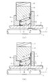
- (A) is the half sectional view of the clutch apparatus which moved the input type rotation member to the axial direction
- (b) is a half sectional view of the clutch apparatus in which a roller is an engagement state.
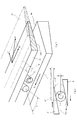
- (A) is a development view of the input raceway surface and the output raceway surface
- (b) is a schematic diagram of the input raceway surface and the output raceway surface in which the rollers are engaged.
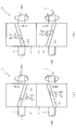
- (A) is a schematic diagram which shows the rotation direction and thrust direction in meshing
- (b) is meshing
- FIG. 1 is an axial sectional view of the clutch device 1 according to the first embodiment of the present invention
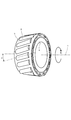
- FIG. 2 is a perspective view of the inner ring 4 (input system rotating member) and the cage 9 showing the arrangement of the rollers 8.
- a mechanism for transmitting power from the inner ring 4 to the outer ring 10 is illustrated, and illustration of a thrust bearing and the like that receives an axial force is omitted. Further, illustration of a part of the teeth 12a, 13a formed on the first gear 12 and the second gear 13 respectively is omitted.
- the clutch device 1 includes an inner ring 4 as an input system rotating member, an outer ring 10 as an output system rotating member arranged on the outer peripheral side of the inner ring 4, and an inner ring 4 and an outer ring 10.
- a plurality of rollers 8 provided, a first gear 12 that rotates together with the outer ring 10, and a second gear 13 that engages with the first gear 12 are mainly provided.
- the inner ring 4 is a member having a function of transmitting the rotational power of the input shaft 2 to the outer ring 10, and an input raceway surface 4a forming a single leaf hyperboloid around the central axis o is formed on the outer peripheral surface.
- the inner ring 4 is restricted from rotating with respect to the input shaft 2 by the spline 4b, and is allowed to move in the axial direction with respect to the input shaft 2.
- the stoppers 5 and 6 are members for restricting the axial movement of the inner ring 4 exceeding a predetermined amount.
- the stoppers 5 and 6 are arranged on the outer periphery of the input shaft 2 at a predetermined interval from the axial end surface of the inner ring 4 and the inner ring 4.
- the inner ring 4 is urged to one axial side (the right side in FIG. 1) by a disc spring 7 disposed between the stopper 5 and the inner ring 4 so that the axial end surface is in contact with the stopper 6.
- the input shaft 2 has a camshaft 3 extending in the axial direction.
- the camshaft 3 is a member for causing the pin 3b to appear and retract on the outer periphery of the input shaft 2 by the cam surface 3a formed on the outer periphery by being moved in the axial direction by a drive device (not shown).
- the pin 3b is a member penetrating in the radial direction of the input shaft 2 and is pushed up by the cam surface 3a so that the tip protrudes from the outer periphery of the input shaft 2 to the inclined surface 4c formed on the inner peripheral surface of the inner ring 4. The tip is pressed.
- the outer ring 10 is a member having a function for transmitting the power of the input shaft 2 to the first gear 12 together with the inner ring 4, and an output raceway surface 10 a forming a single leaf rotation hyperboloid around the central axis o is formed on the inner peripheral surface.
- the outer ring 10 is configured to be rotatable relative to the inner ring 4 and to be relatively movable in the axial direction.
- the outer ring 10 is restricted from moving in the axial direction exceeding a predetermined amount by the flange 5 a and the stopper 6 protruding from the stopper 5.
- the stoppers 5 and 6 stop the axial movement of the inner ring 4 and the outer ring 10 at a fixed position when the roller 8 is engaged and screwed into the input raceway surface 4a and the output raceway surface 10a, and torque exceeding a certain level.
- a torque limiter function that prevents the roller 8 from being removed, and a function of preventing the roller 8 from coming off.
- the outer ring 10 is urged to the other side in the axial direction (left side in FIG. 1) by a disc spring 11 disposed between the stopper 6 and the outer ring 10 so that the end face in the axial direction contacts the flange 5a.
- the disc spring 11 is a member for biasing the outer ring 10 so as to widen the distance between the input raceway surface 4a and the output raceway surface 10a.
- the roller 8 is a member formed in a cylindrical shape, and is held between the input raceway surface 4a and the output raceway surface 10a by the cage 9.
- the cage 9 is a member for holding the rollers 8 at a distance from each other so that the rollers 8 can smoothly rotate without interfering with each other.
- a plurality of the rollers 8 are disposed in the circumferential direction of the input raceway surface 4a and the output raceway surface 10a with a predetermined angle ⁇ (for example, 15 °) from the plane including the central axis o, and the input raceway surface 4a and the output raceway surface 10a.
- the outer peripheral surface is arranged so as to be linearly contactable.
- the first gear 12 is a member for transmitting the power transmitted to the outer ring 10 to the second gear 13 to be engaged.
- the first gear 12 is formed or coupled to the outer peripheral surface of the outer ring 10 integrally with the outer ring 10, and The surface has a plurality of teeth 12a, and the teeth are formed so as to be non-parallel to the central axis o.
- the second gear 13 has a plurality of teeth 13a on the outer peripheral surface, and the tooth lines are formed so as to be non-parallel to the central axis o.
- the first gear 12 and the second gear 13 are formed as a pair of helical gears that engage with each other, and the axis of the rotary shaft 14 of the second gear 13 is arranged at a position different from the central axis o.
- the rotation shaft 14 of the second gear 13 is arranged in parallel with the central axis o.
- the second gear 13 may be a planetary gear mechanism in which a plurality of pinion gears are configured and a ring gear (internal gear) is disposed on the outer periphery of the second gear 13.
- the distance between the stoppers 5 and 6 and the flange 5a is such that the axial end surface of the inner ring 4 abuts against the stopper 6 and the axial end surface of the outer ring 10 abuts against the flange 5a by the biasing force of the disc springs 7 and 11.
- the outer peripheral surface of the roller 8 is set so as not to contact at least one of the input raceway surface 4a and the output raceway surface 10a. In this case, the rollers 8 cannot be engaged with the input raceway surface 4a and the output raceway surface 10a.
- the camshaft 3 is moved to one side in the axial direction (left side in FIG.
- FIGS. 3A is a cross-sectional side view of the clutch device 1 in which the input system rotating member (inner ring 4) is moved in the axial direction
- FIG. 3B is a side view of the clutch device 1 in which the rollers 8 are engaged
- 4A is a developed view of the input raceway surface 4a and the output raceway surface 10a
- FIG. 4B is a view of the input raceway surface 4a and the output raceway surface 10a in which the rollers 8 are engaged.
- It is a schematic diagram.
- the roller 8 and the outer ring 10 rotated by the torque of the inner ring 4 are illustrated by the roller 8 ′ and the outer ring 10 ′ (two-dot chain line).
- the roller 8 and the output raceway surface 10a are displaced (l and L) in the radial direction (up and down direction in FIG. 4B) by the rotation of the roller 8, and the output raceway surface 10a is elastically deformed in the radial direction by the displacement.
- Move in the direction of arrow K see FIG. 4A.
- the outer ring 10 rotates in the direction of the arrow Ro shown in FIG. 4A, and in the direction of the arrow C in the axial direction (the distance between the input track surface 4a and the output track surface 10a (hereinafter referred to as “track interval”)).
- Track interval the distance between the input track surface 4a and the output track surface 10a
- the outer ring 10 narrows the track interval against the biasing force of the disc spring 11 ( Move to the right side of FIG. Thereby, the rollers 8 are engaged with the input raceway surface 4a and the output raceway surface 10a, and the power is transmitted from the inner ring 4 to the outer ring 10.
- the clutch device 1 functions as a torque limiter.
- the inner ring 4 is relatively opposite to the outer ring 10 in the opposite direction (counter arrow Ri direction in FIG. 2).
- the inner ring 4 and the outer ring 10 move relative to each other in the direction away from each other in the axial direction due to a separation force (a force for moving the track interval in the direction of widening) due to the rotation of the roller 8. Since the movement of the inner ring 4 in the axial direction is regulated by the stopper 5 and the pin 3b, the outer ring 10 moves in the direction of increasing the track interval (left side in FIG. 3A) as shown in FIG. .
- the biasing force of the disc spring 11 assists the movement of the outer ring 4 in one axial direction (left side in FIG. 3A). Thereby, the engagement between the input raceway surface 4a and the output raceway surface 10a and the roller 8 is released, and the inner ring 4 and the outer ring 10 can be rotated relative to each other (free rotation).
- FIG. 5A is a schematic diagram showing a rotation direction and a thrust direction in meshing between the first gear 12 and the second gear 13.
- 5A shows the first gear 12 formed on the outer peripheral surface of the outer ring 10 and the second gear 13 engaged therewith, and the illustration of the inner ring 4, the roller 8, etc. is omitted, and the first gear 12 is omitted. Part of the teeth 12a and 13a formed on the first gear 12 and the second gear 13 are not shown.
- Axial forces in a fixed direction are generated in the second gear 13 (driven gear) and the first gear 12, respectively.
- the direction of the tooth traces of the first gear 12 and the second gear 13 is such that the direction of the axial force acting on the first gear 12 (the direction of arrow A in FIG. 5A) is that of the input raceway surface 4a and the output raceway surface 10a. It is set to be the same as the moving direction of the outer ring 10 in the axial direction when narrowing the interval (direction of arrow A in FIG. 5A).
- the axial component of the frictional force generated between the input raceway surface 4a and the output raceway surface 10a and the roller 8 is the inner ring 4 and outer ring 10 when the roller 8 is engaged with the input raceway surface 4a and the output raceway surface 10a.
- the pulling force in the axial direction is suppressed, and a predetermined torque cannot be transmitted from the inner ring 4 to the outer ring 10.
- the outer ring 10 is connected to the input raceway surface by the axial force caused by the reaction force of the second gear 13 in addition to the pulling force of the input raceway surface 4 a and the output raceway surface 10 a due to the rotation of the roller 8.
- Movement in the axial direction is promoted so as to narrow the distance between 4a and the output raceway surface 10a.
- the pulling force in the axial direction of the inner ring 4 and the outer ring 10 can be increased, so that the clutch device 1 can reliably transmit a predetermined torque.
- the friction between the tooth surfaces of the first gear 12 and the second gear 13 will be examined.
- the circumferential force N in the plane perpendicular to the axis is applied to the tooth surface of the first gear 12 by the reaction force of the second gear 13.
- the circumferential force N in the plane perpendicular to the axis also acts on the tooth surface of the second gear 13 that is the driven gear.
- the circumferential force N is decomposed into a tangential force F perpendicular to the central axis o and an axial force S parallel to the central axis o. If the torsion angle of the first gear 12 is ⁇ , the axial force S is expressed by the equation (1).
- the axis of the rotary shaft 14 of the second gear 13 is at a position different from the central axis o. Therefore, the second gear 13 is formed by an internal gear or the like concentric with the first gear 12. Compared to the rotation radius of the second gear 13 can be reduced. As a result, the clutch device 1 can be reduced in size and the structure can be simplified.
- the torque of the outer ring 10 is transmitted by the gears (the first gear 12 and the second gear 13), the torque is transmitted as compared with the case where the torque is transmitted by a ball spline, a pin or the like.
- the area of the contact surface can be increased.
- the surface pressure teeth surface pressure
- the durability of the portion (contact surface) to which torque is transmitted can be improved.
- first gear 12 and the second gear 13 are constituted by helical gears, the strength can be increased as compared with a spur gear of the same size, and the rotational power can be transmitted silently. Further, high-speed rotation can be transmitted, and the combination of the number of teeth of the first gear 12 and the second gear 13 is not limited, and the flexibility is excellent.
- the clutch device 101 inputs power from the second gear 113 to the first gear 112, and uses the outer ring 10 as an input system rotating member and the inner ring 4 as an output system rotating member.
- the first gear 112 (or the second gear 113). Is different from the first embodiment in that the twisting direction of the tooth streaks is different from the twisting direction of the first streaks of the first gear 12 (or the second gear 13) of the clutch device 1 in the first embodiment. .
- symbol is attached
- the present invention is not necessarily limited to this, and the axial end face of the inner ring 4 extends in the axial direction. It is possible to provide an extending portion (not shown) extending outward in the axial direction from the axial end surface of the first gear 12, 112 on the extending portion. By providing the second gears 13 and 113 that are engaged with the first gears 12 and 112, it is possible to achieve the same effects as the present embodiment.
- the case where the input raceway surface 4a and the output raceway surface 10a are formed as a single-leaf rotating hyperboloid and the cylindrical roller 8 is employed has been described.
- the input raceway surface 4a, the output raceway surface 10a, and the rollers 8 it is possible to employ the input raceway surface 4a, the output raceway surface 10a, and the rollers 8.
- the input raceway surface 4a and the output raceway surface 10a are formed as a single-leaf rotating hyperboloid and the roller 8 is conical
- the input raceway surface 4a or the output raceway surface 10a is cylindrical
- first gears 12 and 112 and the second gears 13 and 113 are constituted by a pair of helical gears (oblique gears)
- helical gears oblique gears
- other gears can be adopted as long as the teeth are formed so as to be non-parallel to the axis o and an axial force (thrust) is generated.
- other gears include bevel gears and screw gears.
- the present invention is not limited to this, and the second gears 13 and 113 are internal gears. By doing so, it is naturally possible to provide the axis of the rotation shaft 14 of the second gear 13 or 113 at the same position as the central axis o.
- the rotation shaft 14 of the second gears 13 and 113 is disposed at a position parallel to the central axis o.
- the present invention is not necessarily limited to this, and the positional relationship between the axis of the rotation shaft 14 of the second gears 13 and 113 and the central axis o is appropriately determined depending on the types of the first gears 12 and 112 and the second gears 13 and 113. It is possible to set.
- the axis of the rotation shaft 14 of the second gears 13 and 113 is disposed at a position intersecting the central axis o, and when screw gears are employed, the rotation shafts of the second gears 13 and 113 are arranged. 14 and the central axis o are arranged so as to be a discrepancy axis.
- first gears 12 and 112 are engaged with the second gears 13 and 113 and the rotation shaft 14 of the second gears 13 and 113 is used as the output shaft.
- a planetary gear mechanism is used in which the first gears 12 and 112 are sun gears, the second gears 13 and 113 are constituted by a plurality of pinion gears, and ring gears (internal gears) are arranged outside the second gears 13 and 113.
- ring gears internal gears
- the outer ring 10 is extended in the axial direction to provide first gears 12 and 112 (ring gears), the second gears 13 and 113 are constituted by a plurality of pinion gears, and a sun gear is provided inside the second gears 13 and 113.
- first gears 12 and 112 ring gears
- second gears 13 and 113 are constituted by a plurality of pinion gears
- a sun gear is provided inside the second gears 13 and 113.
- This planetary gear mechanism can adopt either a single pinion type or a double pinion type. In this case, the revolution of the pinion gear can be assigned to the output, and the rotation of the ring gear or sun gear can be assigned to the output.
- the camshaft 3 as a means for moving the inner ring 4 in the axial direction, the pin 3b that protrudes and protrudes by the cam surface 3a of the camshaft 3 and interferes with the inclined surface 4 of the inner ring 4, and the inner ring 4 in the axial direction.
- the present invention is not necessarily limited to this, and other moving means can naturally be employed. Examples of other moving means for moving the inner ring 4 or the outer ring 10 in the axial direction include known means such as a cylinder using fluid pressure and an electromagnet using magnetic force.
- the present invention is not necessarily limited to this, and other urging members are naturally adopted. Is possible. Examples of other urging members include a compression coil spring and a rubber-like elastic body.
- the disc spring 11 that biases the outer ring 10 is provided so as to widen the distance between the input raceway surface 4a and the output raceway surface 10a (moving the outer ring 10 toward the stopper 5).
- the outer ring 10 is moved to the stopper 5 side by the rotation of the roller 8 and the reaction force of the second gear 13, so that the disc spring 11 can be omitted.
Landscapes
- Engineering & Computer Science (AREA)
- General Engineering & Computer Science (AREA)
- Mechanical Engineering (AREA)
- Mechanical Operated Clutches (AREA)
- One-Way And Automatic Clutches, And Combinations Of Different Clutches (AREA)
- Transmission Devices (AREA)
Priority Applications (2)
| Application Number | Priority Date | Filing Date | Title |
|---|---|---|---|
| US14/388,750 US9523398B2 (en) | 2012-03-28 | 2013-03-26 | Clutch device |
| EP13768380.1A EP2833013B1 (de) | 2012-03-28 | 2013-03-26 | Kupplungsvorrichtung |
Applications Claiming Priority (2)
| Application Number | Priority Date | Filing Date | Title |
|---|---|---|---|
| JP2012073099A JP5897951B2 (ja) | 2012-03-28 | 2012-03-28 | クラッチ装置 |
| JP2012-073099 | 2012-03-28 |
Publications (1)
| Publication Number | Publication Date |
|---|---|
| WO2013146776A1 true WO2013146776A1 (ja) | 2013-10-03 |
Family
ID=49260027
Family Applications (1)
| Application Number | Title | Priority Date | Filing Date |
|---|---|---|---|
| PCT/JP2013/058766 Ceased WO2013146776A1 (ja) | 2012-03-28 | 2013-03-26 | クラッチ装置 |
Country Status (4)
| Country | Link |
|---|---|
| US (1) | US9523398B2 (de) |
| EP (1) | EP2833013B1 (de) |
| JP (1) | JP5897951B2 (de) |
| WO (1) | WO2013146776A1 (de) |
Cited By (1)
| Publication number | Priority date | Publication date | Assignee | Title |
|---|---|---|---|---|
| WO2017154133A1 (ja) * | 2016-03-09 | 2017-09-14 | 株式会社ユニバンス | 動力伝達装置 |
Families Citing this family (5)
| Publication number | Priority date | Publication date | Assignee | Title |
|---|---|---|---|---|
| JPWO2018216185A1 (ja) * | 2017-05-26 | 2020-03-26 | 株式会社ユニバンス | 動力伝達装置 |
| US11440181B2 (en) | 2018-11-19 | 2022-09-13 | Abb Schweiz Ag | Planetary gear train, gearbox and industrial robot |
| KR102916509B1 (ko) | 2020-12-31 | 2026-01-22 | 주식회사 카펙발레오 | 컨트롤러블 원웨이클러치 |
| DE102021111056B3 (de) * | 2021-04-29 | 2022-06-23 | Voith Patent Gmbh | Wellenschalter für elektrische Antriebstränge |
| CN113958626B (zh) * | 2021-10-21 | 2023-10-31 | 中国北方车辆研究所 | 一种适用于变速器的单向螺旋联轴器 |
Citations (5)
| Publication number | Priority date | Publication date | Assignee | Title |
|---|---|---|---|---|
| JPH03204418A (ja) * | 1990-01-05 | 1991-09-06 | Shiro Sawa | 流体摩擦伝達力制限装置 |
| JPH03244832A (ja) * | 1990-02-19 | 1991-10-31 | Meihou Koeki Kk | クラッチ軸受 |
| JPH03260422A (ja) * | 1990-03-08 | 1991-11-20 | Kubota Corp | ころがりクラッチ |
| JPH06173976A (ja) | 1992-04-22 | 1994-06-21 | T H K Mento Kenkyusho:Kk | オン−オフクラッチ |
| JPH084792A (ja) * | 1994-06-14 | 1996-01-09 | Thk Ment Kenkyusho:Kk | オンオフ式トルクリミッタ |
Family Cites Families (13)
| Publication number | Priority date | Publication date | Assignee | Title |
|---|---|---|---|---|
| US5211273A (en) * | 1986-01-22 | 1993-05-18 | Hybo Science, Inc. | Axial thrust clutch/bearing/freewheel |
| US5035309A (en) * | 1989-05-08 | 1991-07-30 | Nobuo Takada | Rolling-contact bearing type clutch |
| GB2241755B (en) | 1990-03-08 | 1994-01-12 | Kubota Kk | Conical roller type clutch apparatus |
| JP2938966B2 (ja) * | 1990-11-21 | 1999-08-25 | テイエチケー株式会社 | ころがり軸受クラッチ |
| JPH0893799A (ja) * | 1994-09-29 | 1996-04-09 | Mitsubishi Electric Corp | オーバランニングクラッチ |
| JP3443483B2 (ja) * | 1995-06-12 | 2003-09-02 | 株式会社荏原製作所 | 転がり軸受クラッチ |
| JPH08338503A (ja) * | 1995-06-12 | 1996-12-24 | Ebara Corp | 動力伝達装置 |
| JP3444807B2 (ja) * | 1999-02-12 | 2003-09-08 | 建治 三村 | 差動装置 |
| JP3364603B2 (ja) * | 1999-06-25 | 2003-01-08 | 建治 三村 | 摩擦クラッチ及びこれを用いた自動車の自動変速機及び自動車の無段変速機並びに自動車の動力分配装置及び自動二輪車の動力伝達装置 |
| GB2354814A (en) * | 1999-09-29 | 2001-04-04 | Mechadyne Internat Plc | Phase change mechanism |
| JP2004138125A (ja) * | 2002-10-16 | 2004-05-13 | Ntn Corp | クラッチ |
| WO2005106274A1 (ja) * | 2004-04-30 | 2005-11-10 | Hitachi, Ltd. | 機械式自動変速機のクラッチ構造 |
| DE102008060959A1 (de) * | 2008-12-06 | 2010-06-10 | Neumayer Tekfor Holding Gmbh | Wellenschalter und Getriebe mit zumindest einem Wellenschalter |
-
2012
- 2012-03-28 JP JP2012073099A patent/JP5897951B2/ja not_active Expired - Fee Related
-
2013
- 2013-03-26 WO PCT/JP2013/058766 patent/WO2013146776A1/ja not_active Ceased
- 2013-03-26 EP EP13768380.1A patent/EP2833013B1/de not_active Not-in-force
- 2013-03-26 US US14/388,750 patent/US9523398B2/en not_active Expired - Fee Related
Patent Citations (5)
| Publication number | Priority date | Publication date | Assignee | Title |
|---|---|---|---|---|
| JPH03204418A (ja) * | 1990-01-05 | 1991-09-06 | Shiro Sawa | 流体摩擦伝達力制限装置 |
| JPH03244832A (ja) * | 1990-02-19 | 1991-10-31 | Meihou Koeki Kk | クラッチ軸受 |
| JPH03260422A (ja) * | 1990-03-08 | 1991-11-20 | Kubota Corp | ころがりクラッチ |
| JPH06173976A (ja) | 1992-04-22 | 1994-06-21 | T H K Mento Kenkyusho:Kk | オン−オフクラッチ |
| JPH084792A (ja) * | 1994-06-14 | 1996-01-09 | Thk Ment Kenkyusho:Kk | オンオフ式トルクリミッタ |
Non-Patent Citations (1)
| Title |
|---|
| See also references of EP2833013A4 |
Cited By (1)
| Publication number | Priority date | Publication date | Assignee | Title |
|---|---|---|---|---|
| WO2017154133A1 (ja) * | 2016-03-09 | 2017-09-14 | 株式会社ユニバンス | 動力伝達装置 |
Also Published As
| Publication number | Publication date |
|---|---|
| US9523398B2 (en) | 2016-12-20 |
| JP2013204667A (ja) | 2013-10-07 |
| US20150135874A1 (en) | 2015-05-21 |
| EP2833013A4 (de) | 2015-12-30 |
| EP2833013B1 (de) | 2016-12-28 |
| JP5897951B2 (ja) | 2016-04-06 |
| EP2833013A1 (de) | 2015-02-04 |
Similar Documents
| Publication | Publication Date | Title |
|---|---|---|
| JP5897951B2 (ja) | クラッチ装置 | |
| US8950565B2 (en) | Anti back-drive couplings | |
| CN105899862B (zh) | 具有飞轮和轴向摩擦装置的阀操作器组件 | |
| JP6194436B1 (ja) | 遊星歯車機構を組み合わせた回転伝達装置 | |
| US20140334759A1 (en) | Bearing with Antiskid Design | |
| WO2014034648A1 (ja) | 電動式直動アクチュエータおよび電動式ディスクブレーキ装置 | |
| US20130256083A1 (en) | Driving force transmission apparatus, and four-wheel-drive vehicle including the driving force transmission apparatus | |
| CN104329395A (zh) | 一种双向传动机构 | |
| TW201730450A (zh) | 平板型諧波齒輪裝置 | |
| CN105508545A (zh) | 具组合式传动轴的旋转装置及其组合式传动轴 | |
| TW201537066A (zh) | 齒輪傳動裝置 | |
| JP6082530B2 (ja) | 変速機 | |
| JP2004340367A (ja) | ハイポイドギア装置 | |
| CN105393015B (zh) | 自由型双向离合器 | |
| JP2017054028A5 (de) | ||
| CN105899846B (zh) | 齿轮传动装置 | |
| JP2018071577A (ja) | 減速装置 | |
| WO2012140400A1 (en) | A drive coupling | |
| CN103270336B (zh) | 齿轮传动装置 | |
| CN104179837A (zh) | 单向离合器 | |
| JP4930771B2 (ja) | 電動パワーステアリング装置 | |
| US1036606A (en) | Friction-gearing. | |
| JP6297355B2 (ja) | 逆入力防止クラッチ | |
| US11690736B2 (en) | Anti-back drive device | |
| US10006494B2 (en) | Torque transmission mechanism |
Legal Events
| Date | Code | Title | Description |
|---|---|---|---|
| 121 | Ep: the epo has been informed by wipo that ep was designated in this application |
Ref document number: 13768380 Country of ref document: EP Kind code of ref document: A1 |
|
| NENP | Non-entry into the national phase |
Ref country code: DE |
|
| REEP | Request for entry into the european phase |
Ref document number: 2013768380 Country of ref document: EP |
|
| WWE | Wipo information: entry into national phase |
Ref document number: 2013768380 Country of ref document: EP |
|
| WWE | Wipo information: entry into national phase |
Ref document number: 14388750 Country of ref document: US |