WO2013147258A1 - 耐焼付き性に優れた歯車 - Google Patents
耐焼付き性に優れた歯車 Download PDFInfo
- Publication number
- WO2013147258A1 WO2013147258A1 PCT/JP2013/059737 JP2013059737W WO2013147258A1 WO 2013147258 A1 WO2013147258 A1 WO 2013147258A1 JP 2013059737 W JP2013059737 W JP 2013059737W WO 2013147258 A1 WO2013147258 A1 WO 2013147258A1
- Authority
- WO
- WIPO (PCT)
- Prior art keywords
- less
- gear
- carbide
- nitriding
- surface layer
- Prior art date
- Legal status (The legal status is an assumption and is not a legal conclusion. Google has not performed a legal analysis and makes no representation as to the accuracy of the status listed.)
- Ceased
Links
Images


Classifications
-
- C—CHEMISTRY; METALLURGY
- C21—METALLURGY OF IRON
- C21D—MODIFYING THE PHYSICAL STRUCTURE OF FERROUS METALS; GENERAL DEVICES FOR HEAT TREATMENT OF FERROUS OR NON-FERROUS METALS OR ALLOYS; MAKING METAL MALLEABLE, e.g. BY DECARBURISATION OR TEMPERING
- C21D9/00—Heat treatment, e.g. annealing, hardening, quenching or tempering, adapted for particular articles; Furnaces therefor
- C21D9/32—Heat treatment, e.g. annealing, hardening, quenching or tempering, adapted for particular articles; Furnaces therefor for gear wheels, worm wheels, or the like
-
- C—CHEMISTRY; METALLURGY
- C10—PETROLEUM, GAS OR COKE INDUSTRIES; TECHNICAL GASES CONTAINING CARBON MONOXIDE; FUELS; LUBRICANTS; PEAT
- C10M—LUBRICATING COMPOSITIONS; USE OF CHEMICAL SUBSTANCES EITHER ALONE OR AS LUBRICATING INGREDIENTS IN A LUBRICATING COMPOSITION
- C10M103/00—Lubricating compositions characterised by the base-material being an inorganic material
- C10M103/06—Metal compounds
-
- C—CHEMISTRY; METALLURGY
- C21—METALLURGY OF IRON
- C21D—MODIFYING THE PHYSICAL STRUCTURE OF FERROUS METALS; GENERAL DEVICES FOR HEAT TREATMENT OF FERROUS OR NON-FERROUS METALS OR ALLOYS; MAKING METAL MALLEABLE, e.g. BY DECARBURISATION OR TEMPERING
- C21D1/00—General methods or devices for heat treatment, e.g. annealing, hardening, quenching or tempering
- C21D1/06—Surface hardening
-
- C—CHEMISTRY; METALLURGY
- C21—METALLURGY OF IRON
- C21D—MODIFYING THE PHYSICAL STRUCTURE OF FERROUS METALS; GENERAL DEVICES FOR HEAT TREATMENT OF FERROUS OR NON-FERROUS METALS OR ALLOYS; MAKING METAL MALLEABLE, e.g. BY DECARBURISATION OR TEMPERING
- C21D6/00—Heat treatment of ferrous alloys
- C21D6/002—Heat treatment of ferrous alloys containing Cr
-
- C—CHEMISTRY; METALLURGY
- C21—METALLURGY OF IRON
- C21D—MODIFYING THE PHYSICAL STRUCTURE OF FERROUS METALS; GENERAL DEVICES FOR HEAT TREATMENT OF FERROUS OR NON-FERROUS METALS OR ALLOYS; MAKING METAL MALLEABLE, e.g. BY DECARBURISATION OR TEMPERING
- C21D6/00—Heat treatment of ferrous alloys
- C21D6/004—Heat treatment of ferrous alloys containing Cr and Ni
-
- C—CHEMISTRY; METALLURGY
- C21—METALLURGY OF IRON
- C21D—MODIFYING THE PHYSICAL STRUCTURE OF FERROUS METALS; GENERAL DEVICES FOR HEAT TREATMENT OF FERROUS OR NON-FERROUS METALS OR ALLOYS; MAKING METAL MALLEABLE, e.g. BY DECARBURISATION OR TEMPERING
- C21D6/00—Heat treatment of ferrous alloys
- C21D6/005—Heat treatment of ferrous alloys containing Mn
-
- C—CHEMISTRY; METALLURGY
- C21—METALLURGY OF IRON
- C21D—MODIFYING THE PHYSICAL STRUCTURE OF FERROUS METALS; GENERAL DEVICES FOR HEAT TREATMENT OF FERROUS OR NON-FERROUS METALS OR ALLOYS; MAKING METAL MALLEABLE, e.g. BY DECARBURISATION OR TEMPERING
- C21D6/00—Heat treatment of ferrous alloys
- C21D6/008—Heat treatment of ferrous alloys containing Si
-
- C—CHEMISTRY; METALLURGY
- C21—METALLURGY OF IRON
- C21D—MODIFYING THE PHYSICAL STRUCTURE OF FERROUS METALS; GENERAL DEVICES FOR HEAT TREATMENT OF FERROUS OR NON-FERROUS METALS OR ALLOYS; MAKING METAL MALLEABLE, e.g. BY DECARBURISATION OR TEMPERING
- C21D6/00—Heat treatment of ferrous alloys
- C21D6/02—Hardening by precipitation
-
- C—CHEMISTRY; METALLURGY
- C22—METALLURGY; FERROUS OR NON-FERROUS ALLOYS; TREATMENT OF ALLOYS OR NON-FERROUS METALS
- C22C—ALLOYS
- C22C38/00—Ferrous alloys, e.g. steel alloys
-
- C—CHEMISTRY; METALLURGY
- C22—METALLURGY; FERROUS OR NON-FERROUS ALLOYS; TREATMENT OF ALLOYS OR NON-FERROUS METALS
- C22C—ALLOYS
- C22C38/00—Ferrous alloys, e.g. steel alloys
- C22C38/001—Ferrous alloys, e.g. steel alloys containing N
-
- C—CHEMISTRY; METALLURGY
- C22—METALLURGY; FERROUS OR NON-FERROUS ALLOYS; TREATMENT OF ALLOYS OR NON-FERROUS METALS
- C22C—ALLOYS
- C22C38/00—Ferrous alloys, e.g. steel alloys
- C22C38/002—Ferrous alloys, e.g. steel alloys containing In, Mg, or other elements not provided for in one single group C22C38/001 - C22C38/60
-
- C—CHEMISTRY; METALLURGY
- C22—METALLURGY; FERROUS OR NON-FERROUS ALLOYS; TREATMENT OF ALLOYS OR NON-FERROUS METALS
- C22C—ALLOYS
- C22C38/00—Ferrous alloys, e.g. steel alloys
- C22C38/02—Ferrous alloys, e.g. steel alloys containing silicon
-
- C—CHEMISTRY; METALLURGY
- C22—METALLURGY; FERROUS OR NON-FERROUS ALLOYS; TREATMENT OF ALLOYS OR NON-FERROUS METALS
- C22C—ALLOYS
- C22C38/00—Ferrous alloys, e.g. steel alloys
- C22C38/04—Ferrous alloys, e.g. steel alloys containing manganese
-
- C—CHEMISTRY; METALLURGY
- C22—METALLURGY; FERROUS OR NON-FERROUS ALLOYS; TREATMENT OF ALLOYS OR NON-FERROUS METALS
- C22C—ALLOYS
- C22C38/00—Ferrous alloys, e.g. steel alloys
- C22C38/06—Ferrous alloys, e.g. steel alloys containing aluminium
-
- C—CHEMISTRY; METALLURGY
- C22—METALLURGY; FERROUS OR NON-FERROUS ALLOYS; TREATMENT OF ALLOYS OR NON-FERROUS METALS
- C22C—ALLOYS
- C22C38/00—Ferrous alloys, e.g. steel alloys
- C22C38/18—Ferrous alloys, e.g. steel alloys containing chromium
- C22C38/22—Ferrous alloys, e.g. steel alloys containing chromium with molybdenum or tungsten
-
- C—CHEMISTRY; METALLURGY
- C22—METALLURGY; FERROUS OR NON-FERROUS ALLOYS; TREATMENT OF ALLOYS OR NON-FERROUS METALS
- C22C—ALLOYS
- C22C38/00—Ferrous alloys, e.g. steel alloys
- C22C38/18—Ferrous alloys, e.g. steel alloys containing chromium
- C22C38/24—Ferrous alloys, e.g. steel alloys containing chromium with vanadium
-
- C—CHEMISTRY; METALLURGY
- C22—METALLURGY; FERROUS OR NON-FERROUS ALLOYS; TREATMENT OF ALLOYS OR NON-FERROUS METALS
- C22C—ALLOYS
- C22C38/00—Ferrous alloys, e.g. steel alloys
- C22C38/18—Ferrous alloys, e.g. steel alloys containing chromium
- C22C38/26—Ferrous alloys, e.g. steel alloys containing chromium with niobium or tantalum
-
- C—CHEMISTRY; METALLURGY
- C22—METALLURGY; FERROUS OR NON-FERROUS ALLOYS; TREATMENT OF ALLOYS OR NON-FERROUS METALS
- C22C—ALLOYS
- C22C38/00—Ferrous alloys, e.g. steel alloys
- C22C38/18—Ferrous alloys, e.g. steel alloys containing chromium
- C22C38/28—Ferrous alloys, e.g. steel alloys containing chromium with titanium or zirconium
-
- C—CHEMISTRY; METALLURGY
- C22—METALLURGY; FERROUS OR NON-FERROUS ALLOYS; TREATMENT OF ALLOYS OR NON-FERROUS METALS
- C22C—ALLOYS
- C22C38/00—Ferrous alloys, e.g. steel alloys
- C22C38/18—Ferrous alloys, e.g. steel alloys containing chromium
- C22C38/32—Ferrous alloys, e.g. steel alloys containing chromium with boron
-
- C—CHEMISTRY; METALLURGY
- C22—METALLURGY; FERROUS OR NON-FERROUS ALLOYS; TREATMENT OF ALLOYS OR NON-FERROUS METALS
- C22C—ALLOYS
- C22C38/00—Ferrous alloys, e.g. steel alloys
- C22C38/18—Ferrous alloys, e.g. steel alloys containing chromium
- C22C38/38—Ferrous alloys, e.g. steel alloys containing chromium with more than 1.5% by weight of manganese
-
- C—CHEMISTRY; METALLURGY
- C22—METALLURGY; FERROUS OR NON-FERROUS ALLOYS; TREATMENT OF ALLOYS OR NON-FERROUS METALS
- C22C—ALLOYS
- C22C38/00—Ferrous alloys, e.g. steel alloys
- C22C38/18—Ferrous alloys, e.g. steel alloys containing chromium
- C22C38/40—Ferrous alloys, e.g. steel alloys containing chromium with nickel
- C22C38/42—Ferrous alloys, e.g. steel alloys containing chromium with nickel with copper
-
- C—CHEMISTRY; METALLURGY
- C22—METALLURGY; FERROUS OR NON-FERROUS ALLOYS; TREATMENT OF ALLOYS OR NON-FERROUS METALS
- C22C—ALLOYS
- C22C38/00—Ferrous alloys, e.g. steel alloys
- C22C38/18—Ferrous alloys, e.g. steel alloys containing chromium
- C22C38/40—Ferrous alloys, e.g. steel alloys containing chromium with nickel
- C22C38/58—Ferrous alloys, e.g. steel alloys containing chromium with nickel with more than 1.5% by weight of manganese
-
- C—CHEMISTRY; METALLURGY
- C23—COATING METALLIC MATERIAL; COATING MATERIAL WITH METALLIC MATERIAL; CHEMICAL SURFACE TREATMENT; DIFFUSION TREATMENT OF METALLIC MATERIAL; COATING BY VACUUM EVAPORATION, BY SPUTTERING, BY ION IMPLANTATION OR BY CHEMICAL VAPOUR DEPOSITION, IN GENERAL; INHIBITING CORROSION OF METALLIC MATERIAL OR INCRUSTATION IN GENERAL
- C23C—COATING METALLIC MATERIAL; COATING MATERIAL WITH METALLIC MATERIAL; SURFACE TREATMENT OF METALLIC MATERIAL BY DIFFUSION INTO THE SURFACE, BY CHEMICAL CONVERSION OR SUBSTITUTION; COATING BY VACUUM EVAPORATION, BY SPUTTERING, BY ION IMPLANTATION OR BY CHEMICAL VAPOUR DEPOSITION, IN GENERAL
- C23C8/00—Solid state diffusion of only non-metal elements into metallic material surfaces; Chemical surface treatment of metallic material by reaction of the surface with a reactive gas, leaving reaction products of surface material in the coating, e.g. conversion coatings, passivation of metals
- C23C8/06—Solid state diffusion of only non-metal elements into metallic material surfaces; Chemical surface treatment of metallic material by reaction of the surface with a reactive gas, leaving reaction products of surface material in the coating, e.g. conversion coatings, passivation of metals using gases
- C23C8/08—Solid state diffusion of only non-metal elements into metallic material surfaces; Chemical surface treatment of metallic material by reaction of the surface with a reactive gas, leaving reaction products of surface material in the coating, e.g. conversion coatings, passivation of metals using gases only one element being applied
- C23C8/24—Nitriding
- C23C8/26—Nitriding of ferrous surfaces
-
- C—CHEMISTRY; METALLURGY
- C23—COATING METALLIC MATERIAL; COATING MATERIAL WITH METALLIC MATERIAL; CHEMICAL SURFACE TREATMENT; DIFFUSION TREATMENT OF METALLIC MATERIAL; COATING BY VACUUM EVAPORATION, BY SPUTTERING, BY ION IMPLANTATION OR BY CHEMICAL VAPOUR DEPOSITION, IN GENERAL; INHIBITING CORROSION OF METALLIC MATERIAL OR INCRUSTATION IN GENERAL
- C23C—COATING METALLIC MATERIAL; COATING MATERIAL WITH METALLIC MATERIAL; SURFACE TREATMENT OF METALLIC MATERIAL BY DIFFUSION INTO THE SURFACE, BY CHEMICAL CONVERSION OR SUBSTITUTION; COATING BY VACUUM EVAPORATION, BY SPUTTERING, BY ION IMPLANTATION OR BY CHEMICAL VAPOUR DEPOSITION, IN GENERAL
- C23C8/00—Solid state diffusion of only non-metal elements into metallic material surfaces; Chemical surface treatment of metallic material by reaction of the surface with a reactive gas, leaving reaction products of surface material in the coating, e.g. conversion coatings, passivation of metals
- C23C8/06—Solid state diffusion of only non-metal elements into metallic material surfaces; Chemical surface treatment of metallic material by reaction of the surface with a reactive gas, leaving reaction products of surface material in the coating, e.g. conversion coatings, passivation of metals using gases
- C23C8/34—Solid state diffusion of only non-metal elements into metallic material surfaces; Chemical surface treatment of metallic material by reaction of the surface with a reactive gas, leaving reaction products of surface material in the coating, e.g. conversion coatings, passivation of metals using gases more than one element being applied in more than one step
-
- C—CHEMISTRY; METALLURGY
- C23—COATING METALLIC MATERIAL; COATING MATERIAL WITH METALLIC MATERIAL; CHEMICAL SURFACE TREATMENT; DIFFUSION TREATMENT OF METALLIC MATERIAL; COATING BY VACUUM EVAPORATION, BY SPUTTERING, BY ION IMPLANTATION OR BY CHEMICAL VAPOUR DEPOSITION, IN GENERAL; INHIBITING CORROSION OF METALLIC MATERIAL OR INCRUSTATION IN GENERAL
- C23C—COATING METALLIC MATERIAL; COATING MATERIAL WITH METALLIC MATERIAL; SURFACE TREATMENT OF METALLIC MATERIAL BY DIFFUSION INTO THE SURFACE, BY CHEMICAL CONVERSION OR SUBSTITUTION; COATING BY VACUUM EVAPORATION, BY SPUTTERING, BY ION IMPLANTATION OR BY CHEMICAL VAPOUR DEPOSITION, IN GENERAL
- C23C8/00—Solid state diffusion of only non-metal elements into metallic material surfaces; Chemical surface treatment of metallic material by reaction of the surface with a reactive gas, leaving reaction products of surface material in the coating, e.g. conversion coatings, passivation of metals
- C23C8/80—After-treatment
-
- F—MECHANICAL ENGINEERING; LIGHTING; HEATING; WEAPONS; BLASTING
- F16—ENGINEERING ELEMENTS AND UNITS; GENERAL MEASURES FOR PRODUCING AND MAINTAINING EFFECTIVE FUNCTIONING OF MACHINES OR INSTALLATIONS; THERMAL INSULATION IN GENERAL
- F16H—GEARING
- F16H57/00—General details of gearing
-
- F—MECHANICAL ENGINEERING; LIGHTING; HEATING; WEAPONS; BLASTING
- F16—ENGINEERING ELEMENTS AND UNITS; GENERAL MEASURES FOR PRODUCING AND MAINTAINING EFFECTIVE FUNCTIONING OF MACHINES OR INSTALLATIONS; THERMAL INSULATION IN GENERAL
- F16H—GEARING
- F16H57/00—General details of gearing
- F16H57/04—Features relating to lubrication or cooling or heating
- F16H57/041—Coatings or solid lubricants, e.g. anti-seize layers or pastes
-
- C—CHEMISTRY; METALLURGY
- C21—METALLURGY OF IRON
- C21D—MODIFYING THE PHYSICAL STRUCTURE OF FERROUS METALS; GENERAL DEVICES FOR HEAT TREATMENT OF FERROUS OR NON-FERROUS METALS OR ALLOYS; MAKING METAL MALLEABLE, e.g. BY DECARBURISATION OR TEMPERING
- C21D2211/00—Microstructure comprising significant phases
- C21D2211/001—Austenite
-
- C—CHEMISTRY; METALLURGY
- C21—METALLURGY OF IRON
- C21D—MODIFYING THE PHYSICAL STRUCTURE OF FERROUS METALS; GENERAL DEVICES FOR HEAT TREATMENT OF FERROUS OR NON-FERROUS METALS OR ALLOYS; MAKING METAL MALLEABLE, e.g. BY DECARBURISATION OR TEMPERING
- C21D2211/00—Microstructure comprising significant phases
- C21D2211/002—Bainite
-
- C—CHEMISTRY; METALLURGY
- C21—METALLURGY OF IRON
- C21D—MODIFYING THE PHYSICAL STRUCTURE OF FERROUS METALS; GENERAL DEVICES FOR HEAT TREATMENT OF FERROUS OR NON-FERROUS METALS OR ALLOYS; MAKING METAL MALLEABLE, e.g. BY DECARBURISATION OR TEMPERING
- C21D2211/00—Microstructure comprising significant phases
- C21D2211/004—Dispersions; Precipitations
-
- C—CHEMISTRY; METALLURGY
- C21—METALLURGY OF IRON
- C21D—MODIFYING THE PHYSICAL STRUCTURE OF FERROUS METALS; GENERAL DEVICES FOR HEAT TREATMENT OF FERROUS OR NON-FERROUS METALS OR ALLOYS; MAKING METAL MALLEABLE, e.g. BY DECARBURISATION OR TEMPERING
- C21D2211/00—Microstructure comprising significant phases
- C21D2211/008—Martensite
-
- F—MECHANICAL ENGINEERING; LIGHTING; HEATING; WEAPONS; BLASTING
- F16—ENGINEERING ELEMENTS AND UNITS; GENERAL MEASURES FOR PRODUCING AND MAINTAINING EFFECTIVE FUNCTIONING OF MACHINES OR INSTALLATIONS; THERMAL INSULATION IN GENERAL
- F16H—GEARING
- F16H55/00—Elements with teeth or friction surfaces for conveying motion; Worms, pulleys or sheaves for gearing mechanisms
- F16H55/02—Toothed members; Worms
- F16H55/06—Use of materials; Use of treatments of toothed members or worms to affect their intrinsic material properties
Definitions
- the present invention relates to a gear that is used in an operation site where high rotation and high slip occur and has excellent seizure resistance, and particularly relates to a gear useful for an electric vehicle motor.
- Patent Document 1 C: 0.15 to 0.40%, Si: 0.50 to 1.50%, Mn: 0.20 to 1.50%, Cr: 0.50 to 1.50% And Mo: 0.05 to 0.50%, Ni: 0.50 to 3.50%, Ti: 0.03 to 0.20%, Nb: 0.03 to 0.15%, and Al: containing at least one element selected from the group consisting of 0.01 to 0.10%, P: 0.010% or less, the balance being made of a steel material with Fe and inevitable impurities, A high surface pressure resistant component in which the carbon concentration at the rolling site on the surface of the component is 0.8 to 1.2% is disclosed.
- the carbon concentration is ensured by carburizing or carbonitriding, and no nitriding is performed, so the surface layer nitrogen content is less than 1%. For these reasons, when used in an environment where seizure is more likely to occur, good seizure resistance cannot be ensured.
- Patent Document 2 C: 0.4 to 0.7%, Si: 0.3% or less, Mn: 0.2 to 1%, Cr: 0.2 to 3%, Mo: 0.1 to 1% V: 0.1-1%, Al: 0.01-0.05%, N: 0.003-0.02%, S: 0.07% or less, Ti: 0.002% or less
- the steel is composed of the balance Fe and unavoidable impurities, and P and O in the impurities are suppressed to 0.02% or less and 0.002% or less, respectively, and the material is molded into a predetermined part shape.
- this technology has a process of diffusing surface nitrogen, so the surface nitrogen concentration cannot be kept high, and carbides are not dispersed on the surface of the component, so it exhibits good seizure resistance in a high slip environment. Can not do it.
- Patent Document 3 discloses a method of manufacturing a sewing machine that includes carburizing and tempering case hardening steel such as carbon case hardening steel and chromium molybdenum case hardening steel, and further performing soft nitriding treatment. Has been. However, with this technique, only a normal carburizing process is performed, and carbides are not dispersed on the surface of the component, and good seizure resistance cannot be exhibited in a high slip environment.
- JP 2005-68453 A Japanese Patent Application Laid-Open No. 06-172961 JP 62-211094 A
- the present invention has been made to solve such problems in the prior art, and its purpose is to achieve better seizure resistance in a power transmission section in which lubricating oil with high rotation / slip and low kinematic viscosity is used. It is to provide a gear useful for an electric vehicle motor.
- the gear of the present invention that has solved the above problems is C: 0.15 to 0.45% (meaning “mass%”, the same applies to the chemical composition), Si: 0.05 to 1.0 %, Mn: 1.0 to 2.0%, P: 0.05% or less, S: 0.05% or less, Cr: 0.9 to 2%, Al: 0.01 to 0.1%, and N: each containing 0.02% or less, the balance being made of iron and inevitable impurities, and in the surface layer portion, there is at least one structure of tempered martensite and tempered bainite and residual austenite at an area ratio of 1 to 10%.
- it has a gist in that it has a steel structure in which carbides are precipitated by 5% or more by area ratio, and the nitrogen concentration at a depth of 20 ⁇ m from the surface is 2.0 to 6.0%.
- a nitride layer having an iron nitride concentration of 80% by mass or more exists in the surface layer portion from the surface to a depth of 20 ⁇ m, and the nitride layer is a ratio of Fe 4 N in the iron nitride. Is preferably 20% by mass or more.
- the gear of the present invention includes those having a lubricating film formed on the surface. The gear of the present invention is useful as a gear for an electric vehicle motor.
- the chemical composition is appropriately adjusted, and the structure in the surface layer portion is at least one of tempered martensite and tempered bainite while ensuring a predetermined amount of carbide area ratio and retained austenite, and 20 ⁇ m deep from the surface.
- Nitrogen concentration at 2.0 to 6.0% at this point, so it shows better seizure resistance in power transmission parts where high speed, high slip, low kinematic viscosity lubricating oil is used.
- Such gears are extremely useful for electric vehicle motors.
- the gear excellent in seizure resistance according to the present invention has (i) a nitrogen concentration of 2.0 to 6.0% at a depth of 20 ⁇ m from the gear surface, and (ii) an area ratio of carbide in the surface layer portion of 5%. This is characterized in that (iii) the area ratio of retained austenite in the surface layer portion is 1 to 10%.
- the present inventors examined in detail the seizure generation mechanism in the region where the sliding speed is extremely high. As a result, it has been found that interatomic bonds, that is, adhesive wear due to wear occurring under high temperature, high pressure, and high slip environment are dominant. As a result of further investigation, it is effective to increase the N content (nitrogen concentration) of the gear surface layer part in order to make it difficult to bond between atoms even in an environment where adhesion wear is likely to occur. In addition, it has been found that it is more effective to form a large number of iron nitrides and to appropriately control the composition of iron nitrides than to nitrogen compounds with various additive elements. In addition, it was also effective to disperse carbides in the sliding portion (surface layer) of the component, and it was found that the seizure resistance can be remarkably improved by these synergistic effects, and the present invention was completed.
- controlling the N content (nitrogen concentration) of the surface layer as in (i) above can control N to a thermally more stable iron nitride composition, and the interatomic bond even at the metal contact portion. Can be suppressed. Further, controlling the amount of carbide in the surface layer as in (ii) can suppress adhesive wear in the presence of the chemical stability of the carbide, similarly to the effect of iron nitride.
- the above-mentioned effects cannot be exhibited by any of (i) or (ii) alone, and the seizure resistance can be expressed only by the synergistic effect of (i) and (ii).
- An excellent gear can be realized.
- the amount of retained austenite is defined as described in (iii) above, and by using the processing-induced transformation of retained austenite, it is possible to suppress the generation and propagation of cracks under repeated impact load application. it can. That is, by satisfying the above requirements (i) to (iii), a gear excellent not only in seizure resistance but also in low cycle fatigue characteristics can be obtained. Specific actions and effects by defining these requirements are as follows.
- the carbide present in the surface layer portion also has an action of assisting in concentrating nitrogen in the surface layer portion by nitriding.
- the area ratio of the carbide in the surface layer part needs to be 5% or more.
- the area ratio of the carbide is preferably 6% or more, and more preferably 7% or more.
- Residual austenite can suppress crack initiation and propagation under repeated impact load loading by undergoing processing-induced transformation. For that purpose, it is necessary to make 1% or more of retained austenite exist in steel in an area ratio. However, if the area ratio of retained austenite exceeds 10%, the gear parts are softened and adhesive wear tends to occur.
- the preferable lower limit of the area ratio of retained austenite is 2% or more (more preferably 3% or more), and the preferable upper limit is 9% or less (more preferably 8% or less).
- the structure defined in the present invention is as described above, and the remaining base structure is substantially tempered martensite or tempered bainite, or a composite structure thereof (structure composed of tempered martensite and tempered bainite).
- a structure other than these matrix structures such as ferrite, pearlite, bainitic ferrite, as-quenched martensite, or as-quenched bainite, may be formed in the steel. Since these structures adversely affect the characteristic variation and seizure resistance of the gear, it is desirable that these structures be not generated as much as possible.
- the structure of ferrite, pearlite, bainitic ferrite, as-quenched martensite, as-quenched bainite, etc. is present in an area ratio of 5% or less, it does not adversely affect the operation of the present invention. ,Permissible.
- C is an element necessary for ensuring the hardness of the core as a steel part for machine structural use.
- the C content is less than 0.15%, the core hardness is insufficient, and the strength as a steel part for machine structural use is high. Is lacking.
- the C content is excessive, not only the carbon intrusion amount during carburization is reduced and the amount of precipitated carbide is reduced, but also the core hardness is excessively increased and cold forging workability and machinability are also deteriorated. Therefore, it is necessary to suppress it to 0.45% or less.
- the preferable lower limit of the C content is 0.18% or more (more preferably 0.20% or more), and the preferable upper limit is 0.40% or less (more preferably 0.35% or less).
- Si 0.05 to 1.0%
- Si exhibits the effect of increasing the temper softening resistance and suppressing the decrease in hardness. In order to exhibit such an effect, it is necessary to contain 0.05% or more. However, when the Si content is excessive, the die life at the time of cold forging is reduced and the machinability is also deteriorated.
- the preferable lower limit of the Si content is 0.10% or more (more preferably 0.15% or more), and the preferable upper limit is 0.8% or less (more preferably 0.5% or less).
- Mn has the effects of improving solid solution strengthening and hardenability of the matrix and facilitating the formation of retained austenite. In order to exhibit these effects, it is necessary to contain 1.0% or more. However, if the Mn content is excessive, the concentration of MnO, which is a lower oxide, is increased and the fatigue properties are deteriorated, and the workability and machinability are significantly reduced. .
- a preferable lower limit of the Mn content is 1.1% or more (more preferably 1.2% or more), and a preferable upper limit is 1.8% or less (more preferably 1.7% or less).
- P 0.05% or less
- P segregates at the grain boundaries and shortens the fatigue life, so it is necessary to reduce it as much as possible. In particular, when the content exceeds 0.05%, the fatigue life is significantly reduced. For these reasons, the P content is set to 0.05% or less.
- the P content is preferably 0.045% or less, more preferably 0.040% or less.
- S is an element that forms sulfides. If the content exceeds 0.05%, coarse sulfides are generated, and thus the fatigue life is shortened. Therefore, the S content is 0.05% or less.
- the S content is preferably 0.045% or less, and more preferably 0.040% or less.
- Cr 0.9-2%
- Cr effectively acts to improve strength and improve seizure resistance through improving hardenability and forming stable carbides.
- it is necessary to contain Cr by 0.9% or more.
- the Cr content is excessive, the carbides become coarse and the fatigue characteristics and machinability are deteriorated, so the content needs to be 2% or less.
- a preferable lower limit of the Cr content is 1.1% or more (more preferably 1.2% or more), and a preferable upper limit is 1.9% or less (more preferably 1.8% or less).
- Al 0.01 to 0.1%
- Al is preferably added in an appropriate amount in order to act as a deoxidizer and to reduce the amount of oxide inclusions and enhance the internal quality of the steel material.
- the Al content is set to 0.01% or more.
- the preferable lower limit of the Al content is 0.015% or more (more preferably 0.020% or more), and the preferable upper limit is 0.08% or less (more preferably 0.06% or less).
- N 0.02% or less
- N combines with Al to form AlN and has the effect of refining the crystal grain size.
- the N content is preferably 0.018% or less, and more preferably 0.016% or less.
- the basic components in the gear of the present invention are as described above, and the balance is iron and inevitable impurities (for example, Sb, Mg, etc.).
- the gear of the present invention if necessary, (a) Mo: 0.5% or less (not including 0%), (b) V: 0.2% or less (not including 0%), Ti: 0.0. 1% or less (excluding 0%) and Nb: one or more selected from the group consisting of 0.2% or less (not including 0%), (c) B: 0.01% or less (including 0%) And (d) Cu: 5% or less (not including 0%) and Ni: 5% or less (not including 0%), etc.
- the characteristics of the gear are further improved. The reason for setting a preferable range of these elements is as follows.
- Mo 0.5% or less (excluding 0%)
- Mo is an element effective for improving the impact strength in addition to the effect of significantly improving the hardenability during quenching.
- Mo content is excessive, the material hardness increases and machinability becomes poor.
- it is preferably 0.5% or less. . More preferably, it is 0.45% or less, More preferably, it is 0.40% or less.
- 0.05% or more is preferably contained, more preferably 0.07% or more (more preferably 0.10% or more).
- V 0.2% or less (not including 0%)
- Ti 0.1% or less (not including 0%)
- Nb 0.2% or less (not including 0%)
- V, Ti and Nb are effective elements for improving the seizure resistance by improving the surface hardness of the gear. The detailed effects of these are as follows.
- V improves surface hardness by combining with intrusion N and intrusion C due to soft nitriding to deposit fine V carbon / nitride (carbide, nitride or carbonitride containing V) on the surface layer. And improve seizure resistance.
- V content becomes excessive and exceeds 0.2%, the V charcoal / nitride tends to be coarsened, and the surface hardness is lowered and the fatigue strength is deteriorated. More preferably, it is 0.19% or less, More preferably, it is 0.18% or less.
- the content is preferably 0.05% or more, more preferably 0.06% or more (more preferably 0.07% or more).
- Ti combines with intrusion N and intrusion C due to soft nitriding to improve surface hardness by precipitating fine Ti charcoal / nitride (Ti-containing carbide, nitride or carbonitride) on the surface layer. Improves seizure resistance.
- Ti content becomes excessive and exceeds 0.1%, Ti charcoal / nitride tends to be coarsened, and the surface hardness is lowered and the fatigue strength is deteriorated. More preferably, it is 0.09% or less, More preferably, it is 0.08% or less.
- the content is preferably 0.03% or more, more preferably 0.04% or more (more preferably 0.05% or more).
- Nb combines with intrusion N and intrusion C by soft nitriding to improve surface hardness by precipitating fine Nb carbon / nitride (carbide, nitride or carbonitride containing Nb) on the surface layer. Improves seizure resistance.
- the Nb content becomes excessive and exceeds 0.2%, the Nb charcoal / nitride tends to be coarsened, reducing the surface hardness and deteriorating the fatigue strength. More preferably, it is 0.19% or less, More preferably, it is 0.18% or less.
- it is preferably contained in an amount of 0.05% or more, more preferably 0.06% or more (more preferably 0.07% or more).
- B 0.01% or less (excluding 0%)
- B not only has the effect of significantly improving the hardenability, but is also effective in improving the impact strength.
- the B content is preferably 0.01% or less. More preferably, it is 0.007% or less, More preferably, it is 0.004% or less.
- Cu dissolves in steel and effectively acts to improve the surface layer and internal hardness and to improve seizure resistance. Moreover, it precipitates finely at the time of nitriding, and exhibits the effect
- the Cu content is preferably 5% or less. More preferably, it is 4% or less, More preferably, it is 3% or less.
- Ni has the effect of strengthening the solid solution. Moreover, the Cu precipitation hardening effect
- the gear of the present invention uses the steel material having the chemical composition as described above, and after heat treatment such as annealing as necessary, is processed into a predetermined gear shape, and is subjected to high-concentration carburizing and tempering, Thereafter, nitriding is performed.
- this manufacturing process it is only necessary to adopt a generally used method until it is processed into a gear shape, and the gear processing is also hot forging, cold forging, warm forging, various forging / forging, rolling, Alternatively, it is manufactured by cutting, grinding, or a combination of these methods.
- High-concentration carburizing and quenching is an important process performed for the purpose of precipitation of carbides, and its contents can be divided into a carburization process and a carbide precipitation process.
- a predetermined structure form can be obtained by performing a predetermined high-concentration carburizing and quenching process on the steel material having the above chemical component composition. Tempering is performed from the standpoint of preventing cracking, but it can be omitted if nitriding is performed immediately after quenching. For example, if the tempering process is performed in a temperature range of 100 to 300 ° C. for about 1 to 180 minutes, it is possible to prevent cracking.
- nitriding treatment performed after this is also an important step, and the steel structure having a structure in which carbide is dispersed in the surface layer portion is subjected to nitriding treatment by the above-described chemical composition and high-concentration carburization to obtain a predetermined structure form. And seizure resistance can be improved.
- any known method may be applied, for example, gas nitriding, gas soft nitriding, salt bath nitriding, salt bath carbonitriding, ion nitriding, plasma nitriding, tafflide treatment, gas carbonitriding, etc. Can be mentioned.
- plasma soft nitriding treatment and plasma nitriding treatment are applied as an example of nitriding treatment.
- the plasma soft nitriding is performed by glow discharge in a nitrogen-hydrogen-carbon mixed gas (C mixed gas), and the plasma nitriding is performed by glow discharge in a nitrogen-hydrogen mixed gas.
- Nitriding treatment is performed. When finishing such as machining is required, it may be performed before nitriding, or after nitriding as long as it does not affect the nitrided layer.
- a nitride layer having a concentration of iron nitride (iron nitride) of 80% by mass or more exists in the surface layer portion from the surface to a depth of 20 ⁇ m.
- the ratio of Fe 4 N in iron nitride is preferably 20% by mass or more. Satisfaction resistance is further improved by satisfying these requirements. The reason why such an effect is exhibited can be considered as follows.
- Adhesion wear occurs due to interatomic bonds due to metal contact, but by increasing the proportion of iron nitride, interatomic bonds are less likely to occur and adhesion wear can be suppressed.
- iron nitride generated on the surface layer by nitriding treatment includes Fe 2-3 N, Fe 4 N, and the like, but among them, the one that hardly causes adhesive wear is Fe 4 N.
- the seizure resistance is further improved by increasing the proportion of Fe 4 N.
- the concentration of iron nitride (iron nitride) in the nitride layer is more preferably 85% by mass or more, and still more preferably 90% by mass or more.
- the ratio of Fe 4 N in iron nitride is more preferably 25% by mass or more, and further preferably 30% by mass or more.
- Cr, Al and Mo are elements that are easily combined with nitrogen.
- the diffusion rate of nitrogen decreases and the amount of Fe 2-3 N increases.
- Appropriate amounts of these elements are added (Cr: 1.3% or less, preferably 1.2% or less, Al: 0.040% or less, preferably 0.030% or less, Mo: 0.30% or less, preferably 0 20% or less), the surface layer portion becomes a nitride layer rich in Fe 4 N, and adhesion wear can be prevented (for example, see Test Nos. 28 to 30 in Example 2 described later).
- the nitrogen concentration in the surface layer portion becomes high, and Fe 2 to 3 N is easily formed as compared with the nitriding treatment.
- nitriding is more suitable (see Test Nos. 24 and 25 in Example 2 described later).
- the nitriding temperature about 550 to 630 ° C., preferably about 560 to 600 ° C.
- nitrogen diffuses moderately and the proportion of Fe 4 N increases (test No. 2 in Example 2 described later). 24 and 26).
- Lubricant coating treatment includes, for example, soft metals such as copper, zinc and lead, metal oxides such as lead oxide, sulfides such as molybdenum disulfide and tungsten disulfide, fluorides, nitrides, graphite, manganese phosphate, etc. It is exemplified as a representative one, and general processing types and processing methods are adopted.
- Carburizing conditions (1) Heating temperature (carburizing temperature): 900-980 ° C
- Heating temperature carburizing temperature: 900-980 ° C
- the carburizing temperature is preferably 980 ° C. or lower.
- the holding time (carburizing time) at the carburizing temperature is not particularly limited and may be a time at which a desired carburized layer depth can be obtained, but in the range of 1 hour or more and 10 hours or less in terms of cost. It is better to set as appropriate.
- Cp carbon potential
- the heating atmosphere is preferably controlled so that Cp is 0.9% or more and 1.5% or less. If Cp in this process is too low, the carbon concentration of the steel part surface layer becomes low, and sufficient carbide cannot be precipitated in the next carbide precipitation process, and as a result, it is difficult to ensure desired seizure resistance. It becomes.
- the upper limit of Cp is not particularly limited, but if it is too high, “soot” called “sooting” adheres to the surface of the steel part and inhibits carburization. .
- a more preferable lower limit of Cp is 0.95% or more (more preferably 1.0% or more), and a more preferable upper limit is 1.3% or less (more preferably 1.2% or less).
- the Cp can be measured by a commonly used method such as an O 2 sensor method, a CO 2 method using an infrared analyzer, a dew point measurement method, a carbon potentiometer using an iron wire, etc., but is particularly called a Cp coil.
- the most excellent method in terms of measurement accuracy is to leave the iron wire in the furnace atmosphere and perform quantitative analysis by the infrared absorption method using this Cp coil.
- the upper limit of the average cooling rate is not particularly limited, but it is preferable that the average cooling rate be 4200 ° C./min or less because deformation and cracking are likely to occur in the steel part even if it is cooled too rapidly.
- a more preferable lower limit of this average cooling rate is 13 ° C./min or more (more preferably 15 ° C./min or more), and a more preferable upper limit is 3600 ° C./min or less (more preferably 3000 ° C./min or less).
- Heating temperature 800-860 ° C
- Carbide precipitation is preferably performed within a temperature range of 800 ° C. or higher and 860 ° C. or lower.
- heating temperature exceeds 860 degreeC
- the solid-solution limit of the amount of carbon will become large, and the amount of carbide to precipitate will reduce.
- the heating temperature is less than 800 ° C.
- the precipitated carbide is excessively refined, and the contribution to the improvement of seizure resistance is reduced.
- a more preferable lower limit of the heating temperature is 820 ° C. or higher (more preferably 830 ° C. or higher), and a more preferable upper limit is 855 ° C. or lower (more preferably 850 ° C. or lower).
- Nitriding temperature 350-650 ° C
- a predetermined amount of carbide is precipitated in the nitriding treatment, and the diffusion of N into the steel material is promoted to control the iron nitride composition in which interatomic bonds are less likely to occur. Can be obtained.
- the reason why the lower limit of the processing temperature is set to 350 ° C. is that when the nitriding temperature is too low, the diffusion rate of N is lowered and the processing time is prolonged.
- nitriding temperature in the range of 350 to 650 ° C., various characteristics as a gear part can be satisfied, and excellent seizure resistance can be exhibited even in a high slip environment such as an electric vehicle motor.
- a more preferable lower limit of the nitriding temperature is 400 ° C. or higher (more preferably 450 ° C. or higher), and a more preferable upper limit is 630 ° C. or lower (more preferably 600 ° C. or lower).
- Nitriding time 3 to 30 hours
- the nitriding time (holding time during nitriding) is necessary for diffusing N into the steel and forming iron nitride.
- the amount of diffusion of N and the amount of iron nitride are determined in conjunction with temperature and time, but in the present invention, ranges for obtaining a predetermined structure stably are set by temperature and time, respectively.
- the nitriding time is less than 3 hours, sufficient iron nitride cannot be obtained, and if the temperature is raised too high to achieve the desired structure in less than 3 hours, the matrix matrix becomes soft. There are harmful effects.
- the nitriding time exceeds 30 hours, the matrix matrix becomes soft, and if it is attempted to process at a low temperature in order to prevent this, N does not sufficiently enter the steel, and sufficient iron nitride cannot be generated. There are harmful effects.
- Nitriding atmosphere nitrogen gas concentration 30-80%
- Nitrogen gas concentration (N 2 fraction) in the nitriding atmosphere can obtain excellent seizure resistance by diffusing N into the steel and controlling it to an iron nitride composition in which interatomic bonds are less likely to occur. it can. If the N 2 fraction in the atmosphere is less than 30%, N cannot be sufficiently contained in the steel, and desired gear characteristics cannot be obtained. On the other hand, if the N 2 fraction exceeds 80% and the content of N in the steel is excessively increased, the composition changes again to iron nitride that is easily bonded between atoms, so that the seizure resistance cannot be improved.
- a more preferable lower limit of the N 2 fraction is 35% or more (more preferably 40% or more), and a more preferable upper limit is 75% or less (more preferably 70% or less).
- Example 1 Steel materials with various chemical compositions shown in Tables 1 and 2 below (steel type V is steel equivalent to JIS SCM420) are melted in a small furnace, subjected to solution treatment and normalizing treatment after hot forging, and succeeded. Then, it was roughly processed into the shape of a roller pitching test piece having a diameter of 26 mm ⁇ length of 130 mm by machining. The test pieces after roughing were subjected to high-concentration carburizing treatment (carburizing and carbide precipitation treatment) with various patterns shown in FIG. 1 [FIGS. 1 (a) to (f)].
- high-concentration carburization was performed by leaving it in a high carbon potential (Cp) atmosphere in the first stage, and fine carbides were deposited on the carburized portion of the surface layer by reheating in the second stage.
- the average cooling rate after high concentration carburization was set to 50 ° C./second.
- a tempering process was performed, and a plasma soft nitriding process (hereinafter sometimes simply referred to as “nitriding process”) was performed to form a structure containing nitrogen at a high concentration in the surface layer portion.
- finishing was performed to obtain a test piece.
- FIG. 2 shows the shape (after finishing) of the roller pitching test piece.
- the area ratio of carbide in the structure (the main structure is at least one structure of tempered martensite and tempered bainite) is obtained by cutting a specimen after nitriding treatment in a cross section, embedding it in a resin, mirror polishing, and using an etched sample. A position 20 ⁇ m deep from the surface was measured using a scanning electron microscope (SEM). When high-concentration carburizing is performed, carbon diffuses from the surface layer toward the inside. As a result, a concentrated carbon layer is formed from the surface layer portion toward the inside, and a carbide is also formed accordingly.
- SEM scanning electron microscope
- the carbide in the vicinity of the surface is important, and the carbide in the vicinity of the surface needs to be 5% or more by area ratio.
- the carbide near the surface since it is difficult to directly measure the carbide near the surface, here, the carbide at a depth of 20 ⁇ m from the surface, which has almost the same area ratio as the vicinity of the surface, is defined as the carbide near the surface. Is 5% or more.
- An arbitrary visual field of 9 ⁇ m ⁇ 12 ⁇ m was observed at a magnification of 8000 times, and the carbide portion was identified by image analysis software, and the area ratio was determined. At this time, the measurement was performed for three fields of view, and the arithmetic average of these three fields of view was defined as the area ratio of the carbide.
- the nitrogen concentration in the surface layer part was measured by cutting the test piece in a cross section, embedding it in a resin, mirror polishing, and then measuring the nitrogen concentration from the surface layer part to the inside using an electron beam microprobe analyzer ( It was measured by analysis using an Electron Probe Microanalyzer (EPMA).
- EPMA Electron Probe Microanalyzer
- Part characteristics evaluation method As an evaluation method for component characteristics, a roller pitching test was performed. The roller pitching test was performed by a roller pitching tester using the test piece (small roller) and a large roller (counter material) made of high carbon chromium bearing steel SUJ2. The test conditions were as follows: rotational speed: 1000 rpm, relative slip ratio: 700%, oil temperature: 90 ° C., and the number of revolutions until the test apparatus stopped due to vibration caused by the occurrence of seizure was determined. At this time, 20000 ⁇ 10 3 times was set as the upper limit, and the seizure generation life was assumed. Those having no seizure up to 10,000 ⁇ 10 3 times were evaluated as having excellent seizure resistance.
- Test No. No. 18 has a nitrogen gas concentration (N 2 fraction) at the time of nitriding treatment that is too high, so that nitrogen is excessively concentrated in the surface layer portion and seizure resistance is deteriorated.
- Test No. No. 19 has a low carbon potential (Cp) at the time of carburization [heat treatment pattern FIG. 1 (d)], the carbide area ratio cannot be secured, and seizure resistance is deteriorated.
- Test No. No. 20 uses a steel type with a low Cr content (steel type S), and even if the manufacturing conditions are appropriate, the carbide area ratio cannot be ensured and seizure resistance is deteriorated.
- Test No. No. 21 uses a steel type with excessive C content (steel type T), and the amount of carbon intrusion during carburization is insufficient, so that the carbide area ratio cannot be secured, and the nitrogen concentration in the surface layer is also low. Adhesiveness has deteriorated.
- Test No. No. 23 is a JIS SCM420 equivalent steel that has been subjected to a lubrication film treatment after carburizing, but since it has not been subjected to high-concentration carburizing or nitriding treatment [Heat Treatment Pattern 1 (f)], the carbide area ratio can be secured. In addition, since the nitrogen concentration in the surface layer is reduced and the amount of residual ⁇ is also large, the seizure resistance is extremely deteriorated.
- Example 2 The steel materials (steel types B, W, X, and Y: steel type B is the same as steel type B shown in Table 1) are melted in a small furnace and hot forged. Thereafter, a solution treatment and a normalizing treatment were carried out, succeeded, and roughly machined into a shape of a roller pitching test piece having a diameter of 26 mm ⁇ a length of 130 mm by machining. The test piece after roughing was subjected to high-concentration carburizing treatment (carburizing and carbide precipitation treatment) with the heat treatment pattern shown in FIG. At this time, the average cooling rate after high concentration carburization was set to 50 ° C./second.
- high-concentration carburizing treatment carburizing and carbide precipitation treatment
- nitriding treatment plasma soft nitriding treatment or plasma nitriding treatment
- tempering treatment was performed, and nitriding treatment (plasma soft nitriding treatment or plasma nitriding treatment) was carried out to form a structure containing nitrogen at a high concentration in the surface layer portion.
- nitriding treatment finishing was performed to obtain a test piece.
- a roller pitching test was conducted in the same manner as in Example 1.
- nitriding treatment conditions heating temperature, holding time, and gas fraction (N 2 , H 2 , C gas mixture fraction) are shown in Table 8 below (Test Nos. 24 to 30).
- each structure area ratio of carbide, residual ⁇ area ratio
- nitrogen concentration surface layer nitrogen concentration
- component characteristics surface characteristics
- the ratio of iron nitride in the surface layer is the total relative of Fe 4 N and Fe 2 to 3 N with respect to the total relative concentration (100% by mass) of all the components present in the surface layer of the specimen, which was confirmed as a result of X-ray diffraction. is the concentration ratio (mass%), the proportion of Fe 4 the ratio of the N, Fe 4 N relative concentrations to the total relative concentration of Fe 4 N and Fe 2 ⁇ 3 N of nitride in the iron (wt%) The value is calculated by the following formula.
- All components present on the surface layer of the specimen are Fe 4 N, Fe 2 to 3 N, Fe 5 C 2 , Fe 3 C, ⁇ -Fe, ⁇ -Fe, etc.
- the total ratio is 100%, but other components (for example, Fe 2 C, Fe 22 C, Fe 7 C 3 etc.) may be contained in a small amount (5% or less). The total of these components is 100%).
- the chemical composition of the steel material and the production conditions are both controlled within an appropriate range, so that all of the carbide area ratio, residual ⁇ area ratio, and surface layer nitrogen concentration are It can control within the range prescribed
- the adhesion suppressing effect is excellent and excellent seizure resistance can be exhibited.
- test no. 25 to 27, 29, and 30 satisfy the preferable requirements for the composition of the nitride layer, and it can be seen that particularly excellent seizure resistance is obtained.
- the gear of the present invention has a predetermined chemical composition, and in the surface layer portion, at least one structure of tempered martensite and tempered bainite, retained austenite at an area ratio of 1 to 10%, and carbide has an area ratio.
- the steel structure is 5% or more precipitated and the nitrogen concentration at a depth of 20 ⁇ m from the surface is 2.0 to 6.0%, so that high rotation / slip and low kinematic viscosity are achieved.
- the power transmission section where lubricating oil is used, it exhibits better seizure resistance.
Landscapes
- Chemical & Material Sciences (AREA)
- Engineering & Computer Science (AREA)
- Mechanical Engineering (AREA)
- Organic Chemistry (AREA)
- Materials Engineering (AREA)
- Metallurgy (AREA)
- Thermal Sciences (AREA)
- Physics & Mathematics (AREA)
- Crystallography & Structural Chemistry (AREA)
- Chemical Kinetics & Catalysis (AREA)
- General Engineering & Computer Science (AREA)
- General Chemical & Material Sciences (AREA)
- Oil, Petroleum & Natural Gas (AREA)
- Heat Treatment Of Articles (AREA)
- Solid-Phase Diffusion Into Metallic Material Surfaces (AREA)
- Gears, Cams (AREA)
Description
本発明は、高回転・高すべりの発生する作動部位において使用され、優れた耐焼付き性を有する歯車に関するものであり、特に電気自動車モータ用として有用な歯車に関するものである。
例えば、自動車のトランスミッション用歯車などのような動力伝達部に使用される機械構造部品は、その使用時に、接触面圧の増大によって金属接触部分が剥離損傷するピッチング損傷を起こすことが知られている。そこで、このような用途に使用される鋼部品としては、SCr、SCM、SNCM等の各種肌焼鋼を用いて、熱間鍛造や切削加工で成形加工した後、浸炭処理や浸炭窒化処理等の表面硬化処理を施し、更に必要によっては、部品表面に二硫化モリブデンなどの固体潤滑皮膜を形成したものが用いられている。
しかしながら、近年では、機械構造部の高出力化、小型軽量化に対する要求が高まっており、これら動力伝達部に使用される機械構造部品にかかる負荷はますます増大する傾向にある。そのため、SCr、SCM、SNCM等の各種肌焼鋼を表面硬化処理した部品のみならず、固体潤滑皮膜を形成させたとしても、要求される耐ピッチング性を達成することが困難になりつつある。
ところで、近年の環境負荷低減から生産量が拡大しつつある電気自動車においては、モータの回転を減速ギアに直接伝達するため、ガソリン車よりもこれらの部品が高回転下に曝されることになる。また、使用環境における動粘度がガソリン車よりも低い潤滑油が使用されるため、これら動力伝達部を構成する鋼部品の表面に形成される油膜が薄く、場合によっては油膜がほとんど形成されない箇所も局所的に発生する環境下にある。特に、高回転・高すべりとなるに伴い、油温も上昇し、潤滑油の動粘度が低下しやすくなり、ますます油膜切れが発生する部位が増える。そのため、これらの環境下では、鋼部品同士の金属接触による摩耗が生じやすく、また摩擦熱による温度上昇が生じて鋼部品の軟化も生じやすいため、焼付きが早期に発生し易いという問題がある。
上記のような環境下で使用される鋼部材に関連する技術は、これまでにも種々提案されている。例えば、特許文献1では、C:0.15~0.40%、Si:0.50~1.50%、Mn:0.20~1.50%、Cr:0.50~1.50%、およびMo:0.05~0.50%を含有し、Ni:0.50~3.50%、Ti:0.03~0.20%、Nb:0.03~0.15%、およびAl:0.01~0.10%から成る群より選ばれた少なくとも1種以上の元素を含有し、P:0.010%以下であり、残部がFeおよび不可避不純物である鋼材から成り、この部品表面における転動部位の炭素濃度が0.8~1.2%である耐高面圧部品が開示されている。
しかしながらこの技術では、浸炭または浸炭窒化処理で炭素濃度を確保しており、窒化処理がなされていないため、表層窒素量は1%にも満たないものである。こうしたことから、より焼付きが発生しやすい環境で使用されると、良好な耐焼付き性が確保できない。
特許文献2では、C:0.4~0.7%、Si:0.3%以下、Mn:0.2~1%、Cr:0.2~3%、Mo:0.1~1%、V:0.1~1%、Al:0.01~0.05%、N:0.003~0.02%、S:0.07%以下、Ti:0.002%以下を夫々含有し、残部Feおよび不可避不純物からなり、該不純物中のPおよびOを夫々0.02%以下、0.002%以下に抑えてなる鋼を素材とし、該素材を所定の部品形状に成形した後、窒化処理または軟窒化処理を行い、引き続き高周波焼入れ処理を行うことによって、表面から窒素を拡散させ、最表面から少なくとも0.2mmの深さ位置において窒素濃度を0.05%以上含有させた表面硬化層を形成することを特徴とする疲労強度特に面疲労強度に優れた機械構造用部品の製造方法が開示されている。
しかしながらこの技術では、表面窒素を拡散させる処理があるため、表層窒素濃度を高く維持することができず、また部品表層に炭化物も分散していないため、高滑り環境で良好な耐焼付き性を発揮することができない。
一方、特許文献3には、炭素肌焼鋼やクロムモリブデン肌焼鋼等の肌焼鋼に浸炭焼入れ、焼戻しを行い、更に軟窒化処理を施すことを特徴とするミシンのかまの製造方法が開示されている。しかしながらこの技術では、通常の浸炭処理が行われているのみであり、部品表層に炭化物が分散存在しておらず、高滑り環境で良好な耐焼付き性を発揮することができない。
本発明はこうした従来技術における課題を解決する為になされたものであって、その目的は、高回転・高すべり、低い動粘度の潤滑油が使用される動力伝達部において、より優れた耐焼付き性を発揮し、電気自動車モータ用として有用な歯車を提供することにある。
上記課題を解決することのできた本発明の歯車とは、C:0.15~0.45%(「質量%」の意味、化学成分組成について以下同じ)、Si:0.05~1.0%、Mn:1.0~2.0%、P:0.05%以下、S:0.05%以下、Cr:0.9~2%、Al:0.01~0.1%、およびN:0.02%以下を夫々含有し、残部が鉄および不可避不純物からなり、表層部において、焼戻しマルテンサイトおよび焼戻しベイナイトの少なくとも一方の組織と、面積率1~10%で残留オーステナイトが存在すると共に、炭化物が面積率で5%以上析出している鋼材組織を有し、且つ表面から20μm深さにおける窒素濃度が2.0~6.0%である点に要旨を有するものである。
本発明の歯車においては、必要によって更に(a)Mo:0.5%以下(0%を含まない)、(b)V:0.2%以下(0%を含まない)、Ti:0.1%以下(0%を含まない)およびNb:0.2%以下(0%を含まない)よりなる群から選ばれる1種以上、(c)B:0.01%以下(0%を含まない)、(d)Cu:5%以下(0%を含まない)およびNi:5%以下(0%を含まない)よりなる群から選ばれる1種以上、等を含有させることも有効であり、含有される成分に応じて歯車の特性が更に改善される。
本発明の歯車においては、表面から20μm深さまでの表層部において、窒化鉄の濃度が80質量%以上である窒化層が存在しており、当該窒化層は、窒化鉄中のFe4Nの割合が20質量%以上であることも好ましい要件である。また本発明の歯車には、表面に潤滑皮膜が形成されたものも包含する。本発明の歯車は、電気自動車モータ用の歯車として有用である。
本発明では、化学成分組成を適切に調整すると共に、表層部における組織を、炭化物面積率および残留オーステナイトを所定量確保しつつ焼戻しマルテンサイトおよび焼戻しベイナイトの少なくとも一方の組織とし、且つ表面から20μm深さにおける窒素濃度を2.0~6.0%となるようにしたので、高回転・高すべり、低い動粘度の潤滑油が使用される動力伝達部において、より優れた耐焼付き性を発揮し、このような歯車は電気自動車モータ用として極めて有用である。
本発明の耐焼付き性に優れた歯車は、(i)歯車表面から20μm深さにおける窒素濃度が2.0~6.0%であること、(ii)表層部における炭化物の面積率が5%以上であること、(iii)表層部における残留オーステナイトの面積率が1~10%であること、等を特徴としている。
主としてガソリン車を対象として発生するピッチング損傷は、油膜切れによる歯車間の金属同士の接触によって摩擦熱が発生し、歯車が熱軟化することによる考えられてきた。そして、耐ピッチング性に優れる歯車部品を実現するには、部品そのものの表面、内部強度、或は焼戻し軟化抵抗の向上が有効であり、高強度化によって耐ピッチング性が改善されてきた。しかしながら、電気自動車モータ用歯車では、従来のガソリン車と比較して、歯面間のすべり速度が数倍以上になり、損傷メカニズムが焼付きへと変化するため、部品そのものの表面、内部強度、或は焼戻し軟化抵抗を向上させることの延長線上では耐焼付き性の改善指針を見出すことができない。
本発明者らは、すべり速度が極めて高い領域での焼付き発生メカニズムを詳細に検討した。その結果、高温・高圧・高すべり環境下で摩耗が生じることによる原子間結合、即ち凝着摩耗が支配的であることが判明した。そして、更に検討を進めた結果、凝着摩耗が発生しやすい環境下においても原子間結合しにくくなるようにするためには、歯車表層部のN含有量(窒素濃度)を高めることが有効であり、また各種添加元素との窒素化合物よりも、鉄窒化物を多数形成させると共に、鉄窒化物の組成を適切に制御することが有効であることを見出した。加えて、部品の摺動部(表層)に炭化物を分散させることも有効であり、これらの相乗効果によって、耐焼付き性を著しく向上させることができることを見出し、本発明を完成した。
本発明における耐焼付き性改善の推定メカニズムは、次のように考えられる。即ち、上記(i)のように表層部のN含有量(窒素濃度)を制御することは、Nを熱的により安定な鉄窒化物組成に制御することができ、金属接触部分でも原子間結合を抑制することができる。また(ii)のように表層部の炭化物量を制御することは、鉄窒化物の効果と同様に、炭化物の化学的安定性によって、その存在で凝着摩耗を抑制することができる。
但し、上記の効果は、(i)または(ii)のいずれか単独では耐焼付き性の著しい向上を発現させることができず、(i)および(ii)の相乗効果によって初めて、耐焼付き性に優れた歯車を実現することができる。また本発明では、上述の(iii)のように、残留オーステナイト量を規定しており、残留オーステナイトの加工誘起変態を利用することによって、繰り返し衝撃荷重負荷時の亀裂発生および進展を抑制することができる。即ち、上記(i)~(iii)の要件を満たすことによって、耐焼付き性のみならず、低サイクル疲労特性にも優れた歯車を得ることができる。これらの要件を規定したことによる具体的な作用効果は下記の通りである。
[(i)の要件]
歯車としての耐焼付き性を改善するためには、表面から20μm深さ位置での窒素濃度を2.0~6.0%となるように制御する必要がある。この部分における窒素濃度が、2.0%未満になると、金属接触による原子間結合が発生しやすくなり、凝着摩耗が生じることになる。一方、窒素濃度が6.0%を超えると、表層近傍の窒化物の原子構造が変化してしまうため、却って凝着摩耗が生じやすくなる。この窒素濃度の好ましい下限は3.2%以上(より好ましくは3.5%以上)であり、好ましい上限は5.8%以下(より好ましくは5.5%以下)である。
歯車としての耐焼付き性を改善するためには、表面から20μm深さ位置での窒素濃度を2.0~6.0%となるように制御する必要がある。この部分における窒素濃度が、2.0%未満になると、金属接触による原子間結合が発生しやすくなり、凝着摩耗が生じることになる。一方、窒素濃度が6.0%を超えると、表層近傍の窒化物の原子構造が変化してしまうため、却って凝着摩耗が生じやすくなる。この窒素濃度の好ましい下限は3.2%以上(より好ましくは3.5%以上)であり、好ましい上限は5.8%以下(より好ましくは5.5%以下)である。
[(ii)の要件]
歯車表層部に炭化物を多数析出させることで、高すべり環境下において、耐焼付き性を向上させることができる。また表層部に存在する炭化物は、窒化によって表層部に窒素を著しく濃化させることを援助する作用も有する。そのためには、表層部での炭化物の面積率は5%以上である必要がある。炭化物の面積率が5%に満たない場合には、表層部近傍での窒素の濃化が不十分になるだけでなく、炭化物自身による耐焼付き性改善効果も不足するため、所定の耐焼付き性を得られない。この炭化物の面積率は好ましくは6%以上であり、より好ましくは7%以上である。
歯車表層部に炭化物を多数析出させることで、高すべり環境下において、耐焼付き性を向上させることができる。また表層部に存在する炭化物は、窒化によって表層部に窒素を著しく濃化させることを援助する作用も有する。そのためには、表層部での炭化物の面積率は5%以上である必要がある。炭化物の面積率が5%に満たない場合には、表層部近傍での窒素の濃化が不十分になるだけでなく、炭化物自身による耐焼付き性改善効果も不足するため、所定の耐焼付き性を得られない。この炭化物の面積率は好ましくは6%以上であり、より好ましくは7%以上である。
[(iii)の要件]
残留オーステナイトは、加工誘起変態することで、繰り返し衝撃荷重負荷時の亀裂発生および進展を抑制することができる。そのためには鋼中に、面積率で1%以上の残留オーステナイトを存在させることが必要である。しかしながら、残留オーステナイトの面積率が10%を超えて存在すると、歯車部品を軟化させて、凝着摩耗が生じやすくなる。残留オーステナイトの面積率の好ましい下限は2%以上(より好ましくは3%以上)であり、好ましい上限は9%以下(より好ましくは8%以下)である。
残留オーステナイトは、加工誘起変態することで、繰り返し衝撃荷重負荷時の亀裂発生および進展を抑制することができる。そのためには鋼中に、面積率で1%以上の残留オーステナイトを存在させることが必要である。しかしながら、残留オーステナイトの面積率が10%を超えて存在すると、歯車部品を軟化させて、凝着摩耗が生じやすくなる。残留オーステナイトの面積率の好ましい下限は2%以上(より好ましくは3%以上)であり、好ましい上限は9%以下(より好ましくは8%以下)である。
本発明で規定する組織は上記の通りであって、残部となる基地組織は実質的に焼戻しマルテンサイトまたは焼戻しベイナイト、或はそれらの複合組織(焼戻しマルテンサイトおよび焼戻しベイナイトからなる組織)である。しかし、窒化処理後には、鋼中にこれら基地組織以外の組織、例えばフェライトやパーライト、ベイニティックフェライト、焼入れままマルテンサイト、焼入れままベイナイト等の組織が形成される場合がある。これらの組織は、歯車の特性バラつき、耐焼付き性に悪影響を及ぼすため、極力生成しないことが望まれる。但し、フェライトやパーライト、ベイニティックフェライト、焼入れままマルテンサイト、焼入れままベイナイト等の組織が、面積率で5%以下の割合で存在する場合に限って、本発明の作用に悪影響を与えないため、許容される。
本発明の歯車においては、最終製品(歯車部品)としての特性を発揮させるために、その化学成分組成をも適切に調整する必要がある。その化学成分組成における各成分(元素)の範囲限定理由は次の通りである。
[C:0.15~0.45%]
Cは、機械構造用鋼部品としての芯部硬さを確保するのに必要な元素であり、C含有量が0.15%未満では芯部硬さが不足し、機械構造用鋼部品として強度が不足する。しかしながら、C含有量が過剰になると、浸炭時の炭素浸入量が減って炭化物の析出量が少なくなるだけでなく、芯部硬さが過度に高くなって冷鍛加工性や被削性も劣化するので、0.45%以下に抑える必要がある。C含有量の好ましい下限は0.18%以上(より好ましくは0.20%以上)であり、好ましい上限は0.40%以下(より好ましくは0.35%以下)である。
Cは、機械構造用鋼部品としての芯部硬さを確保するのに必要な元素であり、C含有量が0.15%未満では芯部硬さが不足し、機械構造用鋼部品として強度が不足する。しかしながら、C含有量が過剰になると、浸炭時の炭素浸入量が減って炭化物の析出量が少なくなるだけでなく、芯部硬さが過度に高くなって冷鍛加工性や被削性も劣化するので、0.45%以下に抑える必要がある。C含有量の好ましい下限は0.18%以上(より好ましくは0.20%以上)であり、好ましい上限は0.40%以下(より好ましくは0.35%以下)である。
[Si:0.05~1.0%]
Siは、焼戻し軟化抵抗を高めて硬さの低下を抑制する効果を発揮する。こうした効果を発揮させるためには、0.05%以上含有させる必要がある。しかしながら、Si含有量が過剰になると、冷間鍛造時の金型寿命を低下させるとともに、被削性も劣化させるため、1.0%以下とする必要がある。Si含有量の好ましい下限は0.10%以上(より好ましくは0.15%以上)であり、好ましい上限は0.8%以下(より好ましくは0.5%以下)である。
Siは、焼戻し軟化抵抗を高めて硬さの低下を抑制する効果を発揮する。こうした効果を発揮させるためには、0.05%以上含有させる必要がある。しかしながら、Si含有量が過剰になると、冷間鍛造時の金型寿命を低下させるとともに、被削性も劣化させるため、1.0%以下とする必要がある。Si含有量の好ましい下限は0.10%以上(より好ましくは0.15%以上)であり、好ましい上限は0.8%以下(より好ましくは0.5%以下)である。
[Mn:1.0~2.0%]
Mnは、マトリクスの固溶強化および焼入れ性を向上させると共に、残留オーステナイトを生成させ易くする効果がある。これらの効果を発揮させるためには、1.0%以上含有させる必要がある。しかしながら、Mn含有量が過剰になると、低級酸化物であるMnO濃度が上昇し、疲労特性を悪化させる他、加工性や被削性が著しく低下するので、2.0%以下とする必要がある。Mn含有量の好ましい下限は1.1%以上(より好ましくは1.2%以上)であり、好ましい上限は1.8%以下(より好ましくは1.7%以下)である。
Mnは、マトリクスの固溶強化および焼入れ性を向上させると共に、残留オーステナイトを生成させ易くする効果がある。これらの効果を発揮させるためには、1.0%以上含有させる必要がある。しかしながら、Mn含有量が過剰になると、低級酸化物であるMnO濃度が上昇し、疲労特性を悪化させる他、加工性や被削性が著しく低下するので、2.0%以下とする必要がある。Mn含有量の好ましい下限は1.1%以上(より好ましくは1.2%以上)であり、好ましい上限は1.8%以下(より好ましくは1.7%以下)である。
[P:0.05%以下]
Pは、結晶粒界に偏析して疲労寿命を短くするのでできるだけ低減する必要がある。特に、その含有量が0.05%を超えると、疲労寿命の低下が著しくなる。こうしたことから、P含有量は0.05%以下とした。P含有量は好ましくは0.045%以下であり、より好ましくは0.040%以下である。
Pは、結晶粒界に偏析して疲労寿命を短くするのでできるだけ低減する必要がある。特に、その含有量が0.05%を超えると、疲労寿命の低下が著しくなる。こうしたことから、P含有量は0.05%以下とした。P含有量は好ましくは0.045%以下であり、より好ましくは0.040%以下である。
[S:0.05%以下]
Sは、硫化物を形成する元素であり、その含有量が0.05%を超えると、粗大な硫化物が生成するため疲労寿命を短くする。従って、Sの含有量は0.05%以下とする。S含有量は好ましくは0.045%以下であり、より好ましくは0.040%以下である。
Sは、硫化物を形成する元素であり、その含有量が0.05%を超えると、粗大な硫化物が生成するため疲労寿命を短くする。従って、Sの含有量は0.05%以下とする。S含有量は好ましくは0.045%以下であり、より好ましくは0.040%以下である。
[Cr:0.9~2%]
Crは、焼入れ性の向上と安定な炭化物の形成を通じて、強度の向上および耐焼付き性を向上させるのに有効に作用する。こうした効果を発揮させるためには、Crは0.9%以上含有させる必要がある。しかしながら、Crの含有量が過剰になると、炭化物が粗大化し、疲労特性および切削性を低下させるため、その含有量は2%以下とする必要がある。Cr含有量の好ましい下限は1.1%以上(より好ましくは1.2%以上)であり、好ましい上限は1.9%以下(より好ましくは1.8%以下)である。
Crは、焼入れ性の向上と安定な炭化物の形成を通じて、強度の向上および耐焼付き性を向上させるのに有効に作用する。こうした効果を発揮させるためには、Crは0.9%以上含有させる必要がある。しかしながら、Crの含有量が過剰になると、炭化物が粗大化し、疲労特性および切削性を低下させるため、その含有量は2%以下とする必要がある。Cr含有量の好ましい下限は1.1%以上(より好ましくは1.2%以上)であり、好ましい上限は1.9%以下(より好ましくは1.8%以下)である。
[Al:0.01~0.1%]
Alは、脱酸剤として作用し、酸化物系介在物量を低減して鋼材の内部品質を高める作用を発揮するため適量添加することが好ましい。こうした観点から、Al含有量は0.01%以上とした。しかしながら、Al含有量が過剰になると、粗大で硬い介在物(Al2O3)が生成し、疲労特性を低下させるので0.1%以下とする必要がある。Al含有量の好ましい下限は0.015%以上(より好ましくは0.020%以上)であり、好ましい上限は0.08%以下(より好ましくは0.06%以下)である。
Alは、脱酸剤として作用し、酸化物系介在物量を低減して鋼材の内部品質を高める作用を発揮するため適量添加することが好ましい。こうした観点から、Al含有量は0.01%以上とした。しかしながら、Al含有量が過剰になると、粗大で硬い介在物(Al2O3)が生成し、疲労特性を低下させるので0.1%以下とする必要がある。Al含有量の好ましい下限は0.015%以上(より好ましくは0.020%以上)であり、好ましい上限は0.08%以下(より好ましくは0.06%以下)である。
[N:0.02%以下]
Nは、Alと結合してAlNを形成し、結晶粒径を微細化する効果も有するが、その一方でN含有量が多すぎると、圧延時に割れが発生しやすくなるので0.02%以下に制限する必要がある。N含有量は、好ましくは0.018%以下であり、より好ましくは0.016%以下である。
Nは、Alと結合してAlNを形成し、結晶粒径を微細化する効果も有するが、その一方でN含有量が多すぎると、圧延時に割れが発生しやすくなるので0.02%以下に制限する必要がある。N含有量は、好ましくは0.018%以下であり、より好ましくは0.016%以下である。
本発明の歯車における基本成分は上記の通りであり、残部は鉄および不可避的不純物(例えば、Sb,Mg等)である。本発明の歯車には、必要によって、(a)Mo:0.5%以下(0%を含まない)、(b)V:0.2%以下(0%を含まない)、Ti:0.1%以下(0%を含まない)およびNb:0.2%以下(0%を含まない)よりなる群から選ばれる1種以上、(c)B:0.01%以下(0%を含まない)、(d)Cu:5%以下(0%を含まない)およびNi:5%以下(0%を含まない)よりなる群から選ばれる1種以上、等を含有させてもよく、含有させる元素の種類に応じて、歯車の特性が更に改善される。これらの元素の好ましい範囲設定理由は下記の通りである。
[Mo:0.5%以下(0%を含まない)]
Moは、焼入れ時の焼入性を著しく向上させる効果を持つのに加え、衝撃強度の向上に有効な元素である。しかしながら、Mo含有量が過剰になると、素材硬さが高くなるため被削性が不良となり、更には高価な元素であるためコストアップの要因となることから0.5%以下とすることが好ましい。より好ましくは、0.45%以下であり、更に好ましくは0.40%以下である。尚、Moによる効果を有効に発揮させるためには、0.05%以上含有させることが好ましく、より好ましくは0.07%以上(更に好ましくは0.10%以上)である。
Moは、焼入れ時の焼入性を著しく向上させる効果を持つのに加え、衝撃強度の向上に有効な元素である。しかしながら、Mo含有量が過剰になると、素材硬さが高くなるため被削性が不良となり、更には高価な元素であるためコストアップの要因となることから0.5%以下とすることが好ましい。より好ましくは、0.45%以下であり、更に好ましくは0.40%以下である。尚、Moによる効果を有効に発揮させるためには、0.05%以上含有させることが好ましく、より好ましくは0.07%以上(更に好ましくは0.10%以上)である。
[V:0.2%以下(0%を含まない)、Ti:0.1%以下(0%を含まない)およびNb:0.2%以下(0%を含まない)よりなる群から選ばれる1種以上]
V、TiおよびNbは、歯車の表面硬さを向上させることによって、耐焼付き性を向上させるのに有効な元素である。これらにおける詳細な作用効果は次の通りである。
V、TiおよびNbは、歯車の表面硬さを向上させることによって、耐焼付き性を向上させるのに有効な元素である。これらにおける詳細な作用効果は次の通りである。
Vは、軟窒化による侵入Nおよび侵入Cと結合して表面層に微細なV炭・窒化物(Vを含有する炭化物、窒化物若しくは炭窒化物)を析出することにより、表面硬さを向上させ、耐焼付き性を向上させる。しかしながら、V含有量が過剰になって0.2%を超えると、V炭・窒化物が粗大化しやすくなり、表面硬さを低下させるとともに、疲労強度を劣化させる。より好ましくは、0.19%以下であり、更に好ましくは0.18%以下である。尚、Vによる効果を有効に発揮させるためには、0.05%以上含有させることが好ましく、より好ましくは0.06%以上(更に好ましくは0.07%以上)である。
Tiは、軟窒化による侵入Nおよび侵入Cと結合して表面層に微細なTi炭・窒化物(Tiを含有する炭化物、窒化物若しくは炭窒化物)を析出することにより表面硬さを向上させ、耐焼付き性を向上させる。しかしながら、Ti含有量が過剰になって0.1%を超えると、Ti炭・窒化物が粗大化しやすくなり、表面硬さを低下させるとともに、疲労強度を劣化させる。より好ましくは、0.09%以下であり、更に好ましくは0.08%以下である。尚、Tiによる効果を有効に発揮させるためには、0.03%以上含有させることが好ましく、より好ましくは0.04%以上(更に好ましくは0.05%以上)である。
Nbは、軟窒化による侵入Nおよび侵入Cと結合して表面層に微細なNb炭・窒化物(Nbを含有する炭化物、窒化物若しくは炭窒化物)を析出することにより表面硬さを向上させ、耐焼付き性を向上させる。しかしながら、Nb含有量が過剰になって0.2%を超えると、Nb炭・窒化物が粗大化しやすくなり、表面硬さを低下させるとともに、疲労強度を劣化させる。より好ましくは、0.19%以下であり、更に好ましくは0.18%以下である。尚、Nbによる効果を有効に発揮させるためには、0.05%以上含有させることが好ましく、より好ましくは0.06%以上(更に好ましくは0.07%以上)である。
[B:0.01%以下(0%を含まない)]
Bは、焼入性を著しく向上させる効果を有するだけでなく、衝撃強度の向上にも有効である。しかしながら、B含有量が過剰になると、B化合物が過剰に析出して粒界強度を低下させるため、疲労強度が劣化する。こうした観点から、0.01%以下とすることが好ましい。より好ましくは0.007%以下であり、更に好ましくは0.004%以下である。
Bは、焼入性を著しく向上させる効果を有するだけでなく、衝撃強度の向上にも有効である。しかしながら、B含有量が過剰になると、B化合物が過剰に析出して粒界強度を低下させるため、疲労強度が劣化する。こうした観点から、0.01%以下とすることが好ましい。より好ましくは0.007%以下であり、更に好ましくは0.004%以下である。
[Cu:5%以下(0%を含まない)およびNi:5%以下(0%を含まない)よりなる群から選ばれる1種以上]
Cuは、鋼中に固溶し、表層および内部硬さを向上させ、耐焼付き性を向上させるのに有効に作用する。また窒化処理時に微細に析出して、鋼材を硬化させる作用を発揮する。しかしながら、Cu含有量が過剰になると、鋼材を脆化させるのでCu含有量は5%以下とすることが好ましい。より好ましくは4%以下であり、更に好ましくは3%以下である。
Cuは、鋼中に固溶し、表層および内部硬さを向上させ、耐焼付き性を向上させるのに有効に作用する。また窒化処理時に微細に析出して、鋼材を硬化させる作用を発揮する。しかしながら、Cu含有量が過剰になると、鋼材を脆化させるのでCu含有量は5%以下とすることが好ましい。より好ましくは4%以下であり、更に好ましくは3%以下である。
Niは、鋼材を固溶強化させる作用を有する。また、Cuと複合添加することで、Cuの析出硬化作用をより発揮させることができる。しかしながら、Ni含有量が過剰になると、その効果が飽和するのでNi含有量は5%以下とすることが好ましい。より好ましくは4%以下であり、更に好ましくは3%以下である。
本発明の歯車は、上記のような化学成分組成の鋼材を用い、必要に応じて焼なまし等の熱処理を施した後、所定の歯車形状に加工し、高濃度浸炭焼入れ、焼戻しを行い、その後窒化処理を施すことで製造される。この製造工程において、歯車形状に加工するまでは一般的に用いられている方法を採用すればよく、歯車加工も熱間鍛造、冷間鍛造、温間鍛造等、各種鍛造・圧造、転造、或は切削、研削、これらの方法の組み合わせによって製造される。
高濃度浸炭焼入れは、炭化物の析出を目的に実施される重要な工程であり、その内容は、浸炭工程と炭化物析出工程に分けられる。上記の化学成分組成の鋼材に対し、所定の高濃度浸炭焼入れ処理を施すことで、所定の組織形態を得ることができる。焼戻しは置き割れ防止の観点で行われるが、焼入れ後に直ちに窒化処理する場合には、省略することも可能である。焼戻し処理は、例えば100~300℃の温度範囲で1~180分程度で行えば、置き割れを防止することができる。
この後に行われる窒化処理も重要な工程であり、上記の化学成分組成および高濃度浸炭により、表層部に炭化物が分散した組織を有する鋼材に窒化処理を施すことで、所定の組織形態とすることができ、耐焼付き性を改善することができる。この窒化処理は、公知のいずれの方法を適用してもよく、例えば、ガス窒化、ガス軟窒化、塩浴窒化、塩浴浸炭窒化、イオン窒化、プラズマ窒化、タフライド処理、ガス浸炭窒化、等が挙げられる。尚、本発明においては、窒化処理の一例として、プラズマ軟窒化処理、およびプラズマ窒化処理を適用した。プラズマ軟窒化処理は、窒素―水素-炭素混合ガス(C混合ガス)中でグロー放電させることによって、窒化処理するものであり、プラズマ窒化処理は、窒素―水素混合ガス中でグロー放電させることによって窒化処理するものである。機械加工等の仕上げ加工が必要な場合は、窒化処理前に行ってもよいし、窒化層に影響を与えない範囲においては、窒化処理後に行ってもよい。
上記のような窒化処理を行った歯車においては、表面から20μm深さまでの表層部において、窒化鉄(鉄窒化物)の濃度が80質量%以上である窒化層が存在しており、当該窒化層は、窒化鉄中のFe4Nの割合が20質量%以上であることが好ましい。こうした要件を満足させることによって、耐焼付き性が更に向上するものとなる。こうした効果が発揮される理由は、次のように考えることができる。
凝着摩耗は金属接触による原子間結合によって起こるが、窒化鉄の割合を増やすことで原子間結合が起こりにくくなり、凝着摩耗を抑制することができる。また、窒化処理によって表層に生成される窒化鉄にはFe2~3N、Fe4N等などの種類があるが、この中でもっとも凝着摩耗を起こしにくいものがFe4Nであるため、Fe4Nの割合を増やすことで耐焼付き性は更に向上する。窒化層中の窒化鉄(鉄窒化物)の濃度は、より好ましくは85質量%以上であり、更に好ましくは90質量%以上である。また窒化鉄中のFe4Nの割合は、より好ましくは25質量%以上であり、更に好ましくは30質量%以上である。
本発明の鋼材成分のうち、Cr,AlおよびMoは、窒素と結びつきやすい元素である。これらの元素の含有量が多くなると、窒素の拡散速度が遅くなり、Fe2~3Nの量が多くなる。これらの元素を適量添加(Crで1.3%以下、好ましくは1.2%以下、Alで0.040%以下、好ましくは0.030%以下、Moで0.30%以下、好ましくは0.20%以下)することで、表層部はFe4Nが多い窒化層となり、凝着摩耗を防ぐことができる(例えば、後記実施例2の試験No.28~30参照)。
また軟窒化処理を行うと表層部の窒素濃度が高くなり、窒化処理に比べてFe2~3Nができやすくなる。Fe4Nの割合を増やすためには、窒化処理を行う方が適している(後記実施例2の試験No.24と25を参照)。窒化温度を高めにすること(550~630℃程度、好ましくは560~600℃程度)で、窒素が適度に拡散し、Fe4Nの割合が増えることになる(後記実施例2の試験No.24と26を参照)。
窒化処理条件におけるガス分率において、N2分率を多くするとFe2~3Nが多くなり、減らしていくとFe4Nが増えることになる。好ましい窒化鉄量、およびFe4N量を確保するためには、適正なN2分率(35~55%程度、好ましくは40~45%程度)に調整することが好ましい(後記実施例2の試験No.24と27を参照)。
本発明の歯車において、耐焼付き性を向上させるためには、歯車表面に潤滑皮膜を形成することも有効である。潤滑皮膜処理は、金属接触を抑制し、温度上昇を抑制すると共に、凝着摩耗の発生を抑制することができる。潤滑皮膜処理は、例えば、銅、亜鉛、鉛等の軟質金属、酸化鉛等の金属酸化物、二硫化モリブデン、二硫化タングステン等の硫化物、フッ化物、窒化物、グラファイト、リン酸マンガン等が代表的なものとして例示され、その処理の種類、処理方法は一般的なものが採用される。
以下に、歯車の組織を作り込むための高濃度浸炭条件(浸炭条件、炭化物析出条件)および窒化条件を詳細に説明する。
[高濃度浸炭条件]
1.浸炭条件
(1)加熱温度(浸炭温度):900~980℃
鋼部品に十分な浸炭を施すには、浸炭温度を900℃以上とすることが好ましく、これより低温である場合には、浸炭に要する時間が長くなり生産性が低下するので好ましくない。より好ましくは910℃以上であり、更に好ましくは920℃以上である。一方、浸炭温度が高すぎても結晶粒が粗大化し、鋼部品の靭性が劣化するので、浸炭温度は980℃以下とするのがよい。より好ましくは970℃以下であり、更に好ましくは950℃以下である。この浸炭温度での保持時間(浸炭時間)は、特に制約されるものではなく所望の浸炭層深さが得られる時間とすればよいが、コスト面からは1時間以上、10時間以下の範囲内で適宜設定するのがよい。
1.浸炭条件
(1)加熱温度(浸炭温度):900~980℃
鋼部品に十分な浸炭を施すには、浸炭温度を900℃以上とすることが好ましく、これより低温である場合には、浸炭に要する時間が長くなり生産性が低下するので好ましくない。より好ましくは910℃以上であり、更に好ましくは920℃以上である。一方、浸炭温度が高すぎても結晶粒が粗大化し、鋼部品の靭性が劣化するので、浸炭温度は980℃以下とするのがよい。より好ましくは970℃以下であり、更に好ましくは950℃以下である。この浸炭温度での保持時間(浸炭時間)は、特に制約されるものではなく所望の浸炭層深さが得られる時間とすればよいが、コスト面からは1時間以上、10時間以下の範囲内で適宜設定するのがよい。
(2)加熱雰囲気:Cp(カーボンポテンシャル)0.9~1.5%
加熱雰囲気は、Cpが0.9%以上、1.5%以下となるように制御するのがよい。この工程におけるCpが低過ぎると、鋼部品表層の炭素濃度が低くなり、次工程の炭化物析出工程で十分な炭化物を析出させることができず、結果として所望の耐焼付き性を確保することが困難となる。一方、Cpの上限には特に制約はないが、高すぎると「スーティング」と呼ばれる「すす」が鋼部品表面に付着して浸炭が阻害されるので、1.5%以下とすることが好ましい。Cpのより好ましい下限は0.95%以上(更に好ましくは1.0%以上)であり、より好ましい上限は1.3%以下(更に好ましくは1.2%以下)である。
加熱雰囲気は、Cpが0.9%以上、1.5%以下となるように制御するのがよい。この工程におけるCpが低過ぎると、鋼部品表層の炭素濃度が低くなり、次工程の炭化物析出工程で十分な炭化物を析出させることができず、結果として所望の耐焼付き性を確保することが困難となる。一方、Cpの上限には特に制約はないが、高すぎると「スーティング」と呼ばれる「すす」が鋼部品表面に付着して浸炭が阻害されるので、1.5%以下とすることが好ましい。Cpのより好ましい下限は0.95%以上(更に好ましくは1.0%以上)であり、より好ましい上限は1.3%以下(更に好ましくは1.2%以下)である。
尚、前記Cpの測定は、O2センサ法や赤外線分析計によるCO2法、露点測定法、鉄線を用いたカーボンポテンショメータ等、一般に用いられる方法によって測定可能であるが、特に、Cpコイルと呼ばれる鉄線を炉内雰囲気に放置し、このCpコイルを用いて赤外線吸収法等によって定量分析する方法が測定精度の面で最も優れている。
(3)平均冷却速度:10℃/分~4200℃/分
前記浸炭温度で一定時間保持した後は、平均冷却速度10℃/分以上で冷却するのがよい。その理由は、次工程である炭化物析出工程で微細な炭化物を析出させるには、前記浸炭温度で一定時間保持した後、浸炭した炭素を析出させず過飽和に固溶した状態で一旦Ar1変態点以下まで冷却しなければならず、平均冷却速度が10℃/分未満では、過飽和状態にある炭素が結晶粒界に拡散する時間的余裕があり、析出時に炭化物が網目状に析出して各種強度が低下するからである。平均冷却速度の上限には特に制約はないが、あまり急速に冷却しても鋼部品に変形や割れが生じ易くなるので、4200℃/分以下とするのがよい。この平均冷却速度のより好ましい下限は13℃/分以上(更に好ましくは15℃/分以上)であり、より好ましい上限は3600℃/分以下(更に好ましくは3000℃/分以下)である。
前記浸炭温度で一定時間保持した後は、平均冷却速度10℃/分以上で冷却するのがよい。その理由は、次工程である炭化物析出工程で微細な炭化物を析出させるには、前記浸炭温度で一定時間保持した後、浸炭した炭素を析出させず過飽和に固溶した状態で一旦Ar1変態点以下まで冷却しなければならず、平均冷却速度が10℃/分未満では、過飽和状態にある炭素が結晶粒界に拡散する時間的余裕があり、析出時に炭化物が網目状に析出して各種強度が低下するからである。平均冷却速度の上限には特に制約はないが、あまり急速に冷却しても鋼部品に変形や割れが生じ易くなるので、4200℃/分以下とするのがよい。この平均冷却速度のより好ましい下限は13℃/分以上(更に好ましくは15℃/分以上)であり、より好ましい上限は3600℃/分以下(更に好ましくは3000℃/分以下)である。
2.炭化物析出条件
前述した様に、上記浸炭工程にて過飽和に炭素を固溶した浸炭層内から、微細な炭化物を析出させることによって、歯車部品の耐焼付き性を向上させることができる。次に、炭化物析出条件について詳述する。
前述した様に、上記浸炭工程にて過飽和に炭素を固溶した浸炭層内から、微細な炭化物を析出させることによって、歯車部品の耐焼付き性を向上させることができる。次に、炭化物析出条件について詳述する。
(1)加熱温度:800~860℃
炭化物析出は、800℃以上、860℃以下の温度範囲内で行うのがよい。加熱温度が860℃を超えると、炭素量の固溶限界が大きくなり、析出する炭化物量が減少する。一方、加熱温度が800℃未満になると、析出する炭化物が微細化し過ぎて耐焼付き性向上に対する寄与が小さくなる。この加熱温度のより好ましい下限は820℃以上(更に好ましくは830℃以上)であり、より好ましい上限は855℃以下(更に好ましくは850℃以下)である。
炭化物析出は、800℃以上、860℃以下の温度範囲内で行うのがよい。加熱温度が860℃を超えると、炭素量の固溶限界が大きくなり、析出する炭化物量が減少する。一方、加熱温度が800℃未満になると、析出する炭化物が微細化し過ぎて耐焼付き性向上に対する寄与が小さくなる。この加熱温度のより好ましい下限は820℃以上(更に好ましくは830℃以上)であり、より好ましい上限は855℃以下(更に好ましくは850℃以下)である。
(2)加熱雰囲気:Cp(カーボンポテンシャル)0.7~1.1%
炭化物析出工程では、Cpが0.7%以上、1.1%以下の雰囲気で炭化物の析出を行うのがよい。Cpが0.7%未満になると、前記加熱温度保持中に脱炭してしまい、析出する炭化物量が減少する。一方、Cpが1.1%を超えると、前記加熱温度保持中に浸炭が進んで炭化物が粗大化し、ピッチング等の各種強度が低下するので好ましくない。Cpのより好ましい下限は0.72%以上(更に好ましくは0.75%以上)であり、より好ましい上限は1.05%以下(更に好ましくは1.0%以下)である。尚、前記Cpは、前述した方法で測定することができる。
炭化物析出工程では、Cpが0.7%以上、1.1%以下の雰囲気で炭化物の析出を行うのがよい。Cpが0.7%未満になると、前記加熱温度保持中に脱炭してしまい、析出する炭化物量が減少する。一方、Cpが1.1%を超えると、前記加熱温度保持中に浸炭が進んで炭化物が粗大化し、ピッチング等の各種強度が低下するので好ましくない。Cpのより好ましい下限は0.72%以上(更に好ましくは0.75%以上)であり、より好ましい上限は1.05%以下(更に好ましくは1.0%以下)である。尚、前記Cpは、前述した方法で測定することができる。
[窒化条件]
(1)窒化処理温度:350~650℃
本発明では、窒化処理において所定量の炭化物を析出させると共に、Nの鋼材への拡散を促進させ、原子間結合の発生しにくい鉄窒化物組成へと制御することによって、優れた耐焼付き性を得ることが可能となる。処理温度の下限を350℃としたのは、窒化処理温度が低過ぎる場合には、Nの拡散速度が低下してしまい、処理時間が長時間化してしまうためである。また、上限を650℃としたのは、窒化処理温度が高すぎる場合、Nの拡散促進のためには有効であるが、母相マトリクスの焼戻しが進行し過ぎて内部硬さが低下し、歯車部品としての特性を得られなくなるためである。従って、窒化温度を350~650℃の範囲とすることにより、歯車部品としての諸特性を満足すると共に、電気自動車モータ等の高すべり環境下においても優れた耐焼付き性を発揮することができる。窒化温度のより好ましい下限は400℃以上(更に好ましくは450℃以上)であり、より好ましい上限は630℃以下(更に好ましくは600℃以下)である。
(1)窒化処理温度:350~650℃
本発明では、窒化処理において所定量の炭化物を析出させると共に、Nの鋼材への拡散を促進させ、原子間結合の発生しにくい鉄窒化物組成へと制御することによって、優れた耐焼付き性を得ることが可能となる。処理温度の下限を350℃としたのは、窒化処理温度が低過ぎる場合には、Nの拡散速度が低下してしまい、処理時間が長時間化してしまうためである。また、上限を650℃としたのは、窒化処理温度が高すぎる場合、Nの拡散促進のためには有効であるが、母相マトリクスの焼戻しが進行し過ぎて内部硬さが低下し、歯車部品としての特性を得られなくなるためである。従って、窒化温度を350~650℃の範囲とすることにより、歯車部品としての諸特性を満足すると共に、電気自動車モータ等の高すべり環境下においても優れた耐焼付き性を発揮することができる。窒化温度のより好ましい下限は400℃以上(更に好ましくは450℃以上)であり、より好ましい上限は630℃以下(更に好ましくは600℃以下)である。
(2)窒化処理時間:3~30時間
窒化処理時間(窒化処理時の保持時間)は、Nを鋼中に拡散させ、鉄窒化物を形成させるために必要とされるものである。通常は温度と時間が連動してNの拡散量、鉄窒化物量が決まるものであるが、本発明では、安定に所定の組織を得るための範囲を、温度、時間で夫々設定した。窒化時間を3~30時間とすることで、所望の組織を得ることができ、電気自動車モータ等の高すべり環境下においても優れた耐焼付き性を発揮することができる。この窒化時間が3時間未満の短時間では、十分な鉄窒化物を得ることができず、3時間未満で所望の組織を達成するために温度を上げ過ぎると、母相マトリクスが軟質化してしまう弊害がある。一方、窒化時間が30時間を超える場合にも母相マトリクスが軟質化してしまい、これを防ぐために低温で処理しようとすると、Nが十分に鋼中に入り込まれず、十分な鉄窒化物を生成できない弊害がある。
窒化処理時間(窒化処理時の保持時間)は、Nを鋼中に拡散させ、鉄窒化物を形成させるために必要とされるものである。通常は温度と時間が連動してNの拡散量、鉄窒化物量が決まるものであるが、本発明では、安定に所定の組織を得るための範囲を、温度、時間で夫々設定した。窒化時間を3~30時間とすることで、所望の組織を得ることができ、電気自動車モータ等の高すべり環境下においても優れた耐焼付き性を発揮することができる。この窒化時間が3時間未満の短時間では、十分な鉄窒化物を得ることができず、3時間未満で所望の組織を達成するために温度を上げ過ぎると、母相マトリクスが軟質化してしまう弊害がある。一方、窒化時間が30時間を超える場合にも母相マトリクスが軟質化してしまい、これを防ぐために低温で処理しようとすると、Nが十分に鋼中に入り込まれず、十分な鉄窒化物を生成できない弊害がある。
(3)窒化処理雰囲気:窒素ガス濃度30~80%
窒化処理雰囲気における窒素ガス濃度(N2分率)は、Nを鋼中に拡散させ、原子間結合の発生しにくい鉄窒化物組成へと制御することによって、優れた耐焼付き性を得ることができる。雰囲気中のN2分率が30%未満では、Nを鋼中に十分含有させることができず、所望の歯車特性が得られない。一方、N2分率が80%を超え、鋼中のNの含有量が増え過ぎると、原子間結合しやすい鉄窒化物へと組成が再び変化するため、耐焼付き性を改善できない。このN2分率のより好ましい下限は35%以上(更に好ましくは40%以上)であり、より好ましい上限は75%以下(更に好ましくは70%以下)である。
窒化処理雰囲気における窒素ガス濃度(N2分率)は、Nを鋼中に拡散させ、原子間結合の発生しにくい鉄窒化物組成へと制御することによって、優れた耐焼付き性を得ることができる。雰囲気中のN2分率が30%未満では、Nを鋼中に十分含有させることができず、所望の歯車特性が得られない。一方、N2分率が80%を超え、鋼中のNの含有量が増え過ぎると、原子間結合しやすい鉄窒化物へと組成が再び変化するため、耐焼付き性を改善できない。このN2分率のより好ましい下限は35%以上(更に好ましくは40%以上)であり、より好ましい上限は75%以下(更に好ましくは70%以下)である。
本願は、2012年3月30日に出願された日本国特許出願第2012-082613号に基づく優先権の利益を主張するものである。2012年3月30日に出願された日本国特許出願第2012-082613号の明細書の全内容が、本願に参考のため援用される。
以下、実施例を挙げて本発明をより具体的に説明するが、本発明はもとより下記実施例によって制限を受けるものではなく、前・後記の趣旨に適合し得る範囲で適当に変更を加えて実施することも勿論可能であり、それらはいずれも本発明の技術的範囲に包含される。
(実施例1)
下記表1、2に示す各種化学成分組成の鋼材(鋼種Vは、JIS SCM420相当鋼)を、小型炉によって溶製し、熱間鍛造後に溶体化処理および焼きならし処理を行い、引き継き、機械加工により直径:26mm×長さ:130mmのローラーピッチング試験片の形状に粗加工した。粗加工後の試験片に、図1に示す各種パターン[図1(a)~(f)]で、高濃度浸炭処理(浸炭、および炭化物析出処理)を行った。
下記表1、2に示す各種化学成分組成の鋼材(鋼種Vは、JIS SCM420相当鋼)を、小型炉によって溶製し、熱間鍛造後に溶体化処理および焼きならし処理を行い、引き継き、機械加工により直径:26mm×長さ:130mmのローラーピッチング試験片の形状に粗加工した。粗加工後の試験片に、図1に示す各種パターン[図1(a)~(f)]で、高濃度浸炭処理(浸炭、および炭化物析出処理)を行った。

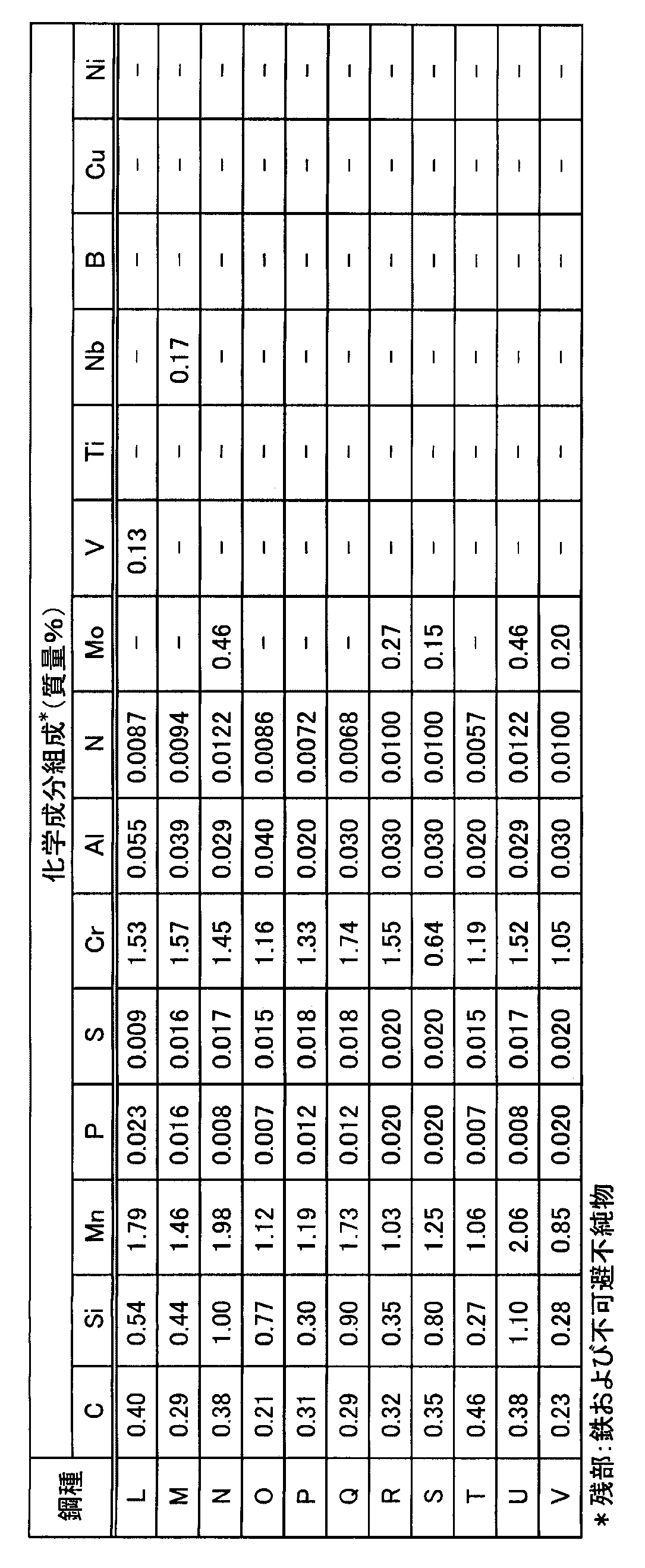
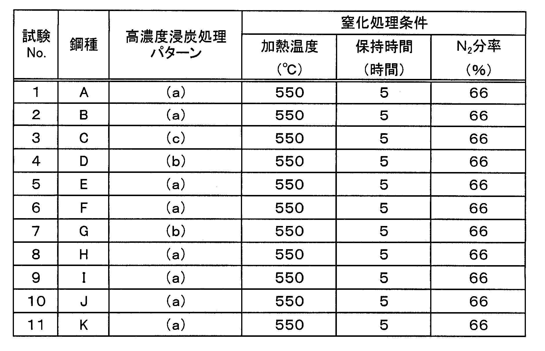
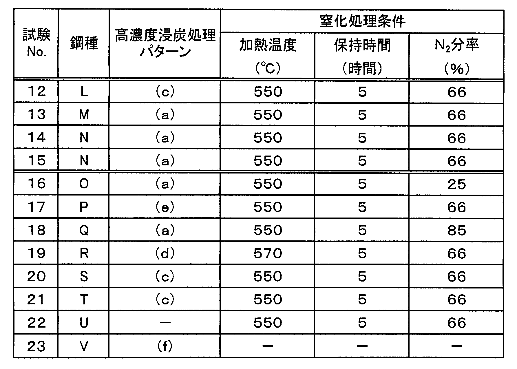
図1において、第1段階では高いカーボンポテンシャル(Cp)雰囲気で放置することにより高濃度浸炭し、更に第2段階で再加熱を行うことによって表層の浸炭部に微細な炭化物を析出させた。このとき、高濃度浸炭後の平均冷却速度は、50℃/秒とした。その後焼戻し処理を行い、プラズマ軟窒化処理(以下、単に「窒化処理」と呼ぶことがある)を行って表層部に窒素を高濃度に含有する組織を形成した。窒化処理後、仕上げ加工を行い、試験片とした。図2にローラーピッチング試験片の形状(仕上げ加工後)を示す。
このときの窒化処理条件[加熱温度、保持時間およびN2分率(N2分率以外は、C混合ガス(C3H8):1%、残部H2分率)]を、図1に示した各種パターン[添字(a)~(f)で表す]と共に、下記表3、4に示す(試験No.1~23)。
得られた各試験片について、表層部の各組織(炭化物の面積率、残留オーステナイトの面積率)および表面から20μm深さの窒素濃度を、下記の方法によって測定すると共に、部品特性(耐焼き付き性)を下記の方法によって評価した。
[表層部の炭化物面積率の測定方法]
組織中(主組織は焼戻しマルテンサイトおよび焼戻しベイナイトの少なくとも一方の組織)の炭化物の面積率は、窒化処理後の試験片を横断面で切断、樹脂に埋め込み、鏡面研磨、エッチングしたサンプルを用い、その表面から深さ20μmの位置を、走査型電子顕微鏡(SEM)を用いて測定した。高濃度浸炭を行うと、炭素が表層から内部に向けて拡散する。その結果、表層部から内部に向かって炭素の濃化層が形成され、それに伴って炭化物も形成される。ここでは、表面近傍における炭化物が重要であり、表面近傍における炭化物が面積率で5%以上あることが必要である。しかしながら、表面近傍の炭化物を直接測定することは困難であるため、ここでは表面近傍とほぼ同じ面積率になっている表面から20μm深さ位置における炭化物を表面近傍の炭化物と定義し、その面積率が5%以上であることを本発明の要件とした。任意の9μm×12μmの視野を、倍率8000倍で観察し、画像解析ソフトで炭化物の部分を識別し、その面積率を求めた。このとき測定は3視野行い、それら3視野の算術平均を炭化物の面積率とした。
組織中(主組織は焼戻しマルテンサイトおよび焼戻しベイナイトの少なくとも一方の組織)の炭化物の面積率は、窒化処理後の試験片を横断面で切断、樹脂に埋め込み、鏡面研磨、エッチングしたサンプルを用い、その表面から深さ20μmの位置を、走査型電子顕微鏡(SEM)を用いて測定した。高濃度浸炭を行うと、炭素が表層から内部に向けて拡散する。その結果、表層部から内部に向かって炭素の濃化層が形成され、それに伴って炭化物も形成される。ここでは、表面近傍における炭化物が重要であり、表面近傍における炭化物が面積率で5%以上あることが必要である。しかしながら、表面近傍の炭化物を直接測定することは困難であるため、ここでは表面近傍とほぼ同じ面積率になっている表面から20μm深さ位置における炭化物を表面近傍の炭化物と定義し、その面積率が5%以上であることを本発明の要件とした。任意の9μm×12μmの視野を、倍率8000倍で観察し、画像解析ソフトで炭化物の部分を識別し、その面積率を求めた。このとき測定は3視野行い、それら3視野の算術平均を炭化物の面積率とした。
[残留オーステナイトの面積率の測定方法]
試験片の一部を採出し、表面から深さ200μmの位置までの範囲を、50μmピッチ間隔(5箇所)で、微小部X線測定装置を用いて測定し、得られた残留オーステナイト量(残留γ面積率)の総和を5(測定箇所数)で除した値を採用した。
試験片の一部を採出し、表面から深さ200μmの位置までの範囲を、50μmピッチ間隔(5箇所)で、微小部X線測定装置を用いて測定し、得られた残留オーステナイト量(残留γ面積率)の総和を5(測定箇所数)で除した値を採用した。
[表面から20μm深さの窒素濃度の測定方法]
表層部(表面から20μm深さ位置)における窒素濃度は、前記試験片を横断面で切断、樹脂に埋め込み、鏡面研磨後、表層部から内部に向かって窒素濃度を、電子線マイクロプローブ分析計(Electron Probe Microanalyzer:EPMA)を用いた分析によって測定した。
表層部(表面から20μm深さ位置)における窒素濃度は、前記試験片を横断面で切断、樹脂に埋め込み、鏡面研磨後、表層部から内部に向かって窒素濃度を、電子線マイクロプローブ分析計(Electron Probe Microanalyzer:EPMA)を用いた分析によって測定した。
[部品特性の評価方法]
部品特性の評価方法として、ローラーピッチング試験を実施した。ローラーピッチング試験は、前記試験片(小ローラー)と、高炭素クロム軸受鋼SUJ2で作製された大ローラー(相手材)とを用いて、ローラーピッチング試験機によって行った。試験条件は、回転速度:1000rpm、相対すべり率:700%、油温:90℃で行い、焼付きの発生によって生じた振動で試験装置が停止するまでの回転数を求めた。このとき20000×103回を上限とし、焼付き発生寿命とした。10000×103回までに焼付きが発生しなかったものを、耐焼付き性に優れると評価した。
部品特性の評価方法として、ローラーピッチング試験を実施した。ローラーピッチング試験は、前記試験片(小ローラー)と、高炭素クロム軸受鋼SUJ2で作製された大ローラー(相手材)とを用いて、ローラーピッチング試験機によって行った。試験条件は、回転速度:1000rpm、相対すべり率:700%、油温:90℃で行い、焼付きの発生によって生じた振動で試験装置が停止するまでの回転数を求めた。このとき20000×103回を上限とし、焼付き発生寿命とした。10000×103回までに焼付きが発生しなかったものを、耐焼付き性に優れると評価した。
これらの結果(炭化物面積率、残留γ面積率、表層部窒素濃度、焼付き発生寿命)を、潤滑皮膜(潤滑皮膜はリン酸マンガンを使用)の有無と共に、下記表5、6に示す。尚、表6の焼付き発生寿命の項において「>20000」と表示したのは、20000×103回においても焼付きが発生しなかったことを意味する。
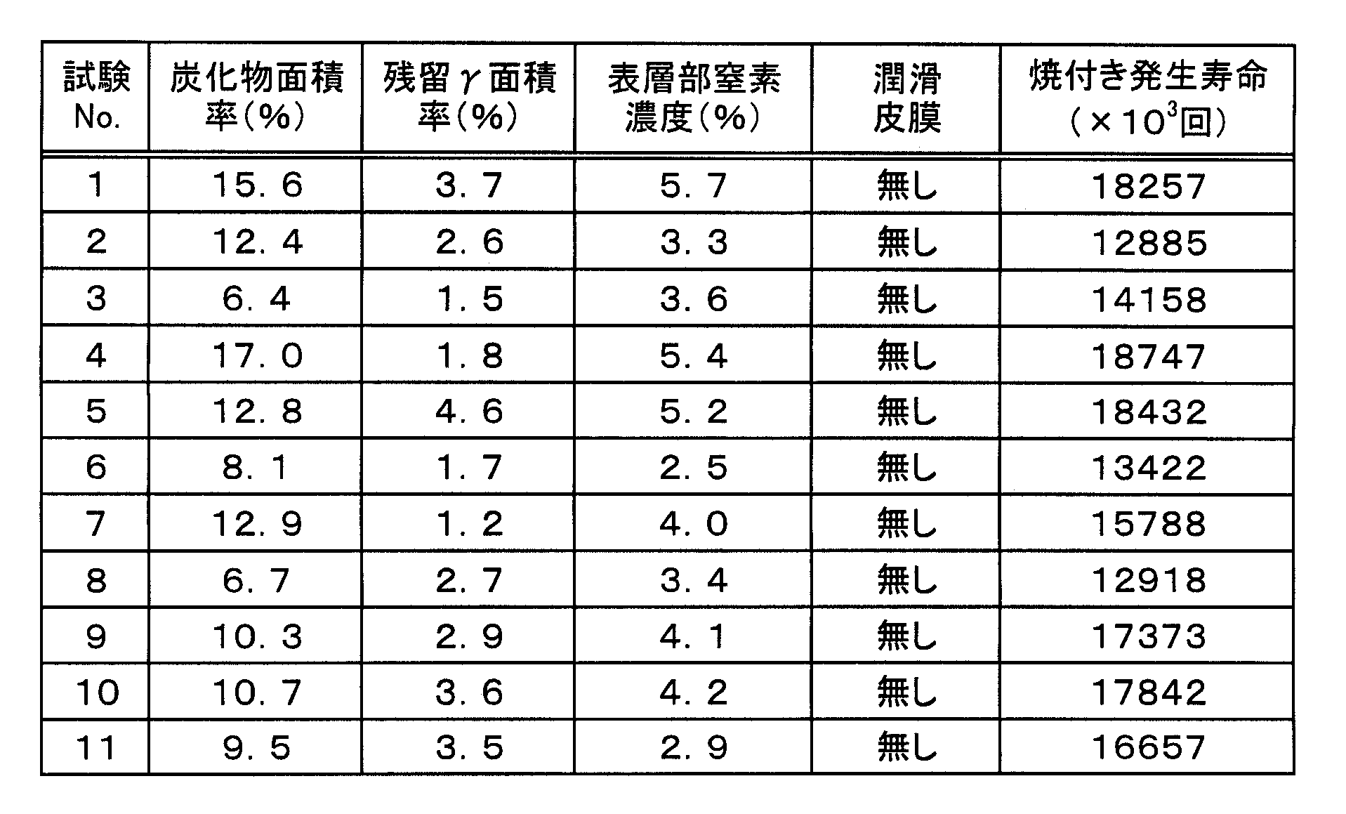

これらの結果から、次のように考察できる。まず試験No.1~15は、鋼材の化学成分組成および製造条件が共に適正な範囲で制御されているため、炭化物面積率、残留γ面積率および表層部窒素濃度のいずれも本発明で規定する範囲内に制御することができる。その結果、凝着抑制効果に優れ、優れた耐焼付き性を発揮することができる。また、潤滑皮膜を形成しても、優れた耐焼付き性を得ることができることが分かる。
これに対し、試験No.16~23は、鋼材の化学成分組成や製造条件が適正な範囲で制御されていないため、いずれも耐焼付き性が劣化している。即ち、試験No.16は、窒化処理の際の窒素ガス濃度(N2分率)が低過ぎるため、表層部窒素濃度が不足し、耐焼付き性が劣化している。試験No.17は、炭化物析出時の加熱温度が880℃と高すぎるため[熱処理パターン図1(e)]、炭化物面積率が確保できず、耐焼付き性が劣化している。
試験No.18は、窒化処理の際の窒素ガス濃度(N2分率)が高過ぎるため、表層部に窒素が濃化しすぎて耐焼付き性が劣化している。試験No.19は、浸炭時のカーボンポテンシャル(Cp)が低いため[熱処理パターン図1(d)]、炭化物面積率が確保できず、耐焼付き性が劣化している。
試験No.20は、Cr含有量が少ない鋼種(鋼種S)を用いたものであり、製造条件が適切であっても、炭化物面積率が確保できず、耐焼付き性が劣化している。試験No.21は、C含有量が過剰な鋼種(鋼種T)を用いたものであり、浸炭時の炭素浸入量不足となって炭化物面積率が確保できず、また表層の窒素濃度も低くなるため、耐焼付き性が劣化している。
試験No.22は、高濃度浸炭処理を省略したため、炭化物面積率が確保できず、また表層の窒素濃度も低くなるため、耐焼付き性が劣化している。試験No.23は、JIS SCM420相当鋼に、浸炭後、潤滑皮膜処理を行ったものであるが、高濃度浸炭、窒化処理を行っていないため[熱処理パターン図1(f)]、炭化物面積率が確保できず、また表層の窒素濃度も低くなり、更に残留γ量も多く存在するため、耐焼付き性が極端に劣化している。
(実施例2)
下記表7に示す各種化学成分組成の鋼材(鋼種B、W、X、Y:このうち鋼種Bは、前記表1に示した鋼種Bと同じ)を、小型炉によって溶製し、熱間鍛造後に溶体化処理および焼きならし処理を行い、引き継き、機械加工により直径:26mm×長さ:130mmのローラーピッチング試験片の形状に粗加工した。粗加工後の試験片に、前記図1(a)に示した熱処理パターンで、高濃度浸炭処理(浸炭、および炭化物析出処理)を行った。このとき、高濃度浸炭後の平均冷却速度は、50℃/秒とした。その後焼戻し処理を行い、窒化処理(プラズマ軟窒化処理またはプラズマ窒化処理)を行って、表層部に窒素を高濃度に含有する組織を形成した。窒化処理後、仕上げ加工を行い、試験片とした。実施例1と同様にローラーピッチング試験を行なった。
下記表7に示す各種化学成分組成の鋼材(鋼種B、W、X、Y:このうち鋼種Bは、前記表1に示した鋼種Bと同じ)を、小型炉によって溶製し、熱間鍛造後に溶体化処理および焼きならし処理を行い、引き継き、機械加工により直径:26mm×長さ:130mmのローラーピッチング試験片の形状に粗加工した。粗加工後の試験片に、前記図1(a)に示した熱処理パターンで、高濃度浸炭処理(浸炭、および炭化物析出処理)を行った。このとき、高濃度浸炭後の平均冷却速度は、50℃/秒とした。その後焼戻し処理を行い、窒化処理(プラズマ軟窒化処理またはプラズマ窒化処理)を行って、表層部に窒素を高濃度に含有する組織を形成した。窒化処理後、仕上げ加工を行い、試験片とした。実施例1と同様にローラーピッチング試験を行なった。
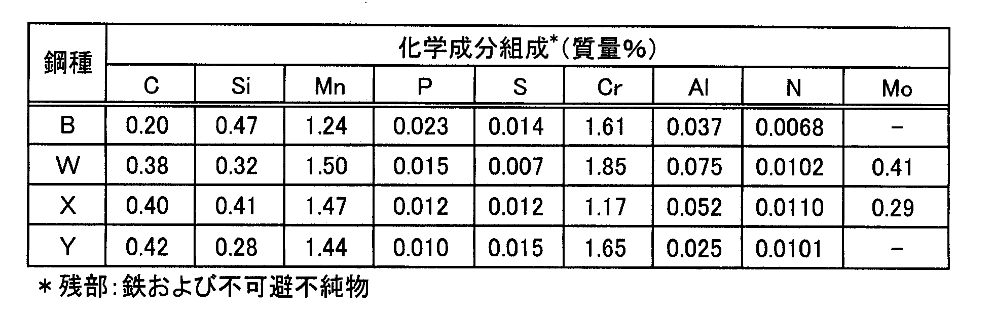
このときの窒化処理条件(加熱温度、保持時間、およびガス分率(N2、H2、C混合ガスの分率)を、下記表8に示す(試験No.24~30)。

得られた各試験片について、表層部の各組織(炭化物の面積率、残留γ面積率)、表面から20μm深さの窒素濃度(表層部窒素濃度)、および部品特性(耐焼き付き性)を、実施例1に示した方法によって測定すると共に、窒化層組成を下記の方法によって評価した。
(窒化層組成の測定方法)
試験片の一部を採出し、試験片表層部(表面から20μm深さまでの表層部)において、以下に示す測定条件でX線回折を行った。
試験片の一部を採出し、試験片表層部(表面から20μm深さまでの表層部)において、以下に示す測定条件でX線回折を行った。
(X線回折の測定条件)
分析装置:2次元微小部X線回折装置「RINT-RAPID II」株式会社リガク社製
(1)分析条件
管球:Co、単色化:モノクロメータを使用(Kα線)、管球出力:40kV-26mA、検出器:イメージングプレート(2次元)
(2)反射法
コリメータ:φ300μm、ω角(X線入射角):22°~30°揺動(1°/秒)、
φ角(面内回転):固定、測定時間(露光):30分
分析装置:2次元微小部X線回折装置「RINT-RAPID II」株式会社リガク社製
(1)分析条件
管球:Co、単色化:モノクロメータを使用(Kα線)、管球出力:40kV-26mA、検出器:イメージングプレート(2次元)
(2)反射法
コリメータ:φ300μm、ω角(X線入射角):22°~30°揺動(1°/秒)、
φ角(面内回転):固定、測定時間(露光):30分
得られたX線回折プロファイルから、試験片表層に存在する化合物を同定した。また、同定された化合物(成分)について、ピーク分離による半定量方法により、各成分の相対濃度を得た。表層の窒化鉄割合とは、X線回折の結果確認された、試験片表層に存在する全ての成分の相対濃度の合計(100質量%)に対する、Fe4NとFe2~3Nの合計相対濃度の割合(質量%)であり、窒化鉄中でのFe4Nとの割合とは、Fe4NとFe2~3Nの合計相対濃度に対するFe4Nの相対濃度の割合(質量%)のことであり、以下の式によって値を算出したものである。尚、試験片表層に存在する全ての成分とは、Fe4N、Fe2~3N、Fe5C2、Fe3C、γ-Fe、α-Fe等であり、基本的にはこれらの合計割合が100%となるのであるが、他の成分(例えば、Fe2C、Fe22C、Fe7C3等)が少量(5%以下)含まれていてもよい(含まれている場合には、これらの成分も合わせて100%となる)。
窒化鉄割合(質量%)={表層中のFe4Nの相対濃度(質量%)+表層中のFe2~3Nの相対濃度(質量%)}
窒化鉄中でのFe4Nの割合(質量%)={Fe4Nの相対濃度(質量%)/[Fe4Nの相対濃度(質量%)+Fe2~3Nの相対濃度(質量%)]}×100(%)
窒化鉄割合(質量%)={表層中のFe4Nの相対濃度(質量%)+表層中のFe2~3Nの相対濃度(質量%)}
窒化鉄中でのFe4Nの割合(質量%)={Fe4Nの相対濃度(質量%)/[Fe4Nの相対濃度(質量%)+Fe2~3Nの相対濃度(質量%)]}×100(%)
その結果を、一括して下記表9に示す。

この結果から明らかなように、いずれの場合においても、鋼材の化学成分組成および製造条件が共に適正な範囲で制御されているため、炭化物面積率、残留γ面積率および表層部窒素濃度のいずれも本発明で規定する範囲内に制御することができる。その結果、凝着抑制効果に優れ、優れた耐焼付き性を発揮することができる。このうち、特に試験No.25~27、29、30では、窒化層組成の好ましい要件をも満足するものであり、特に優れた耐焼付き性が得られていることが分かる。
本発明の歯車は、所定の化学成分組成を有し、表層部において、焼戻しマルテンサイトおよび焼戻しベイナイトの少なくとも一方の組織と、面積率1~10%で残留オーステナイトが存在すると共に、炭化物が面積率で5%以上析出している鋼材組織を有し、且つ表面から20μm深さにおける窒素濃度が2.0~6.0%であるものとすることによって、高回転・高すべり、低い動粘度の潤滑油が使用される動力伝達部において、より優れた耐焼付き性を発揮する。
Claims (8)
- C:0.15~0.45%(「質量%」の意味、化学成分組成について以下同じ)、Si:0.05~1.0%、Mn:1.0~2.0%、P:0.05%以下、S:0.05%以下、Cr:0.9~2%、Al:0.01~0.1%、およびN:0.02%以下を夫々含有し、残部が鉄および不可避不純物からなり、表層部において、焼戻しマルテンサイトおよび焼戻しベイナイトの少なくとも一方の組織と、面積率1~10%で残留オーステナイトが存在すると共に、炭化物が面積率で5%以上析出している鋼材組織を有し、且つ表面から20μm深さにおける窒素濃度が2.0~6.0%であることを特徴とする耐焼付き性に優れた歯車。
- 更に、Mo:0.5%以下(0%を含まない)を含有する請求項1に記載の歯車。
- 更に、V:0.2%以下(0%を含まない)、Ti:0.1%以下(0%を含まない)およびNb:0.2%以下(0%を含まない)よりなる群から選ばれる1種以上を含有する請求項1に記載の歯車。
- 更に、B:0.01%以下(0%を含まない)を含有する請求項1に記載の歯車。
- 更に、Cu:5%以下(0%を含まない)およびNi:5%以下(0%を含まない)よりなる群から選ばれる1種以上を含有する請求項1に記載の歯車。
- 表面から20μm深さまでの表層部において、窒化鉄の濃度が80質量%以上である窒化層が存在しており、当該窒化層は、窒化鉄中のFe4Nの割合が20質量%以上である請求項1に記載の歯車。
- 表面に潤滑皮膜が形成されたものである請求項1に記載の歯車。
- 電気自動車モータ用である請求項1に記載の歯車。
Priority Applications (3)
| Application Number | Priority Date | Filing Date | Title |
|---|---|---|---|
| US14/383,726 US9587288B2 (en) | 2012-03-30 | 2013-03-29 | Gear having excellent seizing resistance |
| CN201380017469.XA CN104220621B (zh) | 2012-03-30 | 2013-03-29 | 耐咬合性优异的齿轮 |
| EP13767691.2A EP2832877B1 (en) | 2012-03-30 | 2013-03-29 | Gear having excellent seizing resistance |
Applications Claiming Priority (2)
| Application Number | Priority Date | Filing Date | Title |
|---|---|---|---|
| JP2012082613 | 2012-03-30 | ||
| JP2012-082613 | 2012-03-30 |
Publications (1)
| Publication Number | Publication Date |
|---|---|
| WO2013147258A1 true WO2013147258A1 (ja) | 2013-10-03 |
Family
ID=49260497
Family Applications (1)
| Application Number | Title | Priority Date | Filing Date |
|---|---|---|---|
| PCT/JP2013/059737 Ceased WO2013147258A1 (ja) | 2012-03-30 | 2013-03-29 | 耐焼付き性に優れた歯車 |
Country Status (6)
| Country | Link |
|---|---|
| US (1) | US9587288B2 (ja) |
| EP (1) | EP2832877B1 (ja) |
| JP (1) | JP6088322B2 (ja) |
| CN (1) | CN104220621B (ja) |
| TW (1) | TWI507540B (ja) |
| WO (1) | WO2013147258A1 (ja) |
Cited By (1)
| Publication number | Priority date | Publication date | Assignee | Title |
|---|---|---|---|---|
| TWI789124B (zh) * | 2021-11-19 | 2023-01-01 | 財團法人金屬工業研究發展中心 | 碳鋼元件的製造方法 |
Families Citing this family (15)
| Publication number | Priority date | Publication date | Assignee | Title |
|---|---|---|---|---|
| JP6301145B2 (ja) * | 2014-02-05 | 2018-03-28 | 新日鐵住金株式会社 | スリーブ・ドッグギヤ |
| CN105039867A (zh) * | 2015-09-16 | 2015-11-11 | 广东韶钢松山股份有限公司 | 一种加氮20MnCr5齿轮钢及其生产方法 |
| CN106222605A (zh) * | 2016-08-29 | 2016-12-14 | 盐城圣奥热处理有限公司 | 一种齿轮渗碳淬火工艺 |
| JP6908485B2 (ja) | 2016-09-30 | 2021-07-28 | Dowaサーモテック株式会社 | 連続窒化処理炉および連続窒化処理方法 |
| CN108342640B (zh) * | 2017-01-22 | 2020-03-27 | 宝山钢铁股份有限公司 | 一种高淬透性齿轮钢及其制造方法 |
| CN106834960B (zh) * | 2017-01-24 | 2018-06-01 | 中天钢铁集团有限公司 | 一种汽车用含硼高级齿轮钢及其生产工艺 |
| CN108193121A (zh) * | 2017-12-29 | 2018-06-22 | 重庆全茂合渝科技有限公司 | 一种摩托车用齿轮及其制备工艺 |
| JP6881498B2 (ja) * | 2018-08-27 | 2021-06-02 | Jfeスチール株式会社 | 部品およびその製造方法 |
| JP7273324B2 (ja) | 2018-10-29 | 2023-05-15 | 日本製鉄株式会社 | 窒化部品粗形材、および窒化部品 |
| JP7365773B2 (ja) | 2019-02-13 | 2023-10-20 | 株式会社日立製作所 | 軟磁性材料及びその製造方法並びに軟磁性材料を用いた電動機 |
| JP7339560B2 (ja) * | 2019-04-02 | 2023-09-06 | 日本製鉄株式会社 | 窒化部品 |
| US11149832B2 (en) * | 2019-12-13 | 2021-10-19 | Aichi Steel Corporation | Differential hypoid gear, pinion gear, and paired hypoid gears formed by combination thereof |
| CN111500830B (zh) * | 2020-05-28 | 2021-02-26 | 中国矿业大学 | 一种渗碳零件回火热处理方法及渗碳零件 |
| JP7755131B2 (ja) * | 2021-09-03 | 2025-10-16 | 日本製鉄株式会社 | 窒化高周波焼入れ用鋼および窒化高周波焼入れ部品 |
| CN116555680B (zh) * | 2023-04-11 | 2025-03-07 | 江阴兴澄特种钢铁有限公司 | 一种新能源汽车高强度减速器齿轮用钢及其制造方法 |
Citations (9)
| Publication number | Priority date | Publication date | Assignee | Title |
|---|---|---|---|---|
| JPS62211094A (ja) | 1986-03-12 | 1987-09-17 | 株式会社廣瀬製作所 | ミシンのかまの製造方法 |
| JPH06172961A (ja) | 1992-12-09 | 1994-06-21 | Kobe Steel Ltd | 疲労強度特に面疲労強度に優れた機械構造用部品およびその製造方法 |
| JPH0953148A (ja) * | 1995-08-11 | 1997-02-25 | Kobe Steel Ltd | 高靭性肌焼き鋼製機械部品およびその製法 |
| JP2005068453A (ja) | 2003-08-28 | 2005-03-17 | Nissan Motor Co Ltd | 耐高面圧部品及びその製造方法 |
| JP2007284739A (ja) * | 2006-04-14 | 2007-11-01 | Sumitomo Metal Ind Ltd | 鋼製部品及びその製造方法 |
| JP2007308772A (ja) * | 2006-05-19 | 2007-11-29 | Kobe Steel Ltd | 浸炭部品およびその製造方法 |
| WO2009054530A1 (ja) * | 2007-10-24 | 2009-04-30 | Nippon Steel Corporation | 高温での面圧疲労強度に優れた浸炭窒化高周波焼入れ鋼部品及びその製造方法 |
| JP2010070827A (ja) * | 2008-09-22 | 2010-04-02 | Sumitomo Metal Ind Ltd | 鋼製の浸炭窒化部品 |
| JP2011225936A (ja) * | 2010-04-20 | 2011-11-10 | Daido Steel Co Ltd | 水素脆性型の面疲労強度に優れた浸炭窒化鋼 |
Family Cites Families (18)
| Publication number | Priority date | Publication date | Assignee | Title |
|---|---|---|---|---|
| DE69422146T2 (de) * | 1993-03-31 | 2000-08-24 | Hitachi Metals, Ltd. | GEGEN VERSCHLEISS UND FRESSEN WIDERSTANDSFäHIGE WALZE ZUM WARMWALZEN |
| EP0800538B1 (en) * | 1994-12-30 | 2001-05-09 | Eastman Chemical Company | Process for preparing cellulose esters using a sulfonic acid resin catalyst |
| JP3410947B2 (ja) | 1998-01-09 | 2003-05-26 | 日産自動車株式会社 | 無段変速機の転動体およびその製造方法 |
| JP2002286115A (ja) | 2001-03-23 | 2002-10-03 | Nissan Motor Co Ltd | 高強度歯車及びその製造方法 |
| JP4390576B2 (ja) * | 2003-03-04 | 2009-12-24 | 株式会社小松製作所 | 転動部材 |
| JP4390526B2 (ja) * | 2003-03-11 | 2009-12-24 | 株式会社小松製作所 | 転動部材およびその製造方法 |
| JP2005232543A (ja) | 2004-02-20 | 2005-09-02 | Nsk Ltd | ボールねじ |
| JP4352261B2 (ja) | 2005-02-21 | 2009-10-28 | 住友金属工業株式会社 | 歯車 |
| JP4970811B2 (ja) | 2006-03-13 | 2012-07-11 | 山陽特殊製鋼株式会社 | 高面圧用部品とその製造方法 |
| US20090192063A1 (en) * | 2008-01-25 | 2009-07-30 | Afton Chemical Corporation | Final Drive and Powershift Transmission Lubricants |
| JP5207805B2 (ja) | 2008-04-08 | 2013-06-12 | 株式会社神戸製鋼所 | 曲げ疲労強度に優れた鋼部品、及びその製造方法 |
| US20110041959A1 (en) | 2008-12-19 | 2011-02-24 | Atsushi Mizuno | Steel for machine structure use for surface hardening and steel part for machine structure use |
| JP5182067B2 (ja) | 2008-12-24 | 2013-04-10 | 新日鐵住金株式会社 | 真空浸炭または真空浸炭窒化用の鋼材 |
| ES2731643T3 (es) | 2009-01-16 | 2019-11-18 | Nippon Steel Corp | Acero para endurecimiento de superficies para uso estructural en máquinas y componente para uso estructural en máquinas |
| CN102089452A (zh) * | 2009-05-15 | 2011-06-08 | 新日本制铁株式会社 | 软氮化用钢和软氮化处理部件 |
| JP5632659B2 (ja) | 2010-06-17 | 2014-11-26 | 株式会社神戸製鋼所 | 熱処理歪みの少ない肌焼鋼 |
| KR20130036763A (ko) | 2010-08-12 | 2013-04-12 | 제이에프이 스틸 가부시키가이샤 | 가공성 및 내충격성이 우수한 고강도 냉연 강판 및 그 제조 방법 |
| TWI475114B (zh) | 2010-08-18 | 2015-03-01 | Jfe Steel Corp | High strength cold rolled steel sheet excellent in workability and impact resistance and a method of manufacturing the same |
-
2013
- 2013-03-29 JP JP2013075191A patent/JP6088322B2/ja active Active
- 2013-03-29 EP EP13767691.2A patent/EP2832877B1/en active Active
- 2013-03-29 CN CN201380017469.XA patent/CN104220621B/zh active Active
- 2013-03-29 TW TW102111634A patent/TWI507540B/zh active
- 2013-03-29 US US14/383,726 patent/US9587288B2/en active Active
- 2013-03-29 WO PCT/JP2013/059737 patent/WO2013147258A1/ja not_active Ceased
Patent Citations (9)
| Publication number | Priority date | Publication date | Assignee | Title |
|---|---|---|---|---|
| JPS62211094A (ja) | 1986-03-12 | 1987-09-17 | 株式会社廣瀬製作所 | ミシンのかまの製造方法 |
| JPH06172961A (ja) | 1992-12-09 | 1994-06-21 | Kobe Steel Ltd | 疲労強度特に面疲労強度に優れた機械構造用部品およびその製造方法 |
| JPH0953148A (ja) * | 1995-08-11 | 1997-02-25 | Kobe Steel Ltd | 高靭性肌焼き鋼製機械部品およびその製法 |
| JP2005068453A (ja) | 2003-08-28 | 2005-03-17 | Nissan Motor Co Ltd | 耐高面圧部品及びその製造方法 |
| JP2007284739A (ja) * | 2006-04-14 | 2007-11-01 | Sumitomo Metal Ind Ltd | 鋼製部品及びその製造方法 |
| JP2007308772A (ja) * | 2006-05-19 | 2007-11-29 | Kobe Steel Ltd | 浸炭部品およびその製造方法 |
| WO2009054530A1 (ja) * | 2007-10-24 | 2009-04-30 | Nippon Steel Corporation | 高温での面圧疲労強度に優れた浸炭窒化高周波焼入れ鋼部品及びその製造方法 |
| JP2010070827A (ja) * | 2008-09-22 | 2010-04-02 | Sumitomo Metal Ind Ltd | 鋼製の浸炭窒化部品 |
| JP2011225936A (ja) * | 2010-04-20 | 2011-11-10 | Daido Steel Co Ltd | 水素脆性型の面疲労強度に優れた浸炭窒化鋼 |
Cited By (1)
| Publication number | Priority date | Publication date | Assignee | Title |
|---|---|---|---|---|
| TWI789124B (zh) * | 2021-11-19 | 2023-01-01 | 財團法人金屬工業研究發展中心 | 碳鋼元件的製造方法 |
Also Published As
| Publication number | Publication date |
|---|---|
| US20150038380A1 (en) | 2015-02-05 |
| EP2832877A1 (en) | 2015-02-04 |
| TWI507540B (zh) | 2015-11-11 |
| EP2832877A4 (en) | 2016-04-06 |
| CN104220621B (zh) | 2017-04-12 |
| CN104220621A (zh) | 2014-12-17 |
| JP2013227674A (ja) | 2013-11-07 |
| JP6088322B2 (ja) | 2017-03-01 |
| TW201408790A (zh) | 2014-03-01 |
| US9587288B2 (en) | 2017-03-07 |
| EP2832877B1 (en) | 2017-10-11 |
Similar Documents
| Publication | Publication Date | Title |
|---|---|---|
| JP6088322B2 (ja) | 耐焼付き性に優れた歯車 | |
| JP4659139B2 (ja) | 高周波焼入れ用鋼 | |
| JP4956146B2 (ja) | 鍛造性と結晶粒粗大化防止特性に優れた肌焼鋼およびその製造方法並びに浸炭部品 | |
| JP5299118B2 (ja) | 真空浸炭用鋼および真空浸炭部品 | |
| JPWO2012077705A1 (ja) | 面疲労強度に優れたガス浸炭鋼部品、ガス浸炭用鋼材およびガス浸炭鋼部品の製造方法 | |
| JP5886119B2 (ja) | 肌焼鋼鋼材 | |
| JP4688727B2 (ja) | 浸炭部品およびその製造方法 | |
| WO2016152167A1 (ja) | 軟窒化用鋼および部品並びにこれらの製造方法 | |
| JP6111121B2 (ja) | 耐焼付き性に優れた歯車 | |
| JP2006307273A (ja) | 耐結晶粒粗大化特性と冷間加工性に優れた軟化焼鈍の省略可能な肌焼用鋼およびその製法 | |
| JP4451808B2 (ja) | 疲労特性と耐結晶粒粗大化特性に優れた肌焼用圧延棒鋼およびその製法 | |
| JP4502929B2 (ja) | 転動疲労特性および結晶粒粗大化防止特性に優れた肌焼用鋼 | |
| JP4737601B2 (ja) | 高温窒化処理用鋼 | |
| JP6043078B2 (ja) | 耐焼付き性に優れた電気自動車モータ用歯車 | |
| JPH11229032A (ja) | 軟窒化用鋼材の製造方法及びその鋼材を用いた軟窒化部品 | |
| JP5077814B2 (ja) | シャフト及びその製造方法 | |
| JP2006307270A (ja) | 耐結晶粒粗大化特性と冷間加工性に優れた肌焼用鋼およびその製法 | |
| JP7755132B2 (ja) | 窒化高周波焼入れ用鋼および窒化高周波焼入れ部品 | |
| JP2006161143A (ja) | 転動疲労寿命と高温浸炭特性に優れた浸炭用鋼材 | |
| JP2003160810A (ja) | 疲労強度に優れた浸炭鋼部品の製法 | |
| WO2017122612A1 (ja) | 浸炭窒化用鋼材および浸炭窒化部品 | |
| JP2024034953A (ja) | 鋼材及び鋼部品 | |
| JP2018003076A (ja) | 軟窒化用鋼および部品ならびにこれらの製造方法 | |
| JP2025156057A (ja) | 浸炭窒化鋼材 | |
| JP2022157220A (ja) | はだ焼鋼および浸炭部品 |
Legal Events
| Date | Code | Title | Description |
|---|---|---|---|
| 121 | Ep: the epo has been informed by wipo that ep was designated in this application |
Ref document number: 13767691 Country of ref document: EP Kind code of ref document: A1 |
|
| REEP | Request for entry into the european phase |
Ref document number: 2013767691 Country of ref document: EP |
|
| WWE | Wipo information: entry into national phase |
Ref document number: 14383726 Country of ref document: US Ref document number: 2013767691 Country of ref document: EP |
|
| NENP | Non-entry into the national phase |
Ref country code: DE |