WO2013151402A1 - Appareil de boîte de vitesses - Google Patents
Appareil de boîte de vitesses Download PDFInfo
- Publication number
- WO2013151402A1 WO2013151402A1 PCT/KR2013/002914 KR2013002914W WO2013151402A1 WO 2013151402 A1 WO2013151402 A1 WO 2013151402A1 KR 2013002914 W KR2013002914 W KR 2013002914W WO 2013151402 A1 WO2013151402 A1 WO 2013151402A1
- Authority
- WO
- WIPO (PCT)
- Prior art keywords
- gear
- brake member
- planetary
- cage
- rotation
- Prior art date
- Legal status (The legal status is an assumption and is not a legal conclusion. Google has not performed a legal analysis and makes no representation as to the accuracy of the status listed.)
- Ceased
Links
Images




Classifications
-
- F—MECHANICAL ENGINEERING; LIGHTING; HEATING; WEAPONS; BLASTING
- F16—ENGINEERING ELEMENTS AND UNITS; GENERAL MEASURES FOR PRODUCING AND MAINTAINING EFFECTIVE FUNCTIONING OF MACHINES OR INSTALLATIONS; THERMAL INSULATION IN GENERAL
- F16H—GEARING
- F16H57/00—General details of gearing
- F16H57/08—General details of gearing of gearings with members having orbital motion
- F16H57/10—Braking arrangements
-
- F—MECHANICAL ENGINEERING; LIGHTING; HEATING; WEAPONS; BLASTING
- F16—ENGINEERING ELEMENTS AND UNITS; GENERAL MEASURES FOR PRODUCING AND MAINTAINING EFFECTIVE FUNCTIONING OF MACHINES OR INSTALLATIONS; THERMAL INSULATION IN GENERAL
- F16H—GEARING
- F16H3/00—Toothed gearings for conveying rotary motion with variable gear ratio or for reversing rotary motion
- F16H3/44—Toothed gearings for conveying rotary motion with variable gear ratio or for reversing rotary motion using gears having orbital motion
-
- F—MECHANICAL ENGINEERING; LIGHTING; HEATING; WEAPONS; BLASTING
- F16—ENGINEERING ELEMENTS AND UNITS; GENERAL MEASURES FOR PRODUCING AND MAINTAINING EFFECTIVE FUNCTIONING OF MACHINES OR INSTALLATIONS; THERMAL INSULATION IN GENERAL
- F16H—GEARING
- F16H3/00—Toothed gearings for conveying rotary motion with variable gear ratio or for reversing rotary motion
- F16H3/44—Toothed gearings for conveying rotary motion with variable gear ratio or for reversing rotary motion using gears having orbital motion
- F16H3/62—Gearings having three or more central gears
- F16H3/66—Gearings having three or more central gears composed of a number of gear trains without drive passing from one train to another
- F16H3/663—Gearings having three or more central gears composed of a number of gear trains without drive passing from one train to another with conveying rotary motion between axially spaced orbital gears, e.g. a stepped orbital gear or Ravigneaux
-
- B—PERFORMING OPERATIONS; TRANSPORTING
- B60—VEHICLES IN GENERAL
- B60L—PROPULSION OF ELECTRICALLY-PROPELLED VEHICLES; SUPPLYING ELECTRIC POWER FOR AUXILIARY EQUIPMENT OF ELECTRICALLY-PROPELLED VEHICLES; ELECTRODYNAMIC BRAKE SYSTEMS FOR VEHICLES IN GENERAL; MAGNETIC SUSPENSION OR LEVITATION FOR VEHICLES; MONITORING OPERATING VARIABLES OF ELECTRICALLY-PROPELLED VEHICLES; ELECTRIC SAFETY DEVICES FOR ELECTRICALLY-PROPELLED VEHICLES
- B60L2240/00—Control parameters of input or output; Target parameters
- B60L2240/40—Drive Train control parameters
- B60L2240/48—Drive Train control parameters related to transmissions
- B60L2240/486—Operating parameters
-
- F—MECHANICAL ENGINEERING; LIGHTING; HEATING; WEAPONS; BLASTING
- F16—ENGINEERING ELEMENTS AND UNITS; GENERAL MEASURES FOR PRODUCING AND MAINTAINING EFFECTIVE FUNCTIONING OF MACHINES OR INSTALLATIONS; THERMAL INSULATION IN GENERAL
- F16H—GEARING
- F16H2200/00—Transmissions for multiple ratios
- F16H2200/0021—Transmissions for multiple ratios specially adapted for electric vehicles
-
- F—MECHANICAL ENGINEERING; LIGHTING; HEATING; WEAPONS; BLASTING
- F16—ENGINEERING ELEMENTS AND UNITS; GENERAL MEASURES FOR PRODUCING AND MAINTAINING EFFECTIVE FUNCTIONING OF MACHINES OR INSTALLATIONS; THERMAL INSULATION IN GENERAL
- F16H—GEARING
- F16H2200/00—Transmissions for multiple ratios
- F16H2200/003—Transmissions for multiple ratios characterised by the number of forward speeds
- F16H2200/0034—Transmissions for multiple ratios characterised by the number of forward speeds the gear ratios comprising two forward speeds
-
- F—MECHANICAL ENGINEERING; LIGHTING; HEATING; WEAPONS; BLASTING
- F16—ENGINEERING ELEMENTS AND UNITS; GENERAL MEASURES FOR PRODUCING AND MAINTAINING EFFECTIVE FUNCTIONING OF MACHINES OR INSTALLATIONS; THERMAL INSULATION IN GENERAL
- F16H—GEARING
- F16H2200/00—Transmissions for multiple ratios
- F16H2200/20—Transmissions using gears with orbital motion
- F16H2200/2002—Transmissions using gears with orbital motion characterised by the number of sets of orbital gears
- F16H2200/2005—Transmissions using gears with orbital motion characterised by the number of sets of orbital gears with one sets of orbital gears
-
- F—MECHANICAL ENGINEERING; LIGHTING; HEATING; WEAPONS; BLASTING
- F16—ENGINEERING ELEMENTS AND UNITS; GENERAL MEASURES FOR PRODUCING AND MAINTAINING EFFECTIVE FUNCTIONING OF MACHINES OR INSTALLATIONS; THERMAL INSULATION IN GENERAL
- F16H—GEARING
- F16H2200/00—Transmissions for multiple ratios
- F16H2200/20—Transmissions using gears with orbital motion
- F16H2200/203—Transmissions using gears with orbital motion characterised by the engaging friction means not of the freewheel type, e.g. friction clutches or brakes
- F16H2200/2038—Transmissions using gears with orbital motion characterised by the engaging friction means not of the freewheel type, e.g. friction clutches or brakes with three engaging means
Definitions
- the present invention relates to a transmission device, and more particularly, to a transmission device capable of multi-stage rotation with a simple structure including a composite planetary gear set and capable of stopping and opening operations.
- the electric motor has a speed-torque characteristic suitable for driving a car than an engine, but also has low energy efficiency in the low speed and high speed areas, and thus, when the electric motor is operated in these areas, the efficiency decreases and heat generation becomes severe. Therefore, if the mechanical transmission can be used with the motor can increase the performance of the electric vehicle.
- the currently developed transmissions have a complicated structure, a large size, and an axially long structure, so that it is difficult to mount them together with a motor in an automobile wheel, and in the case of an automobile wheel, high torque low speed rotation and low torque high speed rotation
- the brake operation since the brake operation, the opening operation to allow a person to push the car, there is a problem that it is difficult to install in the wheel using the existing transmission.
- an object of the present invention is to provide a transmission apparatus capable of performing multi-stage rotation, stop operation, and opening operation through the composite planetary gear set.
- a speed change device for performing a shift between the input end and the output end, the sun gear connected to the input end;
- a second planetary gear which forms a concentric circle with each of the first planetary gears and is integrally formed with the first planetary gear;
- a brake member wherein the brake member can act on the second ring gear and the cage to control the rotation of the second ring gear and the rotation of the cage.
- the brake member comprises a first brake member acting on the second ring gear, and a second brake member acting on the cage.
- the brake member is composed of a friction brake.
- a sixth gear is formed around the outer circumferential surface of the second ring gear
- a seventh gear is formed around the outer circumferential surface of the cage
- the brake member is the sixth gear.
- a first brake member having an eighth tooth that engages with the gear
- a second brake member having a ninth tooth that engages with the seventh gear.
- the first and second brake members respectively, the rack gear having an eighth and ninth gears, a spring for applying elasticity to the rack gear, the displacement of the rack gear And a guide rail for guiding, a rotation axis acting as a rotation center of the guide rail, and a power transmission unit for displacing the rack gear.
- a speed shift device wherein the speed change device performs shifting between an input end and an output end, the first sun gear; A second sun gear having a rotation axis overlapping with the rotation axis of the first sun gear; Several first planetary gears circumscribed and engaged with the first sun gear; A second planetary gear that forms a concentric circle with each of the first planetary gears and is integrally formed with the first planetary gear and is externally engaged with the second sun gear; A first ring gear externally engaged with the first planetary gear; A second ring gear that is externally engaged with the second planetary gear; A cage supporting the rotation axis of the first planetary gear and the second planetary gear so that the first planetary gear and the second planetary gear can revolve around the first and second sun gears; And a brake member;
- the rotation axis of the first sun gear, the rotation axis of the second sun gear, the rotation axis of the first ring gear, the rotation axis of the second ring gear, and the rotation axis of the cage are the input ends, and the other is the output end.
- the brake member may perform gear shifting, gear stop, and gear opening as the brake member acts on at least one of three rotation shafts except for the input stage and the output stage.
- the brake member includes a first brake member, a second brake member, and a third brake member,
- the first brake member, the second brake member, and the third brake member may each include a rotation shaft of the first sun gear, a rotation shaft of the second sun gear, a rotation shaft of the first ring gear, a rotation shaft of the second ring gear, And a rotation axis of the cage.
- gear shifting is performed as any one of the first to third brake members operates on any one of the rotary shafts, and two or more of the first to third brake members are A gear stop is performed in accordance with any one of the rotary shafts, and gear opening is performed as the first to third brake members do not operate with respect to the rotary shaft.
- At least one of the first to third brake members is composed of a friction brake.
- a first gear is formed on each of the remaining rotation shafts except for the input end and the output end, and at least one of the first to third brake members is engaged with the first gear. It is composed of a gear brake including a second gear that can stop the rotation of the rotary shaft.
- the gear brake a gear gear having a gear portion, a spring for applying elasticity to the rack gear, a guide rail for guiding displacement of the rack gear, the center of rotation of the guide rail It includes a rotation axis that acts as, and a power transmission for displacing the rack gear.
- the first sun gear and the input end are connected, and any one of the second sun gear, the first ring gear, and the second ring gear is connected to the output end;
- the second sun gear and the input end are connected, and the second sun gear or the cage is connected to the output end;
- the first ring gear is connected to an input end and the first sun gear or the cage is connected to an output end;
- the second ring gear is connected to an input terminal and the first sun gear is connected to an output terminal;
- the rotation direction of the output end is not changed even when the brake member acts on any of the remaining three rotation shafts.
- the first sun gear and the input terminal are connected and the second ring gear and the output terminal are connected;
- the first ring gear and the input terminal are connected and the cage and the output terminal are connected;
- the second ring gear and the input terminal are connected, and the first sun gear and the output terminal are connected;
- the cage and the input terminal are connected, and the first ring gear and the output terminal are connected.
- the speed change device a speed change device for performing a shift between the input end and the output end
- the transmission device includes N gear stages (N> 2) having a multi-stage structure; Cage; And a brake member; Including;
- Each gear stage may include at least one of a sun gear and a ring gear; And several planetary gears; Including;
- the sun gear is disposed at the orbital center of the several planetary gears, the several planetary gears are externally meshed with the solar gear, the ring gears are internally meshed with the several planetary gears, and the plurality of planetary gears are meshed.
- Each sun gear included in the gear stage is arranged on the coaxial line, each having a separate axis, each planetary gear included in the plurality of gear stages are arranged to correspond to each other by gear stages and a plurality of gears corresponding to each gear stage Planetary gears are formed concentrically and integrally,
- the cage supports a rotating shaft of the planetary gear so that the planetary gear revolves around the sun gear
- the brake member includes a rotating shaft of the sun gear, a rotating shaft of the ring gear, and a rotating shaft of the cage.
- the diameters of the several sun gears are configured differently from each other.
- the several sun gears are arranged such that diameters increase or decrease in sequence in the arrangement direction of the plurality of gear stages.
- the brake member is composed of a friction brake.
- the brake member is composed of a gear brake having a first gear, and at least a portion of the shaft of the cage, the ring gear, and the sun gear, the first gear provided in the gear brake.
- a second gear is formed to engage the portion.
- the brake member may include a rack gear having a gear, a spring that elastically applies the rack gear, a guide rail for guiding displacement of the rack gear, a rotation shaft acting as a rotation center of the guide rail, And a power transmission for displacing the rack gear.
- the brake member is composed of a variable brake member capable of acting on each gear stage by displacing in the direction in which the plurality of gear stages are arranged.
- the gear stop is performed as the brake member is applied to two or more of the rotary shafts other than the input stage and the output stage,
- Gear opening is performed as the brake member does not operate with respect to the rotational axis.
- the speed of the output shaft changes.
- the complex planetary gear set includes a complex and simple structure, and has a structure that does not have an axially extending structure and is reduced in size, thereby improving space utilization.
- the multi-speed planetary gear set may perform a multi-speed rotation, a stop operation, and an opening operation.
- FIG. 1 is a view showing a transmission device according to an embodiment of the present invention.
- FIG. 2 is a view showing a transmission apparatus according to an embodiment of the present invention.
- FIG. 3 is a view showing a transmission apparatus according to an embodiment of the present invention.
- FIG. 4 is a view showing a transmission apparatus according to an embodiment of the present invention.
- FIG. 5 is a view showing a transmission device according to an embodiment of the present invention.
- FIG. 6 is a view showing a transmission device according to an embodiment of the present invention.
- FIG. 7 is an exploded view of the transmission device according to FIGS. 4 to 6.
- FIG. 8 is a view showing the operation of the transmission apparatus according to an embodiment of the present invention.
- FIG. 9 is a view showing the operation of the transmission apparatus according to an embodiment of the present invention.
- FIG. 10 is a view showing a transmission apparatus according to an embodiment of the present invention.
- FIG. 11 is a view showing a transmission device according to an embodiment of the present invention.
- FIG. 12 is a view showing the operation of the transmission apparatus according to an embodiment of the present invention.
- FIG. 13 is a view showing the structure of the gear stage of the transmission according to an embodiment of the present invention.
- FIG. 14 is a view showing a transmission device according to an embodiment of the present invention.
- 15 is a view showing a transmission device according to an embodiment of the present invention.
- 16 is a view showing the structure of a transmission gear stage according to an embodiment of the present invention.
- 17 is a view showing a transmission device according to an embodiment of the present invention.
- FIG. 18 is a view showing a transmission device according to an embodiment of the present invention.
- 19 is a view showing a transmission device according to an embodiment of the present invention.
- a transmission device comprising: a sun gear connected to an input end as a shift device configured to perform a shift between an input end and an output end; A plurality of first planetary gears externally engaged with the sun gear; A second planetary gear which forms a concentric circle with each of the first planetary gears and is integrally formed with the first planetary gear; A first ring gear meshed with the first planetary gear and engaged with the output shaft; A second ring gear that is externally engaged with the second planetary gear; A cage supporting the rotating shafts of the first planetary gear and the second planetary gear so that the first planetary gear and the second planetary gear revolve around the sun gear; And a brake member, wherein the brake member can act on the second ring gear and the cage to control the rotation of the second ring gear and the rotation of the cage.
- spatially relative terms “bottom”, “top”, “side”, etc., as shown in the figures, may be used to easily describe the correlation of one member or component with another member or component.
- Spatially relative terms should be understood to include terms in which the members are shown in different directions in use or operation in addition to the directions shown in the figures, for example, when the members shown in the figures are reversed.
- a member described as “top” of may be placed at the “bottom” of another member, thus, the exemplary term “top” may include both the up and down directions.
- spatially relative terms may be interpreted according to orientation.
- FIG. 1 to 3 is a view showing a speed change device according to an embodiment of the present invention
- Figures 4 to 6 is a view showing a speed change device according to another embodiment
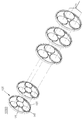
- Figure 7 is a shift according to Figures 4 to 6 An exploded view of the device.
- the speed change apparatus 1 includes a sun gear 110 connected to an input terminal, and several first planetary gears 120 engaged with the sun gear 110. And a second planetary gear 130 which is formed concentrically with each of the first planetary gears 120 and integrally formed with the first planetary gear 120, and is engaged with the first planetary gear 120 and outputs.
- the first ring gear 140 connected to the second ring gear 150, the second ring gear 150 engaged with the second planetary gear 130, the first planetary gear 120, and the second planetary gear 130. It supports a rotating shaft, and comprises a cage 160, which is concentric with the output side of the first and second planetary gear 130, and a brake member.
- the sun gear 110 is connected to the input terminal 10, for example, the rotational axis of the input shaft and the rotating shaft of the sun gear 110 may be connected to receive power from the input terminal (10).
- the input terminal 10 may be, for example, a predetermined driving motor, but is not limited thereto.
- the sun gear 110 may rotate by power received from the input terminal 10.
- the main frame 20 may be provided for mounting and support of the transmission device (1).
- the first planetary gear 120 is configured to be engaged with the sun gear 110 and to rotate in accordance with the rotation of the sun gear 110. 1 to 7, the number of the first planetary gears 120 is illustrated as three, but the present invention is not limited thereto and several first planetary gears 120 engaged with the sun gear 110 may be disposed.
- the sun gear 110 is disposed between the plurality of first planetary gears 120, so that the sun gear 110 is inscribed with the plurality of first planetary gears 120, and the first planetary gear 120 is a sun gear. Circumscribe and engage about 110. Therefore, the rotational force may be applied to the entire first planetary gear 120 by being disposed in a space between the plurality of first planetary gears 120.
- the second planetary gear 130 shares a rotation axis with each of the first planetary gears 120 and forms concentric circles. That is, the second planetary gear 130 is disposed in the same number as the first planetary gear 120, and each of the first planetary gear 120 and the second planetary gear 130 shares a rotation axis and forms concentric circles.
- the first planetary gear 120 and the second planetary gear 130 rotate together, and the angular velocity is configured to be the same.
- first and second planetary gears 120 and 130 are illustrated to be integrally in contact with each other, but the present invention is not limited thereto.
- the first and second planetary gears 120 and 130 may be formed of the first and second planetary gears 120 and 130. 2 may be spaced apart from each other by a connecting means such as a predetermined shaft (not shown) connecting the central axis of the planetary gears (120, 130), but is not limited thereto.
- the first ring gear 140 meshes with the first planetary gear 120 and is configured to rotate according to the rotation of the first planetary gear 120. That is, the plurality of first planetary gears 120 are externally engaged with the sun gear 110, and the first ring gear 140 is externally engaged with the plurality of first planetary gears 120. In this case, the rotation center axis of the first ring gear 140 may overlap with the rotation center axis of the sun gear 110.
- the first ring gear 140 is connected to an output end (not shown), and the output end (not shown) is connected to, for example, a rotating shaft of the first ring gear 140 extending from the first ring gear 140, Or it may be connected via a belt connected to the outer circumference of the first ring gear 140, but is not limited thereto.
- the second ring gear 150 circumscribes and engages with the second planetary gear 130.
- the second ring gear 150 may rotate according to the rotation of the second planetary gear 130, and the rotation axis of the second ring gear 150 may also rotate the sun gear 110 and the first ring gear 140. It can be configured to overlap with the axis.
- the radius of the first planetary gear 120 is larger than that of the second planetary gear 130. Therefore, the diameter of the first ring gear 140 circumscribed with the first planetary gear 120 may be larger than the diameter of the second ring gear 140 circumscribed with the second planetary gear 130.
- the cage 160 is provided at the lower end of the second planetary gear 130 and supports the rotating shafts of the first and second planetary gears 120 and 130.
- the first and second planetary gears 120 and 130 may include a predetermined shaft that forms a rotating shaft, and the cage 160 may have a hole into which the shaft is inserted to rotate.
- the upper cage 170 for supporting the rotating shaft of the first and second planetary gear on the first planetary gear may be provided.
- the cage 160 has a rotating shaft, and the rotating shafts of the sun gear 110, the first ring gear 140, and the second ring gear 150 and the rotating shafts of the cage 160 may overlap each other.
- the cage 160 has a rotating shaft overlapping with the rotating shaft of the sun gear 110 and is configured to support the rotating shafts of the first and second planetary gears 120 and 130, thereby providing the first and second planetary gears 120 and 130.
- C) rotates around the sun gear 110 as the shaft acting as the rotation axis of the first and second planetary gears 120 and 130 rotates around the sun gear 110. It can rotate in the same direction as the revolution direction.
- a brake member capable of stopping the rotation of the second ring gear 150 and the cage 160, respectively. That is, the brake member stops the rotation of the second ring gear and the cage 160 all, or stops the rotation of any one of the second ring gear 150 and the cage 160, or the second ring gear ( The second ring gear 150 and the cage 160 may both rotate by not stopping the rotation of both the 150 and the cage 160. Accordingly, the brake member may include a first brake member acting on the second ring gear 150 and a second brake member acting on the cage.
- the brake member may be, for example, a predetermined friction brake 200 as shown in FIGS.
- the friction brake 200 may stop the rotation of the second ring gear 150 and the cage 160 by applying friction to the second ring gear 150 and the cage 160, respectively.
- the brake member may be, for example, toothed brakes 300a and 300b having predetermined teeth T8 and T9, as shown in FIGS. 4 to 7.
- the first gear T1 of the sun gear 110 and the first gear T2 of the first planetary gear 120 mesh with each other, and the first planetary gear 120 is formed of a first gear. It can be seen that the second gear T2 of the first planetary gear 120 meshes with the fourth gear T4 of the first ring gear 140 by being external to the first ring gear 140.
- the third gear T3 formed on the second planetary gear 130 meshes with the fifth gear T5 formed on the inner circumferential surface of the second ring gear 150, and the second ring gear 150 and the cage It can be seen that the sixth and seventh gear parts T6 and T7 are formed on the outer circumferential surface of the 160, respectively.
- sixth and seventh gear parts T6 and T7 are formed around the cage 160 and the second ring gear 150, respectively, and are engaged with the sixth and seventh gear parts T6 and T7.
- Gear brakes 300a and 300b having eighth and ninth gears T8 and T9 are provided, and the second ring gear 150 is engaged with the gears T6, T7, T8 and T9. And rotation of the cage 160 may be stopped.
- the gear brakes 300a and 300b are elastic to the rack gear 310 and the rack gear 310 having the eighth and ninth gears T8 and T9. Displace the spring 320, the guide rail 330 for guiding the displacement of the rack gear 310, the rotation axis 340 acting as a rotation center of the guide rail 330, and the rack gear 310 It may be configured to include a power transmission unit 350.
- the gear brakes 300a and 300b may include a first gear brake 300a acting on the second ring gear 150 and a second gear brake 300b acting on the cage 160.
- the first gear brake 300a and the second gear brake 300b may have the same structure.
- the power transmission unit 350 displaces the rack gear 310 and thus the gear T8 of the rack gear 310. Is engaged with the sixth gear T6 formed around the second ring gear 150. At this time, the engagement between the rack gear 310 and the gear brake 300a may be performed as the rack gear 310 is guided along the guide rail 330.
- the gear brakes 300a and 300b include a spring 320 member that applies elasticity to the rack gear 310 and thus includes a gear formed on the rack gear 310 and a fifth ring gear 150 formed on the second ring gear 150.
- first stage gear state illustrates a state in which the brake member acts on the second ring gear 150 and the brake member does not act on the cage 160. This state is hereinafter referred to as "first stage gear state”.
- the rotation of the second ring gear 150 stops as the brake member acts on the second ring gear 150, and the brake member does not act on the cage 160.
- rotation of the first and second planetary gear 130 is not interrupted, so that the first and second planetary gears 130 rotate and rotate at the same time.
- the first ring gear 140 engaged with the first planetary gear 120 also rotates by the rotation of the first planetary gear 120.
- the rotation direction of the first ring gear 140 is opposite to the rotation direction of the first planetary gear 120 and has the same direction as the rotation direction of the sun gear 110.
- the rotation direction Q of the first planetary gear 120 is opposite to the rotation direction P of the sun gear 110.
- the first and second planetary gears 120 and 130 may revolve as the cage 160 is rotated without the brake member 300a acting on the cage 160.
- the first ring gear 140 connected to the output terminal also rotates, and the rotation direction R of the first ring gear 140 is the same as the rotation direction P of the sun gear 110.
- second stage gear state illustrates a state in which the brake member acts on the cage 160 and the brake member does not act on the second ring gear 150. This state is hereinafter referred to as "second stage gear state”.
- the rotation of the cage 160 stops, so that the positions of the rotation shafts of the first and second planetary gears 130 are fixed, and thus the first and second planetary gears 130 are fixed. Stops.
- the brake member does not act on the second ring gear 150 to rotate, the second ring gear 150 is rotated by the rotation of the second planetary gear 130.
- the first ring gear 140 engaged with the first planetary gear 120 also rotates.
- the rotation direction of the first ring gear 140 is opposite to the rotation direction of the first planetary gear 120 and has the same direction as the rotation direction of the sun gear 110.
- the rotation direction Q of the first planetary gear 120 is opposite to the rotation direction P of the sun gear 110.
- the brake member 300b acts on the cage 160 to stop the rotation of the cage 160
- the idle of the first and second planetary gears 120 and 130 also stops.
- the first ring gear 140 connected to the output terminal also rotates, and the rotation direction R of the first ring gear 140 is the same as the rotation direction P of the sun gear 110.
- the first ring gear 140 has a first angular velocity as the first planetary gear 120 engaged with the first ring gear 140 simultaneously rotates and revolves.
- the angular velocity of the first ring gear 140 has a second angular velocity. In this case, as the first angular velocity and the second angular velocity are different from each other, the output stage may be shifted.
- the shift may be performed by applying the brake member to the second ring gear or the cage, but the output direction of the output stage may be maintained in the shifting process.
- the output stage can be freely rotated by opening all the brakes, so that when applied to a vehicle, a vehicle can be pushed by a person (a gear neutral state in an engine vehicle).
- the gears may be switched to the stopped state.
- the transmission device has a simple and simple structure, as well as a complex planetary gear set, and can be reduced in size without an axially extending structure, thereby improving space utilization.
- the multi-speed planetary gear set may perform a multi-speed rotation, a stop operation, and an opening operation.
- FIG. 10 is a view showing a transmission device according to another embodiment of the present invention
- FIG. 11 is a view showing a rotation that the transmission device according to FIG. 10
- FIG. 12 is a view that the transmission device according to FIG. A diagram showing an example of a gear state.
- a transmission device may include a first sun gear 410, a first planetary gear 420, a second planetary gear 430, a first ring gear 440, The second ring gear 450, the cage 460, and the second sun gear 480 may be included.
- the first sun gear 410 may be connected to a member, such as a predetermined shaft (not shown) that acts as the center of rotation, for example.
- the first sun gear 410 may receive power from the outside through the shaft (not shown) or may apply power to the outside.
- the second sun gear 480 may also be connected to a member, such as a predetermined shaft (not shown) that acts as the center of rotation, for example, and may receive power from or externally through the shaft (not shown). Can be.
- a member such as a predetermined shaft (not shown) that acts as the center of rotation, for example, and may receive power from or externally through the shaft (not shown).
- the rotation axis of the second sun gear 480 and the rotation axis of the first sun gear 410 are formed independently of each other, and are disposed to overlap each other.
- a hollow may be formed in a rotation shaft of the second sun gear 410, and a dual rotation shaft structure may be provided in which the rotation shaft of the first sun gear 410 is disposed.
- the diameter of the first sun gear 410 is smaller than the diameter of the second sun gear 480, so that the first sun gear 410 is the first sun. It is composed of a gear, the second sun gear 480 may be composed of a second sun gear.
- the first planetary gear 420 is externally engaged with the first sun gear 410. 10 and 11, the number of the first planetary gears 420 is illustrated as three, but the present invention is not limited thereto, and several first planetary gears 420 engaged with the first sun gear 410 may be disposed.
- the second planetary gear 430 is externally engaged with the second sun gear 480.
- Each second planetary gear 430 shares a rotation axis with the first planetary gear 420 and forms a concentric circle. That is, the second planetary gear 430 is disposed in the same number as the first planetary gear 420, and each of the first planetary gear 420 and the second planetary gear 430 shares a rotating shaft and forms concentric circles.
- the first planetary gear 420 and the second planetary gear 430 rotate together, and the angular velocity is configured to be the same.
- the first and second planetary gears 420 and 430 may be formed of the first and second planetary gears 420 and 430.
- the second planetary gears 420 and 430 may be connected to be spaced apart from each other by a connecting means such as a predetermined shaft (not shown) for connecting the central axis, but is not limited thereto.
- the diameter of the first planetary gear 420 may be larger than the diameter of the second planetary gear 430.
- the first ring gear 440 is externally engaged with the first planetary gear 420. That is, the first planetary gear 420 circumscribes the first sun gear 410, and the first ring gear 440 circumscribes the first planetary gear 420. In this case, the rotation center axes of the first ring gear 440 may overlap with the rotation center axes of the first sun gear 410.
- the second ring gear 450 is externally engaged with the second planetary gear 430. That is, the second planetary gear 430 circumscribes the second sun gear 480, and the second ring gear 450 circumscribes the second planetary gear 430. Rotating axes of the second ring gear 450 may also be configured to overlap each other with the rotating axes of the first and second sun gears 410 and 480 and the first ring gear 440.
- the diameter of the first ring gear 440 may be configured larger than the diameter of the second ring gear 450.
- the cage 160 supports the rotating shafts of the first and second planetary gears 420 and 430.
- the first and second planetary gears 420 and 430 have a predetermined shaft (not shown) that forms a rotating shaft
- the cage 460 is a hole (not shown) in which the shaft (not shown) can be inserted and rotated. C) can be formed.
- the cage 460 has a rotating shaft, and the rotating shaft of the first sun gear 110, the first ring gear 440, the second ring gear 450, and the second sun gear 480 and the cage 460 of the cage 460.
- the rotating axes may be configured to overlap each other.
- the cage 160 has a rotation axis overlapping with the rotation axes of the first and second sun gears 410 and 480, and is configured to support the rotation axes of the first and second planetary gears 420 and 430, so that the first and second 2
- the rotation axes of the first and second planetary gears 420 and 430 are first and second sun gears.
- the cage 460 may rotate in the same direction as the revolving direction as the revolves about 410 and 480.
- the first and second planetary gears 420 and 430 may revolve around the first and second sun gears 410 and 480.
- a brake member may be provided to control and stop the rotation of each member, and specific embodiments of the brake member (not shown) may be provided.
- the brake member may be a predetermined friction brake or a gear brake. That is, the brake member (not shown) includes, for example, a rack gear having a toothed portion, a spring for applying elasticity to the rack gear, a guide rail for guiding displacement of the rack gear, a rotation axis acting as a rotation center of the guide rail, and the It may be configured as a gear brake including a power transmission unit for displacing the rack gear, but is not limited thereto.
- the rotation speed of the first sun gear 410 which is a small sun gear
- the rotation speed of the second sun gear 480 which is a large sun gear
- ⁇ LS the first being a large planetary gear
- the rotational speed of the planetary gear 420 and the second planetary gear 430 as the small planetary gear is ⁇ P
- the rotational speed of the first ring gear 440 as the large ring gear is ⁇ LR and the second ring gear as the small ring gear.
- D SS is the diameter of the first sun gear 410, which is a small sun gear
- D LS is the diameter of the second sun gear 480, which is a large sun gear
- D LP is the first planetary gear 420, which is a large planetary gear.
- D SP is the diameter of the second planetary gear 430 which is a small planetary gear
- D LR is the diameter of the first ring gear 440 which is a large ring gear
- D SR is the second ring gear 450).
- the rotational speed ⁇ P of the first and second planetary gears 420 and 430 among the six rotational speeds shown in FIG. 11 is not a value appearing outside the transmission but is determined by other values. 2) has five rotary shafts that can be connected and controlled externally.
- the transmission device is a rotation axis of the first sun gear 410, a rotation axis of the second sun gear 480, a rotation axis of the first ring gear 440, the second ring gear 450
- Five rotating shafts consisting of a rotating shaft of the, and the rotating shaft of the cage 460 can be connected to the outside and controlled.
- the input shaft and the output shaft are rotated at a constant rate, so that the shift can be performed.
- Tables 1 to 5 below derive the equations for the reduction ratios between the input and output shafts for all these cases.
- the diameters D LP and D SP of the first and second planetary gears 420 and 430 are represented by diameters of other gears.
- 'direction' is indicated by + when the input shaft and the output shaft rotate in the same direction, and-when rotating in the other direction.
- Table 4 Reduction ratio in case of input ring is first ring gear shaft in compound planetary gear set Input Output Fixed end Reduction ratio Remarks 1st ring gear 2nd sun gear 2nd ring gear - 1st sun gear + Cage - 2nd ring gear 1st sun gear + 2nd sun gear + Cage + 1st sun gear 2nd ring gear - 2nd sun gear - Cage - Cage 2nd sun gear + 1st sun gear + 2nd ring gear -
- the direction of rotation is important is that if the direction of rotation is not changed even if the input stage and the output stage are fixed and brakes are applied to any of the remaining three rotary shafts to form the fixed stage (for example, the output stage is the second sun gear 480 in Table 1). Or in the case of the second ring gear 450) it can be used as a three-speed transmission.
- FIG. 12 shows a case where the first sun gear 410, which is a small sun gear, is used as the input end, and the first ring gear 440, which is a large ring gear, is used as the output end.
- the rotation direction is changed (for example, when the output stage is a cage in Table 1), it can be actively used.
- the reverse direction can be reversed by changing the direction of rotation (in this case, the forward speed is shifted by two speeds).
- Table 6 shows examples of various combinations of pitch circle diameters that can form the composite planetary gear set included in the transmission apparatus according to the embodiment.
- Table 7 is a result of calculating the reduction ratio of the gear set of Table 6 using Table 1 to Table 5.
- the input stage may be the first sun gear 410, the output stage the first ring gear 440, or the input stage may be the second ring gear 450, and the output stage may be the cage 460.
- the speed change apparatus can be implemented to increase the speed at the same rate as the shift from the medium speed to the high speed.
- the transmission stage can be used as a speed increaser as in a wind power generator.
- the transmission device can make the output stage can rotate freely by opening all the rotary shafts other than the input stage and the output stage, so that when applied to a vehicle, a person can push the vehicle (in an engine vehicle) Gear neutral state).
- the brake can be applied to two or more of the three rotary shafts other than the input stage and the output stage, the brake can be applied to the rotation of the output stage, and thus, when applied to a vehicle, it may serve as a main brake or a side brake.
- This characteristic has another advantage in implementing break by wire.Because the brake is applied to any two of the three rotation shafts except the input shaft and the output shaft, one of the three brakes is in the middle of driving. If the car breaks down, the other two brakes can stop the car. Therefore, the safety of the brake can be further improved.
- the composite planetary gear set (the first sun gear 410, the second sun gear 480, the first planetary gear 420, the second planetary gear 430, Although the first ring gear 440 and the second ring gear 450) have been described in the case of a three-speed shift or a forward two-stage reverse one-stage shift, the sun gear and the ring gear among the six elements are described.
- one of the four elements except for the first and second planetary gears 420 and 430 which must be essential, may serve as a transmission device even when not provided.
- the missing element is the same as the rotation axis of the element is open, so in fact it can be seen that it has six components and is not braked.
- the brake can act on two shafts, two speed shifts are performed, and the reduction ratios can be obtained from Tables 1 to 5 as before. That is, the speed change apparatus 1 which concerns on 1st Embodiment mentioned above corresponds to this, and when a 2 speed is sufficient, it is possible to comprise a speed reduction apparatus in this way, if it is desirable to make a device simpler even a little.
- FIG. 13 is a view showing the structure of the gear stage of the transmission apparatus according to an embodiment of the present invention
- Figures 14, 15, 17 and 18 is a view showing a transmission device according to an embodiment of the present invention
- 16 is a view showing the structure of the gear stage of the transmission apparatus according to an embodiment of the present invention.
- a speed shift device including a gear shift that performs a shift between an input end and an output end, wherein the speed change device includes N gear stages having a multi-stage structure; Cage; And a brake member;
- Each gear stage may include at least one of a sun gear and a ring gear; And several planetary gears; Including;
- the sun gear is disposed at the orbital center of the several planetary gears, the several planetary gears are externally meshed with the solar gears, the ring gears are internally meshed with the several planetary gears,
- Each of the sun gears included in the plurality of gear stages is arranged on a coaxial line, each having a separate axis,
- Each of the planetary gears included in the plurality of gear stages is disposed to correspond to each other by gear stages, and a plurality of planetary gears corresponding to each gear stage are integrally formed in a concentric circle, and the cage has the planetary gear centered on the solar gear.
- the brake member has one of a rotation shaft of the sun gear, a rotation shaft of the ring gear, and a rotation shaft of the cage as an input end, and when the other is an output end, the brake member has one of the other rotation axes except for the input end and the output end. Gear shift is performed as it works.
- FIG. 13 is a conceptual diagram showing the structure of the gear stage 10T of the transmission apparatus 10000 according to the present invention.
- the shifting apparatus 10000 according to the present invention may have a plurality of gear stages 10T composed of several gears, and the plurality of gear stages 10T may be stacked in multiple stages.
- the transmission device 10000 when each one gear stage 10T is regarded as a gear set constituting one row, the transmission device 10000 according to the present invention may be described as a gear set having N rows.
- each gear stage 10T will first be described with reference to FIG.
- One gear stage 10T includes several planetary gears 14T, and includes at least one of sun gear 12T and ring gear 16T in addition to planetary gear 14T. Accordingly, one gear stage 10T, which is one of several gear stages 10T, has a configuration in which the sun gear 12T, the planetary gear 14T, and the ring gear 16T are all provided, or the planetary gear ( 14T) and the sun gear 12T may be provided, or the planetary gear 14T and the ring gear 16T may be provided.
- the sun gear 12T may be connected to a member, such as a predetermined shaft (not shown) that serves as the center of rotation, for example.
- the sun gear 12T may receive power from the outside through the shaft (not shown) or may apply power to the outside.
- the planetary gear 14T is externally engaged with the sun gear 12T. Although the number of planetary gears 14T is illustrated in the figure, the present invention is not limited thereto, and several planetary gears 14T meshing with the sun gear 12T may be disposed. At this time, the revolving center axis of the planetary gear 14T overlaps with the revolving center axis of the sun gear 12T.
- the planetary gear 14T is inscribed in the gear portion formed in the ring gear 16T. That is, the planetary gear 14T may be inscribed with respect to the ring gear 16T, and the sun gear 12T may be engaged between the plurality of planetary gears 14T. At this time, the rotation center axis of the ring gear 16T overlaps with the rotation center axis of the sun gear 12T.
- FIG. 14, 15, 17 and 18 are views showing the structure of the speed change apparatus 10000 according to the present invention
- FIG. 16 is a view showing the structure of the gear stage of the speed change apparatus 10000 according to the present invention.
- a sun gear may be provided in each gear stage. Accordingly, for example, when one of the gear stages shown in FIG. 14 is referred to as the first gear stage 1000 and the other gear stage is referred to as the second gear stage 2000, the first gear stage 1000 may be used.
- the first sun gear 1100 may be provided in the second gear gear 2000, and the second sun gear 2100 may be provided in the second gear stage 2000.
- each gear stage may be referred to as a gear set constituting one row. This is applicable to all N gear stages, that is, for each gear set corresponding to N rows, when the transmission according to the present invention is an N-row composite planetary gear set having N gear stages.
- the first sun gear 1100 and the second sun gear 2100 may each be connected to a member, such as a predetermined shaft (not shown), which acts as a rotation center, respectively, and is driven from the outside through the shaft (not shown 0). Receive, or apply power to the outside, or may receive a braking action by the brake member (4000).
- the rotation axis of the second sun gear 2100 and the rotation axis of the first sun gear 1100 are formed independently of each other, and are disposed to overlap each other. That is, each sun gear included in the plurality of gear stages is disposed on the coaxial line, each having a separate axis. Accordingly, it is also possible to apply the brake to only one sun gear, and each sun gear may have a different angular velocity.
- a hollow may be formed in a rotation shaft of the second sun gear 2100, and a dual rotation shaft structure may be provided such that the rotation shaft of the first sun gear 1100 is disposed in the hollow.
- the diameters of the first sun gear 1100 and the second sun gear 2100 may be different from each other.
- a planetary gear is provided in each gear stage. Accordingly, for example, the first planetary gear 1200 is provided in the first gear stage 1000, and the second planetary gear 2200 is provided in the second gear stage 2000. This is applicable to all N gear stages, that is, for each gear set corresponding to N rows, when the transmission according to the present invention is an N-row composite planetary gear set having N gear stages.
- the first planetary gear 1200 is configured to engage with the first sun gear 1100 and to rotate according to the rotation of the first sun gear 1100.
- the second planetary gear 2200 shares a rotation axis with each of the first planetary gears 1200 and forms concentric circles. That is, the second planetary gear 2200 is disposed in the same number as the first planetary gear 1200, and each of the first planetary gear 1200 and the second planetary gear 2200 shares a rotation axis and forms concentric circles.
- the first planetary gear 1200 and the second planetary gear 2200 rotate together, and their angular velocities are the same.
- the relationship between the planetary gear is equally applied to not only the first gear stage 1000 and the second gear stage 2000 but also the N th gear stage.
- each of the planetary gears included in the plurality of gear stages is disposed to correspond to each other by gear stages, and the plurality of planetary gears corresponding to the gear stages are formed integrally in concentric circles and rotate together with the same angular velocity.
- first and second planetary gears 2200 are illustrated to be integrally in contact with each other, but the present invention is not limited thereto.
- the first and second planetary gears 2200 may include the first and second planetary gears 2200. It may be connected to be spaced apart from each other by a connecting means such as a predetermined shaft (not shown) for connecting the central axis of, but is not limited thereto.
- a ring gear may be provided in each gear stage.
- the first ring gear 1300 may be provided in the first gear stage 1000
- the second ring gear 2300 may be provided in the second gear stage 2000.
- This can be applied to all N gear stages, i.e., each compound planetary gear set corresponding to N rows, when the transmission according to the present invention is an N-row composite planetary gear set having N gear stages.
- the first ring gear 1300 meshes with the first planetary gear 1200 and is configured to rotate as the first planetary gear 1200 rotates. That is, the plurality of first planetary gears 1200 is in a first shape.
- the first ring gear 1300 is inscribed with and engaged with both gears 1100, and the first ring gear 1300 is inscribed with and engaged with the plurality of first planetary gears 1200. At this time, the rotation center axis of the first ring gear 1300 overlaps with the rotation center axis of the first sun gear 1100.
- the second ring gear 2300 is inscribed and engaged with the second planetary gear 2200.
- the second ring gear 2300 may rotate according to the rotation of the second planetary gear 2200, and the rotation axis of the second ring gear 2300 may also rotate with the rotation axis of the sun gear and the first ring gear 1300. It is configured to overlap.
- the diameter of the sun gear gradually decreases and the diameter of the planetary gear and the ring gear gradually increases every time the number of rows increases from one row to N rows. That is, the diameters of several sun gears included in the plurality of rows are different from each other, and according to one example, the plurality of sun gears may be arranged to increase or decrease diameters sequentially.
- gear diameter continues to increase or decrease as the heat changes, it may be easier to design the rotation / fixing mechanism of the sun gear or the ring gear, but this is not essentially required for the operation of the transmission. .
- the cage 3000 supports the rotation axis of each planetary gear.
- the first and second planetary gears 120 and 2200 may include predetermined shafts that form a rotating shaft, and the cage 3000 may be provided with a hole through which the shaft is inserted to rotate.
- the cage 3000 may be provided on the upper and lower portions of the entire gear stage to support the rotating shaft of the planetary gear in the upper and lower portions of the entire planetary gear.
- the cage 3000 has a rotating shaft, but the rotating shafts of the sun gear, the ring gear, and the cage 3000 overlap each other.
- the cage 3000 has a rotating shaft overlapping with the rotating shaft of the sun gear and is configured to support the rotating shaft of the planetary gear, so that the shaft acting as the rotating shaft of the planetary gear when the planetary gear revolves around the solar gear is centered on the solar gear. As the cage is rotated, the cage 3000 may rotate in the same direction as the revolution direction.
- the planetary gear may revolve around the sun gear.
- a brake member 4000 may be provided to control and stop rotation of each member, and a specific embodiment of the brake member 4000 may be a predetermined friction brake or a gear brake.
- the brake member 4000 may have a predetermined shape and configuration, and may apply a braking action to the sun gear, the ring gear, and the cage 3000 as described above.
- a first gear is formed in the gear brake, and at least a portion of the shaft of the cage 3000, the ring gear, and the sun gear is located on the gear brake.
- a second tooth portion may be formed to engage the first tooth portion.
- the gear brake includes a rack gear 4100 having a gear, a spring 4200 for applying elasticity to the rack gear 4100, a guide rail 4300 for guiding displacement of the rack gear 4100, and the guide rail 4300. It may be configured to include a rotation axis 4400 that acts as the center of rotation of the power unit 4700 to displace the rack gear 4100.
- the power unit displaces the rack gear 4100 so that the gear of the rack gear 4100 is rotated around the rotation shaft with the input / output shaft. Engages the formed tooth.
- the engagement between the rack gear 4100 and the gear brake may be performed as the rack gear 4100 is guided along the guide rail 4300.
- the gear brake includes a spring 4200 member that applies elasticity to the rack gear 4100, when the gear is formed on the rack gear 4100 and the gear formed on the rotation shaft other than the input / output shaft is engaged, the rotation stops. The resulting impact can be mitigated.
- the transmission apparatus 10000 according to the present invention includes a plurality of gear stages according to the embodiment, for example, as shown in FIG. 14, the sun gear shaft, the cage 3000, to which the brake member 4000 is applied, And a separate brake member 4000 may be provided for each ring gear, but as illustrated in FIG. 17, the brake member 4000 is provided only for a part of the plurality of sun gear shafts, the cage 3000, and the ring gear.
- the brake member 4000 may be displaced to selectively apply a brake to the sun gear shaft, the cage 3000, and the ring gear. That is, as the brake member 4000 is displaced, it is possible to apply a brake to other rotation shafts other than the input shaft and the output shaft, and in this case, one or more rotation shafts to which the brake is applied may be applied.
- the brake in order to allow one gear brake to function properly, the brake may be configured as a variable brake provided with a predetermined position variable device.
- the rack gear 4100 when the brake member 4000 includes a gear brake including a rack gear 4100, and the gear stages have a stacked structure in multiple directions in the vertical direction, the rack gear 4100. ) May be provided with a predetermined transfer device for displacing the rack gear (4100) so that it can be properly engaged with the member to which the brake is applied.
- the brake member 4000 including the lag gear 4100 is mounted on the linear motor movable part 4600, so that the brake member 4000 is appropriately stacked along the linear motor fixing part 4500 in the stacking direction of the gear stage. By displacing, proper application of the brake through the rack gear 4100 can be achieved.
- a gear stage disposed at one end of the transmission apparatus 10000 according to the present invention will be defined as one row, and the gear stages arranged in the nth order will be described as n rows.
- the sun gear 12T, the ring gear 16T, and the planetary gear 14T are The equation of motion applied to any of the n rows of gear stages 10T is the same as equations (1) and (2).
- the angular velocity wp of the planetary gear 14T is not a value appearing outside the transmission 10000 and is determined by other values. Therefore, in the case of the transmission 10000, five angular velocities can be controlled by being connected to the outside. It has a rotation axis. When one of the five rotary shafts is used as the input shaft, the other is the output shaft, and the other is fixed to prevent rotation, that is, when one is the fixed shaft to which the brake is applied, the input shaft and the output shaft rotate at a constant rate. As a result, shifting can be performed.
- the number of cases in this case a combination of the number of hypotheses 5 to select one of the five rotation axes as the input axis, the number of hypotheses 4 to select one of the remaining four rotation axes as the output axis, and the number of hypotheses 3 to select one of the remaining three rotation axes as the fixed axis
- Each can be operated with a three-speed gearbox.
- the transmission 10000 according to the present invention includes N gear stages 10T, where N is a natural number greater than 1, and thus the transmission 10000 according to the present invention extends to three or more. It may include a gear stage 10T.
- N a natural number greater than 1
- the transmission 10000 according to the present invention extends to three or more. It may include a gear stage 10T.
- N 3
- eight angular velocities ( , , , , , , , , , ,
- Equations (3) to (8) representing the relationship between the two and eight angular velocities, if two of the eight angular velocities are determined.
- the planetary gear 14T angular velocity ⁇ P is not a value appearing outside the transmission 10000 and is determined by other values. It has three rotation axes.
- the number of gearboxes that the transmission apparatus 10000 can form may increase.
- the fixed stage, the input stage, and the output stage each have a sun gear 12T, a ring gear 16T, or a planetary gear 14T cage.
- the gearboxes are classified into 20 gears according to their position, and the general formulas for the gear ratios for these 20 cases are derived as shown in Table 9.
- the lowercase letter w represents the angular velocity and the uppercase letter D represents the diameter of the pitch circle. Those used as subscripts mean:
- s sun gear (12T)
- r ring gear (16T)
- c cage
- n number of rows
- i mouth
- the one on the left specifies the sun gear 12T or ring gear 16T
- the one on the right specifies the number of columns at the input, output and fixed ends.
- the derivation of the equation can be performed as follows.
- the sun gear 12T is the fixed end
- the ring gear 16T is the input end
- the cage is the output end
- the reduction ratio is as follows.
- the reduction ratio is as follows. .
- the input stage is a cage and the output stage is a ring gear 16T having the smallest diameter.
- classification numbers 2 and 15 correspond to classification numbers 2 and 15.
- Three reduction ratios are determined according to which sun gear 12T is fixed in the reduction ratio general formula of Classification No. 2, and any ring gear 16T of the remaining two ring gears 16T except the output stage is determined in the reduction ratio general formula of Classification No. 15.
- Two reduction ratios are determined according to whether or not to fix them, and a total of five reduction ratios are realized.
- the speed reduction ratio When used as a transmission of the bicycle, the speed reduction ratio is large at one speed (used when climbing a steep slope), and in other stages, the reduction ratio is reduced at a relatively constant ratio, so that the bicycle transmission can have very desirable performance.
- the overall transmission ratio of this transmission (1 speed / 5 speed) is 4, which is larger than the overall transmission ratio of the existing 10-speed bicycle transmission, so that a wide range of transmission can be performed.
- (16)-(19) has no solution except in special cases. Therefore, in the case of the three-speed transmission device 10000, unlike the two-speed transmission device 10000, it is not always possible to set the reduction ratio ratio of each stage as desired (in the case of the two-row composite planetary gear 14 set, two independent variable( , ) And two equations, so it has a solution).
- a four-column composite planetary gear set 14 has four independent variables (eg , , , ), It has six speed ratio relations, so the solution is generally not available. In this case, too, if only four of the six speed ratio relations are satisfied, the solution can be solved in many cases. Therefore, when the four-speed composite planetary gear set 14 is used as a five-speed transmission, the gear ratio ratio of each stage can be designed as desired. Can be.
- the shifting apparatus 10000 has a simple, non-complicated structure by including a composite planetary gear set and a brake mechanism, and has a structure that does not have an axially extending structure and can be reduced in size to improve space utilization. have.
- the multi-stage shifting as described above may be performed.
- one of the ring gear 16T and the sun gear 12T except for the planetary gear 14T may serve as the transmission device 10000 without any one.
- the deceleration device is designed to have a desired speed ratio while lowering the gearable stage. Can be configured.
- the transmission apparatus 10000 can make the output stage freely rotated by opening all of the rotary shafts other than the input stage and the output stage, so that when applied to the vehicle, a person can push the vehicle ( Gear neutrals can be implemented in engine cars.
- the brake can be applied to two or more of the rotary shafts other than the input stage and the output stage, the brake can be applied to the rotation of the output stage, and thus, it may serve as a main brake or side brake when applied to a vehicle.
- This characteristic has another advantage in implementing break by wire.Because the brake is applied to any two rotary shafts except the input shaft and the output shaft, the brake is applied to the output stage. If one breaks down while driving, the other two brakes can stop the car.
- the transmission device of the present invention as a transmission device having one input shaft and one output shaft has been described.
- another input shaft K is connected to a rotation shaft to which the brake member is applied to the additional input shaft.
- (K) is open or stopped, it is used as a deceleration device having the reduction ratio according to the above-mentioned formula, and even when this additional input shaft K is rotated and the speed of the output shaft is determined by the rotation speed of the two input shafts K. Since the angular velocity w of the rotating shaft corresponding to the brake shaft in Equation (1) -Equation (8) is not zero but only has a certain value, it is naturally included in the scope of the present patent.
- the transmission device of the present invention further includes a second input shaft acting on at least one of the remaining rotation shafts other than the rotation shaft acting as the input stage and the output stage, and as the second input shaft rotates at a predetermined angular velocity, The speed can vary.
Landscapes
- Engineering & Computer Science (AREA)
- General Engineering & Computer Science (AREA)
- Mechanical Engineering (AREA)
- Structure Of Transmissions (AREA)
- Retarders (AREA)
Priority Applications (1)
| Application Number | Priority Date | Filing Date | Title |
|---|---|---|---|
| US14/390,789 US9732844B2 (en) | 2012-04-06 | 2013-04-08 | Transmission apparatus |
Applications Claiming Priority (4)
| Application Number | Priority Date | Filing Date | Title |
|---|---|---|---|
| KR1020120036282A KR101173680B1 (ko) | 2012-04-06 | 2012-04-06 | 변속 장치 |
| KR10-2012-0036282 | 2012-04-06 | ||
| KR1020130036447A KR101326764B1 (ko) | 2013-04-03 | 2013-04-03 | 변속 장치 |
| KR10-2013-0036447 | 2013-04-03 |
Publications (1)
| Publication Number | Publication Date |
|---|---|
| WO2013151402A1 true WO2013151402A1 (fr) | 2013-10-10 |
Family
ID=49300806
Family Applications (1)
| Application Number | Title | Priority Date | Filing Date |
|---|---|---|---|
| PCT/KR2013/002914 Ceased WO2013151402A1 (fr) | 2012-04-06 | 2013-04-08 | Appareil de boîte de vitesses |
Country Status (2)
| Country | Link |
|---|---|
| US (1) | US9732844B2 (fr) |
| WO (1) | WO2013151402A1 (fr) |
Cited By (1)
| Publication number | Priority date | Publication date | Assignee | Title |
|---|---|---|---|---|
| CN112673557A (zh) * | 2018-09-12 | 2021-04-16 | Lg伊诺特有限公司 | 电机 |
Families Citing this family (8)
| Publication number | Priority date | Publication date | Assignee | Title |
|---|---|---|---|---|
| DE102012217509A1 (de) * | 2012-09-27 | 2014-03-27 | Zf Friedrichshafen Ag | Getriebeeinheit mit Zahnradträger |
| CN104806668A (zh) * | 2014-01-27 | 2015-07-29 | 德昌电机(深圳)有限公司 | 电动驻车制动系统的执行器 |
| KR102637517B1 (ko) * | 2016-09-06 | 2024-02-19 | 삼성전자주식회사 | 동력 전달 기기, 운동 보조 장치 및 그 제어 방법 |
| FR3065266B1 (fr) * | 2017-04-14 | 2020-07-31 | Bernard Controls | Train epicycloidal avantageusement pour un systeme servomoteur et systeme servomoteur utilisant ce train epicycloidal |
| KR102671511B1 (ko) * | 2019-01-30 | 2024-06-03 | 에이치엘만도 주식회사 | 엑츄에이터 및 이를 갖는 전기 기계식 디스크 브레이크 |
| DE102020112624A1 (de) | 2020-05-11 | 2021-11-11 | Schaeffler Technologies AG & Co. KG | Getriebeeinrichtung für einen elektrischen Antrieb eines Fahrzeuges |
| US20230332546A1 (en) * | 2022-04-15 | 2023-10-19 | Raytheon Technologies Corporation | Gearbox arrangement for close to constant speed accessories |
| KR102780840B1 (ko) * | 2022-07-20 | 2025-03-17 | 한국과학기술연구원 | 구동 모듈 및 이를 포함하는 운동 보조 장치 |
Citations (3)
| Publication number | Priority date | Publication date | Assignee | Title |
|---|---|---|---|---|
| US4077282A (en) * | 1976-12-23 | 1978-03-07 | Deere & Company | Transmission |
| KR970003592B1 (ko) * | 1994-08-31 | 1997-03-20 | 대우자동차 주식회사 | 항시물림식 기어열을 갖는 자동변속기 |
| KR101130079B1 (ko) * | 2010-12-31 | 2012-03-28 | 이영훈 | 차량용 무단변속 동력전달장치 및 이를 구비한 차량 |
-
2013
- 2013-04-08 US US14/390,789 patent/US9732844B2/en active Active
- 2013-04-08 WO PCT/KR2013/002914 patent/WO2013151402A1/fr not_active Ceased
Patent Citations (3)
| Publication number | Priority date | Publication date | Assignee | Title |
|---|---|---|---|---|
| US4077282A (en) * | 1976-12-23 | 1978-03-07 | Deere & Company | Transmission |
| KR970003592B1 (ko) * | 1994-08-31 | 1997-03-20 | 대우자동차 주식회사 | 항시물림식 기어열을 갖는 자동변속기 |
| KR101130079B1 (ko) * | 2010-12-31 | 2012-03-28 | 이영훈 | 차량용 무단변속 동력전달장치 및 이를 구비한 차량 |
Cited By (2)
| Publication number | Priority date | Publication date | Assignee | Title |
|---|---|---|---|---|
| CN112673557A (zh) * | 2018-09-12 | 2021-04-16 | Lg伊诺特有限公司 | 电机 |
| CN112673557B (zh) * | 2018-09-12 | 2023-12-12 | Lg伊诺特有限公司 | 电机 |
Also Published As
| Publication number | Publication date |
|---|---|
| US9732844B2 (en) | 2017-08-15 |
| US20150094186A1 (en) | 2015-04-02 |
Similar Documents
| Publication | Publication Date | Title |
|---|---|---|
| WO2013151402A1 (fr) | Appareil de boîte de vitesses | |
| CN100359207C (zh) | 车辆用变速器 | |
| WO2014123312A1 (fr) | Transmission variable à moyeu interne | |
| WO2019172582A1 (fr) | Transmission de bicyclette utilisant un moteur à vitesse variable et un mécanisme d'engrenage planétaire | |
| WO2014123320A1 (fr) | Transmission variable à moyeu interne | |
| WO2016148463A1 (fr) | Bras de robot | |
| WO2014025130A1 (fr) | Transmission multi-rapport | |
| WO2016099023A1 (fr) | Appareil de direction de type à accouplement à engrenages et procédé de direction utilisant celui-ci | |
| WO2019103288A1 (fr) | Dispositif d'aide à l'opération de changement de rapport de vitesses et transmission intégrée à un moyeu le comprenant | |
| WO2014168291A1 (fr) | Boîte de vitesses automatique | |
| WO2021101263A1 (fr) | Dispositif de transmission à engrenage planétaire et robot équipé de celui-ci | |
| WO2011102606A2 (fr) | Transmission pour bicyclette | |
| WO2014171642A1 (fr) | Procédé pour former un mécanisme actionné de façon redondante et système de distribution de force d'actionneur | |
| WO2016108299A1 (fr) | Dispositif de transmission à variation continue | |
| WO2018043855A1 (fr) | Transmission à deux étages de type intégré à la roue | |
| WO2011083958A9 (fr) | Transmission à changement de vitesses continu | |
| WO2025084731A1 (fr) | Dispositif de transmission de puissance | |
| WO2024117503A1 (fr) | Module d'entraînement hybride | |
| WO2020091134A1 (fr) | Système de mouvement | |
| WO2017171472A1 (fr) | Appareil de transmission d'automobile de travail agricole | |
| WO2011055878A1 (fr) | Appareil de transmission utilisant deux sources motrices tournantes et un train d'engrenages | |
| WO2017057982A1 (fr) | Machine à laver de type à chargement vertical | |
| WO2025084887A1 (fr) | Transmission à étages multiples pour véhicule électrique | |
| WO2025263848A1 (fr) | Transmission à étages multiples combinant une pluralité de modules de transmission à rotation vers l'avant ayant des caractéristiques de transmission à deux étages | |
| WO2015131729A1 (fr) | Appareil à énergie cinétique flottant et procédé de génération d'énergie cinétique associé |
Legal Events
| Date | Code | Title | Description |
|---|---|---|---|
| 121 | Ep: the epo has been informed by wipo that ep was designated in this application |
Ref document number: 13772116 Country of ref document: EP Kind code of ref document: A1 |
|
| WWE | Wipo information: entry into national phase |
Ref document number: 14390789 Country of ref document: US |
|
| NENP | Non-entry into the national phase |
Ref country code: DE |
|
| 122 | Ep: pct application non-entry in european phase |
Ref document number: 13772116 Country of ref document: EP Kind code of ref document: A1 |