WO2013154106A1 - Couvercle d'interrupteur, dispositif d'interrupteur et endoscope - Google Patents
Couvercle d'interrupteur, dispositif d'interrupteur et endoscope Download PDFInfo
- Publication number
- WO2013154106A1 WO2013154106A1 PCT/JP2013/060727 JP2013060727W WO2013154106A1 WO 2013154106 A1 WO2013154106 A1 WO 2013154106A1 JP 2013060727 W JP2013060727 W JP 2013060727W WO 2013154106 A1 WO2013154106 A1 WO 2013154106A1
- Authority
- WO
- WIPO (PCT)
- Prior art keywords
- switch
- unit
- stress
- pressing
- deformable
- Prior art date
- Legal status (The legal status is an assumption and is not a legal conclusion. Google has not performed a legal analysis and makes no representation as to the accuracy of the status listed.)
- Ceased
Links
- 0 CCCCCN* Chemical compound CCCCCN* 0.000 description 1
Images


Classifications
-
- H—ELECTRICITY
- H01—ELECTRIC ELEMENTS
- H01H—ELECTRIC SWITCHES; RELAYS; SELECTORS; EMERGENCY PROTECTIVE DEVICES
- H01H13/00—Switches having rectilinearly-movable operating part or parts adapted for pushing or pulling in one direction only, e.g. push-button switch
- H01H13/02—Details
- H01H13/12—Movable parts; Contacts mounted thereon
- H01H13/14—Operating parts, e.g. push-button
-
- A—HUMAN NECESSITIES
- A61—MEDICAL OR VETERINARY SCIENCE; HYGIENE
- A61B—DIAGNOSIS; SURGERY; IDENTIFICATION
- A61B1/00—Instruments for performing medical examinations of the interior of cavities or tubes of the body by visual or photographical inspection, e.g. endoscopes; Illuminating arrangements therefor
- A61B1/00002—Operational features of endoscopes
- A61B1/00039—Operational features of endoscopes provided with input arrangements for the user
- A61B1/00042—Operational features of endoscopes provided with input arrangements for the user for mechanical operation
-
- A—HUMAN NECESSITIES
- A61—MEDICAL OR VETERINARY SCIENCE; HYGIENE
- A61B—DIAGNOSIS; SURGERY; IDENTIFICATION
- A61B1/00—Instruments for performing medical examinations of the interior of cavities or tubes of the body by visual or photographical inspection, e.g. endoscopes; Illuminating arrangements therefor
- A61B1/00064—Constructional details of the endoscope body
- A61B1/00066—Proximal part of endoscope body, e.g. handles
-
- H—ELECTRICITY
- H01—ELECTRIC ELEMENTS
- H01H—ELECTRIC SWITCHES; RELAYS; SELECTORS; EMERGENCY PROTECTIVE DEVICES
- H01H9/00—Details of switching devices, not covered by groups H01H1/00 - H01H7/00
- H01H9/02—Bases, casings, or covers
- H01H9/06—Casing of switch constituted by a handle serving a purpose other than the actuation of the switch, e.g. by the handle of a vacuum cleaner
-
- A—HUMAN NECESSITIES
- A61—MEDICAL OR VETERINARY SCIENCE; HYGIENE
- A61B—DIAGNOSIS; SURGERY; IDENTIFICATION
- A61B1/00—Instruments for performing medical examinations of the interior of cavities or tubes of the body by visual or photographical inspection, e.g. endoscopes; Illuminating arrangements therefor
- A61B1/00131—Accessories for endoscopes
- A61B1/00137—End pieces at either end of the endoscope, e.g. caps, seals or forceps plugs
-
- A—HUMAN NECESSITIES
- A61—MEDICAL OR VETERINARY SCIENCE; HYGIENE
- A61B—DIAGNOSIS; SURGERY; IDENTIFICATION
- A61B1/00—Instruments for performing medical examinations of the interior of cavities or tubes of the body by visual or photographical inspection, e.g. endoscopes; Illuminating arrangements therefor
- A61B1/00142—Instruments for performing medical examinations of the interior of cavities or tubes of the body by visual or photographical inspection, e.g. endoscopes; Illuminating arrangements therefor with means for preventing contamination, e.g. by using a sanitary sheath
-
- A—HUMAN NECESSITIES
- A61—MEDICAL OR VETERINARY SCIENCE; HYGIENE
- A61B—DIAGNOSIS; SURGERY; IDENTIFICATION
- A61B17/00—Surgical instruments, devices or methods
- A61B2017/00367—Details of actuation of instruments, e.g. relations between pushing buttons, or the like, and activation of the tool, working tip, or the like
-
- G—PHYSICS
- G02—OPTICS
- G02B—OPTICAL ELEMENTS, SYSTEMS OR APPARATUS
- G02B23/00—Telescopes, e.g. binoculars; Periscopes; Instruments for viewing the inside of hollow bodies; Viewfinders; Optical aiming or sighting devices
- G02B23/24—Instruments or systems for viewing the inside of hollow bodies, e.g. fibrescopes
- G02B23/2476—Non-optical details, e.g. housings, mountings, supports
-
- H—ELECTRICITY
- H01—ELECTRIC ELEMENTS
- H01H—ELECTRIC SWITCHES; RELAYS; SELECTORS; EMERGENCY PROTECTIVE DEVICES
- H01H13/00—Switches having rectilinearly-movable operating part or parts adapted for pushing or pulling in one direction only, e.g. push-button switch
- H01H13/02—Details
- H01H13/04—Cases; Covers
- H01H13/06—Dustproof, splashproof, drip-proof, waterproof or flameproof casings
-
- H—ELECTRICITY
- H01—ELECTRIC ELEMENTS
- H01H—ELECTRIC SWITCHES; RELAYS; SELECTORS; EMERGENCY PROTECTIVE DEVICES
- H01H13/00—Switches having rectilinearly-movable operating part or parts adapted for pushing or pulling in one direction only, e.g. push-button switch
- H01H13/50—Switches having rectilinearly-movable operating part or parts adapted for pushing or pulling in one direction only, e.g. push-button switch having a single operating member
- H01H13/52—Switches having rectilinearly-movable operating part or parts adapted for pushing or pulling in one direction only, e.g. push-button switch having a single operating member the contact returning to its original state immediately upon removal of operating force, e.g. bell-push switch
-
- H—ELECTRICITY
- H01—ELECTRIC ELEMENTS
- H01H—ELECTRIC SWITCHES; RELAYS; SELECTORS; EMERGENCY PROTECTIVE DEVICES
- H01H9/00—Details of switching devices, not covered by groups H01H1/00 - H01H7/00
- H01H9/02—Bases, casings, or covers
- H01H9/04—Dustproof, splashproof, drip-proof, waterproof, or flameproof casings
- H01H2009/048—Dustproof, splashproof, drip-proof, waterproof, or flameproof casings using a sealing boot, e.g. the casing having separate elastic body surrounding the operating member and hermetically closing the opening for it
-
- H—ELECTRICITY
- H01—ELECTRIC ELEMENTS
- H01H—ELECTRIC SWITCHES; RELAYS; SELECTORS; EMERGENCY PROTECTIVE DEVICES
- H01H2217/00—Facilitation of operation; Human engineering
- H01H2217/004—Larger or different actuating area
-
- H—ELECTRICITY
- H01—ELECTRIC ELEMENTS
- H01H—ELECTRIC SWITCHES; RELAYS; SELECTORS; EMERGENCY PROTECTIVE DEVICES
- H01H2217/00—Facilitation of operation; Human engineering
- H01H2217/024—Profile on actuator
-
- H—ELECTRICITY
- H01—ELECTRIC ELEMENTS
- H01H—ELECTRIC SWITCHES; RELAYS; SELECTORS; EMERGENCY PROTECTIVE DEVICES
- H01H2217/00—Facilitation of operation; Human engineering
- H01H2217/048—Facilitation of operation; Human engineering adapted for operation by left- and right-handed
-
- H—ELECTRICITY
- H01—ELECTRIC ELEMENTS
- H01H—ELECTRIC SWITCHES; RELAYS; SELECTORS; EMERGENCY PROTECTIVE DEVICES
- H01H2221/00—Actuators
- H01H2221/05—Force concentrator; Actuating dimple
-
- H—ELECTRICITY
- H01—ELECTRIC ELEMENTS
- H01H—ELECTRIC SWITCHES; RELAYS; SELECTORS; EMERGENCY PROTECTIVE DEVICES
- H01H2221/00—Actuators
- H01H2221/088—Actuators actuable from different directions
Definitions
- the present invention relates to a switch cover, a switch device, and an endoscope in which an operator performs a pressing operation with a finger of a hand holding an operation unit.
- an operation unit of a hand-held device such as an endoscope is provided with a push-type switch device so that the device itself or its peripheral device operates in a predetermined manner according to an operation input by an operator.
- an operator such as an operator generally grips the insertion portion with the right hand and the operation portion with the left hand. Therefore, when pressing the switch device provided in the operation unit, the operator presses the desired switch device by moving the thumb or index finger of the left hand while maintaining the state of holding the operation unit with the left hand. It is necessary to operate.
- Japanese Patent Laid-Open No. 5-211987 A finger hooking member (switch cover) protruding to the side of the operation portion, a first stem to which a pressing force acting on the finger hooking member is transmitted, and a second stem connected to the first stem, A push button device (switch device) including a switch unit that is pressed by the second stem and performs a switching operation is disclosed.
- the present invention has been made in view of the above circumstances, and with a very simple configuration, a switch cover, a switch device, and an internal view that can operate the switch unit not only in the vertical direction but also by a pressing operation from the horizontal direction.
- the purpose is to provide a mirror.
- the switch cover according to an aspect of the present invention is a push-type switch in which a switch unit that performs a switching operation by a stress having a component in a direction perpendicular to the outer surface of the operation unit is incorporated in an operation unit of a handheld device operated by an operator.
- a switch cover of the apparatus disposed around the switch portion and extending in a direction substantially perpendicular to an outer surface of the operation portion over the inside and outside of the operation portion; and the operation
- a flexible first deformable portion that is connected to a partial region in the circumferential direction of the tubular portion outside the portion and deforms due to external stress applied by pressing, and the tubular portion outside the operation portion.
- a flexible second deformable portion that is connected to a region other than the first deformable portion in the circumferential direction and deforms more easily than the first deformable portion due to the external stress, the first deformable portion, and the Second deformation part Stress transmission that is connected and transmits stress having a component perpendicular to the outer surface of the operation portion to the switch portion when the first deformation portion is deformed inside the cylindrical portion by the external stress. Part.
- the switch device includes a switch unit that is built in an operation unit of a handheld device operated by an operator and that performs a switching operation by a stress having a component in a direction perpendicular to an outer surface of the operation unit, and the switch And a switch cover that transmits stress to the part, wherein the switch cover is disposed so as to surround the switch part, and the operation is performed inside and outside the operation part.
- a cylindrical portion extending in a direction substantially perpendicular to the outer surface of the portion, and a flexible portion that is connected to a partial region in the circumferential direction of the cylindrical portion outside the operation portion and deforms due to external stress applied by pressing
- a first deforming portion and a region other than the first deforming portion in the circumferential direction of the tubular portion outside the operation portion, and more easily than the first deforming portion due to the external stress.
- a flexible second deformable portion to be formed, and the first deformable portion and the second deformable portion are connected to each other, and the first deformable portion is deformed inside the tubular portion by the external stress.
- a stress transmission unit that transmits stress having a component in a direction perpendicular to the outer surface of the operation unit to the switch unit.
- an endoscope includes a switch unit that is built in an operation unit operated by an operator and that performs a switching operation by a stress having a component in a direction perpendicular to an outer surface of the operation unit, and the switch unit includes And a switch cover for transmitting stress, wherein the switch cover is disposed so as to surround the switch portion, and is provided inside and outside the operation portion.
- a stress transmission unit that transmits stress having a component in a direction perpendicular to the outer surface of the operation unit to the switch unit.
- FIG. 17A Same as above, front view of exterior case of switch part of endoscope operation part of endoscope system Same as above, left side view along arrow 18B in FIG. 18A Same as above, right side view along arrow 18C in FIG. 18A Same as above, a schematic perspective view of the exterior case in FIG. Same as above, a schematic perspective view of the exterior case of FIG. Same as above, front view of flexible plate of switch part of operation part of endoscope of endoscope system Same as above, left side view along arrow 19B in FIG. 19A Same as above, right side view along line 19C in FIG. 19A Same as above, a schematic perspective view of the flexible plate in FIG. Same as above, a schematic perspective view of the flexible plate in FIG.
- FIG. 21A Same as above, right side view along line 21C in FIG. 21A Same as above, a schematic perspective view of the holder in FIG. Same as above, a schematic perspective view of the holder in FIG. Same as above, front view of the substrate of the switch part of the operation part of the endoscope of the endoscope system Same as above, left side view along arrow 22B in FIG. 22A Same as above, right side view along arrow 22C in FIG. 22A Same as above, a schematic perspective view of the substrate in FIG. Same as above, a schematic perspective view of the substrate in FIG. The enlarged view of the position shown to 17B in FIG. 17A of the endoscope of the endoscope system which concerns on the modification of the 2nd Embodiment of this invention.
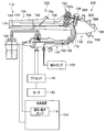
- FIG. 1 is a diagram showing an endoscope system
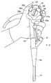
- FIG. 2 is an explanatory diagram when the operator operates the switch with the left hand held by the left hand
- FIG. FIG. 4 is a side view of the operation unit main body
- FIG. 5 is a cross-sectional view of main parts taken along line VV in FIG. 4
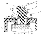
- FIG. 6 is a cross-sectional view of main parts taken along line VI-VI in FIG. 7 is an enlarged cross-sectional view of the main part of FIG. 5
- FIG. 8 is a perspective view showing the switch cover unit from the front side
- FIG. 9 is a perspective view showing the switch cover unit from the back side
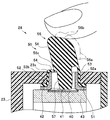
- FIG. FIG. 11 is a cross-sectional view of a main part showing a deformed state of the switch cover in response to a pressing operation from a substantially vertical direction.
- an endoscope system 1 includes an endoscope 2 that is an example of a handheld device, a light source device 3, a video processor 4 that is a CCU (camera control unit), and a monitor.
- the main part is comprised.
- the endoscope 2 includes an insertion portion 7 as an elongated hollow elongated member to be inserted into an observation target site, and an operation portion 8 connected to the proximal end portion of the insertion portion 7.
- the universal cable 9 extending from the side surface of the operation unit 8, the light source connector 10 provided at the extending end of the universal cable 9, and the electric cable 11 extending from the side of the light source connector 10
- an electrical connector 11 a disposed at the extending end of the electrical cable 11.
- the light source connector 10 is detachably connected to the light source device 3, and the electrical connector 11a is detachably connected to the video processor 4.
- the insertion portion 7 has a distal end portion 15 on the distal end side, and a bending portion 16 as a movable portion that can be bent is connected to the proximal end portion of the distal end portion 15. Further, a long and flexible flexible tube portion 17 formed of a flexible tubular member is connected to the base end portion of the curved portion 16.
- the operation unit 8 includes a bend preventing portion 20 connected to the proximal end side of the insertion portion 7, and a treatment instrument insertion port 21 that is disposed in the vicinity of the bend prevention portion 20 and communicates with a treatment instrument insertion channel in the insertion portion 7. And a gripping portion 22 disposed on the base side of the treatment instrument insertion port 21 and an operation portion main body 23 connected to the base end side of the gripping portion 22.
- the operation portion main body 23 is provided with a bending operation knob 25 for operating the bending portion 16 of the insertion portion 7.
- the bending operation knob 25 has a UD bending operation knob 25a for bending the bending portion 16 in the vertical direction and an RL bending operation knob 25b for bending the bending portion 16 in the left-right direction, which are coaxial. It is arranged so that it can rotate freely.
- a release knob 25c that is operated when stopping / releasing rotation of each of the bending operation knobs 25a and 25b is provided at the center of the RL bending operation knob 25b.
- the operation unit main body 23 includes, for example, an air / water supply cylinder 26 that communicates with a water supply tank (not shown), a suction cylinder 27 that communicates with a suction tank (not shown), and four push-type N switch devices. (Remote switches) 28 to 31 are provided.
- a detachable air / water supply button 26 a is attached to the air / water supply cylinder 26.
- a detachable suction button 27 a is attached to the suction cylinder 27.
- Each of the switch devices 28 to 31 is appropriately assigned with an image freeze function that freezes an endoscope image, a function that transmits image data to a printer, and various functions that adjust an endoscope image. .
- the air / water supply cylinder 26, the suction cylinder 27, and the three switch devices 28 to 30 are provided on one side portion on the side where the treatment instrument insertion port 21 is opened. Are arranged in a line along the longitudinal axis direction of the operation unit 8.
- the remaining one switch device 31 is disposed on the other side surface portion (the side surface portion opposite to the one side surface portion) on the side where the universal cable 9 extends.
- the light source device 3 supplies illumination light to a light guide (not shown) provided in the endoscope 2. That is, a light guide (not shown) is disposed in the universal cable 9, the operation unit 8, and the insertion unit 7 of the endoscope 2 according to the present embodiment, and the light source device 3 is provided via the light guide. Illumination light is supplied to an illumination optical system (not shown) constituting the illumination window of the tip 6. This illumination light is irradiated to the subject site by the illumination optical system.
- the light source device 3 is provided with the above-described water supply tank, and further includes a water supply pump (not shown) for supplying sterilized water from the water supply tank to the endoscope 2.
- the video processor 4 appropriately converts the image data captured by the endoscope 2 into a video signal based on the operation signals from the switch devices 28 to 31 and displays the image data on the monitor 5.
- an operator such as an operator usually holds the insertion portion 7 with the right hand and the operation portion 8 with the left hand.
- the gripping portion 22 is gripped from the side from which the universal cable 9 is extended to the middle finger, ring finger, and little finger of the left hand.
- the operator can mainly operate the air / water supply button 26a, the suction button 27a, and the switch devices 28 to 30 with the index finger of the left hand, and the switch device with the thumb. 31 can be operated.
- the switching devices 28 to 30 located far from the gripping portion 22 can be switched by not only the pressing operation from the vertical direction but also the pressing operation from the horizontal direction.
- the switch device 28 transmits to the switch substrate 40 a switch board 40 disposed in the operation unit main body 23 and external stress due to an operator's switch operation from outside the operation unit main body 23. And a switch cover 50 to be configured.
- the switch device 31 also has a switch board 40 similar to the switch devices 28 to 30, and further switches external stress due to an operator's switch operation from outside the operation unit body 23.
- a switch cover 65 for transmitting to the substrate 40 is provided.
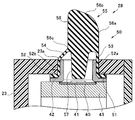
- the switch board 40 has, for example, a press-type normally-open switch part 41 that is superimposed on the board in a state where two contacts (not shown) are separated from each other.
- a switch opening 23a corresponding to the switch device 28 is provided on the side surface of the operation unit main body 23, and the switch substrate 40 is in a state where the switch unit 41 faces the switch opening 23a.
- the operation unit main body 23 is disposed substantially parallel to the inner wall surface.
- a washer 42 is provided between the switch board 40 and the operation unit main body 23 so as to be fitted into the switch opening 23a via the switch cover 50.
- the switch board 40 includes the washer 42 and the operation unit main body 23.
- the support member 43 is fixed between the support member 43 and the support member 43. Accordingly, the switch substrate 40 is held in the operation unit main body 23, and the switch unit 41 can perform a switching operation by an external stress having a component perpendicular to the outer surface of the operation unit main body 23 (operation unit 8). It has become.
- the switch cover 50 includes, for example, a flat plate-like base portion 51, a cylindrical portion 52 erected from the base portion 51, and a first deformation portion 53 and a second deformation portion that are connected to an end portion of the cylindrical portion 52.
- the switch covers 50 of the switch devices 28 to 30 are connected to each other via the base 51 and further connected to the switch cover 65 of the switch device 31.
- the parts 66 are connected to each other. That is, in the present embodiment, each switch cover 50 of the switch devices 28 to 30 and the switch cover 65 of the switch device 31 are constituted by an integral resin molded product or the like.
- the cylindrical portion 52 is mainly composed of a cylindrical body in which a plane portion 52 a and a curved surface portion 52 b are combined.
- the cylindrical portion 52 is interposed between the switch opening 23 a of the operation portion main body 23 and the washer 42 while surrounding the switch portion 41.
- the cylindrical part 52 extends in the direction substantially perpendicular to the outer surface of the operation part main body 23 over the inside and outside of the operation part main body 23.
- the first deforming portion 53 is connected to a partial region in the circumferential direction of the cylindrical portion 52 outside the operation portion main body 23. More specifically, in the present embodiment, the first deformable portion 53 is formed by a flat portion that is continuous with the flat portion 52 a of the tubular portion 52.
- the second deformation portion 54 is provided outside the operation portion main body 23 in a region other than the first deformation portion 53 in the circumferential direction of the tubular portion 52. More specifically, in the present embodiment, the second deformable portion 54 is formed by a tapered surface portion that is continuous with the curved surface portion 52 b of the cylindrical portion 52. That is, in contrast to the first deformable portion 53 configured by a surface portion that extends without substantially inclining with respect to a direction perpendicular to the outer surface of the operation portion main body 23, the second deformable portion 54 is provided on the outer surface of the operation portion main body 23.
- the second deformation portion 54 is configured by a surface portion that is inclined at a predetermined elevation angle toward the first deformation portion 53 side. And, by inclining in this way, a stepped shape is formed between the second deformable portion 54 and the tubular portion 52 (curved surface portion 52b), whereby the second deformable portion 54 It is possible to deform more easily than the first deforming portion 53.
- the region where the second deformation portion 54 is formed is longer than the region where the first deformation portion 53 is formed. It is set in the area.
- the stress transmission unit 55 includes a protruding operation input unit 56 that is continuous with the ends of the first and second deformation units 53 and 54, and an input to the operation input unit 56. And a pressing portion 57 that transmits the external stress applied to the switch portion 41.
- the operation input unit 56 is formed of a solid member having a substantially triangular prism shape whose cross-sectional area in the inner peripheral direction is relatively smaller than the cross-sectional area in the inner peripheral direction of the cylindrical part 52, for example.
- one plane is set as a first pressed surface 56a capable of inputting external stress due to the operator's pressing.
- the first pressed surface 56 a constitutes the same plane as the flat portion 52 a of the cylindrical portion 52 and the first deformable portion 53. That is, in the present embodiment, the operation input unit 56 is arranged offset to the first deforming unit 53 side with respect to the center of the cylindrical portion 52, whereby the first pressed surface 56 a is cylindrical.
- the flat portion 52 a of the portion 52 and the first deformable portion 53 are arranged flush with each other.
- the top surface of the operation input unit 56 is set as a second pressed surface 56b capable of inputting external stress due to the operator's pressing.
- the second pressed surface 56b is formed by an inclined surface having a predetermined elevation angle from the first deformable portion 53 side to the second deformable portion 54 side.
- the first It is possible to generate a stress component in a direction perpendicular to the pressed surface 56a.
- the remaining two planes are connected to the end of the second deformable section 54 with a predetermined angle.
- the corner-shaped portion 56 c formed by the remaining two planes of the operation input portion 56 faces substantially the center of the end portion of the second deformable portion 54.
- the pressing portion 57 is composed of a rod-shaped member provided integrally with the base end portion of the operation input portion 56.
- the pressing portion 57 is disposed in a space formed by the cylindrical portion 52 and the first and second deformable portions 53 and 54, and is disposed so as to face the position where the tip portion can contact and separate from the switch portion 41. ing.
- the pressing part 57 of this embodiment is integrally formed with the operation input part 56, the pressing part 57 which consists of another member is integrally fixed to the base end part of the operation input part 56, for example. It may be the configuration.
- the operation input unit 56 is mainly operated.
- An external stress in the horizontal direction is input to the outer surface of the body part 23.
- the second deformable portion 54 that is easier to deform than the first deformable portion 53 starts buckling deformation starting from the stepped shape with the cylindrical portion 52 (curved surface portion 52b).
- the first deformable portion 53 starts bending deformation toward the second deformable portion 54 side (inside the cylindrical portion 52).
- the operation input unit 56 tilts in the direction of the second deformation unit 54 due to the deformation of the first and second deformation units 53 and 54. That is, since the deformation of the second deformation portion 54 is a buckling deformation, and the deformation of the first deformation portion 53 is a bending deformation, the operation input unit 56 uses the first deformation portion 53 as a fulcrum. Tilt in the direction of the second deformable portion 54.
- the switch unit 41 As the operation input unit 56 is tilted, the end of the pressing unit 57 is brought into contact with the switch unit 41, and stress having a component perpendicular to the outer surface of the operation unit main body 23 is transmitted to the switch unit 41. As a result, two contacts (not shown) of the switch unit 41 are electrically connected, and the switch device 28 is turned on.
- the operation input unit 56 When the first pressed surface 56a is released from the pressing, the operation input unit 56 is erected by the restoring force of the first and second deforming units 53 and 54, and accordingly, the switch device 28 is turned off.
- the operation input unit 56 tilts in the direction of the second deformation unit 54 due to the deformation of the first and second deformation units 53 and 54. That is, since the deformation of the second deformation portion 54 is a buckling deformation, and the deformation of the first deformation portion 53 is a bending deformation, the operation input unit 56 uses the first deformation portion 53 as a fulcrum. Tilt in the direction of the second deformable portion 54.
- the switch unit 41 As the operation input unit 56 is tilted, the end of the pressing unit 57 is brought into contact with the switch unit 41, and stress having a component perpendicular to the outer surface of the operation unit main body 23 is transmitted to the switch unit 41. As a result, two contacts (not shown) of the switch unit 41 are electrically connected, and the switch device 28 is turned on.
- the first deformable portion 53 that is connected to the flat surface portion 52a of the tubular portion 52 disposed so as to surround the switch portion 41 and deforms due to external stress
- the tubular portion 52, the second deformable portion 54 connected to the curved surface portion 52b and deformed by the external stress
- the first deformable portion 53 connected to the first and second deformable portions 53, 54 by the external stress.
- the second deformation portion 54 by forming the second deformation portion 54 by an inclined portion (tapered surface portion) that is inclined at a larger angle than the first deformation portion 53 with respect to the direction perpendicular to the outer surface of the operation portion main body 23,
- the second deformable portion 54 can be buckled and deformed with respect to external stress.
- the first and second deformable portions 53 and 54 are formed with the same thickness, the second deformable portion 54 is formed. Can be more easily deformed than the first deformable portion 53.
- the stepped shape is formed with the cylindrical portion 52 (curved surface portion 52b) by the inclination of the second deformable portion 54, the second deformable portion 54 can be buckled and deformed more effectively. .
- the operation input unit 56 is formed in a substantially triangular prism shape, and the two planar corner portions 56 c constituting the peripheral surface of the operation input unit 56 are made to face the end of the second deforming unit 54. It can function as a stress concentration part that concentrates external stress on a part of the second deformable part 54, and the second deformable part 54 can be buckled and deformed more accurately when external stress is input.
- the cross-sectional area of the operation input unit 56 is set to a cross-sectional area smaller than the cross-sectional area of the cylindrical part 52, and the operation input part 56 is offset toward the first deformable part 53 side with respect to the center of the cylindrical part 52. By disposing them, it is possible to set a relief area when the second deformable portion 54 is buckled and to more accurately buckle deform the second deformable portion 54.
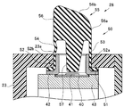
- the present invention is not limited to this, for example, as shown in FIG.
- the second deformable portion 54 is configured to be more easily deformed than the first deformable portion 53 by configuring the second deformable portion 54 with an inclined surface portion.
- the second deformation portion 54 is formed to be relatively thinner than the first deformation portion 53, so that the second deformation portion 54 is formed.
- the part 54 may be configured to be deformed more easily than the first deforming part 53.
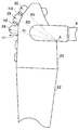
- the operation part 8 of the endoscope 2 is grasped with the left hand, and the operation is performed by placing the root part A of the part where the universal cable 9 is attached to the operation part main body 23 on the crotch part of the thumb and forefinger.
- the distances R1 to R3 from the root A to the apexes of the switch devices 28 to 30 are configured to be equal to each other. It is also possible.
- the plurality of switch devices 28 to 30 can be pushed out with ease by one index finger without changing the gripped hand (without re-gripping).
- the switch devices 28 to 30 may be arranged so that the distances H1 to H3 are not constant (for example, H1> H2> H3).
- handheld devices to which the switch cover and the switch device of the present invention are applied are not limited to endoscopes, and can be applied to various handheld devices that perform switch operations with a hand while holding the operation unit.
- handheld devices to which the switch cover and the switch device of the present invention are applied are not limited to endoscopes, and can be applied to various handheld devices that perform switch operations with a hand while holding the operation unit.
- endoscopes can be applied to various handheld devices that perform switch operations with a hand while holding the operation unit.
- Japanese Patent Application Laid-Open No. 8-191789 discloses a plurality of electronic button switches (pressing units) such as a release button. It is disclosed that it is arrange
- Each of these button switches has a switch member in which a switch body is built and an operation member that is touched by an operator's finger.
- the operation member has a pedestal integrally formed at the bottom of a substantially cylindrical rubber cover. Two prismatic engaging portions are formed in the lower portion of the base toward the inside of the operation portion. These engaging portions are engaged with locking holes at the peripheral edge portion of the switch mounting hole formed in the outer case of the operation portion.
- the switch base of the switch member, the switch receiver, and the engaging portion are fixed by screws with fixing screws.
- button switches pressing portions
- button switches are separately attached to the exterior case.
- the second embodiment of the present invention has been made to solve such a problem, and an object thereof is to provide an endoscope in which the assembling property of the pressing portion with respect to the operation portion is improved.
- the endoscope according to the second embodiment includes an operation unit that is operated while being held by a user's hand, and an insertion unit that extends from the operation unit and is inserted into a tube hole.
- the operation unit has first and second inner peripheral surfaces facing each other and a plurality of openings disposed on at least one of the first and second inner peripheral surfaces, and is gripped by the user's hand.
- a flexible outer casing, and a plurality of elastically deformable pressing portions protruding from the inner side to the outer side of the outer casing through the opening, and arranged along the first and second inner peripheral surfaces of the outer casing.
- a plate is disposed on the inner side of the flexible plate along the first and second inner peripheral surfaces of the outer case, and supports the pressing portion of the flexible plate between the outer case and the flexible plate. Liquid invades Holding a substrate having a plate-shaped intermediate member to be prevented and a switch that can be switched between a position pressed by the pressing portion and a position released from the pressing portion at a position facing the pressing portion; The intermediate member and the intermediate member press the flexible plate toward the first and second inner peripheral surfaces of the outer case to bring the intermediate member into close contact with the flexible plate, and the flexible plate is attached to the first plate. And a holder that is in close contact with the second inner peripheral surface and supported inside the outer case.
- an endoscope having an operation part that can use a plurality of pressing parts by simply attaching three members, a flexible plate having a plurality of pressing parts, an intermediate member, and a holder holding a substrate to the exterior case. Can do. For this reason, the assemblability of the switch portion can be greatly improved.
- an intermediate member is disposed between the flexible plate and the holder to support the pressing portion and prevent liquid from entering between the exterior case and the flexible plate. For this reason, while preventing excessive deformation of the pressing portion, the function of preventing the liquid from entering between the outer case and the flexible plate has two functions of the flexible plate and the intermediate member with the holder for the outer case. This can be achieved by pressing.
- the intermediate member has an annular edge that holds the pressing portion of the flexible plate facing the substrate held by the holder, and faces the annular edge and the annular edge.
- the flexible plate has an annular engagement portion that is provided on a base portion of the pressing portion and engages with each other to restrict deformation of the base portion of the pressing portion.
- the surface of the flexible plate and the inner peripheral surface of the outer case are brought into close contact with at least one of the inner peripheral surface of the outer case, the front or back surface of the flexible plate, and the surface of the intermediate member. It is preferable to have an annular convex portion for achieving watertightness. By forming an annular convex portion on at least one of the inner peripheral surface of the outer case, the front or back surface of the flexible plate, and the surface of the intermediate member, water tightness between the outer case and the flexible plate is improved. , Can prevent the liquid from entering.
- the intermediate member is made of a material harder than the flexible plate, and is made of a material more flexible than the exterior case and the holder.
- the holder is designed to be softer than the intermediate member, softer than the intermediate member, and harder than the flexible plate and intermediate member. And pressing. For this reason, when arrange
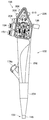
- the endoscope system 110 includes an endoscope 112, a light source device 114 having an air / water supply pump 116, a processor 118, a monitor 120, a suction pump 122, and a water supply tank 124. .
- the endoscope 112 includes an operation unit 132 that is operated while being held by a user's hand, and an insertion unit 134 that extends from the operation unit 132 and is inserted into a lumen such as a body cavity. And have.
- a universal cable 136 is extended from the operation unit 132.
- a light source device 114, a processor 118, a suction pump 122, and a water supply tank 124 are connected to the extended end of the universal cable 136.
- the insertion part 134 includes a distal end hard part 142, a bending part 144, and a soft or hard tubular part 146.
- the distal end of the known illumination optical system and the observation optical system is arranged on the distal end hard portion 142, and for example, an observation object such as a living body can be illuminated and observed.
- the bending portion 144 can bend the distal end of the insertion portion 134 in a desired direction using a known bending mechanism by rotating a bending operation knob (not shown) disposed in the operation portion 132.
- the operation unit 132 is provided with an air / water supply button 152, a suction button 154, and a plurality of electric switches 156.
- the air / water supply button 152 is a part of a known air / water supply mechanism.
- the air supply tube 162 is connected to the air / water supply pump 116 shown in FIG. 15 through the leak hole 152a of the air / water supply button 152 to the outside air. It is inserted. For this reason, air is not supplied to the air supply tube 164. In this state, the air supply tube 162 and the water supply tank 124 are shut off. For this reason, in the non-operation state, neither air supply nor water supply is performed from the distal end of the insertion portion 134.
- the leak hole 152a is closed with a finger without pressing the air / water supply button 152, the leak hole 152a is closed, so that the air supply tube 162 is communicated with the air supply tube 164. Therefore, the air supplied to the air supply tube 162 flows into the air supply tube 164 and is supplied (air is discharged) from the distal end of the insertion portion 134.
- the water supply tube 166 and the water supply tube 168 are communicated. In this state, the air supply tube 162 and the air supply tube 164 are blocked. Accordingly, since the air supply tube 162 is blocked from other pipes, the air supplied from the air / water supply pump 116 is supplied onto the liquid level of the water supply tank 124.
- the internal pressure of the water supply tank 124 increases, and the physiological saline in the water supply tank 124 is supplied to the water supply tube 166. Therefore, the physiological saline flows from the water supply tube 166 to the water supply tube 168, and is fed from the distal end of the insertion portion 134 (the physiological saline is discharged).
- the operation unit 132 is fixed to a gripping part (grip) 202 that is gripped by a user, and a bend preventing the base end of the insertion part 134 from being buckled by fixing the base end of the insertion part 134.
- a gripping part (grip) 202 that is gripped by a user, and a bend preventing the base end of the insertion part 134 from being buckled by fixing the base end of the insertion part 134.
- 204 and an air / water supply button 152, a suction button 154, and a switch unit 206 in which a plurality of electric switches 156 are arranged in parallel.
- the switch unit 206 is disposed at a distal end with respect to the tip of the insertion unit 134.
- a forceps plug 174a disposed in the gripper 202 is disposed at the proximal end of a treatment instrument insertion channel 174 (see FIG.
- the above-described air / water supply button 152 for switching the air / water supply in the air / water supply mechanism, the above-described suction button 154 for switching the suction in the suction mechanism, and a plurality of electric switches 156. are disposed in an exterior case 212 (to be described later) of the switch unit 206 of the operation unit 132.
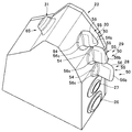
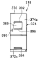
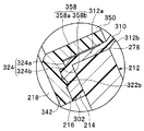
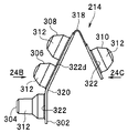
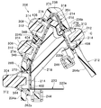
- the switch unit 206 includes an exterior case 212, a flexible plate 214, a plate-like intermediate member 216, and a holder 218 that holds the substrate 220 of the electric switch 156.
- the outer case 212 is detachable from the grip 202 shown in FIG. 16 and is fixed in a watertight manner. It is also preferable that the outer case 212 is formed integrally with the grip portion 202.
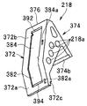
- the outer case 212 shown in FIGS. 18A to 18E is formed of a hard material having heat resistance, chemical resistance and insulation, such as modified PPE (polyphenylene ether).
- the exterior case 212 includes a base 232 that can be attached to and detached from the gripper 202, and first and second case side portions 234 and 236 that are integrally extended from the base 232.
- the first and second case side portions 234 and 236 are integrally connected by a top portion 238 facing the base portion 232. That is, the base portion 232, the first and second case side portions 234, 236, and the top portion 238 cooperate to form a substantially cylindrical shape.
- the base 232 is formed with an opening 232a through which the above-described tubes 164, 168, 174 (see FIG.
- an electric cable (not shown) of the electric switch unit 156, and the like are passed.
- an imaging element of the observation optical system is electrically connected to an insertion unit side electric cable (not shown) of the electric switch unit 156.
- an opening (not shown) through which the base end of the universal cable 136 is connected to the second case side part 236 through the tubes 162, 166, 172 (see FIG. 15), an electric cable (not shown) of the electric switch unit 156, or the like. Is formed.
- a peripheral device electrical cable (not shown) of the electrical switch unit 156 is electrically connected to peripheral devices such as the light source device 114 and the processor 118.
- the opening for fixing the universal cable 136 is preferably formed in, for example, a second case standing portion 236a described later of the second case side portion 236.
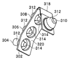
- the first case side part 234 includes a first case standing part 234a standing substantially perpendicular to the base part 232, and a first case inclined toward the top part 238 from the first case standing part 234a. And a slope portion 234b.
- the second case side part 236 includes a second case standing part 236a standing substantially perpendicular to the base part 232, and a second case inclined toward the top part 238 from the second case standing part 236a. And an inclined surface portion 236b.
- the width of the exterior case 212 is gradually increased by the first and second case slope portions 234b and 236b from the base portion 232 toward the top portion 238 along the first and second case side portions 234 and 236. It is preferable to be formed to be small.
- a bottom portion 242 as a side wall of the exterior case 212 is integrally formed with a substantially cylindrical portion formed by the base portion 232, the first and second case side portions 234, 236, and the top portion 238.
- Two pillars (first and second pillars) 244 and 246 that hold the holder 218 in a predetermined position are formed in the bottom portion 242 so as to extend toward the opening 250 of the substantially cylindrical portion described above. ing.
- the cross sections of the columns 244 and 246 are formed in a rectangular shape in this embodiment, but may have various shapes such as a circle.
- a lid member 252 shown in FIG. 18D is fixed in a watertight state to the opening 250 of the substantially cylindrical portion.
- the inner peripheral surface 262a of the first case standing portion 234a and the inner peripheral surface 264a of the second case standing portion 236a face each other.
- the inner peripheral surfaces 262a and 264a are preferably parallel, for example.
- the inner peripheral surface (first inner peripheral surface) 262b of the first case slope portion 234b and the inner peripheral surface (second inner peripheral surface) 264b of the second case slope portion 236b are, for example, substantially V-shaped. Are inclined at an appropriate angle so as to face each other.
- an acute angle, a right angle, or an obtuse angle may be sufficient between the 1st case slope part 234b and the 2nd case slope part 236b. In this embodiment, description will be made assuming that the angle is acute.
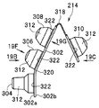
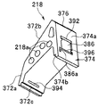
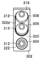
- the first case standing part 234a has a first electric switch opening 272 in which one pressing part 304 formed integrally with the flexible plate 214 is disposed.
- the first case slope 234b has second and third electrical switch openings 274 and 276 in which two pressing portions 306 and 308 formed integrally with the flexible plate 214 are disposed.
- the second case inclined surface portion 236b has a fourth electric switch opening 278 in which one pressing portion 310 formed integrally with the flexible plate 214 is disposed.
- the first electrical switch opening 272 is adjacent to the second electrical switch opening 274.
- the first case standing portion 234a has an air / water supply button opening 282 in which the air / water supply button 152 is disposed, and a suction button opening 284 in which the suction button 154 is disposed.
- openings 272, 274, 276, 282, and 284 are formed in the first case side part 234, and among these, the base part 232 is arranged side by side on the side close to the top part 238.
- the flexible plate 214 shown in FIGS. 19A to 19E is made of a soft resin material having heat resistance and insulation properties such as a silicone resin material. That is, the flexible plate 214 is a material that is sufficiently soft with respect to the exterior case 212.
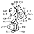
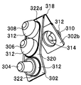
- the flexible plate 214 includes a soft plate portion 302 and four pressing portions (first to fourth pressing portions) 304, 306, 308, 310 in this embodiment.
- the pressing portions 304, 306, 308, and 310 protrude toward the surface 302 a side of the soft plate portion 302.
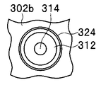
- the pressing portions 304, 306, 308, and 310 are convex portions that are formed integrally with the soft plate portion 302 and have a base portion 312 a and are integrally formed with the deformed portion 312 b of the button portion 312 and face the substrate 220. Part 314.
- the button 312 includes first to fourth collars 344, 346, 348, 350 and first to fourth electrical switch openings 272, 274, 276, 278, which will be described later, respectively.
- Each pressing portion 304, 306, 308, 310 is preferably formed so as to give a click feeling to the operator when pressed.
- the pressing portions 304, 306, 308, and 310 may all have the same shape or different shapes.
- the first pressing portion 304 adjacent to the suction button 154 shown in FIG. 15 is shaped differently from the other pressing portions (second to fourth pressing portions) 306, 308, 310 having the same shape. Forming.
- the surface 302a of the soft plate portion 302 is formed by the inner peripheral surface 262a of the first case standing portion 234a of the outer case 212, the inner peripheral surface 262b of the first case inclined surface portion 234b, and the inner periphery of the second case inclined surface portion 236b. It can be in close contact with the surface 264b.
- the soft plate portion 302 can be easily bent.
- the bent portion 318 is preferably formed.
- the bent portion 318 is preferably formed by making it thin, but a material having higher flexibility than other portions of the soft plate portion 302 may be used.
- a portion (boundary) corresponding to the first case standing portion 234a and the first case slope portion 234b has a foldable bending portion 320. Since the first inclined surface portion 234 b is formed at an obtuse angle with respect to the inclination angle between the inner peripheral surface 262 b of the second inclined surface portion 236 b and the inner peripheral surface 264 b of the second inclined surface portion 236 b, the bent portion 320 is flexible to the flexible plate portion 302. Depending on the nature, it is possible to bend easily without processing such as thin wall.
- the flat inner peripheral surfaces 262 a, 262 b of the outer case 212 are positioned at the protruding direction side (surface 302 a side) of the pressing portions 304, 306, 308, 310. , 264b, an annular protrusion 322 shown in FIGS. 19A to 19F is formed. Since the soft plate portion 302 of the flexible plate 214 tries to return straight due to the elastic force when it is bent from the state shown in FIGS. 19A to 19E, it is easy to maintain the fitting state with respect to the outer case 212.
- each button portion 312 it is the boundary between the soft plate portion 302 and the button portion 312 in the base portion 312a of each button portion 312, and the position opposite to the protruding direction of each pressing portion 304, 306, 308, 310 (the back surface 302b side).
- the annular recess 324 is preferably formed so as to have a rectangular corner as much as possible.
- annular convex part 358 is formed at the same angle so that it may mutually contact
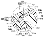
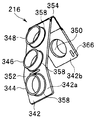
- the intermediate member 216 shown in FIGS. 20A to 20F is formed in a substantially rectangular shape with a hard resin material having heat resistance and insulation, such as polypropylene.
- the intermediate member 216 is formed of a material harder than the flexible plate 214 and is formed of a softer material than the exterior case 212.
- the intermediate member 216 includes a rigid plate portion 342 and cylindrical collars (first to fourth collars) 344, 346, 348, as four annular edges in this embodiment. 350.
- One side (surface) 342a of the hard plate portion 342 is flexible between the first case standing portion 234a, between the first case slope portion 234b, and between the second case slope portion 236b.
- the soft plate portion 302 of the plate 214 is pressed.
- the hard plate portion 342 of the intermediate member 216 presses the inside of the soft plate portion 302 of the flexible plate 214 toward the outside.
- a portion (boundary) corresponding to the first case standing portion 234 a and the first case slope portion 234 b has a first bent portion 352 that can be bent.
- a portion (boundary) corresponding to the first case slope portion 234b and the second case slope portion 236b has a second bendable portion 354 that can be folded.
- the first and second bent portions 352 and 354 are formed, for example, by thinning.
- the first collar 344 supports the inner peripheral surface of the button portion 312 of the first pressing portion 304 of the flexible plate 214 between the first electric switch opening 272 of the exterior case 212.
- the second collar 346 supports the inner peripheral surface of the button portion 312 of the second pressing portion 306 of the flexible plate 214 between the second electric switch opening 274 of the exterior case 212.
- the third collar 348 supports the inner peripheral surface of the button portion 312 of the third pressing portion 308 of the flexible plate 214 between the third electric switch opening 276 of the exterior case 212 and the fourth collar 350 is flexible.
- the inner peripheral surface of the button portion 312 of the fourth pressing portion 310 of the plate 214 is supported between the fourth electric switch opening 278 of the exterior case 212.
- the first to fourth collars 344, 346, 348, 350 sandwich the base 312a of the button portion 312 between the first to fourth electrical switch openings 272, 274, 276, 278.
- annular convex portion 358 shown in FIG. 20F is formed, into which the annular concave portion 324 (see FIG. 19G) of the flexible plate 214 is fitted. Yes.
- the annular convex portion 358 is preferably formed to have a rectangular corner portion as much as possible so as to fit into the annular concave portion 324.
- the other side surface (back surface) 342b of the hard plate portion 342 of the intermediate member 216 is provided with convex portions (engagement portions) 382a, 384a, and 386a of the holder 218 (FIGS. 21A to 21E).
- Recessed portions (engagement portions) 362, 364, and 366 are formed, respectively. These concave portions (engagement portions) 362, 364, and 366 are separated from the bottom portion 242 (see FIGS. 18A, 18D, and 18E) of the outer case 212 in a state where the intermediate member 216 is disposed in the outer case 212, and the opening 250. It is preferable that it is formed on the side close to.
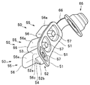
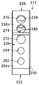
- the holder 218 shown in FIGS. 21A to 21E is formed of a hard resin material having heat resistance and insulating properties such as polypropylene.
- the holder 218 is formed of a material that is harder than the flexible plate 214 and the intermediate member 216, and is formed of a material similar to the hardness of the outer case 212. That is, the outer case 212 and the holder 218 may have the same hardness, the outer case 212 may be harder than the holder 218, or the outer case 212 may be softer than the holder 218.
- the outer periphery of the holder 218 is formed in a shape corresponding to the side of the first and second case side portions 234 and 236 of the outer case 212 that is close to the top portion 238.
- the holder 218 has first and second holder side portions (holder outer peripheral surfaces) 372 and 374.
- the first and second holder side portions 372 and 374 are integrally connected by a top portion 376.
- the holder 218 may be formed in a substantially V shape having the first and second holder side portions 372 and 374 depending on the selection of the material, but the first and second case sides of the outer case 212
- a block shape having an integral material in the portion between them
- a plurality of circular holes 218a are formed in a portion between the first and second holder side portions 372 and 374. It is preferable to do.
- the first holder side portion 372 includes a first holder standing portion 372a along the first case standing portion 234a and a top portion 376 from the first holder standing portion 372a along the first case slope portion 234b. And a first holder inclined surface portion 372b inclined toward the surface.
- the second holder side portion 374 has a second holder slope portion 374a along the second case slope portion 236b.
- the angle formed by the slope portions 372b and 374a of the first and second holder side portions 372 and 374 is the same as the angle formed by the inner peripheral surfaces 262b and 264b of the first and second case slope portions 234b and 236b of the exterior case 212. Or substantially the same.
- the first holder standing portion 372a is formed with a first fitting portion 372c into which the first column 244 of the outer case 212 is fitted, and the second holder inclined surface portion 374a has an outer case.
- a second fitting portion 374b into which the second pillar 246 of 212 is fitted is formed.
- the first case sloped portion 234b and the first case inclined portion 234b are arranged between the first case standing portion 234a and the first holder standing portion 372a.
- a slight gap is formed between the first holder slope 372b and between the second case slope 236b and the second holder slope 374a.
- the size of the gap is slightly smaller than the total thickness of the soft plate portion 302 of the flexible plate 214 and the hard plate portion 342 of the intermediate member 216.
- the first column 244 of the outer case 212 applies the force of the first holder side portion 372 of the holder 218 to the inner peripheral surface 262a and the first case inclined surface portion 234b of the first case standing portion 234a of the outer case 212.
- the inner casing 262b has a surface facing the first case standing portion 234a and a surface facing the first case slope portion 234b.
- the second column 246 of the outer case 212 is configured so that the second column 246 of the outer case 212 exerts the force of the second holder side portion 374 of the holder 218 on the inner peripheral surface 264b of the second case inclined surface 236a. It has a surface facing the portion 236b.
- the second column 246 has a surface directed toward the top 238 so as to exert the force of the second holder side 374 of the holder 218 toward the top 238 of the outer case 212. Therefore, the holder 218 can press the intermediate member 216 and the flexible plate 214 against the inner peripheral surfaces 262a, 262b, 264b of the outer case 212.
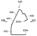
- the substrate 220 shown in FIGS. 22A and 22E is preferably formed in a flexible strip shape, for example, of a polyimide resin material or a polyethylene resin material.
- the substrate 220 is wound around the holder 218 and attached. That is, the holder 218 is used to hold the substrate 220 while pressing the intermediate member 216 and the flexible plate 214 against the inner peripheral surfaces 262a, 262b, and 264b of the outer case 212.
- the first holder side portion 372 of the holder 218 includes a first holding surface 382 formed in a concave shape on the first holder standing portion 372a and a first holder formed continuously with the first holding surface 382. And a second holding surface 384 formed in a concave shape on the slope portion 372b.
- the second holder side portion 374 of the holder 218 has a third holding surface 386 formed in a concave shape on the first holder inclined surface portion 372b.
- the second holding surface 384 and the third holding surface 386 communicate with each other through a communication path 392 inside the holder 218.
- a first guide path 394 that directs one end 220a of the substrate 220 toward the inside of the holder 218 is formed at the end of the first holding surface 382 (the end on the side separated from the top 376).
- a second guide path 396 that makes the other end 220 b of the substrate 220 face the inside of the holder 218 is formed at the end of the holding surface 386 (the end on the side separated from the top 376).
- the first holder upright portion 372 a, the first holder slope portion 372 b, and the second holder slope portion 374 a of the holder 218 are provided on the back surface of the hard plate portion 342 of the intermediate member 216.
- Convex portions (engaging portions) 382a, 384a, and 386a are formed into which the concave portions (engaging portions) 362b, 364, and 366 (see FIG. 20C to FIG. 20E) of 342b are respectively fitted.
- These convex portions 382a, 384a, and 386a are formed on the side that is separated from the bottom portion 242 of the outer case 212 (see FIGS. 18A, 18D, and 18E) and close to the opening 250 with the holder 218 disposed on the outer case 212. It is preferable that
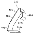
- the first switch 402 of the substrate 220 is provided on the first holding surface 382, and the second and third of the substrate 220 are provided on the second holding surface 384.
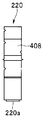
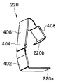
- the switches 404 and 406 and the fourth switch 408 of the substrate 220 are disposed on the third holding surface 386.
- the substrate 220 is arranged on the holder 218 so as not to protrude from the first holder side portion 372 of the holder 218 even at the boundary portion between the first holding surface 382 and the second holding surface 384 due to the flexibility of the substrate 220.
- the substrate 220 is wound around the holder 218.
- a flexible plate 214 is attached to the outer case 212.
- the first pressing portion 304 of the flexible plate 214 is inserted into the first electric switch opening 272 of the outer case 212
- the second pressing portion 306 is similarly inserted into the second electric switch opening 274, and the third electric switch.
- the third pressing portion 308 is attached to the opening 276, and the fourth pressing portion 310 is attached to the fourth electric switch opening 278.
- the annular protrusion 322 of the flexible plate 214 is brought into contact with the inner peripheral surfaces 262a, 262b, 264b of the outer case 212.
- the intermediate member 216 is attached to the flexible plate 214 in this state.
- the first collar 344 of the intermediate member 216 is applied to the first pressing portion 304 of the flexible plate 214
- the second collar 346 is similarly applied to the second pressing portion 306, and the third pressing portion 308 is applied to the third pressing portion 308.
- the fourth collar 350 is attached to the fourth pressing portion 310.
- the annular convex portion 358 of the intermediate member 216 is fitted into the annular concave portion 324 of the flexible plate 214.
- the collars 344, 346, 348, 350 of the intermediate member 216 are connected to each other by the plate portion 342 and are not separated, movement in the circumferential direction is restricted.
- the concave portions (engaging portions) 362, 364, and 366 of the plate portion 342 of the intermediate member 216 are located closer to the opening 250 of the outer case 212 than the bottom portion 242 of the outer case 212.
- the holder 218 around which the substrate 220 is wound is disposed so as to press the intermediate member 216 and the flexible plate 214 against the inner peripheral surfaces 262a, 262b, 264b of the outer case 212.
- the convex portions (fitting portions) 382a, 384a, 386a of the holder 218 are fitted and engaged with the concave portions (fitting portions) 362, 364, 366 of the plate portion 342 of the intermediate member 216.
- the holder 218 is pressed against the intermediate member 216 by the columns 244 and 246, and the flexible plate 214 is pressed against the inner peripheral surfaces 262 a, 262 b, and 264 b of the outer case 212 by the intermediate member 216.
- the convex portion 314 of the first pressing portion 304 is disposed inside the first collar 344 and faces the first switch 402, and the convex portion of the second pressing portion 306.
- 314 is disposed inside the second collar 346 and faces the second switch 404
- the convex portion 314 of the third pressing portion 308 is disposed inside the third collar 348 and is connected to the third switch 406.
- the convex part 314 of the fourth pressing part 310 is arranged inside the fourth collar 350 and faces the fourth switch 408. For this reason, for example, when the button unit 312 of the first pressing unit 304 is pressed, the first switch 402 is switched, and an appropriate operation that can be set by the processor 118 can be performed.
- the first switch 402 can be used as a release switch for an observation image of the endoscope 112.
- the first to fourth switches 402, 404, 406, and 408 can be set as appropriate, such as freeze, image recording, image printing, and a switch for switching to observation using light different from observation using white light.
- the switches 402, 404, 406, and 408 can be set in accordance with the use state by a known means provided in the processor 118, for example. Note that the opening 250 of the exterior case 212 is sealed with a lid member 252 shown in FIG. 18D.
- the holder 218 around which the flexible plate 214, the intermediate member 216, and the substrate 220 are wound around the exterior case 212 can be fixed at a predetermined position without using a screw or an adhesive.
- the switch portion 206 can be formed only by a simple assembling operation of simply placing the cover on the exterior case 212.
- the annular protrusion 322 of the surface 302a of the flexible plate portion 302 of the flexible plate 214 is in close contact with the inner peripheral surfaces 262a, 262b, 264b of the exterior case 212, and the annular protrusion 322 of the flexible plate 214 is elastically deformed. It plays a role like an O-ring. For this reason, it is possible to prevent liquid such as water from entering between the button portion 312 of the flexible plate 214 and the inner peripheral surfaces 262a, 262b, 264b of the outer case 212.
- the endoscope 112 can withstand cleaning, high-pressure steam sterilization, and the like performed to reuse the endoscope 112. Further, the annular concave portion 324 of the flexible plate 214 and the annular convex portion 358 of the intermediate member 216 are fitted in a shape having a rectangular corner as much as possible.
- the annular concave portion 324 and the annular convex portion 358 are both the surfaces 324a and 358a parallel to the soft plate portion 302 of the flexible plate 214 and the hard plate portion 342 of the intermediate member 216, and the surfaces 324b and 358b perpendicular to each other. It is closely attached. Therefore, the annular recess 324 and the annular projection 358 can be brought into close contact with the two annular surfaces. Even if one button portion 312 is pressed or pulled and deformed, the other button portions 312 can hold the same position in the same shape.
- the corner formed by the electrical switch opening 278 of the exterior case 212 and the inner peripheral surface (second inner peripheral surface) 264b of the second case sloped surface 236b, and the flexible plate 214 The distance ⁇ between the corner formed by the plane 324 a parallel to the soft plate 302 and the vertical plane 324 b is formed smaller than the thickness ⁇ of the soft plate 302 of the flexible plate 214.
- the convex portions (fitting portions) 382a, 384a, 386a of the holder 218 are engaged with and engaged with the concave portions (fitting portions) 362, 364, 366 of the plate portion 342 of the intermediate member 216. For this reason, it is possible to prevent displacement of the plate portion 342 of the intermediate member 216 from the holder 218 to the opening 250 side or the bottom surface 242 side of the exterior case 212. In addition, it is possible to prevent displacement of the plate portion 342 of the intermediate member 216 in the longitudinal direction with respect to the holder 218.
- the collars 344, 346, 348, 350 of the intermediate member 216 are connected to each other by the plate portion 342 and are not separated, movement in the circumferential direction around the central axis C (see FIG. 17A) is restricted.
- the collars 344, 346, 348, and 350 can be rotated in the circumferential direction around the central axis C by preventing the displacement of the plate portion 342 of the intermediate member 216 relative to the outer case 212 with respect to the holder 218. Can be prevented.
- the button portion 312 of the fourth pressing portion 310 when the button portion 312 of the fourth pressing portion 310 is pressed along the central axis C, a force is applied so that the soft plate portion 302 formed integrally with the button portion 312 expands with respect to the central axis C. Is added.
- the fourth collar 350 of the intermediate member 216 is hard with respect to the flexible plate 214, and the fourth collar 350 is hardly deformed.
- the surface 324 a parallel to the soft plate portion 302 of the annular recess 324 of the flexible plate 214 presses the surface 358 a of the annular projection 358 of the intermediate member 216 parallel to the hard plate 342.
- the intermediate member 216 is formed of a hard resin material with respect to the flexible plate 214, and the button portion 312 is sandwiched between the fourth electric switch opening 278 of the outer case 212 and the fourth collar 350 of the intermediate member 216.
- the annular protrusion 322 of the flexible plate 214 is in close contact between the inner peripheral surfaces 262a, 262b, 264b of the outer case 212 and the flexible plate 214.
- the deformation of the button portion 312 is performed at a position on the side protruding from the outer surface of the exterior case 212 along the central axis C with respect to the fourth collar 350, and in a direction extending with respect to the central axis C Movement is prevented. That is, the button unit 312 is deformed mainly by the deforming unit 312b but not the base 312a.
- the soft plate portion 302 When the button portion 312 is pulled toward the side projected along the central axis C, the soft plate portion 302 is pulled toward the central axis C side by contracting the button portion 312. At this time, the surface 324 b perpendicular to the soft plate portion 302 of the annular recess 324 of the flexible plate 214 presses the surface 358 b perpendicular to the hard plate 342 of the annular projection 358 of the intermediate member 216. However, since the intermediate member 216 is formed of a hard resin material with respect to the flexible plate 214, the surface 324b perpendicular to the soft plate portion 302 of the annular recess 324 of the flexible plate 214 moves toward the central axis C side. Is prevented.
- the button portion 312 when the button portion 312 is pressed from the direction deviating from the central axis C, the pressed portion is expanded by pressing the button portion 312 and the opposite side is contracted.
- the contracted side of the button unit 312 is, for example, from the fourth collar 350 of the button unit 312, similarly to when the button unit 312 of the fourth pressing unit 310 is pressed along the central axis C. Is performed along the central axis C at a position protruding from the outer surface of the exterior case 212, and movement in a direction spreading with respect to the central axis C is prevented.
- the extended side of the button portion 312 is, for example, the annular recess 324 of the flexible plate 214 as in the case where the button portion 312 of the fourth pressing portion 310 is pressed along the central axis C (see FIG. 17A).
- the surface 324b perpendicular to the soft plate portion 302 is prevented from moving toward the central axis C, and the annular recess 288 and the annular projection 322 are fitted between the outer case 212 and the flexible plate 214. Movement is restricted. Therefore, even when the button portion 312 is pulled in a direction away from the central axis C, the button portion 312 maintains the state shown in FIG. 17A and is unlikely to come off from the fourth electrical switch opening 278.
- the operation unit 132 of the endoscope 112 is arranged in the order of the soft flexible plate 214, the hard intermediate member 216, and the hard holder 218 with respect to the hard outer case 212. Only the switch part 206 can be formed. When the switch unit 206 is formed in this way, water tightness between the exterior case 212 and the flexible plate 214 can be achieved, and liquid can be prevented from entering the switch unit 206. Further, by arranging the soft flexible plate 214, the hard intermediate member 216, and the hard holder 218 in this order with respect to the hard outer case 212, the button portion 312 can be moved when various forces are applied to the button portion 312. Misalignment can be prevented.
- the example in which the first pressing portion 304 is disposed on the first standing portion 234a of the outer case 212 as shown in FIG. 17A has been described.
- the pressing portion may not be disposed on the portion 234a.
- positioned the 2nd and 3rd press part 306,308 in the 1st slope part 234b of the exterior case 212 was demonstrated, the press part is arrange
- the press part does not need to be arrange
- the air / water feed button 152 and the suction button 154 can be formed in a state shown in FIG. 16 by a known method.
- FIG. 23A shows an example in which the annular protrusion 322 on the front surface 302a of the soft plate portion 302 of the flexible plate 214 is removed, and the annular protrusion 322a is formed on the back surface 302b of the soft plate portion 302.
- FIG. 1 the annular protrusion 322 a on the back surface 302 b of the soft plate portion 302 of the flexible plate 214 presses the surface 342 a of the hard plate portion 342 of the intermediate member 216.
- the hard plate portion 342 of the intermediate member 216 is harder than the soft plate portion 302 of the flexible plate 214, the deformation amount of the hard plate portion 342 is small, and the soft plate portion 302 is attached to the inner peripheral surface of the exterior frame 212. Demonstrate force to press H.264b.
- FIG. 23B shows an example in which the annular protrusion 322 is removed from the flexible plate 214, and the annular protrusion 322b is formed on the surface 342a of the hard plate portion 342 of the intermediate member 216.
- the back surface 302b of the soft plate portion 302 of the flexible plate 214 is pressed by the annular protrusion 322b of the front surface 342a of the hard plate portion 342.
- the hard plate portion 342 of the intermediate member 216 is harder than the soft plate portion 302 of the flexible plate 214, the deformation amount of the hard plate portion 342 is small, and the soft plate portion 302 is deformed more than that.
- the soft plate portion 302 exerts a force so as to press the inner peripheral surface 264b of the exterior frame 212.
- FIG. 23C shows an example in which the annular protrusion 322 is removed from the flexible plate 214 and the annular protrusion 322c is formed on the inner peripheral surface 264b of the outer case 212.
- FIG. the back surface 302b of the soft plate portion 302 of the flexible plate 214 is pressed by the annular protrusion 322c of the inner peripheral surface 264b of the exterior case 212.
- the outer case 212 is harder than the soft plate portion 302 of the flexible plate 214, the deformation amount of the outer case 212 is small, and the soft plate portion 302 is deformed more than that. For this reason, the annular protrusion 322 c of the exterior case 212 is in close contact with the surface 302 a of the soft plate portion 302.
- FIG. 24A to FIG. 24E show an annular protrusion 322d different from the annular protrusion 322 formed so as to surround the pressing parts 306 and 308 of the flexible plate 214 shown in FIG. 19A to FIG. 19F, respectively.
- 308 are formed so as to surround the outside.
- FIG. 25 shows an example in which the flexible plate 214 and the intermediate member 216 are integrally formed.
- the flexible plate 214 and the intermediate member 216 are integrally formed, for example, insert molding or the like is used.
- the flexible plate 214 and the intermediate member 216 can be attached to the exterior case 212 at a time, so that assembly can be facilitated.
- the back surface 302b of the soft plate portion 302 of the flexible plate 214 and the surface 342a of the hard plate portion 342 of the intermediate member 216 are maintained in close contact with each other.
- the annular concave portion 324 of the flexible plate 214 and the annular convex portion 358 of the intermediate member 216 may not be formed. Therefore, it is possible to eliminate the need to consider the positional deviation between the flexible plate 214 and the intermediate member 216.
- FIG. 26A shows an example in which the pressing portion 304 can be additionally attached to the exterior case 212.
- the flexible plate 214 has three pressing portions (first to third pressing portions) 306, 308, and 310.
- the intermediate member 216 has cylindrical collars (first to third collars) 346, 348, and 350 as three annular edges.
- another flexible plate 214 a adjacent to the flexible plate 214 is provided.
- the flexible plate 214a has, for example, one (or a plurality of) pressing portions 304.
- Another intermediate member 216 a adjacent to the intermediate member 216 is provided.
- the intermediate member 216 a has one (or more) collars 344.
- the flexible plates 214, 214a and the intermediate member are formed in the space formed by the inner peripheral surfaces 262a, 262b, 264b of the exterior frame 212.
- 216, 216a and the holder 218 around which the substrate 220 of the electric switch 156 is wound are arranged, so that it can be assembled as described in the first embodiment.
- a gap may be formed between the flexible plates 214 and 214a and between the intermediate members 216 and 216a, or the end portions may be in close contact with each other.
- one pressing part 304 of the flexible plate 214a and three pressing parts 306, 308, 310 of the flexible plate 214 can be easily formed using different shapes or different materials.
- the hardness of the pressing parts 304, 306, 308, and 310 can be adjusted by the position of the operation part 132. That is, the operational feeling of the pressing portions 304, 306, 308, 310 can be adjusted.
- the operational feeling can also be adjusted by adjusting the thicknesses of the pressing portion 304 and the pressing portions 306, 308, and 310.
- the feeling of operation of the pressing unit 304 can be adjusted not only in the state shown in FIG. 26A but also in various directions with respect to the direction of the central axis C of the pressing unit 304.
- the pressing portion 304 can be added after the plurality of pressing portions 306, 308, 310, etc. are mounted on the operation portion 132.
- An operation unit that is operated while being held by a user's hand; An insertion portion that extends from the operation portion and is inserted into the tube hole,
- the operation unit is An outer case having first and second inner peripheral surfaces facing each other and a plurality of openings disposed on at least one of the first and second inner peripheral surfaces, and gripped by the user's hand;
- a flexible plate having a plurality of elastically deformable pressing portions protruding from the inside to the outside of the outer case through the opening, and disposed along the first and second inner peripheral surfaces of the outer case;
- a liquid is disposed between the outer case and the flexible plate, arranged inside the flexible plate along the first and second inner peripheral surfaces of the outer case, and supporting the pressing portions of the flexible plate.
- a plate-like intermediate member that prevents intrusion A substrate having a switch that can be switched between a position pressed by the pressing portion and a position released from the pressing portion is held at a position facing the pressing portion, and the flexible member is configured by the intermediate member and the intermediate member.
- a plate is pressed toward the first and second inner peripheral surfaces of the outer case to bring the intermediate member into close contact with the flexible plate, and the flexible plate is brought into close contact with the first and second inner peripheral surfaces.
- An endoscope comprising: a holder supported inside the exterior case.
- the intermediate member has an annular edge that holds the pressing portion of the flexible plate facing the substrate held by the holder, An annular engagement portion that is provided at the annular edge and the base of the pressing portion of the flexible plate that faces the annular edge and engages with each other to restrict deformation of the base of the pressing portion.
- At least one of the inner peripheral surface of the outer case, the front or back surface of the flexible plate, and the surface of the intermediate member is brought into close contact with the surface of the flexible plate and the inner peripheral surface of the outer case.
- appendix 4 The endoscope according to appendix 1, wherein the intermediate member is made of a material harder than the flexible plate, and is made of a material more flexible than the outer case and the holder.
- Appendix 5 The endoscope according to appendix 1, wherein the flexible plate and the intermediate member are integral.
Landscapes
- Life Sciences & Earth Sciences (AREA)
- Health & Medical Sciences (AREA)
- Surgery (AREA)
- Engineering & Computer Science (AREA)
- Biophysics (AREA)
- Medical Informatics (AREA)
- Nuclear Medicine, Radiotherapy & Molecular Imaging (AREA)
- Optics & Photonics (AREA)
- Pathology (AREA)
- Radiology & Medical Imaging (AREA)
- Veterinary Medicine (AREA)
- Biomedical Technology (AREA)
- Heart & Thoracic Surgery (AREA)
- Physics & Mathematics (AREA)
- Molecular Biology (AREA)
- Animal Behavior & Ethology (AREA)
- General Health & Medical Sciences (AREA)
- Public Health (AREA)
- Mechanical Engineering (AREA)
- Endoscopes (AREA)
- Instruments For Viewing The Inside Of Hollow Bodies (AREA)
Abstract
L'invention concerne un couvercle d'interrupteur (50) qui est conçu de sorte à comprendre : une première section déformable (53) qui est interconnectée avec la surface plane (52a) d'une section en forme de tube (52) disposée de manière à entourer une section de l'interrupteur (41) et qui est déformée par contrainte externe ; une seconde section déformable (54) qui est interconnectée avec la surface incurvée (52b) de la section en forme de tube (52) et qui est déformée par contrainte externe ; et une section de transmission de contrainte (55) qui est interconnectée avec les première et seconde sections déformables (53, 54) et qui, lorsque la première section déformable (53) est déformée vers l'intérieur de la section en forme de tube (52) par contrainte externe, transmet la contrainte à la section de l'interrupteur (41), la contrainte présentant une composante perpendiculaire à la surface extérieure d'un corps de section de fonctionnement (23).
Priority Applications (5)
| Application Number | Priority Date | Filing Date | Title |
|---|---|---|---|
| JP2013548129A JP5444517B1 (ja) | 2012-04-11 | 2013-04-09 | スイッチカバー、スイッチ装置、及び、内視鏡 |
| EP13775071.7A EP2732753A4 (fr) | 2012-04-11 | 2013-04-09 | Couvercle d'interrupteur, dispositif d'interrupteur et endoscope |
| CN201380002874.4A CN103764011B (zh) | 2012-04-11 | 2013-04-09 | 开关罩、开关装置和内窥镜 |
| US14/065,568 US20140100424A1 (en) | 2012-04-11 | 2013-10-29 | Switch cover, switch apparatus and endoscope |
| IN1247CHN2014 IN2014CN01247A (fr) | 2012-04-11 | 2014-02-17 |
Applications Claiming Priority (4)
| Application Number | Priority Date | Filing Date | Title |
|---|---|---|---|
| JP2012-090227 | 2012-04-11 | ||
| JP2012090227 | 2012-04-11 | ||
| JP2012187849 | 2012-08-28 | ||
| JP2012-187849 | 2012-08-28 |
Related Child Applications (1)
| Application Number | Title | Priority Date | Filing Date |
|---|---|---|---|
| US14/065,568 Continuation US20140100424A1 (en) | 2012-04-11 | 2013-10-29 | Switch cover, switch apparatus and endoscope |
Publications (1)
| Publication Number | Publication Date |
|---|---|
| WO2013154106A1 true WO2013154106A1 (fr) | 2013-10-17 |
Family
ID=49327668
Family Applications (1)
| Application Number | Title | Priority Date | Filing Date |
|---|---|---|---|
| PCT/JP2013/060727 Ceased WO2013154106A1 (fr) | 2012-04-11 | 2013-04-09 | Couvercle d'interrupteur, dispositif d'interrupteur et endoscope |
Country Status (6)
| Country | Link |
|---|---|
| US (1) | US20140100424A1 (fr) |
| EP (1) | EP2732753A4 (fr) |
| JP (1) | JP5444517B1 (fr) |
| CN (1) | CN103764011B (fr) |
| IN (1) | IN2014CN01247A (fr) |
| WO (1) | WO2013154106A1 (fr) |
Cited By (8)
| Publication number | Priority date | Publication date | Assignee | Title |
|---|---|---|---|---|
| WO2015163099A1 (fr) * | 2014-04-22 | 2015-10-29 | オリンパス株式会社 | Partie fonctionnelle d'endoscope et endoscope |
| US20170127913A1 (en) * | 2015-01-26 | 2017-05-11 | Olympus Corporation | Endoscope |
| JP2018153472A (ja) * | 2017-03-17 | 2018-10-04 | ソニー・オリンパスメディカルソリューションズ株式会社 | 内視鏡用カメラヘッド |
| CN111344828A (zh) * | 2017-11-16 | 2020-06-26 | 奥林巴斯株式会社 | 开关组件和内窥镜 |
| JP2021509059A (ja) * | 2017-12-28 | 2021-03-18 | エシコン エルエルシーEthicon LLC | ボタン回路を備える外科用器具 |
| CN113966190A (zh) * | 2019-05-01 | 2022-01-21 | 波士顿科学国际有限公司 | 医疗装置的腔体手柄 |
| US11937772B2 (en) | 2018-08-09 | 2024-03-26 | Olympus Corporation | Operation switch, medical device provided with operation switch, and endoscope provided with operation switch |
| US12605043B2 (en) | 2022-01-17 | 2026-04-21 | Olympus Medical Systems Corp. | Push switch device of endoscope and endoscope |
Families Citing this family (11)
| Publication number | Priority date | Publication date | Assignee | Title |
|---|---|---|---|---|
| CN105828687B (zh) | 2013-12-13 | 2019-07-16 | 奥林巴斯株式会社 | 孔内导入装置用的操作部和孔内导入装置 |
| EP3081142A4 (fr) * | 2013-12-13 | 2017-09-06 | Olympus Corporation | Section de fonctionnement pour dispositif d'introduction en ouverture et dispositif d'introduction en ouverture |
| DE102015004546B4 (de) * | 2015-04-08 | 2023-05-04 | Schölly Fiberoptic GmbH | Medizinisches Instrument |
| CN107427194B (zh) * | 2015-08-18 | 2018-12-14 | 奥林巴斯株式会社 | 内窥镜 |
| WO2018154824A1 (fr) * | 2017-02-22 | 2018-08-30 | オリンパス株式会社 | Unité d'actionnement d'endoscope et endoscope la comprenant |
| KR102085537B1 (ko) * | 2018-03-26 | 2020-03-06 | 서울대학교병원 | 내시경 및 부비동 진입용 내시경 |
| WO2020183366A1 (fr) | 2019-03-11 | 2020-09-17 | Boston Scientific Limited | Boutons pour endoscopes ayant une facilité d'utilisation et une ergonomie améliorées |
| EP4520251A3 (fr) | 2019-07-11 | 2025-05-07 | Boston Scientific Scimed, Inc. | Adaptateur de chasse d'eau/air d'endoscope et procédé |
| USD913624S1 (en) * | 2019-09-06 | 2021-03-16 | S.A.S. Of Luxemburg, Llc | Joystick handle |
| EP4418976A1 (fr) * | 2021-10-19 | 2024-08-28 | Ambu A/S | Poignée d'endoscope et endoscope doté d'une poignée |
| EP4179951A1 (fr) * | 2021-11-10 | 2023-05-17 | Ambu A/S | Bouton de commutation pour endoscope |
Citations (5)
| Publication number | Priority date | Publication date | Assignee | Title |
|---|---|---|---|---|
| JPS5961002U (ja) * | 1982-10-15 | 1984-04-21 | オリンパス光学工業株式会社 | 内視鏡 |
| JPH0258401U (fr) * | 1988-10-20 | 1990-04-26 | ||
| JPH05211987A (ja) | 1992-02-07 | 1993-08-24 | Olympus Optical Co Ltd | 内視鏡の押釦装置 |
| JPH08191789A (ja) | 1995-01-13 | 1996-07-30 | Olympus Optical Co Ltd | 内視鏡用押釦装置 |
| JPH08191798A (ja) | 1995-01-13 | 1996-07-30 | Canon Inc | 視線検出機能付き観察装置 |
Family Cites Families (17)
| Publication number | Priority date | Publication date | Assignee | Title |
|---|---|---|---|---|
| US3932722A (en) * | 1974-04-16 | 1976-01-13 | Nippo Communication Industrial Co., Ltd. | Push button body for a push-button switch providing snap-action of the switch |
| DE3044414A1 (de) * | 1980-11-26 | 1982-06-24 | Licentia Gmbh | Elektrische schalteranordnung |
| EP0087918A1 (fr) * | 1982-02-25 | 1983-09-07 | Sinclair Research Limited | Interrupteur de clavier |
| DE3481670D1 (de) * | 1983-04-20 | 1990-04-19 | Bebie & Co | Tastaturanordnung. |
| FR2554630B1 (fr) * | 1983-11-04 | 1986-09-19 | Thomson Brandt | Contacteur du type bouton-poussoir et son utilisation sur des claviers |
| US4661005A (en) * | 1984-01-16 | 1987-04-28 | Creative Associates | Spittable keyboard for word processing, typing and other information input systems |
| JP2002065577A (ja) * | 2000-08-28 | 2002-03-05 | Olympus Optical Co Ltd | 内視鏡 |
| JP4475799B2 (ja) * | 2000-12-20 | 2010-06-09 | Hoya株式会社 | 押しボタンスイッチ及び内視鏡の押しボタンスイッチ |
| JP2004195030A (ja) * | 2002-12-19 | 2004-07-15 | Pentax Corp | 内視鏡関連品および内視鏡 |
| JP3938760B2 (ja) * | 2003-05-12 | 2007-06-27 | オリンパス株式会社 | 流体制御入力手段 |
| US7060923B2 (en) * | 2004-06-10 | 2006-06-13 | Nokia Corporation | Key |
| JP4682618B2 (ja) * | 2004-12-28 | 2011-05-11 | ブラザー工業株式会社 | 押しボタンスイッチ |
| JP2006255107A (ja) * | 2005-03-16 | 2006-09-28 | Olympus Corp | 内視鏡 |
| JP4743207B2 (ja) * | 2005-08-25 | 2011-08-10 | 日本電気株式会社 | キー入力装置及び電子機器 |
| JP4772464B2 (ja) * | 2005-11-11 | 2011-09-14 | オリンパスメディカルシステムズ株式会社 | 操作装置 |
| CN101523533B (zh) * | 2006-10-03 | 2012-10-03 | Aba科技 | 用于表面贴装技术应用的键 |
| US20100274160A1 (en) * | 2009-04-22 | 2010-10-28 | Chie Yachi | Switching structure and surgical equipment |
-
2013
- 2013-04-09 JP JP2013548129A patent/JP5444517B1/ja not_active Expired - Fee Related
- 2013-04-09 EP EP13775071.7A patent/EP2732753A4/fr not_active Withdrawn
- 2013-04-09 WO PCT/JP2013/060727 patent/WO2013154106A1/fr not_active Ceased
- 2013-04-09 CN CN201380002874.4A patent/CN103764011B/zh not_active Expired - Fee Related
- 2013-10-29 US US14/065,568 patent/US20140100424A1/en not_active Abandoned
-
2014
- 2014-02-17 IN IN1247CHN2014 patent/IN2014CN01247A/en unknown
Patent Citations (5)
| Publication number | Priority date | Publication date | Assignee | Title |
|---|---|---|---|---|
| JPS5961002U (ja) * | 1982-10-15 | 1984-04-21 | オリンパス光学工業株式会社 | 内視鏡 |
| JPH0258401U (fr) * | 1988-10-20 | 1990-04-26 | ||
| JPH05211987A (ja) | 1992-02-07 | 1993-08-24 | Olympus Optical Co Ltd | 内視鏡の押釦装置 |
| JPH08191789A (ja) | 1995-01-13 | 1996-07-30 | Olympus Optical Co Ltd | 内視鏡用押釦装置 |
| JPH08191798A (ja) | 1995-01-13 | 1996-07-30 | Canon Inc | 視線検出機能付き観察装置 |
Non-Patent Citations (1)
| Title |
|---|
| See also references of EP2732753A4 |
Cited By (12)
| Publication number | Priority date | Publication date | Assignee | Title |
|---|---|---|---|---|
| WO2015163099A1 (fr) * | 2014-04-22 | 2015-10-29 | オリンパス株式会社 | Partie fonctionnelle d'endoscope et endoscope |
| JP5933859B2 (ja) * | 2014-04-22 | 2016-06-15 | オリンパス株式会社 | 内視鏡用操作部及び内視鏡 |
| US9943215B2 (en) | 2014-04-22 | 2018-04-17 | Olympus Corporation | Endoscopic operation portion and endoscope |
| US20170127913A1 (en) * | 2015-01-26 | 2017-05-11 | Olympus Corporation | Endoscope |
| JP2018153472A (ja) * | 2017-03-17 | 2018-10-04 | ソニー・オリンパスメディカルソリューションズ株式会社 | 内視鏡用カメラヘッド |
| CN111344828A (zh) * | 2017-11-16 | 2020-06-26 | 奥林巴斯株式会社 | 开关组件和内窥镜 |
| CN111344828B (zh) * | 2017-11-16 | 2022-02-18 | 奥林巴斯株式会社 | 开关组件和内窥镜 |
| JP2021509059A (ja) * | 2017-12-28 | 2021-03-18 | エシコン エルエルシーEthicon LLC | ボタン回路を備える外科用器具 |
| JP7480045B2 (ja) | 2017-12-28 | 2024-05-09 | エシコン エルエルシー | ボタン回路を備える外科用器具 |
| US11937772B2 (en) | 2018-08-09 | 2024-03-26 | Olympus Corporation | Operation switch, medical device provided with operation switch, and endoscope provided with operation switch |
| CN113966190A (zh) * | 2019-05-01 | 2022-01-21 | 波士顿科学国际有限公司 | 医疗装置的腔体手柄 |
| US12605043B2 (en) | 2022-01-17 | 2026-04-21 | Olympus Medical Systems Corp. | Push switch device of endoscope and endoscope |
Also Published As
| Publication number | Publication date |
|---|---|
| EP2732753A4 (fr) | 2015-09-30 |
| CN103764011A (zh) | 2014-04-30 |
| IN2014CN01247A (fr) | 2015-04-24 |
| US20140100424A1 (en) | 2014-04-10 |
| JPWO2013154106A1 (ja) | 2015-12-17 |
| JP5444517B1 (ja) | 2014-03-19 |
| EP2732753A1 (fr) | 2014-05-21 |
| CN103764011B (zh) | 2017-06-30 |
Similar Documents
| Publication | Publication Date | Title |
|---|---|---|
| JP5444517B1 (ja) | スイッチカバー、スイッチ装置、及び、内視鏡 | |
| EP2057930B1 (fr) | Capuchon d'extremite distal pour endoscope et endoscope avec capuchon | |
| JP5054250B2 (ja) | 内視鏡操作部、内視鏡 | |
| JP2006015078A (ja) | 医療用装置 | |
| JP2008307226A (ja) | 内視鏡システム | |
| WO2012017810A1 (fr) | Endoscope | |
| KR102448681B1 (ko) | 카메라 드레이프 | |
| EP3207854A1 (fr) | Endoscope | |
| US20180333040A1 (en) | Cover member of bending operation lever and endoscope including cover member of bending operation lever | |
| WO2021085289A1 (fr) | Mécanisme de bouton-poussoir d'endoscope | |
| US20180325355A1 (en) | Endoscope and exterior cover for endoscope | |
| JP6867204B2 (ja) | 内視鏡用カメラヘッド | |
| JP2006149844A (ja) | 内視鏡システム | |
| US10918266B2 (en) | Endoscope | |
| JP2013128710A (ja) | 内視鏡の部品固定構造 | |
| US11918188B2 (en) | Endoscope | |
| JP4880395B2 (ja) | 内視鏡装置、及び内視鏡用ビデオプロセッサ | |
| US11937772B2 (en) | Operation switch, medical device provided with operation switch, and endoscope provided with operation switch | |
| JP2006061376A (ja) | 医療器具システム | |
| WO2019225108A1 (fr) | Mécanisme externe pour endoscope | |
| JP2003126010A (ja) | 内視鏡 | |
| JPH0543762Y2 (fr) | ||
| JP6177169B2 (ja) | 挿入装置,内視鏡 | |
| JP4575087B2 (ja) | 超音波内視鏡用防水キャップ | |
| JP4253619B2 (ja) | コネクタ、コネクタ装置及び超音波内視鏡装置 |
Legal Events
| Date | Code | Title | Description |
|---|---|---|---|
| ENP | Entry into the national phase |
Ref document number: 2013548129 Country of ref document: JP Kind code of ref document: A |
|
| 121 | Ep: the epo has been informed by wipo that ep was designated in this application |
Ref document number: 13775071 Country of ref document: EP Kind code of ref document: A1 |
|
| WWE | Wipo information: entry into national phase |
Ref document number: 2013775071 Country of ref document: EP |
|
| NENP | Non-entry into the national phase |
Ref country code: DE |