WO2013157148A1 - Dispositif d'allumage pour moteur à combustion interne - Google Patents
Dispositif d'allumage pour moteur à combustion interne Download PDFInfo
- Publication number
- WO2013157148A1 WO2013157148A1 PCT/JP2012/061158 JP2012061158W WO2013157148A1 WO 2013157148 A1 WO2013157148 A1 WO 2013157148A1 JP 2012061158 W JP2012061158 W JP 2012061158W WO 2013157148 A1 WO2013157148 A1 WO 2013157148A1
- Authority
- WO
- WIPO (PCT)
- Prior art keywords
- igniter
- circuit
- ignition coil
- overcurrent
- bypass
- Prior art date
- Legal status (The legal status is an assumption and is not a legal conclusion. Google has not performed a legal analysis and makes no representation as to the accuracy of the status listed.)
- Ceased
Links
Images
Classifications
-
- F—MECHANICAL ENGINEERING; LIGHTING; HEATING; WEAPONS; BLASTING
- F02—COMBUSTION ENGINES; HOT-GAS OR COMBUSTION-PRODUCT ENGINE PLANTS
- F02P—IGNITION, OTHER THAN COMPRESSION IGNITION, FOR INTERNAL-COMBUSTION ENGINES; TESTING OF IGNITION TIMING IN COMPRESSION-IGNITION ENGINES
- F02P3/00—Other installations
- F02P3/02—Other installations having inductive energy storage, e.g. arrangements of induction coils
- F02P3/04—Layout of circuits
- F02P3/055—Layout of circuits with protective means to prevent damage to the circuit, e.g. semiconductor devices or the ignition coil
- F02P3/0552—Opening or closing the primary coil circuit with semiconductor devices
- F02P3/0554—Opening or closing the primary coil circuit with semiconductor devices using digital techniques
Definitions
- the present invention relates to an internal combustion engine ignition device including an igniter that generates a high voltage on a secondary side of a coil by energizing / cutting off a primary current flowing through an ignition coil in accordance with an ignition signal output from an engine control unit.
- an igniter that generates a high voltage on a secondary side of a coil by energizing / cutting off a primary current flowing through an ignition coil in accordance with an ignition signal output from an engine control unit.
- An ignition device for an internal combustion engine is disposed for each cylinder of an engine, and a primary coil, a secondary coil disposed outside the primary coil, and the secondary coil and the primary coil are magnetically coupled in an insulating case. And an igniter including a power transistor that controls a primary current flowing in the primary coil of the ignition coil.
- the conventional ignition device for an internal combustion engine includes an overcurrent protection circuit that prevents a current exceeding a specified value from flowing into the power transistor, and when the overheating of the power transistor is detected and a temperature exceeding a specified value is reached.
- a self-protection circuit such as an overheat protection circuit that cuts off the current is added to prevent the ignition coil from being thermally destroyed due to abnormal heat generation (see, for example, Patent Document 1).
- a blade fuse is added to a power supply line for supplying battery power to the ignition coil, and safety measures are taken to cut off the overcurrent when the ignition coil is short-circuited. .
- the self-protection circuit of the igniter and the blade fuse provided on the vehicle side in the invention described in Patent Document 1 are based on the assumption that the igniter itself is in a normal state, and from the ECU (Engine Control Unit) Protective function is normal only when any abnormality other than the igniter occurs, such as when the ignition signal is continuously turned on, or when the winding part of the ignition coil melts due to abnormal heat and the insulation film melts and shorts It works to shut down the circuit. For example, if the collector-emitter of the power transistor that is the igniter drive element fails due to some factor such as an external surge and is short-circuited, or if a short-circuit occurs between elements in other igniter control circuits, the igniter itself is normal.
- the present invention provides an ignition device for an internal combustion engine that can quickly shut off an overcurrent when an igniter is abnormal and can prevent abnormal heat generation due to an overcurrent caused by a short circuit between ignition coil windings and the like, and has high safety. Objective.
- the invention according to claim 1 is configured to control energization / cutoff of the primary current flowing through the ignition coil in accordance with an ignition signal output from the engine control unit, and to apply a high voltage to the coil secondary side.
- an irreversible safety that is provided in a path of a current flowing from a power source to an ignition coil and blows when an overcurrent is generated and a fusing condition is achieved to cut off a circuit.
- a circuit a bypass circuit from the irreversible safety circuit to GND without passing through an ignition coil, and a switch provided in the middle of the bypass circuit, which switches from an open state to a closed state when a bypass switching signal is input And an igniter abnormality state that can be detected in advance as a highly probable state that an abnormality has occurred in the igniter.
- An igniter abnormality determination unit that outputs a bypass switching signal to the switch means and holds the bypass switching signal output until at least a fusing condition of the irreversible safety circuit is achieved, and a current is supplied to the ignition coil.
- the igniter abnormality determination unit closes the switch means to function the bypass circuit, switches the path of current flowing from the power source to the bypass circuit, and
- the present invention is characterized in that an overcurrent is stably passed through the irreversible safety circuit via a bypass circuit without causing current to flow through the winding, thereby achieving the fusing condition of the irreversible safety circuit.
- the invention according to claim 2 is the internal combustion engine ignition device according to claim 1, wherein the igniter abnormality determination unit includes an overcurrent detection unit that detects a state in which an overcurrent flows through the primary coil, and The overcurrent detection means monitors the time during which the overcurrent is detected, and when the monitoring time exceeds a predetermined allowable energization time, a bypass switching signal for switching the switch means from the open state to the closed state is provided. And overcurrent energizing time monitoring means for holding the output of the bypass switching signal for a specified time necessary and sufficient for satisfying the fusing condition of the irreversible safety circuit.
- the irreversible safety circuit, the bypass circuit, the switch means, and the igniter abnormality determination unit are one ignition coil. It is characterized in that the irreversible safety circuit is operated only by the ignition coil corresponding to the igniter in which an abnormality is detected.
- the irreversible safety circuit, the bypass circuit, and the switch means are installed for each cylinder of the internal combustion engine. It shall be provided between a common GND harness that bundles all cylinders of the ignition coil and the GND ground.
- the irreversible safety circuit, the bypass circuit, and the switch means are installed for each cylinder of the internal combustion engine. It shall be provided between the GND harness for each common group that bundles two or three of the ignition coils and the GND ground.
- an irreversible safety circuit that is provided in a path of a current flowing from the power source to the ignition coil, blows when an overcurrent is generated and a fusing condition is achieved, and interrupts the circuit.
- a bypass circuit that leads from the irreversible safety circuit to GND without passing through the ignition coil, and a switch means that is provided in the middle of the bypass circuit and that switches from an open state to a closed state when a bypass switching signal is input.
- An igniter abnormality determination unit that holds a bypass switching signal output until a fusing condition is achieved, and current is intermittently supplied to the ignition coil.
- the igniter abnormality determination unit closes the switch means to cause the bypass circuit to function, switches the path of the current flowing from the power source to the bypass circuit, and sets the primary winding of the ignition coil. Since no overcurrent flows through the irreversible safety circuit stably through the bypass circuit, the irreversible safety circuit fusing conditions can be achieved.
- the igniter abnormality determination unit is configured to detect an overcurrent detection unit that detects a state in which an overcurrent flows through the primary coil, and the overcurrent detection unit detects an overcurrent.
- a bypass switching signal for switching the switch means from the open state to the closed state is output to the switch means, and the fusing condition of the irreversible safety circuit
- Overcurrent energization time monitoring means for holding the output of the bypass switching signal for a specified and sufficient time required to satisfy the condition, so that an overcurrent flowing through the primary coil exceeding the allowable energization time can be detected as an igniter abnormal state
- the irreversible safety circuit, the bypass circuit, and the switch means are provided one by one for each ignition coil, and only by the ignition coil corresponding to the igniter in which an abnormality is detected. Since the irreversible safety circuit is operated, only the energization to the abnormal ignition coil can be selectively cut off.
- the irreversible safety circuit, the bypass circuit, and the switch means include a common GND harness in which all cylinders of the ignition coil installed for each cylinder of the internal combustion engine are bundled and a GND ground.
- the irreversible safety circuit, the bypass circuit, and the switch means are provided for each common group in which two or three ignition coils are installed for each cylinder of the internal combustion engine. Provided between the harness and the GND ground.
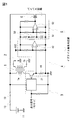
- FIG. 1 is a schematic configuration diagram showing an embodiment of an ignition device for an internal combustion engine according to the present invention.
- the outline of the internal combustion engine ignition device according to the present embodiment is as follows. As shown in FIG. 1, energization / interruption of the primary current flowing in the primary coil 1a of the ignition coil 1 in accordance with an ignition signal from an ECU (engine control unit) The igniter 3 is controlled to control the current flowing from the vehicle battery 11 to the primary coil 1a via the blade fuse 12 and the irreversible safety circuit 13 through the energization control of the igniter 3, and magnetically coupled via the iron core. The induced power of the secondary coil 1 b is controlled to generate an electric spark in the discharge gap of the spark plug 2.
- the internal combustion engine ignition device is, for example, provided with an igniter 3 and the like integrally provided in the casing of the ignition coil 1 and irreversible configured by an irreversible fuse element that blows when a predetermined fusing condition is achieved.
- the safety circuit 13 is also provided integrally with the ignition coil 1 and the igniter 3 and the ignition device for the internal combustion engine is unitized, the convenience as the ignition device for the internal combustion engine becomes high. Of course, you may comprise these as a different body.
- the irreversible safety circuit 13 is set to be equal to or less than the rated current of the blade fuse 12 attached to the vehicle side, so that the irreversible safety circuit 13 is blown before the blade fuse 12 is blown. It is desirable to have the characteristics to be used.
- the igniter 3 includes a power transistor 31, and the current between the collector and the emitter is controlled according to the ignition signal from the engine control unit.
- the power transistor 31 When the power transistor 31 is ON, the primary winding of the ignition coil 1 from the vehicle battery 11 is controlled. Since a current flows from 1a to GND through the power transistor 31 of the igniter 3, it is possible to detect whether or not an overcurrent is flowing through the primary coil 1a by monitoring this current. Therefore, the current detection resistor 41 of the overcurrent detection means 4 is disposed in the current path between the power transistor 31 and the ground, and the current flowing from the primary coil 1a to the igniter 3 is constantly monitored. If the internal circuit of the igniter 3 is short-circuited for some reason, current will intermittently flow from the vehicle battery 11 through the primary coil 1a.
- the period until the prescribed charge is charged in the timer capacitor 51 is the allowable energization time, and the allowable energization time can be arbitrarily set by the constant of the timer capacitor 51.
- the voltage input to Vin + of the allowable energization time determination comparator 52 exceeds the reference voltage Vref2 input to Vin ⁇ , and the output voltage of the allowable energization time determination comparator 52 Is inverted (for example, changed from L level to H level).
- the output signal of the allowable energization time determination comparator 52 can be used as a bypass switching signal.
- the internal combustion engine ignition device is provided with a bypass circuit from the above-described irreversible safety circuit 13 to GND without passing through the ignition coil 1, and in the middle of the bypass circuit, A switching element 6 (for example, a semiconductor element such as a bipolar transistor, an insulated gate bipolar transistor, a MOS-FET, or a thyristor) is provided as switching means for switching between opening and closing of the circuit.
- the switching element 6 is normally open, and is turned on when the bypass switching signal from the allowable energizing time determination comparator 52 is input to close the bypass circuit.
- the switch means for opening and closing the bypass circuit is not limited to a semiconductor element, and a mechanical relay or the like may be used.
- the current flows from the primary winding 1a of the ignition coil 1 through the power transistor 31 of the igniter 3, but the overcurrent detection means 4 and the overcurrent energization time.
- the igniter abnormality determination unit comprising the monitoring means 5
- the switching element 6 is closed by the bypass switching signal,
- the path is switched to a path through which a current flows from the bypass circuit to the GND, a current exceeding the rated current of the irreversible safety circuit 13 is flown, the irreversible safety circuit 13 is blown, and the winding of the ignition coil 1 is caused by an overcurrent exceeding an allowable time.
- the Vin + input of the allowable energization time determination comparator 52 falls below the Vin ⁇ input value, and the output Vout of the allowable energization time determination comparator 52 is inverted (for example, changed from H level to L level), and switching is performed. Since the bypass switching signal is not input to the element 6, the bypass circuit And thus it is disconnected. As described above, if the fusing condition for fusing the irreversible safety circuit 13 (for example, a current exceeding the rated current flows) can be achieved between the time when the bypass circuit is closed and the time when the bypass circuit is opened again. Even if the bypass circuit is opened again, no current flows to the secondary coil 1a of the ignition coil 1.
- the igniter abnormality determination unit has a function of holding the bypass switching signal output until the fusing condition of the irreversible safety circuit 13 is achieved.
- the capacitor discharge occurs between the signal output point to the allowable energization time determination comparator 52 and the signal input point of the overcurrent detection comparator 42 on the upstream side of the timer capacitor 51 in the overcurrent energization time monitoring means 5.
- the discharge characteristic of the time measuring capacitor 51 is adjusted, and the time until the allowable energizing time determining comparator 52 is turned off satisfies the fusing condition of the irreversible safety circuit 13. make sure that it is longer than the necessary and sufficient time. In this case, the irreversible safety circuit 13 can be surely blown before the bypass switching signal is output from the allowable energization time determination comparator 52 and the bypass circuit is opened.
- the igniter abnormality determination unit does not function again.
- the time measuring capacitor 51 and the capacitor discharging time adjusting resistor 53 that can be configured simply and inexpensively are used.
- the bypass switching signal output may be held by a logic circuit or the like.
- the igniter 3, the igniter abnormality determination unit, the switching element 6, the bypass circuit, and the irreversible safety circuit 13 are integrally provided in the main body of the ignition coil 1.
- the present invention is not limited to this, and each may be configured separately or integrated in an appropriate combination.
- the igniter abnormality determination unit or the like is configured to be attached to the outside of the ignition coil 1 as a unit, it can be easily detached without changing the structure of the conventional ignition coil 1. It will be highly convenient.
- the irreversible safety circuit 13, the bypass circuit, and the switching element 6 are provided one for each ignition coil, and only in the ignition coil 1 corresponding to the igniter 3 in which an abnormality is detected, although the irreversible safety circuit 13 is operated, the present invention is not limited to this.
- an irreversible safety circuit, a bypass circuit, and a switch means are provided between a common GND harness that bundles all cylinders of an ignition coil installed for each cylinder of an internal combustion engine and a GND ground, and any one cylinder
- a common GND harness that bundles all cylinders of an ignition coil installed for each cylinder of an internal combustion engine and a GND ground, and any one cylinder
- the energization is cut off in all cylinders bundled with the cylinder, and the energization of the ignition coils of all the cylinders collected by the harness to be connected is performed. May be blocked.
- an irreversible safety circuit, a bypass circuit, and a switch means are provided between the GND harness and the GND ground for each common group in which two or three ignition coils installed for each cylinder of the internal combustion engine are bundled.
Landscapes
- Engineering & Computer Science (AREA)
- Chemical & Material Sciences (AREA)
- Combustion & Propulsion (AREA)
- Mechanical Engineering (AREA)
- General Engineering & Computer Science (AREA)
- Ignition Installations For Internal Combustion Engines (AREA)
Abstract
L'invention porte sur un dispositif d'allumage de haute sécurité pour un moteur à combustion interne, avec lequel une surintensité est rapidement interrompue lorsqu'il se produit une erreur de l'allumeur, en évitant ainsi la production anormale de chaleur due à une surintensité provoquée, par exemple, par un court-circuit entre des enroulements de bobine d'allumage. Lorsqu'une surintensité passe d'une bobine d'allumage (1) à un allumeur (3), un comparateur de détection de surintensité (42) d'un moyen de détection de surintensité (4) se met en position de passage du courant et un condensateur de mesure du temps (51) d'un moyen de surveillance du temps d'excitation de surintensité (5) est excité. Lorsqu'une charge prescrite s'est accumulée, un comparateur (52) servant à déterminer un temps d'excitation admissible s'allume, un signal de commutation de dérivation est émis, le signal de commutation de dérivation émis est maintenu avec une caractéristique de décharge réglée au moyen du condensateur de mesure du temps (51) et d'une résistance de réglage de temps de décharge du condensateur (53), et un élément de commutation (6) est maintenu à l'état fermé, pendant lequel un circuit de dérivation qui fonctionne du circuit de sûreté irréversible (13) à une masse, sans passer à travers la bobine d'allumage (1), reste fermé, un courant excédant le courant nominal circule dans le circuit de sécurité (13), et le circuit de sécurité fond, en évitant ainsi que le courant ne soit transmis d'une batterie de véhicule (11) à la bobine d'allumage (1).
Priority Applications (2)
| Application Number | Priority Date | Filing Date | Title |
|---|---|---|---|
| PCT/JP2012/061158 WO2013157148A1 (fr) | 2012-04-19 | 2012-04-19 | Dispositif d'allumage pour moteur à combustion interne |
| JP2013531985A JP5610453B2 (ja) | 2012-04-19 | 2012-04-19 | 内燃機関用点火装置 |
Applications Claiming Priority (1)
| Application Number | Priority Date | Filing Date | Title |
|---|---|---|---|
| PCT/JP2012/061158 WO2013157148A1 (fr) | 2012-04-19 | 2012-04-19 | Dispositif d'allumage pour moteur à combustion interne |
Publications (1)
| Publication Number | Publication Date |
|---|---|
| WO2013157148A1 true WO2013157148A1 (fr) | 2013-10-24 |
Family
ID=49383127
Family Applications (1)
| Application Number | Title | Priority Date | Filing Date |
|---|---|---|---|
| PCT/JP2012/061158 Ceased WO2013157148A1 (fr) | 2012-04-19 | 2012-04-19 | Dispositif d'allumage pour moteur à combustion interne |
Country Status (2)
| Country | Link |
|---|---|
| JP (1) | JP5610453B2 (fr) |
| WO (1) | WO2013157148A1 (fr) |
Citations (7)
| Publication number | Priority date | Publication date | Assignee | Title |
|---|---|---|---|---|
| JPS60182358A (ja) * | 1984-02-29 | 1985-09-17 | Toshiba Corp | エンジン点火装置の点火制御回路 |
| JPS63205460A (ja) * | 1987-02-23 | 1988-08-24 | Hitachi Ltd | 多気筒内燃機関用電子配電式点火装置 |
| JPS63239367A (ja) * | 1987-03-27 | 1988-10-05 | Hitachi Ltd | 内燃機関用点火装置 |
| JPH0792222A (ja) * | 1993-09-22 | 1995-04-07 | Shindengen Electric Mfg Co Ltd | サイリスタの劣化判定回路及びこれを使用した内燃機関の 点火装置 |
| JPH0797972A (ja) * | 1993-09-28 | 1995-04-11 | Hitachi Ltd | 内燃機関用点火装置、及び点火装置の故障検出装置 |
| JP2004316469A (ja) * | 2003-04-11 | 2004-11-11 | Denso Corp | 内燃機関用点火装置およびそのイグナイタ |
| JP2006070798A (ja) * | 2004-09-02 | 2006-03-16 | Hanshin Electric Co Ltd | 内燃機関用点火コイル装置 |
Family Cites Families (4)
| Publication number | Priority date | Publication date | Assignee | Title |
|---|---|---|---|---|
| JP2916203B2 (ja) * | 1990-04-18 | 1999-07-05 | 森山工業株式会社 | コンデンサー放電式内燃機関用点火装置 |
| JP2002295354A (ja) * | 2001-03-30 | 2002-10-09 | Diamond Electric Mfg Co Ltd | 内燃機関用点火装置 |
| JP4477607B2 (ja) * | 2006-07-25 | 2010-06-09 | 日立オートモティブシステムズ株式会社 | 内燃機関用点火装置 |
| JP4575936B2 (ja) * | 2007-07-09 | 2010-11-04 | 日立オートモティブシステムズ株式会社 | 内燃機関の点火時期制御装置 |
-
2012
- 2012-04-19 WO PCT/JP2012/061158 patent/WO2013157148A1/fr not_active Ceased
- 2012-04-19 JP JP2013531985A patent/JP5610453B2/ja not_active Expired - Fee Related
Patent Citations (7)
| Publication number | Priority date | Publication date | Assignee | Title |
|---|---|---|---|---|
| JPS60182358A (ja) * | 1984-02-29 | 1985-09-17 | Toshiba Corp | エンジン点火装置の点火制御回路 |
| JPS63205460A (ja) * | 1987-02-23 | 1988-08-24 | Hitachi Ltd | 多気筒内燃機関用電子配電式点火装置 |
| JPS63239367A (ja) * | 1987-03-27 | 1988-10-05 | Hitachi Ltd | 内燃機関用点火装置 |
| JPH0792222A (ja) * | 1993-09-22 | 1995-04-07 | Shindengen Electric Mfg Co Ltd | サイリスタの劣化判定回路及びこれを使用した内燃機関の 点火装置 |
| JPH0797972A (ja) * | 1993-09-28 | 1995-04-11 | Hitachi Ltd | 内燃機関用点火装置、及び点火装置の故障検出装置 |
| JP2004316469A (ja) * | 2003-04-11 | 2004-11-11 | Denso Corp | 内燃機関用点火装置およびそのイグナイタ |
| JP2006070798A (ja) * | 2004-09-02 | 2006-03-16 | Hanshin Electric Co Ltd | 内燃機関用点火コイル装置 |
Also Published As
| Publication number | Publication date |
|---|---|
| JPWO2013157148A1 (ja) | 2015-12-21 |
| JP5610453B2 (ja) | 2014-10-22 |
Similar Documents
| Publication | Publication Date | Title |
|---|---|---|
| JP6615457B2 (ja) | 恒久的な無効化を伴う2次電池の保護 | |
| US10714923B2 (en) | Protection device | |
| JP2016524895A (ja) | バッテリモジュール遮断構造 | |
| JP2009138547A (ja) | イグナイタシステム | |
| JP6565244B2 (ja) | イグナイタ用半導体装置、イグナイタシステム及び点火コイルユニット | |
| US20150381170A1 (en) | Semiconductor device | |
| JP2012039861A (ja) | エネルギー供給装置 | |
| RU2440651C2 (ru) | Предохранительное устройство для полупроводникового выключателя | |
| JP2010158108A (ja) | 負荷回路の保護装置 | |
| ITMI20120893A1 (it) | Sistema di accensione elettronica per il motore di un veicolo in caso di guasto | |
| WO2014109067A1 (fr) | Dispositif d'allumage pour moteur à combustion interne | |
| JP7056160B2 (ja) | 内燃機関の点火装置 | |
| JP5610454B2 (ja) | 内燃機関用点火装置 | |
| WO2013161362A1 (fr) | Dispositif de protection pour circuit d'alimentation en électricité | |
| JP5605786B2 (ja) | 内燃機関用点火装置 | |
| JP6296458B2 (ja) | 内燃機関用点火装置 | |
| JP5605785B2 (ja) | 内燃機関用点火装置 | |
| JP5610453B2 (ja) | 内燃機関用点火装置 | |
| JP2017139903A (ja) | 電流遮断装置 | |
| JP2004236405A (ja) | 過電流保護回路 | |
| JP5454635B2 (ja) | イグナイタシステム | |
| JP2020204284A (ja) | 内燃機関用点火システム | |
| JP4477607B2 (ja) | 内燃機関用点火装置 | |
| JP2012217271A (ja) | 電源供給装置および電源供給方法 | |
| JP2021169799A (ja) | 内燃機関の点火装置 |
Legal Events
| Date | Code | Title | Description |
|---|---|---|---|
| ENP | Entry into the national phase |
Ref document number: 2013531985 Country of ref document: JP Kind code of ref document: A |
|
| 121 | Ep: the epo has been informed by wipo that ep was designated in this application |
Ref document number: 12874470 Country of ref document: EP Kind code of ref document: A1 |
|
| NENP | Non-entry into the national phase |
Ref country code: DE |
|
| 122 | Ep: pct application non-entry in european phase |
Ref document number: 12874470 Country of ref document: EP Kind code of ref document: A1 |