WO2013157385A1 - Outil d'adhésion à une rainure pour feuille adhésive - Google Patents
Outil d'adhésion à une rainure pour feuille adhésive Download PDFInfo
- Publication number
- WO2013157385A1 WO2013157385A1 PCT/JP2013/060057 JP2013060057W WO2013157385A1 WO 2013157385 A1 WO2013157385 A1 WO 2013157385A1 JP 2013060057 W JP2013060057 W JP 2013060057W WO 2013157385 A1 WO2013157385 A1 WO 2013157385A1
- Authority
- WO
- WIPO (PCT)
- Prior art keywords
- groove
- rotating body
- ridge
- cut
- cutting blade
- Prior art date
- Legal status (The legal status is an assumption and is not a legal conclusion. Google has not performed a legal analysis and makes no representation as to the accuracy of the status listed.)
- Ceased
Links
Images





Classifications
-
- B—PERFORMING OPERATIONS; TRANSPORTING
- B26—HAND CUTTING TOOLS; CUTTING; SEVERING
- B26B—HAND-HELD CUTTING TOOLS NOT OTHERWISE PROVIDED FOR
- B26B25/00—Hand cutting tools involving disc blades, e.g. motor-driven
- B26B25/005—Manually operated, e.g. pizza cutters
Definitions
- the present invention relates to a pressure-sensitive adhesive sheet sticking tool, and in particular, an adhesive protective sheet covering a groove portion existing on an adherend is cut at the groove portion, and the cut end portion of the groove portion is included in the groove portion. It is intended to be attached to the side.
- a protective sheet with weak adhesion to prevent the painted surface from being damaged or soiled during storage or transportation.
- This protective sheet is affixed on an automobile assembly line, and this affixing operation is composed of three steps of rough affixing, cutting and crimping. Between the front fender and the bonnet, between the fender and door, between the door and door, between the rear fender and trunk panel, etc., it is necessary to open and close it later for maintenance work.
- the protective sheet is cut and folded so that the cut portion is pressed against the inner surface.
- the protective sheet When the protective sheet is cut, if the cutting property (cutting) is poor, the protective sheet is stretched and becomes resistant to wind, and is easily peeled off during storage and transportation. In addition, when the end portion after cutting is not sufficiently crimped to the inside of the groove, the end portion is resistant to wind, and thus easily peels off.
- the series of pasting operations described above are required to be finished properly from the functional aspect of protecting the painted surface and the aesthetic aspect after pasting. Therefore, at present, it is affixed by manpower, man-hours and time. However, there is a demand for efficiency in the operation of attaching the protective sheet, and various studies have been made on the method of applying the protective sheet and the cutting method.
- the treatment in the groove part was considered to cut the adhesive protective sheet that was pasted so as to cover the groove part with a cutter at the groove part. Although a sharp metal blade such as this cutter can cut the protective sheet cleanly, it often causes damage to the coating film on the surface. Moreover, the operation
- disconnection was also required.
- a plastic spatula 42 with a sharp tip 41 as shown in FIG. 14 was used to cut the protective sheet so as to press it toward the back of the groove.
- the treatment with the spatula hardly damages the coating film, but the protective film is not sufficiently cut, the cut ends are stretched and uneven, and the appearance is poor, and the pressure bonding to the groove is insufficient.
- there is a drawback in that a crimping operation for further pasting the cut end portions becomes necessary, and the workability is poor as a whole and takes time and effort.
- the present invention is intended to obtain a sticking tool that can efficiently cut an adhesive protective sheet, which is pasted so as to cover the groove, across the groove as described above. And by this sticking tool, the cut end portion of the protective sheet can be securely stuck to the inner surface of the groove portion to prevent peeling during storage and transportation, and also excellent in workability. .
- a cutting blade and a rotating body are provided on a handle that can be gripped to provide a groove portion pasting tool for an adhesive sheet.
- the rotating body is disk-shaped and has a ridge protruding at the center in the thickness direction so that the adhesive protective sheet covering the grooves on the various adherends extends along the grooves. Can be pushed into.
- the thickness of the rotating body is formed wider than the width of the groove portion, and there is an inclined surface extending from the ridge portion toward both sides of the axis of the rotating body. This inclined surface can affix the cutting edge part of the adhesive protective sheet cut
- the cutting blade can be formed at the leading edge of the ridge of the rotating body or can be provided at a position close to the ridge of the rotating body of the handle.
- the handle may be provided with a guide roller that guides the rotating body with the groove while rotating in contact with the surface of the adherend.
- the groove sticking tool is a part of the adhesive protective sheet that is attached so as to cover the surface of the passenger car. While pressing the body, it moves along the groove while rotating the rotating body.
- the protective sheet positioned in the groove is smoothly cut by the cutting blade of the sticking tool, and the cut end is pressed against the inner surface of the groove by the inclined surface of the rotating body and stuck. Accordingly, the cut end portion of the protective sheet can be reliably attached, and the surface portion of the groove portion can be reliably protected.
- the guide roller it becomes easier to guide and move the rotating body. If the cutting blade is provided separately from the rotating body, the protective sheet can be cut more easily and the surface of the article is not damaged by the cutting blade.
- FIG. 2 is a partially enlarged plan view of what is shown in FIG. 1. It is explanatory drawing which shows the use condition of what is shown in FIG. It is a partially expanded sectional view which shows the cutting state in the groove part of what is shown in FIG. It is a partially expanded plan view which shows the modification of this invention. It is a partially expanded plan view which shows the other modification of this invention. It is a perspective view which shows the other modification of this invention. It is a side view which shows the other example of this invention. It is a partially expanded side view which shows the further another example of this invention. It is a bottom view of what is shown in FIG. It is a partially expanded side view which shows the other example of this invention. It is a bottom view of what is shown in FIG. It is the one part omission perspective view which looked at what was used as a comparative example from the bottom side. It is a perspective view of the spatula used conventionally.
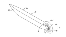
- Rotating body 3 made of a hard material such as plastic, metal or wood is provided at one end of handle 2 that can be held by the hand.
- a material having an appropriate hardness such as MC nylon (trademark), which is a kind of polyamide resin PA-6, can be cited.
- MC nylon trademark
- a substantially U-shaped notch 4 is provided at one end of the handle 1
- a disk-like rotator 3 is fitted to the handle 1 so as to be rotatable by a shaft 5.
- the thickness of the rotating body 3 is larger than the width of the groove portion of the adherend to be described later, and a ridge portion 6 that protrudes outward is formed at the center in the width direction.
- the edge of the ridge 6 is not as sharp as the blade, but is formed into a cutting blade 61 that is sharp enough to be cut by a rotating body 3 that rotates a protective film described later.
- An inclined surface 7 is formed from the ridge 6 at the center of the rotating body 3 toward both sides of the shaft 5. As will be described later, the inclined surface 7 is formed in such a shape that the end portion of the protective sheet of the groove portion cut by the cutting blade 61 of the ridge portion 6 can be pressed against the inner surface of the groove portion. Yes.
- the illustrated inclined surface 7 is formed so as to draw a curved surface that is recessed toward the inside.
- Such a groove sticking tool 1 is used as follows. For example, as shown in FIG. 3, the painted surface of the passenger car 10 is covered with an adhesive protective sheet 11. This adhesive protective sheet 11 is placed across a groove (gap) 14 between a front fender 12 and a hood 13 of a passenger car, between a fender and a door, between a door and a door, and between a rear fender and a trunk panel. Covering.
- the rotating body 3 of the groove portion pasting tool 1 is applied to and pressed against the portion 15 covering the groove portion (gap) 14. Since the protective sheet 11 is cut by the cutting blade 61 of the rotating body 3, it is easy to continuously move the rotating body 3 by pulling it forward along the groove portion 14 while rotating the rotating body 3, or by pushing it in reverse. Can be cut.
- the cut end portion 16 cut by the cutting blade 61 provided at the tip edge of the ridge portion 6 of the rotating body 3 is pushed into the groove portion 14 by the inclined surface 7 of the rotating body 3 as shown in FIG. It is done. And since the cut end portion 16 is pressed against the inner surface 17 of the groove portion by the inclined surface 7 and is stuck, it can be reliably attached without wrinkles along the groove portion. As a result, the surface of the groove can be reliably protected.
- the ridge portion 6 of the rotating body 3 can be provided so as to be biased to one side in the thickness direction as shown in FIG. In such a case, it is convenient to use it in a place where it is better to change the cutting width in the groove.
- a gap 20 may be provided at the center of the ridge 6 to form double ridges 21 and 21. In this case, it is also possible to divide the rotator 3 and form the spacer 22 therebetween.
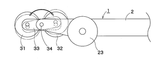
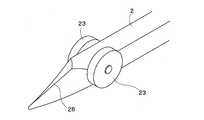
- the handle 2 can be provided with guide rollers 23 on both sides for guiding the rotating body 3 in the groove portion.
- the guide roller 23 is positioned so as to straddle the groove portion 14 and can be moved by pulling or pushing while rotating while being in contact with the surface of the adherend. With this guide roller 23, the sticking tool 1 can be stably moved along the groove portion while rotating the rotating body 3. As a result, the efficiency of the affixing operation can be improved, and the protective sheet can be cut more securely and the end affixing process can be performed.
- the above rotating body can be configured such that two rotating bodies 31 and 32 are connected in the front-rear direction by a connecting rod 33 and can be swung by a shaft 34.
- the protective sheet can be cut with one rotating body, and the cut end can be more reliably attached to the inner surface of the groove with the other rotating body, so that it can be used conveniently.
- a guide roller 23 is also provided.
- the handle 2 can be provided with a cutting blade 24 for cutting an adhesive protective sheet covering the groove at a position close to the ridge 6 of the rotating body 3 as shown in FIGS.
- the cutting blade 24 may be as sharp as a cutter blade, or may not be as sharp as spring steel. If the handle is pulled forward, the cutting blade 24 can smoothly cut the protective sheet even when the protective sheet is thick or slightly strong. And after the said cutting
- Such a cutting blade 24 is provided at a position close to the ridge 6 of the rotating body 3.
- the cutting blade 24 does not directly touch the surface of an adherend such as an automobile, except when the protective sheet is cut with the rotating body 3 inserted into the groove 14. Therefore, the cutting blade 24 does not inadvertently damage the surface of the adherend. Further, when the cutting blade 24 is provided, it is not required until the rotary body 3 is cut with the protective sheet in the groove portion. Therefore, the rotating body 3 can also be formed of relatively soft plastic or rubber.
- a gap 20 can be provided in the center of the ridge 6 described above to form double ridges 21 and 21.
- the cutting edge of the cutting blade is positioned in the gap 20 between the double ridges 21, 21, or on the same plane outside the gap 20.
- the spatula part 25 can be formed in the edge part on the opposite side to the rotary body 3 of the handle
- FIG. The spatula portion 25 can be conveniently used when correcting the pasting state in the groove portion, processing or correcting a portion such as a corner, and the like.
- Example 1 The groove part pasting tool shown in FIGS.
- Example 2 A groove pasting tool provided with a guide roller shown in FIG.
- Example 3 The groove part pasting tool shown in FIGS.
- Example 4 The groove sticking tool shown in FIGS.
- Comparative Example 1 Conventional spatula shown in FIG. Comparative Example 2: A cutting blade is formed at the tip of the handle shown in FIG. 13 and a guide roller is provided.
- Test specimen A protective sheet in which a rubber-based adhesive layer having a thickness of 10 ⁇ m was provided on a polypropylene substrate having a thickness of 40 ⁇ m and a sheet coated on a surface having a groove interval of 5 mm and a groove depth of 10 mm was prepared. .
- Example 1 the sheet cutting workability and the appearance of the construction part are almost good, and the pressure bonding property to the groove part is good, and a good result is obtained as compared with the comparative example.
- Example 2 both the sheet cutting workability and the pressure-bonding property to the groove portion are better than those in Example 1, and better results are obtained than in the comparative example.
- the sheet cutting workability, the pressure bonding property to the groove, and the appearance of the construction part are further improved as compared to Examples 1 and 2, and excellent results are obtained. I understand.
Landscapes
- Life Sciences & Earth Sciences (AREA)
- Forests & Forestry (AREA)
- Engineering & Computer Science (AREA)
- Mechanical Engineering (AREA)
- Knives (AREA)
- Adhesive Tapes (AREA)
Abstract
L'invention concerne une feuille protectrice adhésive qui recouvre une rainure présente dans une partie adhérée, et qui est coupée le long de la rainure, et l'extrémité coupée est collée à une surface côté intérieur de la rainure pour une finition propre. Une lame de coupe et un corps rotatif (3) sont situés dans une poignée facile à prendre en main (2) pour constituer un outil d'adhésion de rainure (1). Le corps rotatif (3) est en forme de disque, une arête (6) dépasse dans la partie centrale dans la direction de l'épaisseur, et le bord extrémité avant constitue la lame de coupe. Le corps rotatif (3) peut couper, le long de rainures présentes sur différentes parties adhérées, des feuilles protectrices adhésives qui passent au-dessus des rainures. L'épaisseur du corps rotatif (3) est conçue pour être plus large que la largeur de la rainure, et une surface inclinée (7) est présente de façon à s'étendre des deux côtés d'un arbre (5) du corps rotatif (3) à partir de l'arête (6). La surface inclinée (7) peut faire coller l'extrémité coupée de la feuille protectrice adhésive coupée par une lame de coupe (61) de l'arête (6) à la surface côté intérieur tout en poussant l'extrémité coupée dans la rainure.
Applications Claiming Priority (2)
| Application Number | Priority Date | Filing Date | Title |
|---|---|---|---|
| JP2012096858A JP2013223587A (ja) | 2012-04-20 | 2012-04-20 | 粘着シートの溝部貼付用具 |
| JP2012-096858 | 2012-04-20 |
Publications (1)
| Publication Number | Publication Date |
|---|---|
| WO2013157385A1 true WO2013157385A1 (fr) | 2013-10-24 |
Family
ID=49383350
Family Applications (1)
| Application Number | Title | Priority Date | Filing Date |
|---|---|---|---|
| PCT/JP2013/060057 Ceased WO2013157385A1 (fr) | 2012-04-20 | 2013-04-02 | Outil d'adhésion à une rainure pour feuille adhésive |
Country Status (2)
| Country | Link |
|---|---|
| JP (1) | JP2013223587A (fr) |
| WO (1) | WO2013157385A1 (fr) |
Cited By (2)
| Publication number | Priority date | Publication date | Assignee | Title |
|---|---|---|---|---|
| DE102018216534A1 (de) * | 2018-09-27 | 2020-04-02 | Bayerische Motoren Werke Aktiengesellschaft | Schneidvorrichtung sowie Verfahren zum Schneiden einer Maskierung eines Kraftfahrzeugbauteils |
| JP7553895B1 (ja) | 2024-03-22 | 2024-09-19 | 株式会社Value Springs技術士事務所 | ピザカッター |
Families Citing this family (1)
| Publication number | Priority date | Publication date | Assignee | Title |
|---|---|---|---|---|
| JP7809241B1 (ja) * | 2025-08-05 | 2026-01-30 | 有井 恒男 | フィルムカッター |
Citations (4)
| Publication number | Priority date | Publication date | Assignee | Title |
|---|---|---|---|---|
| US5569285A (en) * | 1994-11-02 | 1996-10-29 | Webb; Nicholas J. | Scalpel with rotary depth guard |
| JP2008087120A (ja) * | 2006-10-03 | 2008-04-17 | Yokohama Rubber Co Ltd:The | シート状部材の切断装置 |
| JP2009542310A (ja) * | 2006-06-30 | 2009-12-03 | エスセーアー・ハイジーン・プロダクツ・アーベー | 吸収性製品の製造装置 |
| US20110225831A1 (en) * | 2010-03-17 | 2011-09-22 | Greenwood William T | Rotary Knife For Drywall and the Like |
-
2012
- 2012-04-20 JP JP2012096858A patent/JP2013223587A/ja active Pending
-
2013
- 2013-04-02 WO PCT/JP2013/060057 patent/WO2013157385A1/fr not_active Ceased
Patent Citations (4)
| Publication number | Priority date | Publication date | Assignee | Title |
|---|---|---|---|---|
| US5569285A (en) * | 1994-11-02 | 1996-10-29 | Webb; Nicholas J. | Scalpel with rotary depth guard |
| JP2009542310A (ja) * | 2006-06-30 | 2009-12-03 | エスセーアー・ハイジーン・プロダクツ・アーベー | 吸収性製品の製造装置 |
| JP2008087120A (ja) * | 2006-10-03 | 2008-04-17 | Yokohama Rubber Co Ltd:The | シート状部材の切断装置 |
| US20110225831A1 (en) * | 2010-03-17 | 2011-09-22 | Greenwood William T | Rotary Knife For Drywall and the Like |
Cited By (4)
| Publication number | Priority date | Publication date | Assignee | Title |
|---|---|---|---|---|
| DE102018216534A1 (de) * | 2018-09-27 | 2020-04-02 | Bayerische Motoren Werke Aktiengesellschaft | Schneidvorrichtung sowie Verfahren zum Schneiden einer Maskierung eines Kraftfahrzeugbauteils |
| JP7553895B1 (ja) | 2024-03-22 | 2024-09-19 | 株式会社Value Springs技術士事務所 | ピザカッター |
| WO2025197806A1 (fr) * | 2024-03-22 | 2025-09-25 | 株式会社Value Springs技術士事務所 | Dispositif de coupe de pizza |
| JP2025146540A (ja) * | 2024-03-22 | 2025-10-03 | 株式会社Value Springs技術士事務所 | ピザカッター |
Also Published As
| Publication number | Publication date |
|---|---|
| JP2013223587A (ja) | 2013-10-31 |
Similar Documents
| Publication | Publication Date | Title |
|---|---|---|
| CN103282213B (zh) | 装饰性制品 | |
| WO2013157385A1 (fr) | Outil d'adhésion à une rainure pour feuille adhésive | |
| US4473419A (en) | Method of forming and bonding a panel repair patch | |
| US20120070604A1 (en) | Methods for preparing modified release liners and modified adhesive articles | |
| JP5475726B2 (ja) | シート貼付方法およびシート貼付治具 | |
| EP2714287B1 (fr) | Dispositif de masquage durant le traitement d'une surface | |
| WO2019009318A1 (fr) | Outil de fixation de surface de paroi | |
| CN102712330A (zh) | 用于给车辆室内部件镶皮的方法 | |
| US8215364B2 (en) | Ergonomic squeegee with blade for adhesions and detachment | |
| AU2012100158A4 (en) | Hand Applicator for Adhesive Sheet | |
| US10384362B2 (en) | Tape system with a longitudinal filament for slitting film | |
| JP2009040039A (ja) | 装飾用シート、成形品および輸送機器 | |
| JP4448540B2 (ja) | 成形品の製造方法および自動車両 | |
| JP4074945B2 (ja) | ぼかし粘着テープ、その粘着テープを用いた塗装方法、その粘着テープの成形装置 | |
| EP3287195A1 (fr) | Kit de masquage à positionnement optimisé et procédé associé | |
| JP6163618B1 (ja) | 自己粘着フィルム及びその製造方法 | |
| CN224177050U (zh) | 一种便于分离的不干胶标签 | |
| JP4693711B2 (ja) | マスキング材 | |
| US12084606B2 (en) | Tape assembly and method of using the same | |
| JPH07328528A (ja) | 車体上塗り塗膜の保護方法 | |
| JP2012136591A (ja) | 剥がし用テープ及びその貼付方法 | |
| FR3106343A1 (fr) | Etiquette avec languette de préhension | |
| JP2008229452A (ja) | 塗膜保護用粘着フィルムの貼付方法 | |
| JP2010247263A (ja) | ピンセット | |
| WO2020155129A1 (fr) | Distributeur de ruban adhésif |
Legal Events
| Date | Code | Title | Description |
|---|---|---|---|
| 121 | Ep: the epo has been informed by wipo that ep was designated in this application |
Ref document number: 13778394 Country of ref document: EP Kind code of ref document: A1 |
|
| NENP | Non-entry into the national phase |
Ref country code: DE |
|
| 122 | Ep: pct application non-entry in european phase |
Ref document number: 13778394 Country of ref document: EP Kind code of ref document: A1 |