WO2013157471A1 - Dispositif d'embrayage - Google Patents
Dispositif d'embrayage Download PDFInfo
- Publication number
- WO2013157471A1 WO2013157471A1 PCT/JP2013/060910 JP2013060910W WO2013157471A1 WO 2013157471 A1 WO2013157471 A1 WO 2013157471A1 JP 2013060910 W JP2013060910 W JP 2013060910W WO 2013157471 A1 WO2013157471 A1 WO 2013157471A1
- Authority
- WO
- WIPO (PCT)
- Prior art keywords
- spring
- lock spring
- lock
- adjustment
- drum
- Prior art date
- Legal status (The legal status is an assumption and is not a legal conclusion. Google has not performed a legal analysis and makes no representation as to the accuracy of the status listed.)
- Ceased
Links
Images



Classifications
-
- F—MECHANICAL ENGINEERING; LIGHTING; HEATING; WEAPONS; BLASTING
- F16—ENGINEERING ELEMENTS AND UNITS; GENERAL MEASURES FOR PRODUCING AND MAINTAINING EFFECTIVE FUNCTIONING OF MACHINES OR INSTALLATIONS; THERMAL INSULATION IN GENERAL
- F16D—COUPLINGS FOR TRANSMITTING ROTATION; CLUTCHES; BRAKES
- F16D13/00—Friction clutches
- F16D13/08—Friction clutches with a helical band or equivalent member, which may be built up from linked parts, with more than one turn embracing a drum or the like, with or without an additional clutch actuating the end of the band
-
- B—PERFORMING OPERATIONS; TRANSPORTING
- B60—VEHICLES IN GENERAL
- B60N—SEATS SPECIALLY ADAPTED FOR VEHICLES; VEHICLE PASSENGER ACCOMMODATION NOT OTHERWISE PROVIDED FOR
- B60N2/00—Seats specially adapted for vehicles; Arrangement or mounting of seats in vehicles
- B60N2/02—Seats specially adapted for vehicles; Arrangement or mounting of seats in vehicles the seat or part thereof being movable, e.g. adjustable
- B60N2/04—Seats specially adapted for vehicles; Arrangement or mounting of seats in vehicles the seat or part thereof being movable, e.g. adjustable the whole seat being movable
- B60N2/16—Seats specially adapted for vehicles; Arrangement or mounting of seats in vehicles the seat or part thereof being movable, e.g. adjustable the whole seat being movable height-adjustable
- B60N2/1635—Seats specially adapted for vehicles; Arrangement or mounting of seats in vehicles the seat or part thereof being movable, e.g. adjustable the whole seat being movable height-adjustable characterised by the drive mechanism
- B60N2/167—Ratchet mechanism
-
- A—HUMAN NECESSITIES
- A47—FURNITURE; DOMESTIC ARTICLES OR APPLIANCES; COFFEE MILLS; SPICE MILLS; SUCTION CLEANERS IN GENERAL
- A47C—CHAIRS; SOFAS; BEDS
- A47C7/00—Parts, details, or accessories of chairs or stools
- A47C7/50—Supports for the feet or the legs
-
- B—PERFORMING OPERATIONS; TRANSPORTING
- B60—VEHICLES IN GENERAL
- B60N—SEATS SPECIALLY ADAPTED FOR VEHICLES; VEHICLE PASSENGER ACCOMMODATION NOT OTHERWISE PROVIDED FOR
- B60N2/00—Seats specially adapted for vehicles; Arrangement or mounting of seats in vehicles
- B60N2/02—Seats specially adapted for vehicles; Arrangement or mounting of seats in vehicles the seat or part thereof being movable, e.g. adjustable
- B60N2/04—Seats specially adapted for vehicles; Arrangement or mounting of seats in vehicles the seat or part thereof being movable, e.g. adjustable the whole seat being movable
- B60N2/16—Seats specially adapted for vehicles; Arrangement or mounting of seats in vehicles the seat or part thereof being movable, e.g. adjustable the whole seat being movable height-adjustable
- B60N2/1635—Seats specially adapted for vehicles; Arrangement or mounting of seats in vehicles the seat or part thereof being movable, e.g. adjustable the whole seat being movable height-adjustable characterised by the drive mechanism
- B60N2/165—Gear wheel driven mechanism
-
- B—PERFORMING OPERATIONS; TRANSPORTING
- B60—VEHICLES IN GENERAL
- B60N—SEATS SPECIALLY ADAPTED FOR VEHICLES; VEHICLE PASSENGER ACCOMMODATION NOT OTHERWISE PROVIDED FOR
- B60N2/00—Seats specially adapted for vehicles; Arrangement or mounting of seats in vehicles
- B60N2/02—Seats specially adapted for vehicles; Arrangement or mounting of seats in vehicles the seat or part thereof being movable, e.g. adjustable
- B60N2/04—Seats specially adapted for vehicles; Arrangement or mounting of seats in vehicles the seat or part thereof being movable, e.g. adjustable the whole seat being movable
- B60N2/16—Seats specially adapted for vehicles; Arrangement or mounting of seats in vehicles the seat or part thereof being movable, e.g. adjustable the whole seat being movable height-adjustable
- B60N2/168—Seats specially adapted for vehicles; Arrangement or mounting of seats in vehicles the seat or part thereof being movable, e.g. adjustable the whole seat being movable height-adjustable and provided with braking systems
-
- B—PERFORMING OPERATIONS; TRANSPORTING
- B60—VEHICLES IN GENERAL
- B60N—SEATS SPECIALLY ADAPTED FOR VEHICLES; VEHICLE PASSENGER ACCOMMODATION NOT OTHERWISE PROVIDED FOR
- B60N2/00—Seats specially adapted for vehicles; Arrangement or mounting of seats in vehicles
- B60N2/02—Seats specially adapted for vehicles; Arrangement or mounting of seats in vehicles the seat or part thereof being movable, e.g. adjustable
- B60N2/22—Seats specially adapted for vehicles; Arrangement or mounting of seats in vehicles the seat or part thereof being movable, e.g. adjustable the back-rest being adjustable
- B60N2/2213—Gear wheel driven mechanism
-
- B—PERFORMING OPERATIONS; TRANSPORTING
- B60—VEHICLES IN GENERAL
- B60N—SEATS SPECIALLY ADAPTED FOR VEHICLES; VEHICLE PASSENGER ACCOMMODATION NOT OTHERWISE PROVIDED FOR
- B60N2/00—Seats specially adapted for vehicles; Arrangement or mounting of seats in vehicles
- B60N2/02—Seats specially adapted for vehicles; Arrangement or mounting of seats in vehicles the seat or part thereof being movable, e.g. adjustable
- B60N2/22—Seats specially adapted for vehicles; Arrangement or mounting of seats in vehicles the seat or part thereof being movable, e.g. adjustable the back-rest being adjustable
- B60N2/2227—Seats specially adapted for vehicles; Arrangement or mounting of seats in vehicles the seat or part thereof being movable, e.g. adjustable the back-rest being adjustable and provided with braking systems
-
- B—PERFORMING OPERATIONS; TRANSPORTING
- B60—VEHICLES IN GENERAL
- B60N—SEATS SPECIALLY ADAPTED FOR VEHICLES; VEHICLE PASSENGER ACCOMMODATION NOT OTHERWISE PROVIDED FOR
- B60N2/00—Seats specially adapted for vehicles; Arrangement or mounting of seats in vehicles
- B60N2/02—Seats specially adapted for vehicles; Arrangement or mounting of seats in vehicles the seat or part thereof being movable, e.g. adjustable
- B60N2/22—Seats specially adapted for vehicles; Arrangement or mounting of seats in vehicles the seat or part thereof being movable, e.g. adjustable the back-rest being adjustable
- B60N2/224—Stepwise movement mechanisms, e.g. ratchets
-
- B—PERFORMING OPERATIONS; TRANSPORTING
- B60—VEHICLES IN GENERAL
- B60N—SEATS SPECIALLY ADAPTED FOR VEHICLES; VEHICLE PASSENGER ACCOMMODATION NOT OTHERWISE PROVIDED FOR
- B60N2/00—Seats specially adapted for vehicles; Arrangement or mounting of seats in vehicles
- B60N2/62—Thigh-rests
-
- B—PERFORMING OPERATIONS; TRANSPORTING
- B60—VEHICLES IN GENERAL
- B60N—SEATS SPECIALLY ADAPTED FOR VEHICLES; VEHICLE PASSENGER ACCOMMODATION NOT OTHERWISE PROVIDED FOR
- B60N2/00—Seats specially adapted for vehicles; Arrangement or mounting of seats in vehicles
- B60N2/90—Details or parts not otherwise provided for
- B60N2/919—Positioning and locking mechanisms
- B60N2/933—Positioning and locking mechanisms rotatable
- B60N2/938—Positioning and locking mechanisms rotatable and provided with braking systems
-
- B—PERFORMING OPERATIONS; TRANSPORTING
- B60—VEHICLES IN GENERAL
- B60N—SEATS SPECIALLY ADAPTED FOR VEHICLES; VEHICLE PASSENGER ACCOMMODATION NOT OTHERWISE PROVIDED FOR
- B60N2/00—Seats specially adapted for vehicles; Arrangement or mounting of seats in vehicles
- B60N2/90—Details or parts not otherwise provided for
- B60N2/919—Positioning and locking mechanisms
- B60N2/933—Positioning and locking mechanisms rotatable
- B60N2/943—Stepwise movement mechanisms, e.g. ratchets
-
- F—MECHANICAL ENGINEERING; LIGHTING; HEATING; WEAPONS; BLASTING
- F16—ENGINEERING ELEMENTS AND UNITS; GENERAL MEASURES FOR PRODUCING AND MAINTAINING EFFECTIVE FUNCTIONING OF MACHINES OR INSTALLATIONS; THERMAL INSULATION IN GENERAL
- F16D—COUPLINGS FOR TRANSMITTING ROTATION; CLUTCHES; BRAKES
- F16D41/00—Freewheels or freewheel clutches
- F16D41/20—Freewheels or freewheel clutches with expandable or contractable clamping ring or band
- F16D41/206—Freewheels or freewheel clutches with expandable or contractable clamping ring or band having axially adjacent coils, e.g. helical wrap-springs
-
- F—MECHANICAL ENGINEERING; LIGHTING; HEATING; WEAPONS; BLASTING
- F16—ENGINEERING ELEMENTS AND UNITS; GENERAL MEASURES FOR PRODUCING AND MAINTAINING EFFECTIVE FUNCTIONING OF MACHINES OR INSTALLATIONS; THERMAL INSULATION IN GENERAL
- F16D—COUPLINGS FOR TRANSMITTING ROTATION; CLUTCHES; BRAKES
- F16D49/00—Brakes with a braking member co-operating with the periphery of a drum, wheel-rim, or the like
- F16D49/02—Brakes with a braking member co-operating with the periphery of a drum, wheel-rim, or the like shaped as a helical band or coil with more than one turn, with or without intensification of the braking force by the tension of the band or contracting member
- F16D49/04—Brakes with a braking member co-operating with the periphery of a drum, wheel-rim, or the like shaped as a helical band or coil with more than one turn, with or without intensification of the braking force by the tension of the band or contracting member mechanically actuated
-
- F—MECHANICAL ENGINEERING; LIGHTING; HEATING; WEAPONS; BLASTING
- F16—ENGINEERING ELEMENTS AND UNITS; GENERAL MEASURES FOR PRODUCING AND MAINTAINING EFFECTIVE FUNCTIONING OF MACHINES OR INSTALLATIONS; THERMAL INSULATION IN GENERAL
- F16D—COUPLINGS FOR TRANSMITTING ROTATION; CLUTCHES; BRAKES
- F16D63/00—Brakes not otherwise provided for; Brakes combining more than one of the types of groups F16D49/00 - F16D61/00
Definitions
- the present invention relates to a clutch device that is interposed between a first member and a second member and switches between an unlocked state in which the second member can be rotated relative to the first member and a locked state in which the second member cannot be rotated.
- a lock spring having an outer diameter slightly larger than the inner diameter of the lock drum is internally fitted in the lock drum.
- the operation lever for example, reference numeral 90 in FIG. 7 of Patent Document 2
- the outer peripheral surface of the lock spring reference numeral 32 in the same figure
- the lock drum reference numeral 20 in the same figure
- the present invention solves the above-described problem, and is a lock that can rotate a second member (such as an output shaft for raising and lowering a vehicle seat) relative to a first member (such as a member that fixes a lock drum).
- a clutch device that switches between a released state and a non-rotatable locked state, and is a highly safe clutch device that can reliably maintain the locked state even when an excessive load is applied to the second member side Is to provide. It is also an object of the present invention to provide such a highly safe clutch device with a structure as simple as possible.
- a clutch device that is interposed between the first member and the second member, and switches between an unlocked state in which the second member can be rotated with respect to the first member and a locked state in which the second member cannot be rotated,
- a lock drum fixed to the first member side;
- An output shaft plate fixed to the second member side;
- a lock spring step portion formed of a lock spring bent portion bent toward the center side of the lock spring and a lock spring bottom portion bent from the lock spring bent portion in the winding forward direction of the lock spring is formed on the lock spring,
- a lock spring tension side contact is provided on the side where the diameter of the lock spring is reduced.
- a lock spring pressing side contact is provided on the side of the lock spring bent portion where the diameter of the lock spring is expanded,
- the adjustment drum is provided with a lock spring operation piece for pressing the lock spring tension side contact,
- the lock spring pressing piece is pressed against the lock spring pressing side contact of the lock spring bent portion in the lock spring step portion, so that an excessive load is applied to the second member side, and the load is increased.
- the lock spring pressing piece is guided to the inside of the lock spring (the gap between the inner surface of the lock spring and the outer surface of the lock spring step) by the lock spring bottom, and is locked.
- the lock spring bottom is locked.
- the bottom portion of the lock spring may be in a free state, but is preferably as follows. That is, it is preferable to further include a lock spring bottom receiving drum that is fitted in the lock spring and receives the lock spring bottom at the outer peripheral surface thereof. Thereby, even when an excessive load is applied to the second member side, it is possible to prevent the lock spring bottom portion from rising and to maintain the position relative to the lock spring pressing piece. Therefore, the lock spring pressing piece guided in the gap between the inner peripheral surface of the lock drum and the outer peripheral surface of the lock spring intentionally expresses a state in which the lock spring pressing piece is crushed and meshed in the gap, and the locked state can be maintained more reliably. It becomes possible.
- the place where the lock spring step is provided is not particularly limited, and may be either the end or the middle of the lock spring. You may form a lock spring step part in the intermediate part (For example, the 4th volume in case a lock spring is 7 volumes) of a lock spring. Even if the lock spring step portion is provided at any of these locations, the above-described effects can be obtained.
- the adjustment spring is formed with an adjustment spring step portion formed of an adjustment spring bent portion bent toward the center side of the adjustment spring, and an adjustment spring bottom portion bent from the adjustment spring bent portion in the winding forward direction of the adjustment spring.
- An adjustment spring tension side contact is provided on the adjustment spring curved portion on the side where the diameter of the adjustment spring is reduced
- An adjustment spring pressing side contact is provided on the side of the adjustment spring curved portion where the adjustment spring is expanded
- the return drum is provided with an adjustment spring operation piece for pressing the adjustment spring tension side contact
- the operation drum is provided with an adjustment spring pressing piece for pressing the adjustment spring pressing side contact
- This configuration is suitable for use in a vehicle seat height adjustment device or the like.
- the reason why the adjustment spring step portion including the adjustment spring curved portion and the adjustment spring bottom portion is formed on the adjustment spring is the same as that of the lock spring. It is the same as that of the lock spring that the adjustment spring step portion may be provided at either the end portion or the midway portion (including the intermediate portion) of the adjustment spring. Further, the adjustment spring bottom receiving drum that is fitted in the adjustment spring and receives the adjustment spring bottom at the outer peripheral surface thereof is preferably the same as the lock spring.
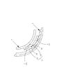
- This recess increases the frictional force of the lock spring against the inner peripheral surface of the lock drum and the frictional force of the adjustment spring against the inner peripheral surface of the adjustment drum, thereby increasing the locking force. Since this recess is a small one having a width of 0.2 to 0.5 mm and a depth of 0.05 to 0.2 mm, it is preferable to perform plastic working using a mold or a rolling die. From these, the strength of the lock spring and the strength of the adjusting spring are not affected. (Fig. 4)
- the clutch device of the present invention when used in a ottoman device for a link mechanism in which the first member and the second member are part of the constituent members of the link mechanism and the adjustment drum is a clutch operation member, the locking force is A high and safe ottoman device can be provided.
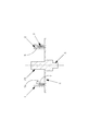
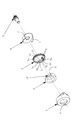
- FIG. 2 is a cross-sectional view showing a state where the clutch device of the first embodiment is cut along the AA plane in FIG. 1. It is the perspective view which showed the state which decomposed
- FIG. 5 is a cross-sectional view showing an example of a state after an excessive load is applied to the second member side from the state shown in FIG. 4 in the clutch device of the second embodiment.
- FIG. 9 is a cross-sectional view showing a state in which the clutch device of the fourth embodiment is cut along the BB plane in FIG. 8. It is sectional drawing which showed the state which cut
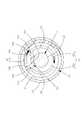
- FIG. 1 is a cross-sectional view showing a state in which the clutch device of the first embodiment is cut along a plane perpendicular to the output shaft 5.
- FIG. 2 is a cross-sectional view showing a state in which the clutch device of the first embodiment is cut along the AA plane in FIG.
- the clutch device according to the first embodiment is interposed between the first member and the second member, and switches between an unlocked state in which the second member can be rotated with respect to the first member and a locked state in which the second member cannot be rotated. It has become.
- the clutch device of the first embodiment includes a lock drum 1, an output shaft plate 6, an output shaft 5, a lock spring 3, and an adjustment drum 2.
- the lock drum 1 is fixed to a first member (not shown), and the output shaft plate 6 is fixed to a second member (not shown) via an output shaft 5 fixed thereto.
- the lock spring 3 has an outer diameter that is several percent larger than the inner diameter of the lock drum 1 in a free state, and is forcibly fitted into the lock drum 1.
- the first member and the second member differ depending on the use of the clutch device, for example, when the clutch device is incorporated in an elevating mechanism (lifter device) that adjusts the height of the vehicle seat, the first member is:
- the frame is a seat bottom in a vehicle seat
- the second member is an input side member of the lifting mechanism.
- the lock spring 3 includes a lock spring stage 3d bent to the center thereof, and a lock spring stage 3d bent from the lock spring bent part 3d in the winding forward direction of the lock spring 3. Part 3c is formed.
- the lock spring step portion 3 c is provided at both ends of the lock spring 3.
- the side of the lock spring bent portion 3d on which the diameter of the lock spring 3 is reduced is a lock spring tension side contact 3a
- the side of the lock spring bent portion 3d on which the diameter of the lock spring 3 is increased is a lock spring pressing side contact 3b.
- the adjustment drum 2 is provided with a lock spring operating piece 8 for pressing the lock spring tension side contact 3a.
- the output shaft plate 6 is provided with a lock spring pressing piece 7 for pressing the lock spring pressing side contact 3b.
- the lock spring operating piece 8 provided integrally therewith is locked to the lock spring.
- the lock spring 3d is pressed by the side contact 3a to reduce the diameter of the lock spring 3, so that the lock spring 3 is rotatable with respect to the lock drum 1 (lock spring movable state). That is, an unlocked state in which the second member (the member with the output shaft 5 fixed) can be rotated with respect to the first member (the member with the lock drum 1 fixed) is developed.
- the lock spring 3 expands to its original state and comes into close contact with the inner peripheral surface of the lock drum 1 so that it cannot rotate with respect to the lock drum 1 (lock spring fixed state). . That is, a locked state in which the second member cannot be rotated with respect to the first member appears.
- the lock spring pressing piece 7 presses the lock spring 3 with the lock spring pressing side contact 3b. Since the lock spring 3 is further in close contact with the inner peripheral surface of the lock drum 1, a large locking force can be obtained.
- the lock spring pressing piece 7 is moved to the inside of the lock spring 3 (the inner peripheral surface of the lock spring 3 and the outer peripheral surface of the lock spring step portion 3c by the lock spring bottom 3e. It can be guided to the gap) to keep the locked state firmly.
- FIG. 3 is a perspective view showing a state in which the clutch device of the second embodiment is disassembled into parts.
- FIG. 4 is a cross-sectional view showing a state where the periphery of the lock spring pressing piece 7 in the clutch device of the second embodiment is cut by a plane perpendicular to the output shaft 5.
- FIG. 5 is a cross-sectional view showing an example of a state after an excessive load is applied to the second member side from the state shown in FIG. 4 in the clutch device of the second embodiment.
- the clutch device of the second embodiment is provided with a lock spring bottom receiving drum 17 fitted in the lock spring 3 as shown in FIGS.
- the lock spring bottom receiving drum 17 is in the relationship between the inner side and the outer side of the same member with respect to the adjustment drum 2.
- the lock spring bottom receiving drum 17 receives the lock spring bottom 3e on its outer peripheral surface so that the lock spring bottom 3e is not deformed even when a large load is applied from the lock spring pressing piece 7 to the lock spring bent portion 3d.
- the shape of the lock spring step portion 3c is maintained, and the lock spring pressing piece 7 is reliably guided by the gap between the inner peripheral surface of the lock spring 3 and the outer peripheral surface of the lock spring step portion 3c.
- the lock spring pressing piece 7 guided to the gap is in a state of being crushed and meshed in the gap as shown in FIG. Note that this state of deformation is an example for explanation, and actually a form that is crushed and bitten in a different form is selected.
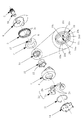
- FIG. 6 is a perspective view showing a state in which the clutch device of the third embodiment is disassembled into parts.
- FIG. 7 is a cross-sectional view showing a state in which the intermittent feed mechanism in the clutch device of the third embodiment is cut along a plane perpendicular to the output shaft 5.
- the clutch device according to the second embodiment described above is a lock mechanism including a lock drum 1, an adjustment drum 2, a lock spring 3, an output shaft 5, and an output shaft plate 6.
- the clutch device of the third embodiment has an adjustment spring 10, an operation drum 11, a return drum 12, a return spring 13, and an adjustment spring bottom in addition to the lock mechanism.
- An intermittent feeding mechanism constituted by the receiving drum 18 is provided.
- An operation plate 14 is provided on the outer side of the return spring 13. The operation plate 14 is fixed to operation means such as an operation lever (not shown).
- the adjustment spring 10 has an outer diameter that is several percent larger than the inner diameter of the adjustment drum 2 in a free state, and is forcibly fitted into the adjustment drum 1 as shown in FIG.
- the operation drum 11 is disposed inside the adjustment spring 10, and one end thereof is integrally fixed to the operation plate 14.
- the return drum 12 has a small-diameter portion on one end side fitted into the adjustment spring 10 through an opening provided in the lock drum 1, and a large-diameter portion on the other end side is disposed outside the lock drum 1.
- the return drum 12 is divided into a first return drum 12a and a second return drum 12b.
- the return spring 13 is held by the enlarged diameter portion of the return drum 12.
- a return spring contact piece 4 provided on the lock drum 1 is disposed in a gap between a pair of bent portions provided at both ends of the return spring 13.
- the return spring 13 is for returning the return drum 12 displaced from the initial position to the initial position.
- the adjustment spring bottom receiving drum 18 is integrally provided coaxially with the output shaft 5.
- the adjustment spring 10 includes an adjustment spring bent portion 10d bent toward the center thereof, and an adjustment spring bottom portion bent in the winding forward direction of the adjustment spring 10 from the adjustment spring bent portion 10d.
- An adjustment spring step portion 10c is formed.
- the adjustment spring step portions 3c are provided at both ends of the adjustment spring 10.
- the adjustment spring step portion 3c is halfway. You may provide in a part.
- the side of the adjustment spring curved portion 10d that reduces the diameter of the adjustment spring 10 is an adjustment spring tension side contact 10a
- the side of the adjustment spring curved portion 10d that expands the diameter of the adjustment spring 10 is the adjustment spring pressing side contact 10b. It has become.
- the return drum 12 is provided with an adjustment spring operation piece 16 for pressing the adjustment spring tension side contact 10.
- the operation drum 11 is provided with an adjustment spring pressing piece 15 for pressing the adjustment spring pressing side contact 10d.
- the clutch device can intermittently adjust and feed the position of the second member with respect to the first member as follows by adopting the configuration of FIG.
- the operation lever is fixed to the operation plate 14.
- the adjustment spring pressing piece 15 presses the adjustment spring pressing side contact 10 b in the adjustment spring 10.
- the adjustment spring 10 is expanded in diameter and its outer peripheral surface is in close contact with the inner peripheral surface of the adjustment drum 2, so that the adjustment spring 10 cannot be rotated with respect to the adjustment drum 2 (the adjustment spring 10 and the adjustment drum 2 are integrated). State).
- the operation drum 11 and the adjustment drum 2 rotate integrally.
- the adjustment spring 10 is in a movable state in which the diameter of the adjustment spring is reduced and the adjustment spring 10 is rotatable with respect to the adjustment drum 2.
- the operation drum 11 rotates, but the adjustment drum 2 does not rotate. That is, in the clutch device according to the third embodiment, when the operation lever is operated from the initial position to the displacement position, the output shaft 5 rotates and the second member operates to move the operation lever from the displacement position to the initial position.
- the clutch device of the third embodiment includes the intermittent feed mechanism, for example, a significant angle adjustment can be performed regardless of a limited operation angle, such as a vehicle seat height adjustment device. In this case, it can be preferably employed.
- configurations other than those described here can be the same as the configurations of the clutch devices of other embodiments, and thus detailed description thereof is omitted.
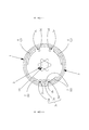
- FIG. 8 is a cross-sectional view showing a state in which the clutch device of the fourth embodiment is cut along a plane perpendicular to the output shaft 5.
- FIG. 9 is a cross-sectional view showing a state in which the clutch device of the fourth embodiment is cut along the BB plane in FIG.
- the lock spring step 3c is provided at both ends of the lock spring 3.
- a lock spring step 3c is provided in the middle.
- a pair of lock spring bent portions 3d provided near the middle portion of the lock spring 3 and a lock spring bottom portion 3e connecting the lock spring step portions 3c constitute a lock spring pressing piece in a gap between the pair of lock spring bent portions 3d. 7 is inserted.
- the lock spring bending portion 3d constituting the lock spring step portion 3c serves as a lock spring pressing side contact 3b (lock spring coupling fixed contact).
- the lock spring tension side contact 3 a is always provided at the end of the lock spring 3.
- the lock spring tension side contact 3a is provided on the lock spring bent portion 3d provided separately at the end of the lock spring 3.
- the lock spring bent portion 3d at the end of the lock spring 3 does not need to be provided with the lock spring bottom portion 3e to be the lock spring step portion 3c.
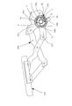
- FIG. 10 is a cross-sectional view showing a state where the ottoman device for a vehicle incorporating the clutch device of the present invention is cut along a plane perpendicular to the output shaft 5.
- the ottoman device for a vehicle shown in FIG. 10 includes the clutch device 100 of the present invention, a link mechanism 200, and an ottoman body 300.
- the clutch device 100 can be used in any of the above-described embodiments. However, in the ottoman device for a vehicle, an intermittent feed mechanism is not particularly required, and here, the clutch device 100 without the intermittent feed mechanism is used. Is used.
- a portion corresponding to the adjustment drum 2 is divided into a first clutch operation member 59a having a first lock spring operation piece 58a provided at the front end and a second clutch operation member having a second lock spring operation piece 58b provided at the front end. 59b.
- the link mechanism 200 is for supporting the ottoman main body 300 in a state where the ottoman main body 300 can be pulled forward from the lower side of the seat.
- the lock drum 1 is fixed to the first member 210
- the output shaft 5 is fixed to the second member 220.
- the portion corresponding to the adjustment drum 2 is configured by a plurality of clutch operation members (first clutch operation member 59a and second clutch operation member 59b).
- the clutch operating member can be one member.
- the application of the clutch device of the present invention described above is not limited, and can be employed in various applications. Especially, it can employ
Landscapes
- Engineering & Computer Science (AREA)
- Mechanical Engineering (AREA)
- Aviation & Aerospace Engineering (AREA)
- Transportation (AREA)
- General Engineering & Computer Science (AREA)
- Physics & Mathematics (AREA)
- Electromagnetism (AREA)
- Seats For Vehicles (AREA)
- Mechanical Operated Clutches (AREA)
- Braking Arrangements (AREA)
- One-Way And Automatic Clutches, And Combinations Of Different Clutches (AREA)
Abstract
L'invention porte sur un dispositif d'embrayage de haute sécurité, avec lequel l'état verrouillé peut être maintenu de manière fiable, même si une charge excessive est exercée sur un second élément. Ce dispositif d'embrayage est équipé de : un tambour de verrouillage (1) sur un premier élément ; une plaque d'arbre de sortie (6) sur un second élément ; un ressort de verrouillage (3) placé dans le tambour de verrouillage (1) ; et un tambour de réglage (2) disposé à l'intérieur du ressort de verrouillage (3). A l'état libre, le ressort de verrouillage (3) a un diamètre extérieur légèrement plus grand que le diamètre intérieur du tambour de verrouillage (1) et, sur le ressort de verrouillage, sont formées des parties épaulées de ressort de verrouillage (3c) qui comprennent une partie incurvée (3d) du ressort de verrouillage et une partie de fond (3e) du ressort de verrouillage. Des points de contact côté traction (3a) du ressort de verrouillage et des points de contact côté poussée (3b) du ressort de verrouillage sont formés respectivement sur le côté des parties incurvées de ressort de verrouillage (3d), sur lesquelles le diamètre du ressort de verrouillage (3) est contracté, et sur le côté sur lequel le diamètre est étendu. Des pièces d'actionnement de ressort de verrouillage (8), qui exercent une pression contre les points de contact côté traction (3a) du ressort de verrouillage, sont agencées sur le tambour de réglage (2) et des pièces de pression de ressort de verrouillage (7), qui exercent une pression contre les points de contact côté poussée (3b) du ressort de verrouillage, sont formées sur la plaque d'arbre de sortie (6).
Priority Applications (1)
| Application Number | Priority Date | Filing Date | Title |
|---|---|---|---|
| KR1020137025158A KR102025702B1 (ko) | 2012-04-19 | 2013-04-11 | 클러치 장치 |
Applications Claiming Priority (2)
| Application Number | Priority Date | Filing Date | Title |
|---|---|---|---|
| JP2012095984A JP5048883B1 (ja) | 2012-04-19 | 2012-04-19 | クラッチ装置 |
| JP2012-095984 | 2012-04-19 |
Publications (1)
| Publication Number | Publication Date |
|---|---|
| WO2013157471A1 true WO2013157471A1 (fr) | 2013-10-24 |
Family
ID=47189455
Family Applications (1)
| Application Number | Title | Priority Date | Filing Date |
|---|---|---|---|
| PCT/JP2013/060910 Ceased WO2013157471A1 (fr) | 2012-04-19 | 2013-04-11 | Dispositif d'embrayage |
Country Status (3)
| Country | Link |
|---|---|
| JP (1) | JP5048883B1 (fr) |
| KR (1) | KR102025702B1 (fr) |
| WO (1) | WO2013157471A1 (fr) |
Cited By (2)
| Publication number | Priority date | Publication date | Assignee | Title |
|---|---|---|---|---|
| DE102013223081B3 (de) * | 2013-11-13 | 2015-02-26 | Schaeffler Technologies Gmbh & Co. Kg | Schrittschaltwerk, insbesondere für eine Sitzverstellung eines Kraftfahrzeugsitzes |
| JP2020023229A (ja) * | 2018-08-06 | 2020-02-13 | 備前発条株式会社 | ばねロック機構 |
Families Citing this family (5)
| Publication number | Priority date | Publication date | Assignee | Title |
|---|---|---|---|---|
| WO2015019410A1 (fr) * | 2013-08-06 | 2015-02-12 | 備前発条株式会社 | Appareil d'ottomane |
| JP5736092B1 (ja) * | 2014-02-06 | 2015-06-17 | 備前発条株式会社 | クラッチ装置 |
| US9216667B1 (en) * | 2014-09-09 | 2015-12-22 | Ts Tech Co., Ltd. | Vehicle seat |
| JP6377538B2 (ja) * | 2015-01-16 | 2018-08-22 | トヨタ紡織株式会社 | 回転止め機構 |
| JP7445327B1 (ja) | 2022-11-07 | 2024-03-07 | 備前発条株式会社 | 回転ロック機構 |
Citations (8)
| Publication number | Priority date | Publication date | Assignee | Title |
|---|---|---|---|---|
| JPS59174428U (ja) * | 1983-05-09 | 1984-11-21 | 本田技研工業株式会社 | 逆転防止用メカニカルブレ−キ |
| JPS63162161U (fr) * | 1987-04-13 | 1988-10-24 | ||
| JPH0177142U (fr) * | 1987-11-12 | 1989-05-24 | ||
| JPH02127829U (fr) * | 1989-03-28 | 1990-10-22 | ||
| JP2000346167A (ja) * | 1999-06-01 | 2000-12-12 | Toto Kogyo Co Ltd | 出力軸を入力軸によって回転可能な回転伝達装置 |
| JP2001254765A (ja) * | 2000-03-10 | 2001-09-21 | Toyo Seat Co Ltd | ドラムブレーキ装置 |
| JP2002195323A (ja) * | 2000-12-27 | 2002-07-10 | Delta Kogyo Co Ltd | ブレーキドラム構造 |
| JP2007330480A (ja) * | 2006-06-14 | 2007-12-27 | T S Tec Kk | 車両用シート等のロック付き操作装置 |
Family Cites Families (4)
| Publication number | Priority date | Publication date | Assignee | Title |
|---|---|---|---|---|
| JP3814740B2 (ja) * | 1996-09-13 | 2006-08-30 | 三和シヤッター工業株式会社 | 電動シャッタ−用開閉機の手動操作装置 |
| JP4691249B2 (ja) | 2000-12-26 | 2011-06-01 | デルタ工業株式会社 | 操作軸の回転送り構造 |
| JP4925175B2 (ja) | 2006-07-07 | 2012-04-25 | テイ・エス テック株式会社 | 車両用シートのオットマン |
| JP2009168094A (ja) | 2008-01-15 | 2009-07-30 | Delta Kogyo Co Ltd | 操作軸の回転送り構造 |
-
2012
- 2012-04-19 JP JP2012095984A patent/JP5048883B1/ja not_active Expired - Fee Related
-
2013
- 2013-04-11 WO PCT/JP2013/060910 patent/WO2013157471A1/fr not_active Ceased
- 2013-04-11 KR KR1020137025158A patent/KR102025702B1/ko active Active
Patent Citations (8)
| Publication number | Priority date | Publication date | Assignee | Title |
|---|---|---|---|---|
| JPS59174428U (ja) * | 1983-05-09 | 1984-11-21 | 本田技研工業株式会社 | 逆転防止用メカニカルブレ−キ |
| JPS63162161U (fr) * | 1987-04-13 | 1988-10-24 | ||
| JPH0177142U (fr) * | 1987-11-12 | 1989-05-24 | ||
| JPH02127829U (fr) * | 1989-03-28 | 1990-10-22 | ||
| JP2000346167A (ja) * | 1999-06-01 | 2000-12-12 | Toto Kogyo Co Ltd | 出力軸を入力軸によって回転可能な回転伝達装置 |
| JP2001254765A (ja) * | 2000-03-10 | 2001-09-21 | Toyo Seat Co Ltd | ドラムブレーキ装置 |
| JP2002195323A (ja) * | 2000-12-27 | 2002-07-10 | Delta Kogyo Co Ltd | ブレーキドラム構造 |
| JP2007330480A (ja) * | 2006-06-14 | 2007-12-27 | T S Tec Kk | 車両用シート等のロック付き操作装置 |
Cited By (5)
| Publication number | Priority date | Publication date | Assignee | Title |
|---|---|---|---|---|
| DE102013223081B3 (de) * | 2013-11-13 | 2015-02-26 | Schaeffler Technologies Gmbh & Co. Kg | Schrittschaltwerk, insbesondere für eine Sitzverstellung eines Kraftfahrzeugsitzes |
| JP2020023229A (ja) * | 2018-08-06 | 2020-02-13 | 備前発条株式会社 | ばねロック機構 |
| WO2020031911A1 (fr) * | 2018-08-06 | 2020-02-13 | 備前発条株式会社 | Mécanisme de serrure à ressort |
| CN112088258A (zh) * | 2018-08-06 | 2020-12-15 | 备前发条株式会社 | 弹簧锁定机构 |
| US11828336B2 (en) | 2018-08-06 | 2023-11-28 | Bizen Hatsujo Co., Ltd. | Spring lock mechanism |
Also Published As
| Publication number | Publication date |
|---|---|
| KR102025702B1 (ko) | 2019-09-26 |
| JP5048883B1 (ja) | 2012-10-17 |
| JP2013224678A (ja) | 2013-10-31 |
| KR20140146991A (ko) | 2014-12-29 |
Similar Documents
| Publication | Publication Date | Title |
|---|---|---|
| JP5048883B1 (ja) | クラッチ装置 | |
| US20120240337A1 (en) | Two-stage actuating device for electric apparatus | |
| JP6298694B2 (ja) | 操作ハンドル機構及び荷重支持機構 | |
| KR102402990B1 (ko) | 차량용 시트의 높이 조절장치 | |
| CN106794784B (zh) | 用于后排座椅的调节设备以及座椅装置 | |
| WO2014077389A1 (fr) | Levier de commande, dispositif de siège et structure de section de commande | |
| CN106132809B (zh) | 转向盘的位置调节装置 | |
| US12497110B2 (en) | Vehicle spat device | |
| JP6614028B2 (ja) | シートクッション調整装置 | |
| JP2013185671A (ja) | 角度調節金具 | |
| KR101560986B1 (ko) | 차량용 시트 | |
| JP2009240350A (ja) | オットマン装置 | |
| KR20110054714A (ko) | 다이알타입 시트높이고정장치 | |
| JP2018039511A5 (fr) | ||
| JP5369866B2 (ja) | バッテリ搭載構造 | |
| JP2019043251A (ja) | スライド装置 | |
| JP2018090119A (ja) | シート用スライド装置 | |
| JP2015223974A (ja) | 車両のステアリング装置 | |
| US10471861B2 (en) | Conveyance seat | |
| JP2014136439A (ja) | 乗物用シート | |
| KR101117796B1 (ko) | 차량용 시트 높이 조절 장치 | |
| JP5766621B2 (ja) | 自動車用衝撃吸収シート | |
| KR101801973B1 (ko) | 푸시형 록킹 구조 | |
| JP5958199B2 (ja) | スライド装置 | |
| JP6379863B2 (ja) | ステアリングホイールの位置調節装置及びその製造方法 |
Legal Events
| Date | Code | Title | Description |
|---|---|---|---|
| ENP | Entry into the national phase |
Ref document number: 20137025158 Country of ref document: KR Kind code of ref document: A |
|
| 121 | Ep: the epo has been informed by wipo that ep was designated in this application |
Ref document number: 13777950 Country of ref document: EP Kind code of ref document: A1 |
|
| NENP | Non-entry into the national phase |
Ref country code: DE |
|
| 122 | Ep: pct application non-entry in european phase |
Ref document number: 13777950 Country of ref document: EP Kind code of ref document: A1 |