WO2020031911A1 - Mécanisme de serrure à ressort - Google Patents
Mécanisme de serrure à ressort Download PDFInfo
- Publication number
- WO2020031911A1 WO2020031911A1 PCT/JP2019/030569 JP2019030569W WO2020031911A1 WO 2020031911 A1 WO2020031911 A1 WO 2020031911A1 JP 2019030569 W JP2019030569 W JP 2019030569W WO 2020031911 A1 WO2020031911 A1 WO 2020031911A1
- Authority
- WO
- WIPO (PCT)
- Prior art keywords
- coil spring
- lock
- spring
- state
- drum
- Prior art date
- Legal status (The legal status is an assumption and is not a legal conclusion. Google has not performed a legal analysis and makes no representation as to the accuracy of the status listed.)
- Ceased
Links
Images


Classifications
-
- F—MECHANICAL ENGINEERING; LIGHTING; HEATING; WEAPONS; BLASTING
- F16—ENGINEERING ELEMENTS AND UNITS; GENERAL MEASURES FOR PRODUCING AND MAINTAINING EFFECTIVE FUNCTIONING OF MACHINES OR INSTALLATIONS; THERMAL INSULATION IN GENERAL
- F16D—COUPLINGS FOR TRANSMITTING ROTATION; CLUTCHES; BRAKES
- F16D51/00—Brakes with outwardly-movable braking members co-operating with the inner surface of a drum or the like
- F16D51/02—Brakes with outwardly-movable braking members co-operating with the inner surface of a drum or the like shaped as one or more circumferential band
-
- B—PERFORMING OPERATIONS; TRANSPORTING
- B60—VEHICLES IN GENERAL
- B60N—SEATS SPECIALLY ADAPTED FOR VEHICLES; VEHICLE PASSENGER ACCOMMODATION NOT OTHERWISE PROVIDED FOR
- B60N2/00—Seats specially adapted for vehicles; Arrangement or mounting of seats in vehicles
- B60N2/75—Arm-rests
- B60N2/763—Arm-rests adjustable
- B60N2/767—Angle adjustment
-
- B—PERFORMING OPERATIONS; TRANSPORTING
- B60—VEHICLES IN GENERAL
- B60N—SEATS SPECIALLY ADAPTED FOR VEHICLES; VEHICLE PASSENGER ACCOMMODATION NOT OTHERWISE PROVIDED FOR
- B60N2/00—Seats specially adapted for vehicles; Arrangement or mounting of seats in vehicles
- B60N2/80—Head-rests
- B60N2/806—Head-rests movable or adjustable
- B60N2/865—Head-rests movable or adjustable providing a fore-and-aft movement with respect to the occupant's head
-
- B—PERFORMING OPERATIONS; TRANSPORTING
- B60—VEHICLES IN GENERAL
- B60N—SEATS SPECIALLY ADAPTED FOR VEHICLES; VEHICLE PASSENGER ACCOMMODATION NOT OTHERWISE PROVIDED FOR
- B60N3/00—Arrangements or adaptations of other passenger fittings, not otherwise provided for
- B60N3/06—Arrangements or adaptations of other passenger fittings, not otherwise provided for of footrests
- B60N3/063—Arrangements or adaptations of other passenger fittings, not otherwise provided for of footrests with adjustment systems
-
- B—PERFORMING OPERATIONS; TRANSPORTING
- B60—VEHICLES IN GENERAL
- B60N—SEATS SPECIALLY ADAPTED FOR VEHICLES; VEHICLE PASSENGER ACCOMMODATION NOT OTHERWISE PROVIDED FOR
- B60N2/00—Seats specially adapted for vehicles; Arrangement or mounting of seats in vehicles
- B60N2/90—Details or parts not otherwise provided for
- B60N2/919—Positioning and locking mechanisms
- B60N2002/952—Positioning and locking mechanisms characterised by details of the locking system
Definitions
- the present invention relates to a spring lock mechanism.
- a spring lock mechanism is known as a mechanism that can adjust the angle of an armrest, an ottoman, or a headrest used for a seat of a vehicle or the like in a stepless manner (for example, see Patent Document 1).
- a frictional force is generated by tightening a lock drum provided inside a coil spring made of a spring wire having a rectangular cross section by the coil spring. This frictional force locks the armrest in one direction.
- the fixed end of the coil spring projects outward, is bent, and is attached to the rotation-side member at a position outside the lock drum. The free end is bent outward and a switching mechanism for switching between a locked state and an unlocked state is provided outside the lock drum.
- the fixed end of the coil spring is bent outside the coil spring and fixed outside the lock drum.
- the spring lock mechanism of Patent Document 3 locks the lock drum by a coil spring provided at a position inside the lock drum and releases the lock only when the lever is operated, and has a function of maintaining the unlocked state. It has a completely different design philosophy from the switching mechanism it has.
- JP-A-2004-147791 Japanese Patent No. 5890525 JP 2016-133138 A
- a burring portion (see, for example, a cylindrical portion 3a of Patent Literature 1) that holds a fixed portion of the coil spring is provided, and a part of the coil spring is wound.
- the load is shared by the burring section to prevent concentration of the load. This increases the number of turns to compensate for the decrease in the effective number of turns of the coil spring. As a result, there are problems such as an increase in the height of the lock drum or an increase in the diameter of the lock drum.
- the spring lock mechanism disclosed in Patent Document 3 locks the lock drum by a coil spring provided at a position inside the lock drum, but the design concept of the switching operation is completely different.
- the lock can be released only when the lever is pressed, and is a switching mechanism having no function of releasing the hand to maintain the unlocked state.
- An object of the present invention is to switch between a locked state and an unlocked and held state by rotation of a fixed side member and a rotation side member, while maintaining a required holding force at the time of locking.
- Another object of the present invention is to provide a spring lock mechanism that is highly safe, lightweight, and can be reduced in size.
- the object is to provide a first member composed of a fixed member, a second member composed of a rotating member that rotates with respect to the first member, and any one of the first member and the second member.
- a spring lock mechanism comprising: a spring; and a switching mechanism that rotates the second member with respect to the first member to switch between the locked state and the unlocked and held state.
- the coil spring has a winding outer diameter in a free state that is larger by 2 to 5% than an inner diameter of the lock drum, abuts on an inner peripheral surface of the lock drum, and has one end of the coil spring near the inside of the coil spring.
- Folded A fixed end is fixed at a position inside the lock drum, and the other end of the coil spring is a bent free end near the other end, and the rotation of the second member causes the spring wire of the coil spring to rotate.
- the coil spring expands in diameter and further presses the inner peripheral surface of the lock drum to lock the rotation by the frictional force, and the switching mechanism releases the lock.
- the problem is solved by providing a spring locking mechanism with an operation of increasing or decreasing the length of the coil spring in the state relative to the length of the coil spring in the locked state.
- the coil spring comes into contact with the inner peripheral surface of the lock drum. Accordingly, when a load due to frictional force is applied in a direction for locking the second member (a rotation direction for expanding the diameter of the coil spring), the spring wire is compressed in the longitudinal direction. With this load in the compression direction, unlike the tension direction, even if the spring wire is compressed and deformed, there is no fear of breaking or splitting. The difference in strength between the load in the compression direction and the load in the tensile direction with respect to breakage is particularly remarkable in a portion where the spring wire is bent.
- the distance from the center of rotation of the second member to the position where the frictional force is generated is longer by the diameter of the spring wire compared to the spring lock mechanisms of Patent Documents 1 and 2. That is, the holding force is advantageous from the principle of leverage. Thereby, the diameter of the drum can be reduced and the number of turns of the coil spring can be reduced.
- the switching between the lockable use state and the unlocked state is performed by the rotation of the second member, which involves displacement in the direction of increasing or shortening the length of the coil spring.
- the state can be maintained safely and reliably.
- the coil spring may be provided with a plurality of concave and convex portions that cross the spring wire of the coil spring at an outer peripheral position in contact with the lock drum, and may be grounded.
- the uneven portion is provided on the outer periphery of the coil spring, the forming can be easily performed with stable quality by rolling or the like. According to this configuration, the frictional force between the coil spring and the lock drum is greatly increased, the holding force is improved and the quality is stabilized, and the number of turns of the coil spring and the diameter of the lock drum can be reduced. it can.
- the switching mechanism switches between a locked state and an unlocked and held state, and at least a displacement cam that makes the length of the coil spring longer or shorter than the length of the locked state. And a holding portion for holding the displaced state of the coil spring, and a return cam for returning the held coil spring to its original locked state, so that the operation of lengthening or shortening the length of the coil spring is performed. Accordingly, the switching between the locked state and the unlocked and held state is performed by the rotation of the second member. As a result, the unlocked state can be maintained safely and reliably.
- the lock drum may be fixed to the second member, and the first member may be provided with a restricting portion for restricting the axial movement of the lock drum.
- the restricting portion of the first member restricts the movement of the second member in the axial direction (in the case of an armrest, a seat inner / outer direction, which will be described later), and a lock mechanism with less deformation and rattling is realized.
- FIG. 3 is a development view illustrating a relative positional relationship among a lock release cam, a return cam, a holding unit, a displacement cam, and a free end of a coil spring according to the first embodiment of the present invention. It is sectional drawing of the state which decomposed
- FIG. 1 shows a state in which a spring lock mechanism 10 and an armrest frame 31 according to a first embodiment of the present invention are covered with a skin 32 and the whole is integrated with a foamed resin (foam member) 34 injected into the inside of the skin 32.
- FIG. 3 is a cross-sectional view of the armrest 50 in a closed state.
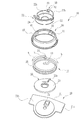
- FIG. 2 is an exploded perspective view of the spring lock mechanism 10 according to the first embodiment of the present invention.
- the lower limit of the angle adjustment range is 0 degree
- the upper limit is an angle adjustment in the range of about 30 to 50 degrees
- the vehicle that locks and selects an optimal position to be used The armrest 50 provided in the seat will be described as an example.
- the spring lock mechanism 10 includes a first member 20, a second member 30, a lock drum 11, a coil spring 12, a switching mechanism, and a stationary member. 40 (see FIG. 3).
- the second member 30 is configured by a rotation-side member that rotates with respect to the first member 20.
- the lock drum 11 is provided on one of the first member 20 and the second member 30. In the first embodiment, the lock drum 11 is provided on the armrest frame 31 of the second member 30.
- the coil spring 12 is provided at a position inside the lock drum 11.
- the coil spring 12 is fixed to the other member (the first member 20 in the first embodiment), abuts against the lock drum 11, and locks the one-way rotation of the second member 30 with respect to the first member 20 by a frictional force. It consists of a spring wire.
- the switching mechanism 40 (see FIG. 3) rotates the armrest frame 31 that is the second member 30 with respect to the first member 20 to switch between a locked state and a locked and released state.
- the first member 20 is composed of a plurality of fixed members including a mounting bracket 21, an inner drum 22, and a spring fixing plate 23.
- the spring fixing plate 23 includes a spring fixing portion 23a for fixing the fixed end 13 of the coil spring 12.
- the spring fixing plate 23 is provided between the mounting bracket 21 and the inner drum 22, and the fixed end 13 of the coil spring 12 (see FIG. 2) is connected to the mounting bracket 21 and the inner drum 22.
- the coil spring 12 is fixed by being sandwiched.
- the inner drum 22 is provided with a flange (regulating portion) 24, a displacement cam 42 constituting a switching mechanism 40 (see FIG. 3) described later, and a holding portion 43.
- the inner drum 22 has a cylindrical shape having a bottom portion 22a and an opening 22b, and a flange (restriction portion) 24 extends toward the outer periphery of the opening 22b.
- the displacement cam 42 and the holding portion 43 that constitute the switching mechanism 40 are provided in the opening 22b.
- the cylindrical inner drum 22 has been described as an example, but the present invention is not limited to this. That is, the member need not be a cylindrical shape as long as the member includes the flange (regulating portion) 24, the displacement cam 42, and the holding portion 43.
- the mounting bracket 21, the inner drum 22, and the spring fixing plate 23 are fixed to the seat frame 28 by bolts 29 so as not to rotate.
- the second member 30 is constituted by a rotation-side member such as the armrest frame 31 and the lock drum 11. As shown in FIG. 1, the second member 30 covers the spring lock mechanism 10 and the armrest frame 31 with a skin 32, and fills a gap between the armrest frame 31 and the skin 32 from an injection port 33 with a foamed resin 34 (polyurethane foam).
- the armrest 50 is formed by injecting and integrating the whole.
- a foam member intrusion prevention cover 35 for preventing the foam resin 34 (polyurethane foam) from entering when the foam resin 34 (polyurethane foam) is injected is provided along the lock drum 11 around the lock drum 11. Can be
- the lock drum 11 is provided on the second member 30 so as to rotate integrally with the armrest frame 31.
- the lock drum 11 has a cylindrical shape having openings at both ends, and the inner peripheral surface is arranged to face the outer peripheral surface of the inner drum 22.
- a flange 16 extends from an opening at one end of the lock drum 11 toward the inside of the lock drum 11.
- the flange 16 is provided with a lock release cam 41 and a return cam 44 constituting the switching mechanism 40, corresponding to the displacement cam 42 and the holding portion 43 provided on the inner drum 22.
- the lock drum 11 is arranged such that the flange 24 of the inner drum 22 overlaps with the flange 16 of the lock drum 11 in a direction along the axis R (hereinafter referred to as “axial direction”).
- the lock drum 11 is restricted from moving in the direction A and the direction B away from the seat frame 28 (hereinafter, referred to as “inward and outward directions of the seat”).
- the armrest 50 When a load is applied to the armrest 50 in the inward and outward directions of the seat, the armrest 50 slightly tilts inward and outward of the seat around the fixing portion between the seat frame 28 and the mounting bracket 21, and the flange 24 and the flange of the lock drum 11. 16 contacts. Further, the second member 30 and the mounting bracket 21 also abut. That is, the flange 24 of the inner drum 22 and the mounting member 21 serve as a restricting portion that restricts the movement of the lock drum 11 and the second member 30 in and out of the sheet (the same direction as the axial direction), and the lock drum 11 and the second member 30. Can be restricted from moving in and out of the seat. In addition, by receiving a load between the flange 24 and the mounting bracket 21, the strength in the sheet inner and outer directions is increased.
- the coil spring 12 has a fixed end 13, a free end 14, and an uneven portion 15.
- the outer diameter of the coil spring 12 is larger than the inner diameter of the lock drum 11 by about 2 to 5%, and in the assembled state shown in FIG. And is incorporated in the lock drum 11.
- the coil spring 12 comes into close contact with the inner peripheral surface of the lock drum 11 regardless of the presence or absence of a load.
- One end of the coil spring 12 is bent toward the inside of the coil spring 12, and is fixed to a spring fixing portion 23 a provided on a spring fixing plate 23, thereby forming a fixed end 13.
- the vicinity of the other end of the coil spring 12 is bent inside the coil spring 12 and becomes a free end 14 which is acted on by the unlocking cam 41, the displacement cam 42, and the return cam 44.
- a position on the outer periphery of the coil spring 12 a position in contact with the inner peripheral surface of the lock drum 11
- a plurality of concave and convex portions 15 are provided in a direction crossing the spring wire of the coil spring 12 (the same direction as the axial direction). It is flattened.
- the uneven portion 15 is formed by rolling or the like at the position on the outer periphery of the coil spring 12, and if the position is on the outer periphery, the forming can be easily performed with stable quality.
- the coil spring 12 shown in FIG. 1 and FIG. 2 has a switching mechanism 40 (see FIG. 3) so that the coil spring 12 can be displaced in a direction in which the length of the coil spring 12 is shortened. Is provided.
- the gap in the longitudinal direction of the coil spring 12 may be provided partially or distributed over the entire length.
- the fixed end portion 13 of the coil spring 12 having a large outer diameter is fixed to the spring fixing plate 23 of the first member 20, and is reduced in diameter and incorporated in the lock drum 11, and the outer peripheral surface of the coil spring 12 is fixed to the lock drum.
- the lock drum 11 rotates integrally with the rotation of the second member 30 by bringing the lock drum 11 into close contact with the inner peripheral surface of the lock member 11, the frictional force generated between the coil spring 12 and the lock drum 11 causes the rotation of the lock drum 11 to rotate.
- the spring 12 follows. Therefore, the coil spring 12 expands or contracts in diameter according to the rotation direction of the second member 30.
- the spring lock mechanism 10 in FIG. 2 is an exploded perspective view of a spring lock mechanism of an armrest 50 (see FIG. 1) for a left hand supporting a left hand of a seated person, and a winding direction of a coil spring 12 is left-handed.
- the coil spring 12 A force that follows the rotation of the lock drum 11 acts due to the frictional force therebetween.
- the direction of the force at this time is a direction in which the free end 14 is pushed to the left (see arrow a).
- the spring wire of the coil spring 12 is compressed in the longitudinal direction of the spring wire (the longitudinal direction when the spring wire is extended), the coil spring 12 expands in diameter, and the inner peripheral surface of the lock drum 11 is 12, the armrest 50 is locked from rotating downward.
- the frictional force between the coil spring 12 and the lock drum 11 causes the coil spring 12 to rotate the lock drum 11.
- the force that follows is applied.
- the direction of the force at this time is a direction in which the free end 14 is pulled rightward (see arrow b).
- the spring wire of the coil spring 12 is pulled in the longitudinal direction of the spring wire, the diameter of the coil spring 12 is reduced, and the force of the coil spring 12 on the inner peripheral surface of the lock drum 11 pressing the lock drum 11 is reduced.
- the upward rotation of the second member 30 is possible.
- the spring lock mechanism 10 illustrated in FIG. 2 includes a switching mechanism.
- FIG. 1 the state in which the one-way rotation of the second member 30 with respect to the first member 20 is locked, and the state in which the lock is released and held. Switching to the state can be performed. Although the details of the switching mechanism will be described later with reference to FIG. 3, the state where the lock is released and held is a state where the unlocked state is maintained. As described above, when a downward force is applied to the second member 30, the downward rotation of the armrest 50 is locked, but in the unlocked and held state, the unlocked state is maintained. Therefore, the second member 30 can be turned downward.
- the switching mechanism 40 shown in FIG. 3 includes a lock release cam 41, a displacement cam 42, a holding portion 43, and a return cam 44 in FIG.
- the unlocking cam 41 and the displacement cam 42 may be integrated (see FIG. 3C).
- the displacement cam 42 and the holding portion 43 are provided on the inner drum 22.
- the lock release cam 41 and the return cam 44 are provided on the lock drum 11.
- FIG. 3 is a development view illustrating a relative positional relationship among the unlocking cam 41, the displacement cam 42, the holding portion 43, the return cam 44, and the free end portion 14 when the armrest 50 is being rotated. It is.
- FIG. 3A is a diagram illustrating a state immediately before the second member 30 (see FIG. 1) of the armrest 50 reaches the upper limit position of the angle adjustment range (about 10 degrees before the upper limit position).
- the unlocking cam 41 provided on the lock drum 11 is approaching the free end 14 of the coil spring 12, and is in a state immediately before the unlocking cam 41 starts to contact the free end 14.
- the position of the unlocking cam 41 is set at a position where the unlocking cam 41 starts to contact the free end portion 14 when the second member 30 reaches the upper limit position of the angle adjustment range.
- FIG. 3B is a view showing a state immediately before the second member 30 of the armrest 50 is turned downward in the state where the second member 30 is unlocked and held at the upper limit position to reach the lower limit position.
- the return cam 44 provided on the lock drum 11 has started to contact the free end 14 of the coil spring 12.
- the position of the return cam 44 is set at a position where the return cam 44 starts to contact the free end portion 14 when the second member 30 reaches the lower limit position of the angle adjustment range.
- the lock drum 11 When the second member 30 is turned upward, the lock drum 11 also turns integrally therewith.
- the lock release cam 41 provided on the lock drum 11 is free end of the coil spring 12. Approaching the part 14 (see arrow c). After the unlocking cam 41 comes into contact with the free end portion 14, the free end portion 14 is pushed by the unlocking cam 41 and advances (see arrow d), whereby the coil spring 12 is reduced in diameter and the coil spring 12 The locked state due to the expansion is released.
- the free end portion 14 is displaced in the axially contracting direction by the displacement cam 42 provided on the inner drum 22 (see arrow e), and the coil spring 12 is locked in a length L ( The free end 14 is guided to the holding portion 43, and the coil spring 12 is held in a reduced length.
- FIG. 3C is a developed view of a case where the unlocking cam 41 and the shifting cam 42 are formed by one inclined cam 41 (42).
- the holding portion 43 may be provided on the side where the length L of the coil spring 12 is increased by reversing the positional relationship between the lock drum 11 and the inner drum 22 in the vertical direction. In such a case, the free end portion 14 of the coil spring 12 is held by the holding portion 43 by being displaced toward the longer length L of the coil spring 12.
- the spring lock mechanism 10 in FIG. 2 is based on the assumption that the armrest 50 for the left hand that supports the left hand of the seated person is used, and the winding direction of the coil spring 12 is left-handed. However, when the right hand armrest 50 that supports the right hand of the occupant is assumed, the winding direction of the coil spring 12 is clockwise.
- FIG. 4 is a sectional view of a spring lock mechanism 210 according to a second embodiment of the present invention.
- the coil spring 212 is fixed to the spring fixing plate 231 of the second member 230 constituted by a rotation-side member.
- the lock drum 211 is fixed to the first member 220 composed of a fixed member. That is, the spring lock mechanism 210 according to the second embodiment is different from the spring lock mechanism 210 in that the coil spring 212 is fixed to the second member 230 that is a rotating member, and the lock drum 211 is fixed to the first member 220 that is a fixed member. , Is different from the first embodiment.
- the lock drum 211 is incorporated in an empty space of the seat frame 220 on the fixed member side. This is advantageous in that the rotation side member can be made extremely thin.
- FIG. 5 is a sectional view of a spring lock mechanism 310 according to the third embodiment of the present invention.
- the spring lock mechanism 310 has its free end 314 bent outside the coil spring 312. Further, a part of the armrest frame 331 is molded into the lock drum 311.
- the flange (regulation portion) 324 provided on the inner drum 322 of the first member 320 extends to the outer peripheral surface of the lock drum 311 and is in contact with the entire periphery of the flange receiving portion 332 of another member fixed to the armrest frame 331. Is provided.
- the flange 324 so as to be in contact with the entire circumference of the flange receiving portion 332, the movement of the lock drum 311 and the second member 330 in and out of the sheet can be more strongly restricted. As a result, the strength in the sheet inward and outward directions is further increased.
- the holding portion 343 and the displacement cam 342 that constitute the switching mechanism 340 are provided on the flange 324. That is, in the spring lock mechanism 310 according to the third embodiment, the free end 314 is bent outside the coil spring 312, and the holding portion 343 and the displacement cam 342 are formed by the lock release cam and the return cam provided on the lock drum 311. This is different from the spring lock mechanism 10 in the first embodiment in that the spring lock mechanism 10 is provided on the outside. In addition, since a part of the armrest frame 331 is molded into the lock drum 311, the spring lock mechanism 310 can be made smaller and lighter.
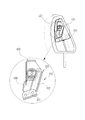
- FIG. 6 is a side view showing a state in which a spring lock mechanism 410 according to a fourth embodiment of the present invention is mounted on a headrest.
- a first member 420 which is a fixed side member of the spring lock mechanism 410
- the second member 430 serving as the rotation side member is fixed to the parallel link mechanism 433 including the second member 430, the third member 431, and the fourth member 432.
- the third member 431 of the parallel link mechanism 433 is fixed to the headrest stay 434.
- the headrest body 425 can be configured to be slidable forward (to the left in FIG. 6) while being locked from sliding backward (to the right in the drawing). On the other hand, if it exceeds the slide adjustment range, the lock is released, and the headrest main body 425 can be slid rearward to return to the initial position.
- FIG. 7 is a side view of an example showing a state in which a spring lock mechanism 510 according to a fifth embodiment of the present invention is mounted on an ottoman.
- a first member 520 which is a fixed member of the spring lock mechanism 510
- a second member 530 that is a rotation side member is fixed to a link member 532 that rotates the footrest main body 531 up and down. This locks the footrest body 531 from rotating downward in the angle adjustable range.
- the locked state and the unlocked state are switched and the lock is released. State can be maintained.
- the lock structure is locked by the rotation of the fixing member and the rotation member while maintaining the necessary holding force at the time of locking by pursuing the lock structure of the spring lock mechanism and the spring fixing structure. It is possible to switch between the locked state and the unlocked and held state, and to realize a spring lock mechanism that is highly safe, lightweight and compact.
Landscapes
- Engineering & Computer Science (AREA)
- Mechanical Engineering (AREA)
- General Engineering & Computer Science (AREA)
- Transportation (AREA)
- Aviation & Aerospace Engineering (AREA)
- Seats For Vehicles (AREA)
- Passenger Equipment (AREA)
- Braking Arrangements (AREA)
Abstract
La présente invention comprend : un tambour de verrouillage (11) disposé sur l'un ou l'autre d'un premier élément (20) ou d'un deuxième élément (30) ; un ressort hélicoïdal (12) fixé à l'autre desdits éléments, le ressort hélicoïdal (12) venant en contact avec le tambour de verrouillage (11) et verrouillant la rotation du deuxième élément (30) dans une direction par rapport au premier élément (20) par une force de frottement ; et un mécanisme de commutation qui fait tourner le deuxième élément (30) par rapport au premier élément (20) pour commuter entre un état verrouillé et un état déverrouillé et maintenu. Le ressort hélicoïdal (12) vient en contact avec la surface périphérique interne du tambour de verrouillage (11), et un fil à ressort du ressort hélicoïdal (12) est comprimé longitudinalement par la rotation du deuxième élément (30), moyennant quoi le ressort hélicoïdal (12) s'agrandit en diamètre et presse davantage contre la surface périphérique interne du tambour de verrouillage (11), et la rotation est verrouillée par la force de frottement de celui-ci. Le mécanisme de commutation inclut une action d'accompagnement consistant à augmenter ou à réduire la longueur du ressort hélicoïdal (12) dans l'état déverrouillé par rapport à la longueur du ressort hélicoïdal (12) dans l'état verrouillé.
Priority Applications (2)
| Application Number | Priority Date | Filing Date | Title |
|---|---|---|---|
| US17/049,422 US11828336B2 (en) | 2018-08-06 | 2019-08-02 | Spring lock mechanism |
| CN201980031148.2A CN112088258B (zh) | 2018-08-06 | 2019-08-02 | 弹簧锁定机构 |
Applications Claiming Priority (2)
| Application Number | Priority Date | Filing Date | Title |
|---|---|---|---|
| JP2018-147974 | 2018-08-06 | ||
| JP2018147974A JP6618582B1 (ja) | 2018-08-06 | 2018-08-06 | ばねロック機構 |
Publications (1)
| Publication Number | Publication Date |
|---|---|
| WO2020031911A1 true WO2020031911A1 (fr) | 2020-02-13 |
Family
ID=68836078
Family Applications (1)
| Application Number | Title | Priority Date | Filing Date |
|---|---|---|---|
| PCT/JP2019/030569 Ceased WO2020031911A1 (fr) | 2018-08-06 | 2019-08-02 | Mécanisme de serrure à ressort |
Country Status (4)
| Country | Link |
|---|---|
| US (1) | US11828336B2 (fr) |
| JP (1) | JP6618582B1 (fr) |
| CN (1) | CN112088258B (fr) |
| WO (1) | WO2020031911A1 (fr) |
Families Citing this family (1)
| Publication number | Priority date | Publication date | Assignee | Title |
|---|---|---|---|---|
| US11401039B2 (en) * | 2020-03-25 | 2022-08-02 | B/E Aerospace, Inc. | Angular armrest adjustment assembly |
Citations (4)
| Publication number | Priority date | Publication date | Assignee | Title |
|---|---|---|---|---|
| JPH01124434U (fr) * | 1987-09-30 | 1989-08-24 | ||
| JP2007185223A (ja) * | 2006-01-11 | 2007-07-26 | Namba Press Works Co Ltd | アームレスト装置 |
| WO2013157471A1 (fr) * | 2012-04-19 | 2013-10-24 | 備前発条株式会社 | Dispositif d'embrayage |
| JP2017178197A (ja) * | 2016-03-31 | 2017-10-05 | テイ・エス テック株式会社 | ワンウェイクラッチ |
Family Cites Families (12)
| Publication number | Priority date | Publication date | Assignee | Title |
|---|---|---|---|---|
| JPS5890525A (ja) | 1981-10-30 | 1983-05-30 | Mitsui Toatsu Chem Inc | ベンジルプロピルエ−テル誘導体の製造方法 |
| DE8629207U1 (de) * | 1986-11-03 | 1987-01-02 | R. Schmidt GmbH, 5940 Lennestadt | Drehhandhabe an Fahrzeugsitzen |
| FR2820375B1 (fr) * | 2001-02-06 | 2003-04-18 | Faurecia Sieges Automobile | Dispositif de fixation pour accoudoir amovible et dispositif d'assise comportant un tel dispositif de fixation |
| JP4089386B2 (ja) * | 2002-10-29 | 2008-05-28 | 日本発条株式会社 | アームレスト装置 |
| JP4446442B2 (ja) * | 2004-08-18 | 2010-04-07 | 備前発条株式会社 | アームレスト装置 |
| JP5489320B2 (ja) * | 2008-10-11 | 2014-05-14 | 備前発条株式会社 | アームレスト |
| CN102452330A (zh) * | 2010-10-21 | 2012-05-16 | 张晓冬 | 一种座椅平移调节装置 |
| US9714040B2 (en) * | 2011-07-26 | 2017-07-25 | Nabtesco Corporation | Unit brake |
| JP5586662B2 (ja) * | 2012-06-27 | 2014-09-10 | トックベアリング株式会社 | 逆入力遮断機構 |
| JP5654168B1 (ja) * | 2014-07-28 | 2015-01-14 | 備前発条株式会社 | アームレスト |
| JP6377538B2 (ja) | 2015-01-16 | 2018-08-22 | トヨタ紡織株式会社 | 回転止め機構 |
| CN108883717B (zh) | 2016-03-31 | 2021-02-26 | 提爱思科技股份有限公司 | 扶手 |
-
2018
- 2018-08-06 JP JP2018147974A patent/JP6618582B1/ja active Active
-
2019
- 2019-08-02 US US17/049,422 patent/US11828336B2/en active Active
- 2019-08-02 WO PCT/JP2019/030569 patent/WO2020031911A1/fr not_active Ceased
- 2019-08-02 CN CN201980031148.2A patent/CN112088258B/zh active Active
Patent Citations (4)
| Publication number | Priority date | Publication date | Assignee | Title |
|---|---|---|---|---|
| JPH01124434U (fr) * | 1987-09-30 | 1989-08-24 | ||
| JP2007185223A (ja) * | 2006-01-11 | 2007-07-26 | Namba Press Works Co Ltd | アームレスト装置 |
| WO2013157471A1 (fr) * | 2012-04-19 | 2013-10-24 | 備前発条株式会社 | Dispositif d'embrayage |
| JP2017178197A (ja) * | 2016-03-31 | 2017-10-05 | テイ・エス テック株式会社 | ワンウェイクラッチ |
Also Published As
| Publication number | Publication date |
|---|---|
| CN112088258B (zh) | 2022-01-11 |
| JP6618582B1 (ja) | 2019-12-11 |
| JP2020023229A (ja) | 2020-02-13 |
| US20210372493A1 (en) | 2021-12-02 |
| CN112088258A (zh) | 2020-12-15 |
| US11828336B2 (en) | 2023-11-28 |
Similar Documents
| Publication | Publication Date | Title |
|---|---|---|
| US7685903B2 (en) | Dual on-center column lock mechanism | |
| JP4063863B1 (ja) | ヘッドレスト | |
| WO2012096357A1 (fr) | Dispositif d'inclinaison de siège et dispositif de siège | |
| WO2010007885A1 (fr) | Dispositif d’inclinaison de siège pour véhicule | |
| JP2008272270A (ja) | 車両用ヘッドレスト | |
| CA2040624A1 (fr) | Dispositif de bascule a reglage continu pour sieges | |
| WO2020031911A1 (fr) | Mécanisme de serrure à ressort | |
| JP4446442B2 (ja) | アームレスト装置 | |
| WO2017169629A1 (fr) | Accoudoir | |
| JP5653175B2 (ja) | アームレスト装置及びアームレスト装置付きシート | |
| JP4566152B2 (ja) | 車両用シート装置 | |
| JP5890525B2 (ja) | アームレスト機構部ユニット | |
| JP5505317B2 (ja) | 車両用シート装置 | |
| JP7175063B1 (ja) | アームレスト | |
| KR20170061925A (ko) | 시트의 헤드레스트 경추 받침대 | |
| JP2007185223A (ja) | アームレスト装置 | |
| JP7280808B2 (ja) | ヘッドレスト | |
| JP6613406B2 (ja) | 乗物用シートにおけるシートバック又はアームレストのロック機構 | |
| JP2025140014A (ja) | 角度調節可能なアームレスト | |
| US20240209904A1 (en) | Brake module | |
| KR0131144Y1 (ko) | 암레스트 각도 조정장치 | |
| JP2005255022A (ja) | アームレスト装置 | |
| RU2126333C1 (ru) | Устройство для блокировки откидной спинки сиденья в транспортном средстве | |
| JPH07117538A (ja) | 可倒式リヤシートバックのロック構造 | |
| JPS5950538B2 (ja) | リクライニングシ−ト |
Legal Events
| Date | Code | Title | Description |
|---|---|---|---|
| 121 | Ep: the epo has been informed by wipo that ep was designated in this application |
Ref document number: 19846590 Country of ref document: EP Kind code of ref document: A1 |
|
| NENP | Non-entry into the national phase |
Ref country code: DE |
|
| 122 | Ep: pct application non-entry in european phase |
Ref document number: 19846590 Country of ref document: EP Kind code of ref document: A1 |