WO2013168480A1 - Feuille de fabrication de cartonnages, carton d'emballage, dispositif électrique et téléviseur - Google Patents
Feuille de fabrication de cartonnages, carton d'emballage, dispositif électrique et téléviseur Download PDFInfo
- Publication number
- WO2013168480A1 WO2013168480A1 PCT/JP2013/059306 JP2013059306W WO2013168480A1 WO 2013168480 A1 WO2013168480 A1 WO 2013168480A1 JP 2013059306 W JP2013059306 W JP 2013059306W WO 2013168480 A1 WO2013168480 A1 WO 2013168480A1
- Authority
- WO
- WIPO (PCT)
- Prior art keywords
- wall
- packaging box
- box
- display device
- bottom wall
- Prior art date
- Legal status (The legal status is an assumption and is not a legal conclusion. Google has not performed a legal analysis and makes no representation as to the accuracy of the status listed.)
- Ceased
Links
Images













Classifications
-
- B—PERFORMING OPERATIONS; TRANSPORTING
- B65—CONVEYING; PACKING; STORING; HANDLING THIN OR FILAMENTARY MATERIAL
- B65D—CONTAINERS FOR STORAGE OR TRANSPORT OF ARTICLES OR MATERIALS, e.g. BAGS, BARRELS, BOTTLES, BOXES, CANS, CARTONS, CRATES, DRUMS, JARS, TANKS, HOPPERS, FORWARDING CONTAINERS; ACCESSORIES, CLOSURES, OR FITTINGS THEREFOR; PACKAGING ELEMENTS; PACKAGES
- B65D5/00—Rigid or semi-rigid containers of polygonal cross-section, e.g. boxes, cartons or trays, formed by folding or erecting one or more blanks made of paper
- B65D5/42—Details of containers or of foldable or erectable container blanks
-
- B—PERFORMING OPERATIONS; TRANSPORTING
- B65—CONVEYING; PACKING; STORING; HANDLING THIN OR FILAMENTARY MATERIAL
- B65D—CONTAINERS FOR STORAGE OR TRANSPORT OF ARTICLES OR MATERIALS, e.g. BAGS, BARRELS, BOTTLES, BOXES, CANS, CARTONS, CRATES, DRUMS, JARS, TANKS, HOPPERS, FORWARDING CONTAINERS; ACCESSORIES, CLOSURES, OR FITTINGS THEREFOR; PACKAGING ELEMENTS; PACKAGES
- B65D5/00—Rigid or semi-rigid containers of polygonal cross-section, e.g. boxes, cartons or trays, formed by folding or erecting one or more blanks made of paper
- B65D5/42—Details of containers or of foldable or erectable container blanks
- B65D5/44—Integral, inserted or attached portions forming internal or external fittings
- B65D5/441—Reinforcements
- B65D5/445—Reinforcements formed separately from the container
-
- B—PERFORMING OPERATIONS; TRANSPORTING
- B65—CONVEYING; PACKING; STORING; HANDLING THIN OR FILAMENTARY MATERIAL
- B65D—CONTAINERS FOR STORAGE OR TRANSPORT OF ARTICLES OR MATERIALS, e.g. BAGS, BARRELS, BOTTLES, BOXES, CANS, CARTONS, CRATES, DRUMS, JARS, TANKS, HOPPERS, FORWARDING CONTAINERS; ACCESSORIES, CLOSURES, OR FITTINGS THEREFOR; PACKAGING ELEMENTS; PACKAGES
- B65D5/00—Rigid or semi-rigid containers of polygonal cross-section, e.g. boxes, cartons or trays, formed by folding or erecting one or more blanks made of paper
- B65D5/42—Details of containers or of foldable or erectable container blanks
- B65D5/64—Lids
- B65D5/643—Lids held in closed position by application of separate elements, e.g. clips, straps
-
- B—PERFORMING OPERATIONS; TRANSPORTING
- B65—CONVEYING; PACKING; STORING; HANDLING THIN OR FILAMENTARY MATERIAL
- B65D—CONTAINERS FOR STORAGE OR TRANSPORT OF ARTICLES OR MATERIALS, e.g. BAGS, BARRELS, BOTTLES, BOXES, CANS, CARTONS, CRATES, DRUMS, JARS, TANKS, HOPPERS, FORWARDING CONTAINERS; ACCESSORIES, CLOSURES, OR FITTINGS THEREFOR; PACKAGING ELEMENTS; PACKAGES
- B65D5/00—Rigid or semi-rigid containers of polygonal cross-section, e.g. boxes, cartons or trays, formed by folding or erecting one or more blanks made of paper
- B65D5/42—Details of containers or of foldable or erectable container blanks
- B65D5/64—Lids
- B65D5/66—Hinged lids
- B65D5/6602—Hinged lids formed by folding one or more extensions hinged to the upper edge of a tubular container body
- B65D5/6608—Hinged lids formed by folding one or more extensions hinged to the upper edge of a tubular container body the lid being held in closed position by self-locking integral flaps
-
- B—PERFORMING OPERATIONS; TRANSPORTING
- B65—CONVEYING; PACKING; STORING; HANDLING THIN OR FILAMENTARY MATERIAL
- B65D—CONTAINERS FOR STORAGE OR TRANSPORT OF ARTICLES OR MATERIALS, e.g. BAGS, BARRELS, BOTTLES, BOXES, CANS, CARTONS, CRATES, DRUMS, JARS, TANKS, HOPPERS, FORWARDING CONTAINERS; ACCESSORIES, CLOSURES, OR FITTINGS THEREFOR; PACKAGING ELEMENTS; PACKAGES
- B65D5/00—Rigid or semi-rigid containers of polygonal cross-section, e.g. boxes, cartons or trays, formed by folding or erecting one or more blanks made of paper
- B65D5/42—Details of containers or of foldable or erectable container blanks
- B65D5/64—Lids
- B65D5/66—Hinged lids
- B65D5/6602—Hinged lids formed by folding one or more extensions hinged to the upper edge of a tubular container body
- B65D5/6611—Hinged lids formed by folding one or more extensions hinged to the upper edge of a tubular container body the lid being held in closed position by application of separate elements, e.g. clips, hooks, elastics
-
- B—PERFORMING OPERATIONS; TRANSPORTING
- B65—CONVEYING; PACKING; STORING; HANDLING THIN OR FILAMENTARY MATERIAL
- B65D—CONTAINERS FOR STORAGE OR TRANSPORT OF ARTICLES OR MATERIALS, e.g. BAGS, BARRELS, BOTTLES, BOXES, CANS, CARTONS, CRATES, DRUMS, JARS, TANKS, HOPPERS, FORWARDING CONTAINERS; ACCESSORIES, CLOSURES, OR FITTINGS THEREFOR; PACKAGING ELEMENTS; PACKAGES
- B65D85/00—Containers, packaging elements or packages, specially adapted for particular articles or materials
- B65D85/68—Containers, packaging elements or packages, specially adapted for particular articles or materials for machines, engines or vehicles in assembled or dismantled form
-
- B—PERFORMING OPERATIONS; TRANSPORTING
- B65—CONVEYING; PACKING; STORING; HANDLING THIN OR FILAMENTARY MATERIAL
- B65D—CONTAINERS FOR STORAGE OR TRANSPORT OF ARTICLES OR MATERIALS, e.g. BAGS, BARRELS, BOTTLES, BOXES, CANS, CARTONS, CRATES, DRUMS, JARS, TANKS, HOPPERS, FORWARDING CONTAINERS; ACCESSORIES, CLOSURES, OR FITTINGS THEREFOR; PACKAGING ELEMENTS; PACKAGES
- B65D2585/00—Containers, packaging elements or packages specially adapted for particular articles or materials
- B65D2585/68—Containers, packaging elements or packages specially adapted for particular articles or materials for machines, engines, or vehicles in assembled or dismantled form
- B65D2585/6802—Containers, packaging elements or packages specially adapted for particular articles or materials for machines, engines, or vehicles in assembled or dismantled form specific machines, engines or vehicles
- B65D2585/6835—Containers, packaging elements or packages specially adapted for particular articles or materials for machines, engines, or vehicles in assembled or dismantled form specific machines, engines or vehicles audio-visual devices
- B65D2585/6837—Containers, packaging elements or packages specially adapted for particular articles or materials for machines, engines, or vehicles in assembled or dismantled form specific machines, engines or vehicles audio-visual devices tv or computers
Definitions
- the present invention relates to a box-making sheet for forming a packing box, a packing box, an electric device accommodated in the packing box, and a television receiver.
- a thin display device includes a panel-shaped display device having a display screen on the front side, and a stand for placing the display device on a desk or cabinet.
- the stand uses a stand column and a stand base.
- the stand column connects the display device and the stand base, and is provided in advance or attached to the back surface or the lower portion of the display device so that the axial length direction is along the vertical direction of the display device.
- the stand base is a portion that comes into contact with a desk or cabinet on which the display device is to be installed, and is provided in advance or attached to the bottom side end portion of the stand column.
- the packaging box When the display device is accommodated in the packaging box in a state where the display device and the stand are integrated, a wasteful space is likely to be generated inside the packaging box. Therefore, the packaging box tends to become unnecessarily large. Therefore, the display device is housed in a packaging box, for example, with a display device in which a stand column is integrally provided on the back surface and a stand base as separate bodies. In this case, since a useless space is hardly generated inside the packaging box, the packaging box can be reduced in size. However, in this case, the user of the display device needs to assemble the display device.
- the user takes out the display device and the stand base from the packing box.
- the user places the display device on a work place such as a table or a floor with the display screen facing downward.
- the user assembles the display device. Specifically, the user attaches the stand base to the stand column provided in the display device. Finally, the user places the display device on a desk or cabinet with the stand base facing downward.
- the packaging boxes described in Patent Documents 1 to 3 are used, the display device is assembled after the display device is taken out of the packaging box, so that the possibility of damage to the display device remains.
- the packaging boxes described in Patent Documents 1 to 3 are troublesome for general users because it is necessary to assemble a holding base for holding the display device in a vertical position before assembling the display device.
- the packaging box described in Patent Documents 1 and 2 is divided into two parts, the side having the top wall and the side having the bottom wall, and the holding base is assembled using the side having the bottom wall. The structure of the box is complicated.
- the packaging box described in Patent Document 4 accommodates the display device, the stand column, and the stand base separately.
- the packaging box is configured to be divided into two parts, a side having a top wall and a side having a bottom wall, in order to make it easy to take out the display device from the packaging box.
- the user assembles the stand by attaching the stand base to the stand column. Specifically, a screw hole is formed in the axial length direction on the end surface of the bottom end portion of the stand column, and the user screws the stand base to the bottom end portion of the stand column.
- the user places the packaging box containing the display device on the work place with the top wall side (that is, the top side of the display device) facing upward. Further, the user forms an opening in the side wall of the packaging box that accommodates the display device. At this time, the stand attachment position on the back of the display device appears. Next, the user attaches the stand to the display device that is still accommodated in the packaging box through the formed opening. More specifically, the user screws a stand column disposed along the back surface of the display device at a stand mounting position on the back surface of the display device in a direction intersecting the axial length direction.
- the user pulls out the side of the packaging box having the top wall upward, and takes out the display device from the side of the packaging box having the bottom wall. That is, when the packaging box described in Patent Document 4 is used, the display device is protected by the packaging box when the display device is assembled, and thus the display device is not damaged. Further, since the display device is held in the vertical posture by the packaging box while being accommodated in the packaging box, it is not necessary to assemble a holding base for holding the display device.
- the screwing operation is performed with the stand base stably placed on the bottom end of the stand column. It is not possible. Therefore, the user is forced to perform a difficult task of screwing the stand base to the bottom end portion of the stand column while holding the stand base by himself / herself. In order to eliminate such an inconvenience, it is conceivable to enclose a support for supporting the stand base in the packing box when the stand base is screwed. However, in this case, there is a problem that the number of parts increases.
- the packaging box described in Patent Document 4 has a structure that can be divided into two, like the packaging boxes described in Patent Documents 1 and 2, the structure of the packaging box is complicated.
- This invention is made
- the main objective forms two cuts over a bottom wall (or top wall) and a side wall, and the bottom wall (or top wall) and side wall are formed.
- One crease is formed in each, and the bottom wall (or top wall) is opened, the boundary between the bottom wall (or top wall) and the side wall between the two cuts, and the two creases
- An object is to provide a box, an electric device housed in a packing box, and a television receiver.
- a box manufacturing sheet includes a top wall and a bottom wall, and a continuous side wall on at least one of the top wall and the bottom wall, the one being a hinge lid centering on a boundary portion with the side wall.
- a box-making sheet for forming a packing box that can be opened in a shape, two cuts are formed between the first part to be the one side and the second part to be the side wall. And one each for the first part and the second part located between the two cuts, parallel to the boundary part and equidistant from the boundary part, A box-making sheet comprising two creases for mountain-folding on the side to be inside.
- the box manufacturing sheet according to the present invention is characterized in that a reinforced portion that reinforces a crease formed in at least the second portion from the side that should be outside the packing box is disposed.
- the box making sheet according to the present invention is characterized in that the reinforcing portion has a tape shape that is affixed from the outside to the formation position of the fold.
- the box making sheet according to the present invention is characterized in that a cut line for providing an opening is formed between the two cuts.
- a box manufacturing sheet includes a top wall and a bottom wall, and a continuous side wall on at least one of the top wall and the bottom wall, the one being a hinge lid centering on a boundary portion with the side wall.
- a box-making sheet for forming a packing box that can be opened in a shape, two cuts are formed between the first part to be the one side and the second part to be the side wall. And one each for the first part and the second part located between the two cuts, parallel to the boundary part and equidistant from the boundary part, Two folds for mountain fold or valley fold are provided on the side to be inside, and one of the folds formed in the first portion and the folds formed in the second portion is mountain-folded And the other is for valley folding. That.
- the box making sheet according to the present invention is a side that should be outside the packing box, with the fold formed in the first portion and the fold formed in the one of the folds formed in the second portion.
- a first reinforcing portion that is reinforced from the side and a second reinforcing portion that is reinforced from the side that should be the inside of the packing box are disposed on the other side.
- the first reinforcing portion is formed in a tape shape that is affixed from outside to the formation position of the fold, and the second reinforcing portion is formed of the fold. It is characterized by having a tape shape that is attached to the position from the inside.
- the packaging box according to the present invention includes a top wall and a bottom wall, and a continuous side wall on at least one of the top wall and the bottom wall, and the one has a hinge lid shape centering on a boundary portion with the side wall.
- An openable packaging box is characterized in that it is formed using the box making sheet according to any one of claims 1 to 7.
- An electrical device includes an electrical device and a leg portion attached to the electrical device, and the electrical device integrally includes a mounted portion to which the leg portion is to be attached on a bottom side thereof.
- the electric device and the leg are separately housed in the packaging box according to claim 8, and the electric device has a top side of the electric device arranged on the other side of the top wall and the bottom wall.
- the bottom side of the attached part is arranged on the one side of the top wall and the bottom wall, and the top side of the attached part of the electric equipment housed in the packaging box
- the arrangement position corresponds to the formation position in the vertical direction of the fold formed on the side wall.
- the separation distance between the two cuts is a dimension in a direction along the boundary portion of the leg portion when the leg portion is attached to the electric device accommodated in the packing box. It is formed according to.
- the packing box is formed using the box-making sheet according to the present invention, and the opening is configured to allow a part or all of the leg portion to be inserted.
- the television receiver includes a display device, a leg attached to the display device, and a reception unit that receives the television broadcast, based on the television broadcast received by the reception unit, An image is displayed on the display device, and the display device is a television receiver integrally including a mounted portion to which the leg portion is to be attached on the bottom side thereof, and at least the display device and the leg portion.
- the display device is arranged such that a top side of the display device is disposed on the other side of the top wall and the bottom wall, and a bottom of the attached portion is provided.
- the side is arranged on the one side of the top wall and the bottom wall, and is formed on the side wall in the top-down direction of the attached portion of the display device housed in the packaging box and on the side wall And the formation position of the fold in the vertical direction Characterized in that it is compliant.
- the electric device according to the present invention and the television receiver according to the present invention are housed in the packaging box according to the present invention, and are assembled using the packaging box according to the present invention.
- the packaging box according to the present invention is formed using the box making sheet according to the present invention.
- the electric device includes an electric device and a leg portion attached to the electric device.
- the electric device has a mounted portion integrally, and a leg portion is mounted on the bottom side of the mounted portion.
- the television receiver includes a display device, legs attached to the display device, and a receiving unit. Since the display device and the leg included in the television receiver correspond to the electric device and the leg included in the electric device, the electric device will be described below.
- the electric device is accommodated in the packaging box with the electric device and the leg portion as separate bodies.
- the top side of the electric device is arranged on the top wall side (or the bottom wall side) of the packaging box. Therefore, when the packaging box is placed with the bottom wall (or the top wall) facing upward, the electrical equipment is arranged in a vertical posture that is upside down inside the packaging box.
- the bottom side of the mounted portion of the electric device is arranged on the bottom wall side (or the top wall side). Therefore, if the bottom wall (or top wall) is opened, the bottom side of the attached portion appears.
- the packaging box includes a continuous side wall (hereinafter referred to as a continuous side wall) on the bottom wall.
- the continuous side wall may be continuous only on the bottom wall of the top wall and the bottom wall, or may be continuous on the top wall.
- seat for box making is provided respond
- the bottom wall is opened like a hinge lid around a boundary portion (hereinafter simply referred to as a boundary portion) between the bottom wall and the continuous side wall.
- the boundary portion is folded into the outside of the packaging box.
- the valley fold on the outside of the packaging box is to fold the packaging box so that the outer surface side is a valley and the inner surface side is a mountain.
- the packaging box includes two cuts and a fold.
- Each of the two cuts is formed across the bottom wall and the continuous side wall.
- the two folds are both formed between the two cuts.
- one crease is formed on each of the bottom wall and the continuous side wall.
- Each of the two folds is parallel to the boundary portion, and the distance from the boundary portion to each other is equal.
- the formation position in the vertical direction of the crease formed in the continuous side wall corresponds to the arrangement position in the vertical direction of the mounted portion of the electrical equipment housed in the packaging box.
- the operator takes out the leg portion from the opening on the bottom wall side of the packaging box.
- the operator folds the boundary portion located between the two cuts into the inner side of the packing box, and folds the two folds into the inner side of the packing box.
- a step portion constituted by the bottom wall and the continuous side wall located between the two cuts is formed in the packaging box.
- the valley fold (or mountain fold) inside the packing box is to fold the packing box so that the inner surface side is a valley (or mountain) and the outer surface side is a mountain (or valley).
- the formation position in the vertical direction of the crease formed in the side wall that is, the arrangement position of the continuous side wall constituting the stepped portion is the arrangement in the vertical direction of the mounted part of the electrical equipment accommodated in the packaging box. Corresponds to the position. Therefore, when the operator lays the leg portion on the step portion and the bottom side of the attached portion, the leg portion is stably supported by the step portion and the bottom side of the attached portion. In this manner, the operator attaches the leg part to the attachment part of the electric device in a state where the leg part is stably placed horizontally.
- the reinforcing portion that reinforces the crease formed at least on the continuous side wall from the outside of the packaging box is disposed in the packaging box.
- the portion where the fold is formed has lower strength than the portion where the fold is not formed. That is, the part where the fold is formed is more easily damaged than the other part. Therefore, the reinforcing part reinforces the crease from the outside of the packaging box. For this reason, the damage of the part in which the crease
- the reinforcing portion may hinder the fold from being folded into the inside of the packaging box.
- the tape-shaped reinforcing portion is arranged in the packing box.
- the tape-shaped reinforcing part can be prepared at low cost using, for example, a commercially available adhesive tape (gum tape or vinyl tape). Moreover, it is easy to affix a tape-shaped reinforcement part on the formation position of a crease
- a cut line is formed between the two cuts.
- an opening through which a part or all of the leg portion can be inserted is provided on the inner wall of the step portion.
- this opening is used to insert the leg portion from the outside to the inside of the step portion through the opening, further move the leg portion laterally, and lay the leg portion on the step portion and the bottom side of the attached portion.
- this opening is formed, for example, when the separation distance between the stepped portion and the bottom side of the mounted portion is insufficient as compared with the dimension of the leg portion, and the leg portion is partially brought out of the stepped portion through the opening. Can be used to project.
- the worker who performs the assembly work of the electric device first places the packaging box with the bottom wall facing upward. Next, the worker opens the bottom wall. At this time, the mounted portion of the electric device appears. Next, the operator takes out the leg portion from the opening on the bottom wall side of the packaging box.
- the operator folds the bottom wall into the inside of the packaging box through the opened bottom opening, and brings the bottom wall into contact with the continuous side wall.
- the boundary portion is valley-folded inside the packaging box.
- an operator folds a bottom wall to the exterior of a packaging box, and makes a bottom wall contact a continuous side wall.
- the boundary portion is mountain-folded inside the packing box.
- the formation position in the vertical direction of the crease formed in the side wall that is, the arrangement position of the continuous side wall constituting the stepped portion is the arrangement in the vertical direction of the mounted part of the electrical equipment accommodated in the packaging box. Corresponds to the position. Therefore, when the operator lays the leg portion on the step portion and the bottom side of the attached portion, the leg portion is stably supported by the step portion and the bottom side of the attached portion. In this manner, the operator attaches the leg part to the attachment part of the electric device in a state where the leg part is stably placed horizontally.
- the first reinforcing portion that reinforces the fold for folding the mountain from the outside of the packaging box, and the second reinforcing portion that reinforces the fold for valley folding from the inside of the packaging box It is placed in the packing box.
- the portion where the fold is formed has lower strength than the portion where the fold is not formed. That is, the part where the fold is formed is more easily damaged than the other part. Therefore, the first or second reinforcing portion reinforces the crease from the outside or the inside of the packaging box. For this reason, the damage of the part in which the crease
- the tape-like first and second reinforcing portions are arranged in the packing box.
- the tape-like first and second reinforcing portions can be prepared at low cost using, for example, a commercially available adhesive tape. Moreover, it is easy to affix a tape-shaped reinforcement part on the formation position of a fold. As a result, the manufacturing cost of the packaging box can be reduced while improving the strength of the packaging box.
- the separation distance between the two cuts is formed in accordance with the dimension in the direction along the boundary portion of the leg portion when the leg portion is attached to the electrical device accommodated in the packaging box. . Therefore, the dimension along the boundary portion of the step portion corresponds to the dimension along the boundary portion of the leg portion. Therefore, if the leg is placed on the step, the leg is positioned in the direction along the boundary portion. As a result, positioning of the legs when assembling the electric device is facilitated, so that workability can be improved.
- the leg portion can be stably placed on the stepped portion and the attached portion described above,
- the leg portion can be easily attached to the attached portion of the electric device. That is, the operator can easily assemble the electric device.
- the step portion is formed by folding the bottom wall and the continuous side wall of the packaging box. Therefore, an object such as a support for supporting the leg portion is unnecessary. As a result, the number of parts does not increase only for assembling the electric device.
- the packaging box has a simple configuration. For this reason, the manufacturing cost of a packaging box can be reduced.
- the electric device can be assembled in a state where the electric device accommodated in the packing box is held in the vertical posture. In other words, the electric device at the time of assembling the electric device can be protected by the packing box. Therefore, there is no possibility that the electric device is damaged when the electric device is assembled. In addition, the work space can be saved as compared with the case where the electric device is assembled with the electric device held in the horizontal position.
- the electrical device is accommodated in the packaging box with the electrical device and the leg part as separate bodies, the electrical device is packaged as compared with the case where the electrical device and the leg part are accommodated in the packaging box.
- the box can be miniaturized.
- the electric device and the leg are included, it is easier to manage or store the separate electric device and the leg than when the electric device and the leg are housed in separate packaging boxes. And so on.
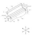
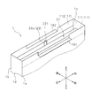
- FIG. 3 It is a perspective view which shows the external appearance of the packaging box which concerns on Embodiment 3 of this invention. It is an expanded view of the inner surface side of a packaging box. It is a perspective view for demonstrating the assembly procedure of the electric apparatus which concerns on Embodiment 3 of this invention (Removal of a bottom side box, and taking out of a stand base). It is a perspective view (formation of a step part) for demonstrating the assembly procedure of an electric apparatus. It is a top view (horizontal stand base stand) for demonstrating the assembly procedure of an electric apparatus. It is a partial expanded longitudinal cross-sectional view (horizontal mounting and attachment of a stand base) for demonstrating the assembly procedure of an electric apparatus.
- FIG. 4 It is a perspective view which shows the external appearance of the packaging box which concerns on Embodiment 4 of this invention. It is an expanded view of the inner surface side of a packaging box. It is a perspective view for the assembly procedure of the electric apparatus which concerns on Embodiment 4 of this invention (on the way of opening of a bottom wall). It is a perspective view (opening of a bottom wall, taking out of a stand base, and formation of a step part) for demonstrating the assembly procedure of the electric apparatus which concerns on Embodiment 4 of this invention. It is a partial expanded longitudinal cross-sectional view (horizontal mounting and attachment of a stand base) for demonstrating the assembly procedure of an electric apparatus.
- FIG. 5 It is a perspective view which shows the external appearance of the packaging box which concerns on Embodiment 5 of this invention. It is an expanded view of the inner surface side of a packaging box. It is an expanded view of the outer surface side of a packaging box. It is a perspective view (opening of a bottom wall and taking out of a stand base) for demonstrating the assembly procedure of the electric apparatus which concerns on Embodiment 5 of this invention. It is a perspective view (formation of a step part) for demonstrating the assembly procedure of an electric apparatus. It is a top view (horizontal stand base stand) for demonstrating the assembly procedure of an electric apparatus. It is a partial expanded longitudinal cross-sectional view (horizontal mounting and attachment of a stand base) for demonstrating the assembly procedure of an electric apparatus.
- FIG. 6 It is a perspective view which shows the external appearance of the packaging box which concerns on Embodiment 6 of this invention. It is an expanded view of the inner surface side of a packaging box. It is an expanded view of the outer surface side of a packaging box. It is a perspective view (opening of a bottom wall and taking out of a stand base) for demonstrating the assembly procedure of the electric apparatus which concerns on Embodiment 6 of this invention. It is a perspective view (formation of a step part) for demonstrating the assembly procedure of an electric apparatus. It is a top view (horizontal stand base stand) for demonstrating the assembly procedure of an electric apparatus. It is a partial expanded longitudinal cross-sectional view (horizontal mounting and attachment of a stand base) for demonstrating the assembly procedure of an electric apparatus.
- FIG. 1 a front wall (side wall) 1a, a rear wall 1b, a right wall 1c, a left wall 1d, a top wall 1e, and a bottom wall 1f, which will be described later, of the packaging box 1 are A front part, a rear part, a right part, a left part, a lower part, and an upper part are formed.
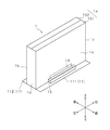
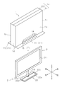
- FIG. 1 is a perspective view showing an appearance of a packaging box 1 according to Embodiment 1 of the present invention.
- FIG. 1 is also a perspective view for explaining an assembly procedure of the electric device according to the first embodiment of the present invention.
- the packaging box 1 has a rectangular parallelepiped appearance.
- the packaging box 1 has a rectangular front wall 1a, rear wall 1b, right wall 1c, left wall 1d, top wall 1e, and bottom wall 1f.
- FIG. 2 is a rear view showing the arrangement of the display device 21 and the stand base 22 (each described later) housed in the packaging box 1.
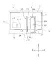
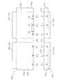
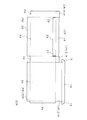
- FIG. 3 and 4 are development views of the inner surface side and the outer surface side of the packaging box 1. These are also diagrams showing a box-making sheet 100 for forming the packaging box 1.
- FIG. 3 shows the side to be the inner surface side (and outer surface side) of the packaging box 1 in the box manufacturing sheet 100.
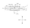
- FIGS. 5, 6, 9, and 10 are diagrams for explaining the assembly procedure of the electric device.
- FIGS. 5, 6, 9, and 10 are perspective views
- FIG. 7 is a top view
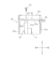
- FIG. It is the partial expansion longitudinal cross-sectional view which expanded the upper part.
- FIG. 1 shows the placement of the packing box 1 upside down
- FIG. 5 shows the opening of the bottom wall 1f and the removal of the stand base 22
- FIG. 6 shows the formation of a step portion 15 to be described later.
- 7 represents the horizontal mounting of the stand base 22
- FIG. 8 represents the horizontal mounting and attachment of the stand base 22
- FIG. 9 represents the placement of the packaging box 1 with the bottom wall 1f open.
- 10 represents extraction of the packaging box 1.
- the display apparatus 2 is illustrated as an electrical apparatus.
- the display device 2 is configured as a television receiver.
- the display device 2 includes a display device (electric device) 21 and a stand base (leg portion) 22.
- the display device 21 has a thin rectangular panel shape.
- the display device 21 uses a liquid crystal display panel or a plasma display panel, and has a display screen 211 on the front.
- the display device 21 includes a receiving unit 212 and a signal processing unit 213.
- the display device 21 displays an image based on the television broadcast received by the receiving unit 212.
- the receiving unit 212 receives a television broadcast from the outside via an antenna (not shown) and extracts a broadcast signal from the received television broadcast.
- the signal processing unit 213 outputs video data by performing predetermined signal processing on the broadcast signal extracted by the receiving unit 212.
- the display device 21 displays a video based on the video data output from the signal processing unit 213 on the display screen 211.
- the receiving unit 212 and the signal processing unit 213 may be externally attached to the display device 21. In this case, the receiving unit 212 and the signal processing unit 213 may not be included in the packaging box 1.
- a stand column 23 is integrally provided on the back surface of the display device 21.
- the stand column 23 has a columnar shape in which the axial length direction is in the vertical direction (vertical direction in the drawing) of the display device 21.
- the top end of the stand column 23 and the center in the vertical direction are arranged along the back surface of the display device 21.
- a bottom end (attached part) 23a of the stand column 23 protrudes from the display device 21 to the outside (the lower side in FIGS. 2 and 10).
- a screw hole 231 is formed in the axial length direction on the end surface of the bottom end 23 a of the stand column 23.
- a screw 24 can be screwed into the screw hole 231.
- the stand base 22 is a plate member having a rectangular shape in plan view.
- the stand base 22 has two long side portions 22a and 22b and two short side portions 22c and 22d that connect the long side portions 22a and 22b.
- an insertion hole 221 into which the screw 24 can be inserted is formed at the center position in the longitudinal direction of the long side portion 22b.
- the length of each of the short sides 22c and 22d is sufficiently longer than the thickness of the display device 21.
- the display device 21, the stand base 22, and the screws 24 are accommodated in the packaging box 1 as separate bodies. For this reason, the operator needs to assemble the display device 2 by attaching the stand base 22 to the display device 21 using the screws 24.
- the operator places the long side portions 22a and 22b of the stand base 22 on the front side and the rear side, places the short side portions 22c and 22d on the right side and the left side, and the top side of the long side portion 22b.
- the screw 24 is inserted into the insertion hole 221 from the bottom surface side of the stand base 22, and the screw 24 is screwed into the screw hole 231 of the stand column 23.
- the long side portion 22 b of the stand base 22 is sandwiched between the screw head of the screw 24 and the bottom side end portion 23 a of the stand column 23.
- the display device 21 and the stand base 22 are connected via the stand column 23.
- the present embodiment uses the packaging box 1 as described later.
- the display device 21 and the stand base 22 accommodated in the packaging box 1 are covered with a cover (not shown) using a foam sheet or a vinyl sheet. Between the inner surface of the packaging box 1 and the display device 21 and the stand base 22, and between the display device 21 and the stand base 22, a cushioning material (not shown) made of foamed polystyrene or bubble cushioning material is arranged. Has been.
- the display device 21 and the stand base 22 are arranged in a predetermined posture at a predetermined position inside the packaging box 1 by being held by a cushioning material. Therefore, it is possible to suppress the display device 21 or the stand base 22 from being unnecessarily shaken, colliding with another object, or being damaged inside the packaging box 1.
- the front (and back) faces the front wall 1a (and the rear wall 1b) of the packaging box 1
- the top side (and bottom side) is the ceiling wall of the packaging box 1.
- 1e (and bottom wall 1f) is arranged in a vertical posture so as to face. Therefore, the bottom side end 23a of the stand column 23 is arranged on the bottom wall 1f side.
- the stand base 22 accommodated in the packaging box 1 is arranged in a vertical posture between the back surface of the display device 21 and the rear wall 1b.
- the screws 24 accommodated in the packaging box 1 are arranged in appropriate gaps inside the packaging box 1 in a state accommodated in a small bag (not shown).
- the display device 21, the stand base 22, and the screws 24 are bundled, they can be easily managed or stored as compared with the case where they are housed in separate packing boxes. it can. Even if the screw 24 is a commercially available general part, it is not necessary for the operator to prepare the screw 24 separately, which is highly convenient for the operator.
- the thickness of the packaging box 1 is longer than the length of the stand base 22 before and after (that is, the length of each of the short side portions 22c and 22d). There must be.
- the thickness of the packaging box 1 may be longer than the thickness of the display device 21 and may be shorter than the length before and after the stand base 22. That is, the packaging box 1 can be configured compactly in the thickness direction.
- the packaging box 1 is assembled by folding a box-making sheet 100 cut into a shape as shown in FIGS. 3 and 4.
- the box manufacturing sheet 100 is made of a single cardboard.
- the box manufacturing sheet 100 includes a portion to be the front wall 1a (first portion), a portion to be the rear wall 1b, a portion to be the bottom wall 1f (second portion), and a rectangular assembling allowance. 1 g.
- the portion to be the front wall 1a, the portion to be the rear wall 1b,..., And the portion to be the bottom wall 1f are also referred to as the front wall 1a, the rear wall 1b,.
- the ceiling wall 1e has two joint ceiling wall pieces 101 and 102.
- the bottom wall 1 f has two joint bottom wall pieces 111 and 112.
- a right wall 1c, a left wall 1d, one top wall piece 101, and one bottom wall piece 111 are continuously provided on the front wall 1a.
- An assembly allowance 1g, a right wall 1c, the other top wall piece 102, and the other bottom wall piece 112 are continuously provided on the rear wall 1b.
- a boundary portion with the front wall 1a or the rear wall 1b is referred to as a base end portion, and one side portion parallel to the base end portion is referred to as a tip end portion.
- the packaging box 1 has cut lines 12 and 12 and fold lines 131 and 132.
- the cut lines 12, 12 are indicated by thick lines, and the fold lines 131, 132 are indicated by alternate long and short dash lines. 3 and FIG. 4, a portion to be mountain-folded toward the outside of the packaging box 1 when the packaging box 1 is assembled is indicated by a broken line.
- Each cut 12 is formed across the front wall 1a and the bottom wall piece 111.
- the cut 12 is formed by making a cut through the corrugated cardboard constituting the front wall 1a and the bottom wall piece 111.
- the longitudinal direction of the cut 12 is orthogonal to the base end portion of the bottom wall piece 111. That is, the cuts 12 and 12 are parallel to each other.
- the length from the end on the front wall 1a side of the cut 12 to the base end of the bottom wall piece 111 is equal to the length from the end on the bottom wall 1f side of the cut 12 to the base end of the bottom wall piece 111.
- the vertical position of the end of the cut 12 on the front wall 1a side is the vertical position where the end surface of the bottom end 23a of the stand column 23 is arranged when the display device 21 is accommodated in the packaging box 1. It corresponds to.
- the separation distance between the cuts 12, 12 is the length of the long side portion 22a (ie, the bottom wall piece 111 of the stand base 22 when the stand base 22 is attached to the display device 21 accommodated in the packaging box 1). Corresponding to the dimension along the base end).
- the center position in the separation direction between the cuts 12 and 12 corresponds to the position in the left-right direction where the end surface of the bottom side end 23a of the stand column 23 is arranged when the display device 21 is accommodated in the packaging box 1. .
- the crease 131 is formed by connecting the ends of the cuts 12, 12 on the front wall 1a side.
- the fold line 132 is formed by connecting ends of the cut lines 12 and 12 on the bottom wall piece 111 side. That is, the fold line 131 is formed on the front wall 1 a located between the cut lines 12 and 12, and the fold line 132 is formed on the bottom wall piece 111 located between the cut lines 12 and 12.
- the fold lines 131 and 132 are parallel to each other, and the lengths from the fold lines 131 and 132 to the base end of the bottom wall piece 111 are equal. Further, the formation position of the fold line 131 in the top-to-bottom direction corresponds to the top-to-bottom position where the end surface of the bottom side end portion 23 a of the stand column 23 is arranged when the display device 21 is accommodated in the packaging box 1.
- the crease 131 is formed by cutting the inner surface and the center of the corrugated cardboard constituting the front wall 1a.
- the fold line 132 is formed by cutting the inner surface and the center of the corrugated cardboard constituting the bottom wall piece 111. For this reason, the front wall 1a and the bottom wall piece 111 can be easily mountain-folded inward at the positions where the fold lines 131 and 132 are formed.
- the formation positions of the folds 131 and 132 in the front wall 1a and the bottom wall piece 111 are lower in strength than other portions. For this reason, the tape-shaped reinforcement parts 14 and 14 are affixed on the formation positions of the fold lines 131 and 132 from the outside.
- the reinforcing portions 14 and 14 have appropriate strength and flexibility so as not to hinder the bending of the front wall 1a and the bottom wall piece 111 at the positions where the folds 131 and 132 are formed, while reinforcing the positions where the folds 131 and 132 are formed.
- the packaging box 1 may not include the reinforcing portions 14 and 14.
- the operator When assembling the packaging box 1 to accommodate the display device 21, the stand base 22, and the screws 24, first, the operator prepares the box-making sheet 100. Next, the worker folds the boundary portion between each of the front wall 1a, the right wall 1c, the left wall 1d, the top wall piece 101, and the bottom wall piece 111 toward the outside of the packaging box 1 (that is, inwardly). Tanifold). In addition, the operator folds the boundary portion between the rear wall 1b and the assembly allowance 1g, the right wall 1c, the top wall piece 102, and the bottom wall piece 112 toward the outside of the packaging box 1. Further, the operator attaches the assembly allowance 1g to the inner surface of the left wall 1d using an adhesive or staples.
- the operator abuts the front end portions of the bottom wall pieces 111 and 112 and affixes an adhesive tape (not shown) across the bottom wall pieces 111 and 112 to the outer surface of the bottom wall pieces 111 and 112.
- the bottom wall 1f is formed. If the adhesive tape affixed to the bottom wall 1f is removed or destroyed, the bottom wall 1f can be opened.
- the bottom wall 1 f is opened like a hinge lid by folding the base end portions of the bottom wall pieces 111 and 112 outward.
- an opening is formed at the bottom of the packaging box 1.
- the worker places the packing box 1 with the formed bottom wall 1f facing downward.
- the operator appropriately disposes cushioning materials inside the packaging box 1, and connects the display device 21 and the stand base 22 covered with the cover and the screws 24 accommodated in the sachets to the inside of the packaging box 1.
- the stand base 22 and the screw 24 are arranged in the vicinity of the bottom wall 1f so that they can be easily taken out from the packing box 1 through the bottom opening of the packing box 1 as described later.
- the operator abuts the front end portions of the top wall pieces 101 and 102, and attaches the top wall pieces 101 and 102 to the outer surface of the top wall pieces 101 and 102.
- An adhesive tape (not shown) is pasted.
- the top wall 1e is formed.
- the top wall 1e can be opened in the same manner as the bottom wall 1f, but there is no particular problem even if it cannot be opened.
- FIG. 1 a procedure for assembling the display device 2 will be described with reference to FIGS. 1 and 5 to 10.
- the worker places the packing box 1 on the work place with the top and bottom reversed (that is, with the bottom wall 1f facing upward).
- the display device 21 is held in a vertical posture in which the top and bottom are reversed.
- the worker prepares a screwdriver corresponding to the screw 24 and a tool (for example, a cutter knife) for removing or destroying the adhesive tape.
- a tool for example, a cutter knife
- the operator removes or destroys the adhesive tape attached to the bottom wall 1f.
- the operator opens the bottom wall 1 f by folding the base end portions of the bottom wall pieces 111 and 112 outward.
- the bottom wall piece 111 (or the bottom wall piece 112) rotates to the front side (or the rear side) around the base end. That is, the bottom wall piece 111 (or the bottom wall piece 112) is opened like a hinge lid around the base end.
- the operator arranges the bottom wall piece 111 so as to be orthogonal to the front wall 1a.
- the operator takes out the stand base 22 covered with the cover and the screw 24 accommodated in the pouch through the bottom opening of the packaging box 1.
- the operator also takes out the cushioning material that obstructs the removal of the stand base 22 and the screw 24 from the packaging box 1.
- the cushioning material necessary for holding the display device 21 in the vertical posture is left inside the packaging box 1.
- various operations on the display device 21 are performed in a state where the display device 21 is accommodated in the packaging box 1.
- the operator removes the cover from the stand base 22 and takes out the screw 24 from the pouch.
- the worker removes or beats at least a portion of the cover of the display device 21 that covers the bottom-side end portion 23 a of the stand column 23. As a result, the end surface of the bottom end 23a of the stand column 23 and the screw hole 231 appear.
- the operator folds the base end portion of the bottom wall piece 111 positioned between the cuts 12 and 12 into the inner side of the packaging box 1, and folds 131 and 132, respectively. Fold inward (see also FIG. 8).
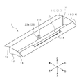
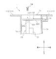
- a step portion 15 is formed in the packaging box 1 (see also FIGS. 7 and 8).
- the step portion 15 is a recess formed in the packaging box 1 by folding the packaging box 1.
- the step portion 15 has a square shape in a side view.
- the front wall 1 a located between the cuts 12 and 12 is the lower surface of the step portion 15, and the bottom wall piece 111 located between the cuts 12 and 12 is the front surface of the step portion 15.
- the arrangement position of the bottom surface of the step portion 15 in the top-to-bottom direction corresponds to the position in the top-and-bottom direction where the end surface of the bottom end 23a of the stand column 23 is disposed.
- the operator lays the stand base 22 horizontally on the step portion 15 and the bottom end portion 23 a of the stand column 23.
- the operator places the long side portion 22 a of the stand base 22 on the lower surface of the step portion 15 and places the long side portion 22 b on the end surface of the bottom side end portion 23 a of the stand column 23.
- the stand base 22 is stably supported by the lower surface of the step portion 15 and the end surface of the bottom side end portion 23 a of the stand column 23.
- the separation distance between the cuts 12, 12, that is, the length in the left-right direction of the step portion 15 corresponds to the length in the longitudinal direction of the long side portion 22 a of the stand base 22. Therefore, when the operator places the long side portion 22a of the stand base 22 on the lower surface of the step portion 15, the stand base 22 is automatically positioned in the left-right direction. As a result, the operator can easily adjust the arrangement position of the insertion hole 221 of the stand base 22 and the arrangement position of the screw hole 231 of the stand column 23 in the front-rear and left-right directions by adjusting the arrangement position of the stand base 22 in the front-rear direction. Can match.
- the stand base 22 may be automatically positioned in the front-rear direction if the long side portion 22a of the stand base 22 is placed on the lower surface of the step portion 15 and abuts against the front surface of the step portion 15.
- a rectangular cut line may be formed in advance on the power bottom wall piece 111. By removing the bottom wall piece 111 of the portion surrounded by the cut line along the cut line, an opening into which the stand base 22 can be inserted (hereinafter referred to as an insertion port) is formed.
- the separation distance between the cuts 12 and 12 is the length of the long side portion 22a. It is provided longer than the length in the longitudinal direction. If it is the above structures, it will arrange
- the operator attaches the stand base 22 to the display device 21 using screws 24 as shown in FIG. That is, the operator assembles the display device 2 inside the packaging box 1. Since the stand base 22 is stably laid horizontally on the step portion 15 and the bottom side end portion 23a of the stand column 23, the operator stands on the stand base 22 without holding the stand base 22 by himself / herself. It can be easily screwed to the bottom end 23a of the column 23. That is, the operator can easily assemble the display device 2.
- the worker places the packing box 1 in the top-to-bottom direction (that is, with the top wall 1e facing upward) with the bottom wall 1f open.
- the display device 21 to which the stand base 22 is attached that is, the display device 2 assembled by the operator is placed in the work place while being accommodated in the packaging box 1.
- the display device 2 immediately after the packaging box 1 is pulled upward is covered with a cushioning material and a cover. Therefore, the worker finally removes the cushioning material and the cover from the display device 2 installed at the work place.
- the packing box 1 is used when the stand base 22 is attached to the display device 21, an object such as a support that supports the stand base 22 is unnecessary. That is, the number of parts does not increase just for assembling the display device 2.
- folds 131 and 132 should just be formed in the suitable location of the packaging box 1.
- the step portion 15 can be easily formed by folding the front wall 1a and the bottom wall piece 111. That is, since the structure of the packaging box 1 is simple, manufacturing cost is reduced. Moreover, since the use of the packaging box 1 is simple, workability is high.
- the display device 21 when the stand base 22 is attached to the display device 21, the display device 21 remains housed in the packaging box 1, and thus the display device 21 can be protected from damage. At this time, since the display device 21 is held in the vertical posture, the display device 2 can be assembled in a work place narrower than the case where the display device 21 is held in the horizontal posture.
- the display device 2 may be configured as a display of a personal computer. In this case, the display device 2 may not include the receiving unit 212 and the signal processing unit 213.
- the shapes of the stand base 22 and the stand column 23 are not limited to the shapes described in the present embodiment.
- the stand base 22 may have an annular shape or a disk shape.
- cut lines 12 and 12 and the fold lines 131 and 132 are not limited to the structure formed in the front wall 1a and the bottom wall piece 111, and may be formed in the rear wall 1b and the bottom wall piece 112. Furthermore, four cuts 12 and 12 and two folds 131 and 132 may be formed in the front wall 1a, the rear wall 1b, and the bottom wall pieces 111 and 112, respectively. In this case, not only the step portion 15 related to the front wall 1 a and the bottom wall piece 111 but also the step portion 15 related to the rear wall 1 b and the bottom wall piece 112 are formed in the packaging box 1.
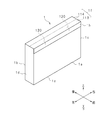
- FIG. FIG. 11 is a perspective view showing an appearance of the packaging box 1 according to Embodiment 2 of the present invention.
- FIG. 12 is a perspective view for explaining an assembly procedure of the electric device according to the second embodiment of the present invention
- FIG. 13 is a partially enlarged longitudinal sectional view of the same. 11 and 13 correspond to FIGS. 1 and 8 of the first embodiment.
- differences between the first and second embodiments will be described, and other parts corresponding to those of the first embodiment are denoted by the same reference numerals and description thereof will be omitted.
- the packaging box 1 of the present embodiment replaces the cut lines 12 and 12, the fold lines 131 and 132, and the bottom wall pieces 111 and 112 of the first embodiment, and the cut lines 120 and 120, the fold lines 133 and 133, and the inner bottom.
- a wall piece 113 and an outer bottom wall piece 114 are provided.
- the packaging box 1 does not include the reinforcing portions 14 and 14 of the first embodiment.
- the packaging box 1 has an assembly fee 1h.
- a rectangular cut line 16 is formed on the front wall 1a between the cuts 120 and 120. In FIG. 12, the cut line 16 is indicated by a broken line. When the front wall 1a is cut out along the cut line 16, an insertion port 17 is formed.
- the cut line 16 and the insertion port 17 will be described.
- the cut line 16 is formed by perforating the cardboard constituting the front wall 1a.
- the cut line 16 has two long side portions 16a and 16b and short side portions 16c and 16c.
- the long side portion 16a is formed on a line connecting ends of the cuts 120, 120 on the front wall 1a side.
- the length of each of the long side portions 16 a and 16 b corresponds to the length of the stand base 22 in the longitudinal direction.
- the length of each short side portion 16 c is longer than the thickness of the stand base 22. Therefore, the stand base 22 can be inserted into the insertion port 17.
- the cuts 120 and 120 have substantially the same configuration as the cuts 12 and 12 of the first embodiment. However, the separation distance between the cut lines 120 and 120 is longer than the length of the long side portion 22a of the stand base 22 in the longitudinal direction.
- the folds 133, 133 are formed on the line connecting the ends of the cuts 120, 120 on the front wall 1 a side and on the left and right sides of the long side part 16 a of the cut line 16.
- Each fold 133 is formed by cutting the inner surface and the center of the corrugated cardboard constituting the front wall 1a in the same manner as the fold 131 of the first embodiment.
- the front wall 1a can be easily folded inward at the formation positions of the fold lines 133 and 133 and the long side portion 16a of the cut line 16. That is, the long side portion 16a functions not only as a cut line but also as a fold line.
- the fold line 134 has substantially the same configuration as the fold line 132 of the first embodiment. However, the fold line 134 is longer than the fold line 132.
- the inner bottom wall piece 113 and the outer bottom wall piece 114 constitute a bottom wall 1f.
- the bottom wall 1f of the present embodiment is partially doubled.
- the inner bottom wall piece 113 has substantially the same configuration as the bottom wall piece 111 of the first embodiment. Therefore, the inner bottom wall piece 113 is formed with a half in the longitudinal direction of each of the cut lines 120 and 120 and a fold line 134.
- the outer bottom wall piece 114 has substantially the same configuration as the bottom wall piece 112 of the first embodiment, but the dimension in the front-rear direction is twice the dimension of the bottom wall piece 112. Further, an assembly allowance 1h is continuously provided at the tip of the outer bottom wall piece 114. The length of the assembly allowance 1h from the distal end portion of the outer bottom wall piece 114 is longer than the length from the proximal end portion of the inner bottom wall piece 113 to the fold line 134 (that is, the half length in the longitudinal direction of the cut 120). .
- the operator When assembling the packaging box 1, the operator folds the distal end portion of the inner bottom wall piece 113 and the proximal end portion and the distal end portion of the outer bottom wall piece 114 respectively toward the outer side of the packaging box 1. .
- the operator places the inner bottom wall piece 113 on the inner side and the outer bottom wall piece 114 on the outer side to bring the inner bottom wall piece 113 and the outer bottom wall piece 114 into contact with each other.
- the bottom opening of the packaging box 1 is closed by the bottom wall 1f (particularly the outer bottom wall piece 114).
- the outer bottom wall piece 114 covers the fold line 134 formed in the inner bottom wall piece 113.
- Such an outer bottom wall piece 114 also has a function as a reinforcing portion that reinforces the fold line 134 from the outside.
- the worker attaches the assembly cost 1h to the outer surface of the front wall 1a using an adhesive or an adhesive tape.
- the assembly allowance 1h covers the fold lines 133, 133 and the cut line 16 formed in the front wall 1a.
- Such an assembling allowance 1h also has a function as a reinforcing portion for reinforcing the folds 133, 133 and the cut line 16 from the outside.
- the packaging box 1 may be provided with the tape-shaped reinforcement part affixed from the outer side on the formation position of the fold 133,133.
- the reinforcing portion may be attached to the cut line 16 as well. However, in this case, it is desirable to provide a cut line in the reinforcing portion corresponding to the cut line 16.
- An engagement groove (not shown) is formed in each of the bottom end 23 a of the stand column 23 and the stand base 22.
- the stand base 22 is engaged with the stand column 23 by inserting the engagement groove on the stand base 22 side into the engagement groove on the bottom end 23 a side from the front side.
- the worker places the packaging box 1 on the work place with the top and bottom reversed (that is, with the bottom wall 1f facing upward).
- the operator removes the assembly allowance 1h from the front wall 1a.
- the worker folds the base end portions of the inner bottom wall piece 113 and the outer bottom wall piece 114 outward to open the bottom wall 1f like a hinge lid. After opening the bottom wall 1f, the operator arranges the inner bottom wall piece 113 so as to be orthogonal to the front wall 1a.
- the operator takes out the stand base 22 and the screw 24 through the bottom opening of the packaging box 1. Further, the operator folds the base end portion of the inner bottom wall piece 113 positioned between the cut lines 120 and 120 into the inner side of the packaging box 1, and folds 133 and 133 and the long side portion 16 a of the cut line 16 and the fold line. 134 are folded inward on the inside of the packing box 1. As a result, a step portion 18 similar to the step portion 15 of the first embodiment is formed in the packaging box 1. At this time, the cut line 16 functions as a fold. Next, the operator pulls out the front wall 1 a inside the cut line 16 along the cut line 16. As a result, the insertion port 17 is formed. Even if the step portion 18 is formed after the insertion port 17 is formed, there is no particular problem.
- the step portion 18 has a square step shape when viewed from the side.
- the front wall 1 a located between the cuts 120 and 120 is the lower surface of the step portion 18, and the bottom wall piece 111 located between the cuts 120 and 120 is the front surface of the step portion 18.
- the insertion port 17 is open to the front surface of the step portion 18, and the formation position of the long side portion corresponding to the long side portion 16 a of the insertion port 17 in the vertical direction is the arrangement position of the lower surface of the step portion 18 in the vertical direction. equal.
- the operator inserts the stand base 22 into the insertion port 17 from the outside of the packing box 1 as shown in FIG. Thereafter, the operator slides the stand base 22 along the lower surface of the step portion 18. As a result, the engagement groove on the stand base 22 side is inserted into the engagement groove on the bottom end 23a side from the front side.
- the stand base 22 engaged with the stand column 23 is stably placed on the bottom end 23 a and the step unit 18 of the stand column 23.
- the operator attaches the stand base 22 to the display device 21 using the screws 24.
- the worker places the packaging box 1 in the top-to-bottom direction (that is, with the top wall 1e facing upward) with the bottom wall 1f open.
- the operator pulls the packaging box 1 upward to expose the display device 2. Even if the packaging box 1 as described above is used, the display device 2 can be easily assembled as in the first embodiment.
- FIG. 14 is a perspective view showing an appearance of the packaging box 3 according to the third embodiment of the present invention, and corresponds to FIG. 1 of the first embodiment.
- the packaging box 3 has a rectangular parallelepiped appearance.
- the packaging box 3 has a structure that can be divided into two parts: a top box 30 having an opening at the bottom and a bottom box 31 having an opening at the top.
- the length of the top box 30 in the top-and-bottom direction (that is, the height) is higher than the height of the bottom box 31.
- the top box 30 has a rectangular top wall 30a, top back wall 30b, top right wall 30c, top left wall 30d, and top wall 3e.
- the bottom box 31 includes a rectangular bottom front wall 31a, a bottom rear wall 31b, a bottom right wall 31c, a bottom left wall 31d, and a bottom wall 3f.
- the bottom end of the top box 30 is accommodated in the bottom box 31.
- the outer surface of the portion accommodated in the bottom box 31 of each of the top side front wall 30a, top side rear wall 30b, top side right wall 30c, and top side left wall 30d is the bottom side front wall 31a, bottom
- the side rear wall 31b, the bottom right wall 31c, and the bottom left wall 31d are in contact with the inner surfaces.
- the bottom side end surface of the top box 30 is in contact with the inner surface of the bottom wall 3f. Accordingly, the bottom opening of the top box 30 is closed by the bottom box 31 (particularly the bottom wall 3 f), and the top opening of the bottom box 31 is closed by the top box 30.
- the display device 21, the stand base 22, and the screw 24 are accommodated as separate bodies (see FIG. 2 of the first embodiment).
- the display device 21, the stand base 22, and the screw 24 accommodated in the packaging box 3 are wrapped in a cover or a sachet (not shown) and are held by a cushioning material (not shown).
- the display device 21 accommodated in the packaging box 3 has a front surface (and a rear surface) facing the top side front wall 30a (and top side rear wall 30b) of the packaging box 3, and a top side (and bottom side) of the packaging box 3.
- the top wall 3e (and the bottom wall 3f) of 3 is arranged in a vertical posture. Accordingly, the bottom end 23a of the stand column 23 is disposed on the bottom wall 3f side.
- the stand base 22 accommodated in the packing box 3 is arranged in a vertical posture between the back surface of the display device 21 and the top side rear wall 30b.
- the screws 24 accommodated in the packaging box 3 are arranged in appropriate gaps inside the packaging box 3 while being accommodated in a small bag (not shown).
- the present embodiment uses the packaging box 3 as will be described later.
- FIG. 15 is a development view of the inner surface side of the packing box 3 and corresponds to FIG. 3 of the first embodiment.
- FIG. 15 is also a diagram showing box-making sheets 300 and 301 for forming the packing box 3.
- FIG. 15 shows the side that should be the inner surface side of the packaging box 3 in the box-making sheets 300 and 301.
- FIGS. 16 to 19 are diagrams for explaining the assembly procedure of the electric device
- FIGS. 16 and 17 are perspective views (corresponding to FIGS. 5 and 6 of the first embodiment)
- FIG. 19 corresponds to FIG. 7 of the first embodiment
- FIG. 19 is a partially enlarged vertical sectional view of the upper portion of the packing box 3 (corresponding to FIG. 8 of the first embodiment).
- FIG. 14 represents the placement of the packing box 3 upside down
- FIG. 16 represents the removal of the bottom box 31 and the removal of the stand base 22
- FIG. FIG. 18 shows the horizontal mounting of the stand base 22
- FIG. 19 shows the horizontal mounting and mounting of the stand base 22.
- the top box body 30 and the bottom box body 31 of the packaging box 3 are assembled by folding the box making sheets 300 and 301 cut out into a shape as shown in FIG.
- Each of the box making sheets 300 and 301 is made of one cardboard.
- the box-making sheet 300 includes a portion to be the top front wall 30a, a portion to be the top rear wall 30b, a portion to be the top right wall 30c, a portion to be the top left wall 30d, and a top wall. It has a portion to be 3e and a rectangular assembly allowance 30g.
- the box making sheet 301 includes a portion to be the bottom front wall 31a, a portion to be the bottom rear wall 31b, a portion to be the bottom right wall 31c, a portion to be the bottom left wall 31d, and a bottom wall. It has a part to be 3f and a rectangular assembly allowance 31g.
- the portion to be the top front wall 30a, the portion to be the bottom front wall 31a, the portion to be the top wall 3e, and the portion to be the bottom wall 3f are also referred to as the top front wall 30a. ..., the bottom front wall 31a, ..., the top wall 3e, and the bottom wall 3f.
- the top wall 3e has top wall pieces 301 and 302 similar to the top wall pieces 101 and 102 of the first embodiment.
- the bottom wall 3f has bottom wall pieces 311 and 312 similar to the bottom wall pieces 111 and 112 of the first embodiment. However, unlike the bottom wall piece 111, the bottom wall piece 311 is not formed to correspond to the cut lines 12, 12 and the fold line 132.
- the top side right wall 30c, the top side left wall 30d, and one top wall piece 301 are continuously provided on the top front wall 30a.
- An assembly allowance 30g, a top right wall 30c, and the other top wall piece 302 are continuously provided on the top rear wall 30b.
- Three locking holes 30i, 30i,... are formed at the bottom end of each of the top front wall 30a and the top rear wall 30b.
- the locking holes 30i, 30i,... are arranged side by side in the left-right direction (the direction along the base ends of the top wall pieces 301, 302).
- a locking hole 30i at the center in the left-right direction in the top side front wall 30a is formed in a range surrounded by cuts 32, 32 and folds 33, which will be described later, so as not to interfere with any of the cuts 32, 32 and folds 33.
- a bottom right wall 31c, a bottom left wall 31d, and one bottom wall piece 311 are continuously provided on the bottom front wall 31a.
- An assembly allowance 31g, a bottom right wall 31c, and the other bottom wall piece 312 are continuously provided on the bottom rear wall 31b.
- Three locking holes 31i, 31i,... are provided at the bottom end portions of the bottom front wall 31a and the bottom rear wall 31b, respectively.
- the locking holes 31i, 31i,... Of the bottom front wall 31a (and the bottom rear wall 31b) correspond to the locking holes 30i, 30i,... Of the top front wall 30a (and the top rear wall 30b). It is arranged in.
- the length of the bottom front wall 31a in the top-to-bottom direction is longer than the length of the cut 32 described below, and the length of the top front wall 30a in the top-to-bottom direction is the length of the bottom front wall 31a in the top-to-bottom direction. Longer than that.
- the packing box 3 is formed with cuts 32 and 32 and a fold 33.
- the cut lines 32 and 32 are indicated by bold lines, and the fold line 33 is indicated by a one-dot chain line. Further, in FIG. 15, a portion to be mountain-folded toward the outer side of the top box 30 and the bottom box 31 when the top box 30 and the bottom box 31 are assembled is indicated by a broken line. Yes.
- Each cut 32 is formed from the bottom end of the top front wall 30a to the middle in the top and bottom direction.
- the top-to-bottom direction formation position of the cut 32 is the top-to-bottom position where the end face of the bottom end 23a of the stand column 23 is arranged when the display device 21 is accommodated in the top box 30. It corresponds to.
- the cut 32 is formed by cutting through the cardboard constituting the top front wall 30a.
- the cuts 32, 32 are parallel to each other, and the longitudinal direction of each cut 32 is a direction orthogonal to the base end portion of the top wall piece 301.
- the separation distance between the cuts 32 and 32 is the length of the long side portion 22a (that is, the top wall of the stand base 22 when the stand base 22 is attached to the display device 21 accommodated in the top box 30). Corresponds to the dimension along the base end of the piece 301.
- the center position in the separation direction between the cuts 32 and 32 corresponds to the position in the left-right direction where the end surface of the bottom end 23a of the stand column 23 is arranged when the display device 21 is accommodated in the top box 30. is doing.
- the crease 33 is formed by connecting the top ends of the cut lines 32 and 32. That is, the fold line 33 is formed in the top side front wall 30 a located between the cut lines 32, 32 in parallel with the base end portion of the top wall piece 301. Further, the formation position of the fold 33 in the top-to-bottom direction corresponds to the top-to-bottom position where the end surface of the bottom side end 23a of the stand column 23 is arranged when the display device 21 is accommodated in the top box 30. ing.
- the fold line 33 is formed by cutting the inner surface and the center of the corrugated cardboard constituting the top side front wall 30a.
- the formation position of the fold line 33 on the top side front wall 30a is lower in strength than other portions. For this reason, the top front wall 30a is naturally folded inward at the formation position of the fold 33 unless the bending at the formation position of the fold 33 is hindered.
- the top front wall 30a may be configured so that it can be easily folded inward at the position where the fold line 33 is formed when the operator applies an appropriate external force.
- the operator assembles the top box 30 using the box-making sheet 300.
- the worker folds the boundary portion between the top front wall 30a and the top right wall 30c, the top left wall 30d, and the top wall piece 301 toward the outside of the top box 30.
- the worker folds the boundary portion between the top side rear wall 30 b and the assembly allowance 30 g, the top side right wall 30 c, and the top wall piece 302 to the outside of the top box 30.
- the operator attaches the assembly allowance 30g to the inner surface of the top left wall 30d.
- the operator abuts the tip portions of the top wall pieces 301 and 302 and affixes an adhesive tape (not shown) across the top wall pieces 301 and 302 to the outer surface of the top wall pieces 301 and 302. As a result, the top wall 3e is formed. As described above, the top box 30 having the bottom opening is assembled.
- the operator assembles the bottom box 31 using the box-making sheet 301.
- the worker folds the boundary portions of the bottom front wall 31a, the bottom right wall 31c, the bottom left wall 31d, and the bottom wall piece 311 to the outside of the bottom box 31.
- the worker folds the boundary portion between the bottom side rear wall 31 b and the assembly allowance 31 g, the bottom right wall 31 c, and the bottom wall piece 312 to the outside of the bottom box 31.
- the operator attaches the assembly allowance 31g to the inner surface of the bottom left wall 31d.
- the operator abuts the leading end portions of the bottom wall pieces 311 and 312 and attaches an adhesive tape (not shown) across the bottom wall pieces 311 and 312 to the outer surface of the bottom wall pieces 311 and 312.
- an adhesive tape (not shown) across the bottom wall pieces 311 and 312 to the outer surface of the bottom wall pieces 311 and 312.
- the operator places the bottom box 31 with the bottom wall 3f formed facing downward.
- the worker arranges the display device 21 and the stand base 22 each covered with a cover and the screw 24 accommodated in the small bag inside the bottom box 31. Further, the worker appropriately arranges cushioning materials around the display device 21 and the stand base 22. It is desirable that the stand base 22 and the screw 24 are arranged in the vicinity of the bottom wall 3f so that they can be easily taken out from the top box 30 through the bottom opening of the top box 30 as will be described later.
- the operator covers the top box 31 on the display device 21 and the stand base 22. Furthermore, the operator inserts the bottom end of the top box 30 between the inner surface of the bottom box 31 and the display device 21 and the stand base 22 accommodated in the bottom box 31. Then, the locking holes 30i, 30i,... And the locking holes 31i, 31i,. Next, the operator repeats six times that the locking member (not shown) is inserted and locked into the corresponding locking holes 30i and 31i. As a result, since the top side front wall 30a and the bottom side front wall 31a are connected, and the top side rear wall 30b and the bottom side rear wall 31b are connected, the top side box body 30 and the bottom side box body 31 are connected. Integrate.
- the cuts 32 and 32 and the fold 33 are covered with the bottom front wall 31 a of the bottom box 31 from the outside of the top box 30.
- the cut lines 32 and 32 and the fold line 33 are protected from deformation or damage. Further, the fold line 33 is prevented from being bent unnecessarily.
- the procedure for assembling the display device 2 will be described with reference to FIGS. 14 and 16 to 19.
- the worker places the packing box 3 on the work place with the top and bottom reversed (that is, with the bottom wall 3f facing upward).
- the display device 21 is held in a vertical posture in which the top and bottom are reversed.
- the operator prepares a tool for removing or destroying the screw corresponding to the screw 24 and the locking member locking the locking holes 30i, 31i.
- FIG. 16 shows a state in which the fold line 33 has not been bent yet.
- the fold line 33 is naturally folded inward as shown in FIG.
- a step 35 is formed in the top box 30 (see also FIGS. 18 and 19).
- the step portion 35 has a flat plate shape protruding forward of the top box 30.
- the top front wall 30 a located between the cuts 32, 32 is the lower surface of the step portion 35.
- the arrangement position of the lower surface of the step portion 35 in the top-to-bottom direction corresponds to the position in the top-and-bottom direction where the end surface of the bottom end 23a of the stand column 23 is disposed.
- the operator takes out the stand base 22 covered with the cover and the screw 24 accommodated in the small bag through the bottom opening of the top box 30.
- the operator also takes out the cushioning material that obstructs the removal of the stand base 22 and the screw 24 from the top box 30.
- the cushioning material necessary for holding the display device 21 in the vertical posture is left inside the top box 30.
- various operations on the display device 21 are performed in a state where the display device 21 is accommodated in the top box 30 until the top box 30 is extracted.
- the operator removes the cover from the stand base 22 and takes out the screw 24 from the pouch.
- the worker removes or beats at least a portion of the cover of the display device 21 that covers the bottom-side end portion 23 a of the stand column 23. As a result, the end surface of the bottom end 23a of the stand column 23 and the screw hole 231 appear.
- the operator lays the stand base 22 horizontally on the step portion 35 and the bottom end portion 23 a of the stand column 23.
- the operator places the long side portion 22 a of the stand base 22 on the lower surface of the step portion 35 and places the long side portion 22 b on the end surface of the bottom side end portion 23 a of the stand column 23.
- the stand base 22 is stably supported by the lower surface of the step portion 35 and the end surface of the bottom side end portion 23 a of the stand column 23.
- the separation distance between the cut lines 32 corresponds to the length in the longitudinal direction of the long side portion 22 a of the stand base 22. Therefore, when the operator places the long side portion 22a of the stand base 22 on the lower surface of the step portion 35, the stand base 22 is automatically positioned in the left-right direction. As a result, the operator can easily adjust the arrangement position of the insertion hole 221 of the stand base 22 and the arrangement position of the screw hole 231 of the stand column 23 in the front-rear and left-right directions by adjusting the arrangement position of the stand base 22 in the front-rear direction. Can match.
- the operator attaches the stand base 22 to the display device 21 using screws 24 as shown in FIG. That is, the operator assembles the display device 2 inside the top box 30. Since the stand base 22 is stably laid horizontally on the step portion 35 and the bottom end portion 23a of the stand column 23, the operator stands on the stand base 22 without holding the stand base 22 by himself / herself. It can be easily screwed to the bottom end 23a of the column 23. That is, the operator can easily assemble the display device 2.
- the worker places the top box 30 in the top-to-bottom direction (that is, with the top wall 3e facing upward) (see FIG. 9 of Embodiment 1).
- the display device 21 to which the stand base 22 is attached that is, the display device 2 assembled by the operator is placed in the work place in a state of being accommodated in the top box 30.
- the display device 2 immediately after the packaging box 3 is extracted upward is covered with a cushioning material and a cover. Therefore, the worker finally removes the cushioning material and the cover from the display device 2 installed at the work place.
- the packing box 3 is provided with a cut line for forming the insertion port described in the first embodiment or a cut line 16 for forming the insertion port 17 of the second embodiment. There is no need to be.
- the packing box 3 is used when the stand base 22 is attached to the display device 21, an object such as a support that supports the stand base 22 is unnecessary. That is, the number of parts does not increase just for assembling the display device 2.
- fold 33 should just be formed in the appropriate location of the top box 30.
- the step portion 35 is naturally formed when the bottom box 31 is removed, the work procedure is simple. That is, since the structure of the packaging box 3 is simple, manufacturing cost is reduced. Moreover, since the use of the packing box 3 is simple, workability is high.
- the display device 21 remains housed in the top box 30, so that the display device 21 can be protected from damage.
- the display device 21 since the display device 21 is held in the vertical posture, the display device 2 can be assembled in a work place narrower than the case where the display device 21 is held in the horizontal posture.
- the packing box 3 has a more complicated structure than the packing box 1 of the first embodiment because it is configured to be split into two.
- fold 33 are not limited to the structure formed in the top side front wall 30a, The structure formed in the top side rear wall 30b may be sufficient. Moreover, the cut
- two cut lines may be formed instead of the cut lines 32 and 32.
- the display device 2 is assembled in the same procedure as that in the case where the cut lines 32 and 32 are formed from the beginning except that the procedure for forming the cut lines 32 and 32 using two cut lines is increased. Can do. With such a configuration, for example, the step 35 is unnecessarily formed when the packaging box 3 is assembled, and the inconvenience that the assembling work of the packaging box 3 is hindered is suppressed.
- the cut lines 32, 32 may be formed at the boundary portions between the top side front wall 30a, the top side right wall 30c, and the top side left wall 30d instead of the top side front wall 30a.
- a cut line may be formed instead of the fold line 33.
- the operator forms a rectangular recess in the top front wall 30a using the cut lines 32, 32 and the cut line, and the upper end surface in the formed recess and the bottom end 23a of the stand column 23
- the stand base 22 is placed on the surface.
- such a recess may be formed in the top box 30 in advance. Before the assembly work of the display device 2 is started, there is no problem because the bottom box 31 covers the recess.
- FIG. 20 is a perspective view showing an appearance of the packaging box 4 according to the fourth embodiment of the present invention, and corresponds to FIG. 1 of the first embodiment.
- the packaging box 4 has a rectangular parallelepiped appearance.
- the packaging box 4 has a rectangular front wall 4a, rear wall 4b, right wall 4c, left wall 4d, top wall 4e, and bottom wall 4f.
- the rear wall 4b, the right wall 4c, the left wall 4d, and the ceiling wall 4e correspond to the rear wall 1b, the right wall 1c, the left wall 1d, and the ceiling wall 1e of the first embodiment.
- the display device 21, the stand base 22, and the screw 24 are accommodated as separate bodies (see FIG. 2 of the first embodiment).
- the display device 21, the stand base 22, and the screw 24 accommodated in the packaging box 4 are wrapped in a cover or a sachet (not shown) and held by a cushioning material (not shown).
- the front (and the back) faces the front wall 4a (and the rear wall 4b) of the packaging box 4, and the top side (and the bottom side) is the ceiling wall of the packaging box 4.
- 4e (and bottom wall 4f) is arranged in a vertical posture so as to face. Therefore, the bottom end 23a of the stand column 23 is disposed on the bottom wall 4f side.
- the stand base 22 accommodated in the packaging box 4 is arranged in a vertical posture between the back surface of the display device 21 and the rear wall 4b.
- the screws 24 accommodated in the packaging box 4 are arranged in appropriate gaps inside the packaging box 4 while being accommodated in a small bag (not shown).
- the present embodiment uses the packaging box 4 as will be described later.
- FIG. 21 is a development view of the inner surface side of the packaging box 4 and corresponds to FIG. 3 of the first embodiment.
- FIG. 21 is also a diagram showing a box-making sheet 400 for forming the packing box 4.
- FIG. 21 shows the side that should be the inner surface side of the packaging box 4 in the box-making sheet 400.
- FIG. 22 to 24 are diagrams for explaining an assembly procedure of the electric device
- FIG. 22 and FIG. 23 are perspective views (corresponding to FIG. 5 or FIG. 6 of the first embodiment)
- FIG. FIG. 9 is a partially enlarged vertical sectional view (corresponding to FIG. 8 of the first embodiment) in which the upper part of FIG. 20 represents the placement of the packing box 4 upside down
- FIG. 22 represents the process of opening the bottom wall 4f
- FIG. 23 represents the opening of the bottom wall 4f
- the removal of the stand base 22 and 24 shows the formation of the stepped portion 45
- FIG. 24 shows the horizontal mounting and attachment of the stand base 22.
- the packaging box 4 is assembled by folding a box making sheet 400 cut into a shape as shown in FIG.
- the box-making sheet 400 is made of a single cardboard.
- the box-making sheet 400 includes a portion to be the front wall 4a, a portion to be the rear wall 4b,..., A portion to be the bottom wall 4f, and the rectangular assembly allowances 4g and 4h, and insertion described later. It has the part which should become piece 4j and 4j.
- the part to be the front wall 4a, the part to be the rear wall 4b,..., And the part to be the bottom wall 4f are also referred to as the front wall 4a, the rear wall 4b,.
- the assembly cost 4g corresponds to the assembly cost 1g of the first embodiment.
- the assembly cost 4h corresponds to the assembly cost 1g of the second embodiment.
- the top wall 4e has top wall pieces 401 and 402 similar to the top wall pieces 101 and 102 of the first embodiment.
- the bottom wall 4f is partially double or triple.
- the bottom wall 4f includes inner bottom wall pieces 411 and outer bottom wall pieces 412 similar to the inner bottom wall pieces 113 and outer bottom wall pieces 114 of the second embodiment, and inner bottom wall pieces 413 and 414.
- unlike the inner bottom wall piece 113 of the second embodiment neither the cut nor the crease is formed in the inner bottom wall piece 411.
- a right wall 4c, a left wall 4d, one top wall piece 401, and an inner bottom wall piece 411 are continuously provided on the front wall 4a.
- An assembly allowance 4g, a right wall 4c, the other top wall piece 402, and an outer bottom wall piece 412 are continuously provided on the rear wall 4b.
- An inner bottom wall piece 413 is continuously provided on the right wall 4c.
- An inner bottom wall piece 414 is continuously provided on the left wall 4d.
- An assembly allowance 4h is continuously provided at the tip of the outer bottom wall piece 412. The length from the front end portion of the outer bottom wall piece 412 of the assembly allowance 4h is equal to the length of the cut 42 described below.
- Fan-shaped insertion pieces 4j, 4j are continuously provided at both left and right ends of the assembly allowance 4h.
- the packaging box 4 is formed with cuts 42 and 42 and a fold 43.
- the cut lines 42 and 42 are indicated by bold lines, and the fold line 43 is indicated by a one-dot chain line.
- FIG. 21 the part which should be mountain-folded in the direction which becomes the outer side of the packaging box 4 at the time of the assembly of the packaging box 4 is shown with the broken line.
- the cuts 42 and 42 are parallel to each other. Each cut 42 is formed at the boundary between the front wall 4a, the right wall 4c, and the left wall 4d from the bottom end of the front wall 4a to the middle in the vertical direction. The formation position of the top end of the cut 42 in the top-to-bottom direction corresponds to the top-to-bottom position where the end surface of the bottom end 23 a of the stand column 23 is arranged when the display device 21 is accommodated in the packaging box 4. ing.
- the cut line 42 is formed by cutting through a cardboard that forms a boundary portion between the front wall 4a and the right wall 4c (or the left wall 4d).
- the crease 43 is formed by connecting the top ends of the cut lines 42 and 42. That is, the fold line 43 is formed on the front wall 4 a located between the cut lines 42 and 42, and is parallel to the base end portion of the inner bottom wall piece 411.
- the formation position of the fold 43 in the top-to-bottom direction corresponds to the top-to-bottom position where the end surface of the bottom side end portion 23 a of the stand column 23 is arranged when the display device 21 is accommodated in the packaging box 4.
- the crease 43 is formed by making a cut in the inner surface and the inner core of the corrugated board constituting the front wall 4a. For this reason, the front wall 4 a and the inner bottom wall piece 411 can be easily folded inward at the formation position of the fold 43.
- a tape-shaped reinforcing portion such as the reinforcing portion 14 of the first embodiment may be attached to the formation position of the fold 43 from the outside.
- the assembly allowance 4h may cover the crease 43 as in the assembly allowance 1h of the second embodiment.
- the front wall 4a may be configured to be naturally folded inwardly as long as the bending at the position where the crease 43 is formed is not hindered.
- the operator When assembling the packaging box 4 and accommodating the display device 21, the stand base 22, and the screws 24, first, the operator prepares a box-making sheet 400. Next, the worker folds the boundary portion between the front wall 4 a, the right wall 4 c, the left wall 4 d, the top wall piece 401, and the inner bottom wall piece 411 toward the outside of the packaging box 4. Further, the worker folds the boundary portion between the rear wall 4b and the assembly cost 4g, the right wall 4c, the top wall piece 402, and the outer bottom wall piece 412 toward the outside of the packaging box 4. Further, the worker folds the boundary portion between the right wall 4 c and the inner bottom wall piece 413 and the boundary portion between the left wall 4 d and the inner bottom wall piece 414 toward the outside of the packaging box 4.
- the worker folds the boundary portion between the outer bottom wall piece 412 and the assembly allowance 4 h toward the outside of the packaging box 4.
- the worker folds the boundary portion between the assembly allowance 4 h and the insertion pieces 4 j and 4 j into the outer side of the packaging box 4.
- the operator attaches the assembly allowance 4g to the inner surface of the left wall 4d using an adhesive or staples.
- the worker places the inner bottom wall piece 411 on the inside, places the inner bottom wall pieces 413 and 414 on the outside of the inner bottom wall piece 411, and places the outer bottom wall piece 412 on the inner bottom wall pieces 411 and 413. , 414, the inner bottom wall pieces 411, 413, 414 and the outer bottom wall piece 412 are brought into contact with each other.
- the bottom opening of the packaging box 4 is closed by the bottom wall 4f (particularly the outer bottom wall piece 412).
- the operator inserts the insertion pieces 4j and 4j into the cut lines 42 and 42, and further attaches the assembly allowance 4h to the outer surface of the front wall 4a using an adhesive or an adhesive tape.
- the bottom wall 4f can be opened by removing the assembly allowance 4h from the front wall 4a and extracting the insertion pieces 4j, 4j from the cuts 42, 42.
- the bottom wall 4f is like a hinge lid by folding the base end portions of the inner bottom wall pieces 413, 414 and the outer bottom wall piece 412 inwardly and further folding the crease 43 inwardly. Released.
- an opening is formed at the bottom of the packaging box 4. Further, a step portion 45 to be described later is formed.
- the operator places the packaging box 4 with the formed bottom wall 4f facing downward.
- the operator appropriately disposes cushioning materials inside the packaging box 4, and connects the display device 21 and the stand base 22 covered with the cover and the screws 24 accommodated in the sachets to the inside of the packaging box 4.
- the stand base 22 and the screw 24 are arranged in the vicinity of the bottom wall 4f so that they can be easily taken out from the packing box 4 through the bottom opening of the packing box 4 as described later.
- the operator makes contact with the top ends of the top wall pieces 401, 402, and attaches the top wall pieces 401, 402 to the outer surface of the top wall pieces 401, 402.
- An adhesive tape (not shown) is pasted. As a result, the top wall 4e is formed.
- FIG. 20 the worker places the packaging box 4 on the work place with the top and bottom reversed (that is, with the bottom wall 4f facing upward). At this time, inside the packaging box 4, the display device 21 is held in a vertical posture that is upside down.
- the operator removes the assembly allowance 4h from the front wall 4a and takes out the insert pieces 4j and 4j from the cuts 42 and 42.
- the worker folds the base ends of the inner bottom wall pieces 413, 414 and the outer bottom wall piece 412 inwardly.
- the operator folds the crease 43 inwardly.
- the bottom wall 4f is opened and a step 45 is formed (see also FIG. 24).
- the step 45 has a plate shape protruding forward of the packaging box 4.
- the front wall 4 a located between the cuts 42 and 42 is the lower surface of the stepped portion 45.
- the arrangement position in the top and bottom direction of the lower surface of the stepped portion 45 corresponds to the position in the top and bottom direction where the end face of the bottom side end 23a of the stand column 23 is arranged.
- the inner bottom wall piece 411 is the front surface of the stepped portion 45.
- the stepped portion 45 has a flat plate shape having a lower surface and no front surface. That is, the front surface that the step portion 15 of the first embodiment or the step portion 18 of the second embodiment has does not exist in the step portion 35 (see FIGS. 8, 13, and 24).
- the packaging box 4 is provided with a cut line for forming the insertion port described in the first embodiment or a cut line 16 for forming the insertion port 17 of the second embodiment. There is no need to be.
- the operator takes out the stand base 22 covered with the cover and the screw 24 accommodated in the small bag through the bottom opening of the packaging box 4.
- the operator also takes out the cushioning material that obstructs the removal of the stand base 22 and the screw 24 from the packaging box 4.
- the cushioning material necessary for holding the display device 21 in the vertical posture is left inside the packaging box 4.
- various operations on the display device 21 are performed in a state where the display device 21 is accommodated in the packaging box 4 until the packaging box 4 is extracted as described later.
- the operator removes the cover from the stand base 22 and takes out the screw 24 from the pouch.
- the worker removes or beats at least a portion of the cover of the display device 21 that covers the bottom-side end portion 23 a of the stand column 23. As a result, the end surface of the bottom end 23a of the stand column 23 and the screw hole 231 appear.
- the worker lays the stand base 22 horizontally on the stepped portion 45 and the bottom side end portion 23 a of the stand column 23.
- the operator places the long side portion 22 a of the stand base 22 on the lower surface of the stepped portion 45 and places the long side portion 22 b on the end surface of the bottom side end portion 23 a of the stand column 23.
- the stand base 22 is stably supported by the lower surface of the stepped portion 45 and the end surface of the bottom side end portion 23 a of the stand column 23.
- the operator attaches the stand base 22 to the display device 21 using screws 24 as shown in FIG. That is, the operator assembles the display device 2 inside the packaging box 4. Since the stand base 22 is stably placed horizontally on the step portion 45 and the bottom side end portion 23a of the stand column 23, the operator stands on the stand base 22 without holding the stand base 22 by himself / herself. It can be easily screwed to the bottom end 23a of the column 23. That is, the operator can easily assemble the display device 2.
- the worker places the packing box 4 in the top-to-bottom direction (that is, with the top wall 4e facing upward) with the bottom wall 4f open (see FIG. 9 of Embodiment 1). reference).
- the display device 21 to which the stand base 22 is attached that is, the display device 2 assembled by the operator is placed in the work place while being accommodated in the packaging box 4.
- the display device 2 immediately after the packaging box 4 is pulled upward is covered with a cushioning material and a cover. Therefore, the worker finally removes the cushioning material and the cover from the display device 2 installed at the work place.
- the packing box 4 is used when the stand base 22 is attached to the display device 21, an object such as a support for supporting the stand base 22 is unnecessary. That is, the number of parts does not increase just for assembling the display device 2.
- fold 43 should just be formed in the appropriate location of the packaging box 4.
- FIG. 45 can be easily formed. That is, since the structure of the packaging box 4 is simple, manufacturing cost is reduced. Moreover, since the use of the packaging box 4 is simple, workability is high.
- the display device 21 is still accommodated in the packaging box 4, so that the display device 21 can be protected from damage.
- the display device 21 since the display device 21 is held in the vertical posture, the display device 2 can be assembled in a work place narrower than the case where the display device 21 is held in the horizontal posture.
- the cuts 42, 42 are formed at the boundary between the top side front wall 30a, the top side right wall 30c, and the top side left wall 30d, the length in the left-right direction of the step 45 is the packaging box. 4 equal to the length in the left-right direction. Therefore, the display device 2 can be assembled using the common packaging box 4 regardless of the size and shape of the stand base 22.
- the cut lines 42 and 42 and the fold line 43 are not limited to the boundary portion between the front wall 4a and the right wall 4c and the left wall 4d, and the structure formed in the front wall 4a, but the rear wall 4b and the right wall. 4c and the left wall 4d may be configured to be formed on the boundary between the left wall 4d and the rear wall 4b. Moreover, the structure by which both the cut
- two cut lines may be formed instead of the cut lines 42 and 42.
- the display device 2 is assembled in the same procedure as the case where the cuts 42 and 42 are formed from the beginning, except that the procedure for forming the cuts 42 and 42 using two cut lines is increased. Can do. With such a configuration, for example, the step 45 is unnecessarily formed when the packaging box 4 is assembled, and the inconvenience that the assembling work of the packaging box 4 is hindered is suppressed.
- a cut line may be formed instead of the crease 43.
- the operator uses the cut lines 42 and 42 and the cut line to reduce the length of the front wall 4a in the vertical direction, and shortens the shortened upper end surface of the front wall 4a and the bottom end portion 23a of the stand column 23.
- the stand base 22 is placed on the top.
- at least one of the cuts 42, 42 may be formed in the front wall 4a.
- a cut that divides the inner bottom wall piece 411 is formed in the inner bottom wall piece 411 on the extension line of the cut 42.
- the operator When the distance between the cuts 42, 42, that is, the length in the left-right direction of the step 45, corresponds to the length in the longitudinal direction of the long side portion 22a of the stand base 22, the operator If the portion 22a is placed on the lower surface of the step portion 45, the stand base 22 is automatically positioned in the left-right direction. As a result, the operator can easily adjust the arrangement position of the insertion hole 221 of the stand base 22 and the arrangement position of the screw hole 231 of the stand column 23 in the front-rear and left-right directions by adjusting the arrangement position of the stand base 22 in the front-rear direction. Can match.
- the stand base 22 may be automatically positioned in the front-rear direction.
- FIG. FIG. 25 is a perspective view showing an appearance of the packaging box 1 according to the fifth embodiment of the present invention.
- FIG. 25 corresponds to FIG. 1 of the first embodiment.
- 26 and 27 are development views of the inner surface side and the outer surface side of the packaging box 1.
- 28 to 31 are diagrams for explaining an assembly procedure of the electric device. 26 to 31 correspond to FIGS. 3 to 8 of the first embodiment.
- differences between the first and fifth embodiments will be described, and other parts corresponding to those of the first embodiment are denoted by the same reference numerals, and description thereof will be omitted.
- the display device 2 according to the present embodiment has substantially the same configuration as the display device 2 according to the first embodiment (see FIGS. 2, 5 to 8, and 10).
- the stand base 22 of the present embodiment has a longer front and back length than the stand base 22 of the first embodiment. Specifically, the length before and after the long side portion 22b is long.
- the packaging box 1 is assembled by folding a box-making sheet 100 cut into a shape as shown in FIGS. 26 and 27.
- the packaging box 1 is formed with two cuts 12, 12 and cuts 121, 121, and two folds 135, 135 and folds 136, 136, respectively.
- Each cut 12, 121 is indicated by a bold line.
- Each fold 135, 136 is indicated by a one-dot chain line.
- FIG.26 and FIG.27 the part which should be mountain-folded in the direction which becomes the outer side of the packaging box 1 at the time of the assembly of the packaging box 1 is shown with the broken line.
- Each cut 121 is formed over the rear wall (side wall) 1b and the bottom wall piece 112.
- the cut 121 is formed by making a cut through the cardboard constituting the rear wall 1b and the bottom wall piece 112.
- the longitudinal direction of the cut 121 is orthogonal to the base end portion of the bottom wall piece 112. That is, the cuts 121 and 121 are parallel to each other.
- the length from the end on the rear wall 1b side of the cut 121 to the base end of the bottom wall piece 112 is equal to the length from the end on the bottom wall 1f side of the cut 121 to the base end of the bottom wall piece 112.
- the vertical position of the end on the rear wall 1b side of the cut 121 is the vertical position where the end surface of the bottom end 23a of the stand column 23 is arranged when the display device 21 is accommodated in the packaging box 1. It corresponds to.
- the separation distance between the cut lines 121 and 121 is the length of the long side portion 22a (that is, the bottom wall piece 112 of the stand base 22 when the stand base 22 is attached to the display device 21 accommodated in the packaging box 1). Corresponding to the dimension along the base end).
- the center position in the separation direction between the cut lines 121, 121 corresponds to the position in the left-right direction where the end surface of the bottom end 23 a of the stand column 23 is arranged when the display device 21 is accommodated in the packaging box 1. .
- the first fold 135 is formed by connecting the ends of the cuts 12, 12 on the front wall 1 a side, and the second fold 135 is formed of the cuts 121, 121. It is formed by connecting ends on the rear wall 1b side. That is, the first fold 135 is formed on the front wall 1 a located between the cuts 12 and 12, and the second fold 135 is formed on the rear wall 1 b located between the cuts 121 and 121.
- the first fold 136 is formed by connecting ends of the cuts 12, 12 on the bottom wall piece 111 side, and the second fold 136 is formed by the cuts 121, 121.
- the bottom wall piece 112 side ends are connected to each other. That is, the first fold 136 is formed on the bottom wall piece 111 located between the cuts 12 and 12, and the second fold 136 is formed on the bottom wall piece 112 located between the cuts 121 and 121. is there.
- the first folds 135 and 136 are parallel to each other, and the lengths from the first folds 135 and 136 to the base end of the bottom wall piece 111 are equal.
- the second fold lines 135 and 136 are parallel to each other, and the lengths from the second fold lines 135 and 136 to the base end portion of the bottom wall piece 112 are equal.
- each fold 135 in the top-to-bottom direction corresponds to the top-to-bottom position where the end face of the bottom end 23a of the stand column 23 is disposed when the display device 21 is accommodated in the packaging box 1.
- Each crease 135 is formed by making a cut in the inner surface and the center of the corrugated cardboard constituting the front wall 1a or the rear wall 1b. Therefore, each of the front wall 1a and the rear wall 1b can be easily folded inward at the position where the fold 135 is formed.
- the formation position of the fold 135 in each of the front wall 1a and the rear wall 1b is lower in strength than the other portions. For this reason, the tape-like 1st reinforcement part 141 is affixed on the formation position of each crease
- each fold 136 is formed by cutting the outer surface and the center of the corrugated cardboard constituting the bottom wall piece 111 or the bottom wall piece 112. For this reason, each of the bottom wall piece 111 and the bottom wall piece 112 can be easily folded inward at the formation position of the fold 136.
- the formation position of the fold 136 in each of the bottom wall piece 111 and the bottom wall piece 112 is lower in strength than the other portions.
- the tape-like 2nd reinforcement part 142 is affixed on the formation position of each crease
- Each of the first and second reinforcing portions 141 and 142 corresponds to the reinforcing portion 14 of the first embodiment.
- the packaging box 1 does not need to be provided with each 1st reinforcement part 141 and each 2nd reinforcement part 142. .
- the procedure for assembling the packaging box 1 and housing the display device 21, the stand base 22, and the screws 24 is as described in the first embodiment.
- the assembly procedure of the display device 2 will be described with reference to FIG. 25 and FIGS.
- the worker places the packing box 1 on the work place with the top and bottom reversed (that is, with the bottom wall 1 f facing upward).
- the worker removes or destroys the adhesive tape attached to the bottom wall 1f.
- the operator opens the bottom wall 1f by valley-folding the base end portions of the bottom wall pieces 111 and 112 outward. Then, the operator takes out the stand base 22 and the screw 24 through the bottom opening of the packaging box 1.
- the operator causes the bottom wall piece 111 to contact the inner surface of the front wall 1a by folding the base end portions of the bottom wall pieces 111 and 112 outward, so that the bottom wall 112 is brought into contact with the inner surface of the rear wall 1b. Contact.
- the operator folds the bottom wall pieces 111 and 112 into the inside of the packaging box 1 through the bottom opening of the packaging box 1.
- the bottom wall pieces 111 and 112 are sandwiched and fixed between the right wall 1c and the left wall 1d.
- the worker folds each fold 135 to the inside of the packaging box 1 at 90 ° and folds each fold 136 to the inside of the packaging box 1 at 90 °.
- the front wall 1a and the bottom wall piece 111 located between the cuts 12 and 12 protrude forward of the packaging box 1 perpendicularly to the other front wall 1a and the bottom wall piece 111, and between the cuts 121 and 121.
- the rear wall 1b and the bottom wall piece 112 which are positioned protrude rearward of the packaging box 1 perpendicularly to the other rear wall 1b and the bottom wall piece 112.
- the protruding bottom wall pieces 111 and 112 function as step portions 151 and 152 (see also FIGS. 30 and 31).
- Each of the step portions 151 and 152 has a rectangular shape in plan view.
- the step portions 151 and 152 have a thickness equivalent to two cardboards. For this reason, the mechanical strength of the step portions 151 and 152 is higher than the lower surfaces of the step portions 15 and 18 of the first and second embodiments having a thickness equivalent to one cardboard.
- the arrangement positions of the step portions 151 and 152 in the vertical direction correspond to the positions in the vertical direction where the end surface of the bottom side end portion 23a of the stand column 23 is arranged.
- the operator lays the stand base 22 horizontally on the step portions 151 and 152 and the bottom end portion 23 a of the stand column 23.
- the operator places the long side portion 22 a of the stand base 22 on the step portion 151, and places the long side portion 22 b on the end surface of the bottom side end portion 23 a of the stand column 23 and the step portion 152.
- the stand base 22 is stably supported by the step portions 151 and 152 and the end surface of the bottom end portion 23 a of the stand column 23.
- the separation distance between the cuts 12, 12, that is, the length in the left-right direction of the step portion 151, and the separation distance between the cuts 121, 121, ie, the length in the left-right direction of the step portion 152, are both This corresponds to the length of each of the long side portions 22a, 22b in the longitudinal direction. Therefore, if the operator places the long side portion 22a of the stand base 22 on the step portion 151 and places the long side portion 22b on the step portion 152, the stand base 22 is automatically positioned in the left-right direction. .
- the operator can easily adjust the arrangement position of the insertion hole 221 of the stand base 22 and the arrangement position of the screw hole 231 of the stand column 23 in the front-rear and left-right directions by adjusting the arrangement position of the stand base 22 in the front-rear direction. Can match.
- the worker attaches the stand base 22 to the display device 21 using screws 24 as shown in FIG.
- the worker places the packaging box 1 in the top-to-bottom direction (that is, with the top wall 1e facing upward) with the bottom wall 1f open.
- the operator pulls the packaging box 1 upward to expose the display device 2.
- the display device 2 can be easily assembled as in the first embodiment.
- a configuration in which the step portion 152 is not formed that is, the folds 121 and 121 and the folds between the cuts 121 and 121). (Structure in which 135 and 136 are not formed) may be employed.
- each bottom wall piece 111, 112 is valley-folded outward, thereby bottom wall piece 111.
- the operator may separately use means (for example, an adhesive tape) for keeping the bottom wall pieces 111 and 112 in contact with the front wall 1a and the rear wall 1b.
- each fold 135 is folded inward at 90 ° inside the packaging box 1, and each fold 136 is placed inside the packaging box 1. Even if the valley is folded at 90 °, step portions similar to the step portions 151 and 152 are formed.
- FIG. 32 is a perspective view showing an appearance of the packaging box 1 according to Embodiment 6 of the present invention.
- 33 and 34 are development views of the inner surface side and the outer surface side of the packaging box 1.
- 35 to 38 are diagrams for explaining an assembly procedure of the electric device. 32 to 38 correspond to FIGS. 25 to 31 of the fifth embodiment.
- differences between the fifth and sixth embodiments will be described, and other parts corresponding to the fifth embodiment will be denoted by the same reference numerals, and description thereof will be omitted.
- the display device 2 according to the present embodiment has substantially the same configuration as the display device 2 according to the first embodiment (see FIGS. 2, 5 to 8, and 10).
- the length in the front-rear direction of the stand base 22 of the present embodiment is shorter than the length in the front-rear direction of the packing box 1 (that is, the thickness of the packing box 1).
- the lengths before and after each of the short side portions 22c and 22d in the present embodiment are shorter than the length before and after each of the short side portions 22c and 22d in the first embodiment.
- the packaging box 1 is assembled by folding a box-making sheet 100 cut into a shape as shown in FIGS. 33 and 34.
- two cuts 12, 12 and cuts 121, 121 and two folds 137, 137 and folds 138, 138 are formed.
- Each cut 12, 121 is indicated by a bold line.
- Each of the fold lines 137 and 138 is indicated by an alternate long and short dash line.
- a portion to be mountain-folded toward the outside of the packaging box 1 when the packaging box 1 is assembled is indicated by a broken line.
- the fold lines 137 and 137 correspond to the fold lines 135 and 135 of the fifth embodiment.
- the fold 135 is a fold for folding inwardly
- the fold 137 is a fold for folding inwardly. Therefore, a tape-like second reinforcing portion 142 is attached to the formation position of each fold line 137 from the inside.
- the fold lines 138 and 138 correspond to the fold lines 136 and 136 of the fifth embodiment.
- the fold 136 is a fold for inwardly folding, but the fold 138 is a fold for inwardly mountain-folding. Therefore, a tape-like first reinforcing portion 141 is attached to the formation position of each fold line 138 from the outside.
- the procedure for assembling the packaging box 1 and housing the display device 21, the stand base 22, and the screws 24 is as described in the first embodiment.
- the assembly procedure of the display device 2 will be described with reference to FIG. 32 and FIGS.
- the worker places the packaging box 1 on the work place with the top and bottom reversed (that is, with the bottom wall 1 f facing upward).
- the worker removes or destroys the adhesive tape attached to the bottom wall 1f.
- the operator opens the bottom wall 1f by valley-folding the base end portions of the bottom wall pieces 111 and 112 outward. Then, the operator takes out the stand base 22 and the screw 24 through the bottom opening of the packaging box 1.
- the operator causes the bottom wall piece 111 to come into contact with the outer surface of the front wall 1a by folding the base end portions of the bottom wall pieces 111 and 112 outward, so that the bottom wall 112 is brought into contact with the outer surface of the rear wall 1b. Contact.
- the operator folds each fold 137 into the inside of the packaging box 1 at 90 ° and folds each fold 138 into the inside of the packaging box 1 at 90 °.
- the front wall 1a and the bottom wall piece 111 located between the cuts 12 and 12 protrude rearward of the packaging box 1 perpendicularly to the other front wall 1a and the bottom wall piece 111, and between the cuts 121 and 121.
- the rear wall 1b and the bottom wall piece 112 which are positioned protrude forward of the packaging box 1 perpendicularly to the other rear wall 1b and the bottom wall piece 112.
- the protruding bottom wall pieces 111 and 112 function as step portions 153 and 154 (see also FIGS. 37 and 38).
- Each of the step portions 153 and 154 has a rectangular shape in plan view.
- the step portions 153 and 154 have a thickness equivalent to two cardboards. For this reason, the mechanical strength of the step portions 153 and 154 is higher than the lower surfaces of the step portions 15 and 18 of the first and second embodiments having a thickness equivalent to one cardboard.
- the arrangement positions of the stepped portions 153 and 154 in the vertical direction correspond to the positions in the vertical direction where the end surface of the bottom side end portion 23a of the stand column 23 is arranged.
- the separation distance between the step portions 153 and 154 is shorter than the thickness of the packaging box 1.
- the stand base 22 whose length in the front-rear direction is shorter than the thickness of the packaging box 1 can be placed on the step portions 153 and 154 and the end surface of the bottom end portion 23a of the stand column 23 as will be described later. it can.
- the operator lays the stand base 22 horizontally on the step portions 153 and 154 and the bottom end portion 23 a of the stand column 23.
- the operator places the long side portion 22 a of the stand base 22 on the step portion 153 and places the long side portion 22 b on the end surface of the bottom end portion 23 a of the stand column 23 and the step portion 154.
- the stand base 22 is stably supported by the step portions 153 and 154 and the end surface of the bottom end portion 23 a of the stand column 23.
- the separation distance between the cuts 12, 12, that is, the length in the left-right direction of the step portion 153, and the separation distance between the cuts 121, 121, ie, the length in the left-right direction of the step portion 154, are both This corresponds to the length of each of the long side portions 22a, 22b in the longitudinal direction. Therefore, if the operator places the long side portion 22a of the stand base 22 on the step portion 153 and places the long side portion 22b on the step portion 154, the stand base 22 is automatically positioned in the left-right direction. .
- the operator can easily adjust the arrangement position of the insertion hole 221 of the stand base 22 and the arrangement position of the screw hole 231 of the stand column 23 in the front-rear and left-right directions by adjusting the arrangement position of the stand base 22 in the front-rear direction. Can match.
- the operator attaches the stand base 22 to the display device 21 using screws 24 as shown in FIG.
- the worker places the packaging box 1 in the top-to-bottom direction (that is, with the top wall 1e facing upward) with the bottom wall 1f open.
- the operator pulls the packaging box 1 upward to expose the display device 2.
- the display device 2 can be easily assembled as in the fifth embodiment.
- a configuration in which the step portion 154 is not formed that is, a configuration in which the cut lines 121 and 121 and the fold lines 137 and 138 between the cut lines 121 and 121 are not formed) may be used.
- the case where any one of the step portions 151 and 152 and the step portions 153 and 154 is formed in the packaging box 1 is illustrated, but the present invention is not limited to this.
- the step part 151 and the step part 154 may be formed in the packaging box 1, or the step part 153 and the step part 152 may be formed in the packaging box 1.
- the embodiment disclosed this time is to be considered as illustrative in all points and not restrictive.
- the scope of the present invention is not intended to include the above-described meanings, but is intended to include meanings equivalent to the claims and all modifications within the scope of the claims.
- the electric device to be accommodated in the packaging box 1 is not limited to the display device 2 and may be a speaker, a fan, a stove, or the like.
- the packaging box 1, the box manufacturing sheet 100, or the display device 2 may include components that are not disclosed in the first to sixth embodiments.
- the constituent elements (technical features) disclosed in each embodiment can be combined with each other, and a new technical feature can be formed by the combination.
Landscapes
- Engineering & Computer Science (AREA)
- Mechanical Engineering (AREA)
- Packaging Of Machine Parts And Wound Products (AREA)
- Cartons (AREA)
Abstract
La présente invention concerne une feuille de fabrication de cartonnages qui logent séparément un appareil électrique et un pied qui constituent un dispositif électrique, une feuille de fabrication de cartonnages permettant de former un carton d'emballage présentant une configuration simple permettant au dispositif électrique d'être facilement assemblé sans ajouter séparément un élément pour l'assemblage du dispositif électrique ; le carton d'emballage ; le dispositif électrique logé dans le carton d'emballage ; et un téléviseur. Un ouvrier place le carton d'emballage (1) dans un état dans lequel une paroi de sol (1f) est orientée vers le haut et ouvre la paroi de sol (1f). Ensuite, l'ouvrier plie une paroi avant (1a) du carton d'emballage (1) et la paroi de sol (1f), en utilisant deux découpes et une ligne de pliage formées dans le carton d'emballage (1), et forme une section échelonnée (15). L'ouvrier établit ensuite un pont latéral sur une base de pied (22) à travers la surface inférieure de la section échelonnée (15) et la surface d'extrémité d'une section d'extrémité côté sol (23a) d'une colonne de support de pied (23). Par conséquent, la base de pied (22) est supportée de manière stable. Ainsi, l'ouvrier peut facilement fixer la base de pied (22) à la section d'extrémité côté sol (23a) de la colonne de support de pied (23).
Applications Claiming Priority (4)
| Application Number | Priority Date | Filing Date | Title |
|---|---|---|---|
| JP2012-109776 | 2012-05-11 | ||
| JP2012109776 | 2012-05-11 | ||
| JP2013050554A JP2013252902A (ja) | 2012-05-11 | 2013-03-13 | 製箱用シート、梱包箱、電気装置、及びテレビジョン受信機 |
| JP2013-050554 | 2013-03-13 |
Publications (1)
| Publication Number | Publication Date |
|---|---|
| WO2013168480A1 true WO2013168480A1 (fr) | 2013-11-14 |
Family
ID=49550537
Family Applications (1)
| Application Number | Title | Priority Date | Filing Date |
|---|---|---|---|
| PCT/JP2013/059306 Ceased WO2013168480A1 (fr) | 2012-05-11 | 2013-03-28 | Feuille de fabrication de cartonnages, carton d'emballage, dispositif électrique et téléviseur |
Country Status (2)
| Country | Link |
|---|---|
| JP (1) | JP2013252902A (fr) |
| WO (1) | WO2013168480A1 (fr) |
Citations (10)
| Publication number | Priority date | Publication date | Assignee | Title |
|---|---|---|---|---|
| JPS4918932U (fr) * | 1972-05-24 | 1974-02-18 | ||
| JPS542538U (fr) * | 1977-06-08 | 1979-01-09 | ||
| JPS636014Y2 (fr) * | 1983-06-06 | 1988-02-19 | ||
| JPH01114527U (fr) * | 1988-01-26 | 1989-08-01 | ||
| JPH1159666A (ja) * | 1997-08-18 | 1999-03-02 | Rengo Co Ltd | 段ボール製包装箱 |
| JP2000128149A (ja) * | 1998-10-22 | 2000-05-09 | Victor Co Of Japan Ltd | 包装用箱 |
| JP2004244107A (ja) * | 2003-01-22 | 2004-09-02 | Fuji Photo Film Co Ltd | 包装箱 |
| JP2008120451A (ja) * | 2006-11-13 | 2008-05-29 | Hannspree Inc | 平面テレビの包装構造 |
| JP2009298453A (ja) * | 2008-06-16 | 2009-12-24 | Rengo Co Ltd | 開放ロック付包装箱 |
| JP2010132296A (ja) * | 2008-12-02 | 2010-06-17 | Kankyo Keiei Sogo Kenkyusho:Kk | 組立式緩衝断熱材 |
Family Cites Families (1)
| Publication number | Priority date | Publication date | Assignee | Title |
|---|---|---|---|---|
| JPH072217U (ja) * | 1993-06-08 | 1995-01-13 | 積水化学工業株式会社 | 包装体 |
-
2013
- 2013-03-13 JP JP2013050554A patent/JP2013252902A/ja active Pending
- 2013-03-28 WO PCT/JP2013/059306 patent/WO2013168480A1/fr not_active Ceased
Patent Citations (10)
| Publication number | Priority date | Publication date | Assignee | Title |
|---|---|---|---|---|
| JPS4918932U (fr) * | 1972-05-24 | 1974-02-18 | ||
| JPS542538U (fr) * | 1977-06-08 | 1979-01-09 | ||
| JPS636014Y2 (fr) * | 1983-06-06 | 1988-02-19 | ||
| JPH01114527U (fr) * | 1988-01-26 | 1989-08-01 | ||
| JPH1159666A (ja) * | 1997-08-18 | 1999-03-02 | Rengo Co Ltd | 段ボール製包装箱 |
| JP2000128149A (ja) * | 1998-10-22 | 2000-05-09 | Victor Co Of Japan Ltd | 包装用箱 |
| JP2004244107A (ja) * | 2003-01-22 | 2004-09-02 | Fuji Photo Film Co Ltd | 包装箱 |
| JP2008120451A (ja) * | 2006-11-13 | 2008-05-29 | Hannspree Inc | 平面テレビの包装構造 |
| JP2009298453A (ja) * | 2008-06-16 | 2009-12-24 | Rengo Co Ltd | 開放ロック付包装箱 |
| JP2010132296A (ja) * | 2008-12-02 | 2010-06-17 | Kankyo Keiei Sogo Kenkyusho:Kk | 組立式緩衝断熱材 |
Also Published As
| Publication number | Publication date |
|---|---|
| JP2013252902A (ja) | 2013-12-19 |
Similar Documents
| Publication | Publication Date | Title |
|---|---|---|
| TW200906679A (en) | Paper housing structure | |
| WO2017043001A1 (fr) | Boîtier de logement | |
| JP2013252902A (ja) | 製箱用シート、梱包箱、電気装置、及びテレビジョン受信機 | |
| US10232975B2 (en) | Product packaging with integrated support | |
| JP2018184178A (ja) | 包装箱及び包装箱の製造方法 | |
| CN212048735U (zh) | 一种显示设备的包材 | |
| JP2009102030A (ja) | 個装箱 | |
| JP2006273357A (ja) | 梱包装置 | |
| JP2018131267A (ja) | 梱包材、表示装置、テレビジョン受信機および梱包方法 | |
| JP6312537B2 (ja) | 梱包装置および梱包装置の組立方法 | |
| JP2014156276A (ja) | 包装箱 | |
| JP2003182727A (ja) | 包装箱 | |
| JP2018131268A (ja) | 梱包材、表示装置、テレビジョン受信機および梱包方法 | |
| KR101273852B1 (ko) | 꺼낸 상품을 거치할 수 있는 포장용 종이 상자 및 조립 방법 | |
| JP3242888U (ja) | 什器 | |
| JP4602859B2 (ja) | 表示器の梱包構造 | |
| JP3962578B2 (ja) | 包装箱 | |
| CN210311445U (zh) | 一种智能手环包装盒 | |
| JP2008100702A (ja) | 梱包ケース | |
| JP2012066850A (ja) | 梱包箱 | |
| CN218453520U (zh) | 环保型缓冲包装内卡及包装盒 | |
| JP3210577U (ja) | 展開可能な箱体容器 | |
| US20240359862A1 (en) | A package | |
| JP2009062057A (ja) | パッケージ | |
| JP4474830B2 (ja) | スタンド式ディスプレイ装置 |
Legal Events
| Date | Code | Title | Description |
|---|---|---|---|
| 121 | Ep: the epo has been informed by wipo that ep was designated in this application |
Ref document number: 13787087 Country of ref document: EP Kind code of ref document: A1 |
|
| NENP | Non-entry into the national phase |
Ref country code: DE |
|
| 122 | Ep: pct application non-entry in european phase |
Ref document number: 13787087 Country of ref document: EP Kind code of ref document: A1 |