WO2013168510A1 - Dispositif de polissage pour élément de fermeture à glissière, et élément de fermeture à glissière - Google Patents
Dispositif de polissage pour élément de fermeture à glissière, et élément de fermeture à glissière Download PDFInfo
- Publication number
- WO2013168510A1 WO2013168510A1 PCT/JP2013/060866 JP2013060866W WO2013168510A1 WO 2013168510 A1 WO2013168510 A1 WO 2013168510A1 JP 2013060866 W JP2013060866 W JP 2013060866W WO 2013168510 A1 WO2013168510 A1 WO 2013168510A1
- Authority
- WO
- WIPO (PCT)
- Prior art keywords
- polishing
- fastener element
- support
- slide fastener
- fastener
- Prior art date
- Legal status (The legal status is an assumption and is not a legal conclusion. Google has not performed a legal analysis and makes no representation as to the accuracy of the status listed.)
- Ceased
Links
Images










Classifications
-
- B—PERFORMING OPERATIONS; TRANSPORTING
- B24—GRINDING; POLISHING
- B24D—TOOLS FOR GRINDING, BUFFING OR SHARPENING
- B24D7/00—Bonded abrasive wheels, or wheels with inserted abrasive blocks, designed for acting otherwise than only by their periphery, e.g. by the front face; Bushings or mountings therefor
- B24D7/06—Bonded abrasive wheels, or wheels with inserted abrasive blocks, designed for acting otherwise than only by their periphery, e.g. by the front face; Bushings or mountings therefor with inserted abrasive blocks, e.g. segmental
- B24D7/066—Grinding blocks; their mountings or supports
-
- B—PERFORMING OPERATIONS; TRANSPORTING
- B21—MECHANICAL METAL-WORKING WITHOUT ESSENTIALLY REMOVING MATERIAL; PUNCHING METAL
- B21D—WORKING OR PROCESSING OF SHEET METAL OR METAL TUBES, RODS OR PROFILES WITHOUT ESSENTIALLY REMOVING MATERIAL; PUNCHING METAL
- B21D53/00—Making other particular articles
- B21D53/46—Making other particular articles haberdashery, e.g. buckles, combs; pronged fasteners, e.g. staples
- B21D53/50—Making other particular articles haberdashery, e.g. buckles, combs; pronged fasteners, e.g. staples metal slide-fastener parts
-
- B—PERFORMING OPERATIONS; TRANSPORTING
- B24—GRINDING; POLISHING
- B24B—MACHINES, DEVICES, OR PROCESSES FOR GRINDING OR POLISHING; DRESSING OR CONDITIONING OF ABRADING SURFACES; FEEDING OF GRINDING, POLISHING, OR LAPPING AGENTS
- B24B19/00—Single-purpose machines or devices for particular grinding operations not covered by any other main group
- B24B19/007—Single-purpose machines or devices for particular grinding operations not covered by any other main group for grinding buttons, nail heads, screw heads, bottle capsules or the like
-
- B—PERFORMING OPERATIONS; TRANSPORTING
- B24—GRINDING; POLISHING
- B24B—MACHINES, DEVICES, OR PROCESSES FOR GRINDING OR POLISHING; DRESSING OR CONDITIONING OF ABRADING SURFACES; FEEDING OF GRINDING, POLISHING, OR LAPPING AGENTS
- B24B41/00—Component parts such as frames, beds, carriages, headstocks
- B24B41/06—Work supports, e.g. adjustable steadies
-
- B—PERFORMING OPERATIONS; TRANSPORTING
- B24—GRINDING; POLISHING
- B24B—MACHINES, DEVICES, OR PROCESSES FOR GRINDING OR POLISHING; DRESSING OR CONDITIONING OF ABRADING SURFACES; FEEDING OF GRINDING, POLISHING, OR LAPPING AGENTS
- B24B7/00—Machines or devices designed for grinding plane surfaces on work, including polishing plane glass surfaces; Accessories therefor
- B24B7/10—Single-purpose machines or devices
- B24B7/12—Single-purpose machines or devices for grinding travelling elongated stock, e.g. strip-shaped work
- B24B7/13—Single-purpose machines or devices for grinding travelling elongated stock, e.g. strip-shaped work grinding while stock moves from coil to coil
-
- B—PERFORMING OPERATIONS; TRANSPORTING
- B24—GRINDING; POLISHING
- B24B—MACHINES, DEVICES, OR PROCESSES FOR GRINDING OR POLISHING; DRESSING OR CONDITIONING OF ABRADING SURFACES; FEEDING OF GRINDING, POLISHING, OR LAPPING AGENTS
- B24B9/00—Machines or devices designed for grinding edges or bevels on work or for removing burrs; Accessories therefor
- B24B9/005—Machines or devices designed for grinding edges or bevels on work or for removing burrs; Accessories therefor for mass articles
Definitions
- the present invention relates to a polishing device for a slide fastener element for polishing a front or back surface of the fastener element in a slide fastener having a fastener tape and a fastener element attached to the fastener tape and having a front surface and a back surface, and the polishing device It is related with the element for slide fasteners grind
- Patent Document 1 discloses a polishing apparatus that performs polishing by bringing a surface of a fastener element into contact with the surface of the fastener element.
- the rotation shaft extends in a direction parallel to the front or back surface of the slide fastener.
- the movement of the polishing member along the trajectory of the above curve may cause a problem of deteriorating the quality of the product after polishing. Specifically, when the polishing member moves along the track, the surface of the fastener element is polished into a curved shape. As a result, an excessive edge is formed on the surface of the fastener element, and the touch is poor. Further, when the slider is moved, the edge is caught on the slider, and the slide fastener cannot be moved smoothly. Furthermore, the surface of the fastener element is excessively shaved, and the strength of the fastener element is reduced.
- the present invention has been made in view of the situation as described above, and its purpose is to perform polishing with high efficiency while maintaining the posture of the fastener element without deteriorating the quality of the product after polishing.
- An object of the present invention is to provide a polishing device for a slide fastener element.
- the present invention is configured as follows.
- a polishing device for a slide fastener element is a slide fastener element for polishing a fastener tape in a slide fastener having a fastener tape and a fastener element attached to the fastener tape and having a front surface and a back surface.
- a slide path of the slide fastener disposed along the transport path, and facing one of the back surface and the front surface of the fastener element so as to support the posture of the fastener element.
- a support unit disposed, and a polishing unit disposed opposite to the support unit across the transport path, the polishing unit being fixed to the rotation shaft and the rotation shaft, the rotation shaft being A polishing member that is rotatable by rotation, and the polishing member includes the fastener.
- the front surface or the back surface of the fastener element is polished in contact with one of the front surface and the back surface of the element, and the rotation shaft of the polishing member extends in parallel with a direction perpendicular to the support portion. It is characterized by being.
- the polishing apparatus for a slide fastener element in addition to the configuration according to the first aspect, the polishing portion is fixed to the rotary shaft and extends in a direction perpendicular to the axial direction of the rotary shaft. It has a plate body, The said polishing member is being fixed to the said plate body, It is characterized by the above-mentioned.
- the polishing device for a slide fastener element for a slide fastener element.
- the polishing portion has a protrusion protruding from the plate, and the polishing is provided at a tip of the protrusion. A member is attached.
- the polishing device for a slide fastener element for a slide fastener element.
- the plate body is a disc extending in the radial direction of the rotation shaft from the center of the rotation shaft.
- the plurality of polishing members are arranged at predetermined intervals along the peripheral edge portion of the plate body.
- the plate body is a rectangular plate extending in the radial direction of the rotation shaft from the center of the rotation shaft. And one end of the plate is fixed to the rotating shaft, and the polishing member is disposed at the other end of the plate.
- the polishing device for a slide fastener element according to claim 6 of the present invention is characterized in that, in addition to the configuration according to claim 1, the polishing member is made of diamond.
- the slide fastener element polishing apparatus according to the first aspect, wherein the slide fastener is attached to a pair of the fastener tapes and opposite edges of the fastener tape.
- the fastener element is provided, and the support portion supports the engaged fastener element.
- the polishing device for a slide fastener element in addition to the structure according to the first aspect, wherein the support portion has a support surface in contact with either the back surface or the front surface of the fastener element. It is characterized by having.
- the polishing device for a slide fastener element according to a ninth aspect of the present invention has the guide groove for guiding the movement of the fastener element, in addition to the configuration according to the eighth aspect,
- the bottom surface is the support surface.
- the polishing device for a slide fastener element in addition to the configuration according to the first aspect, wherein the support portion has a rotation shaft extending in a direction perpendicular to the rotation shaft of the polishing portion. It is characterized by being a roller that can be rotated around the rotation axis of the lever.
- the polishing apparatus for a slide fastener element in addition to the configuration according to the first aspect, includes a first member having a first surface and a second member having a second surface.
- the first member and the second member are arranged to face each other across a transport path, and have a gap through which the fastener tape can pass between the first member and the second member, When the fastener tape passes through the gap, the first surface faces the back surface of the fastener tape, and the second surface faces the surface of the fastener tape.
- the polishing apparatus for a slide fastener element according to a twelfth aspect of the present invention in addition to the structure according to the tenth aspect, includes a first roller and a second roller, and the first roller is a transporter. In the path, it is arranged upstream of the second roller.
- the polishing device for a slide fastener element in addition to the structure according to the twelfth aspect, includes a first support surface for supporting the fastener element in a first posture.
- a second support surface for supporting the fastener element in a second posture the first support surface is inclined in a direction approaching the polishing member, and the second support surface is
- the fastener element has a proximal end portion in contact with an edge portion of the fastener tape and a distal end portion away from the edge portion, and the first support surface polishes the distal end portion of the fastener element. Displacement is made in the direction approaching the member.
- the polishing device for a slide fastener element wherein the first support surface is formed on the first roller, and the second support surface is formed in addition to the configuration according to the thirteenth aspect. It is formed on the second roller.
- the polishing device for a slide fastener element in addition to the configuration according to the first aspect, the polishing device is further disposed on the downstream side of the support portion in the transport path.
- the slide fastener has a conveying portion, and a tension applying portion that is disposed upstream of the support portion in the conveying path and applies tension to the slide fastener.
- the slide fastener element according to a sixteenth aspect of the present invention is characterized by being polished by the slide fastener element polishing apparatus according to any one of the first to fifteenth aspects.
- the rotating shaft of the polishing member extends in parallel with the direction perpendicular to the support portion, and the polishing member polishes in contact with the front surface or the back surface of the fastener element.
- polishing the fastener element it can approach or be separated from the surface of the fastener element by a straight track. As a result, the surface of the element is not cut into a curved surface. Therefore, the quality of the product is not deteriorated after polishing.
- the polishing portion has a plate body that is fixed to the rotation shaft and extends in a direction perpendicular to the axial direction of the rotation shaft, and the polishing member is fixed to the plate body.
- the polishing member can be easily attached.
- the polishing member is attached to the tip of the protrusion, the minimum polishing member can be disposed in order to polish the fastener element. Therefore, the manufacturing cost of the slide fastener is reduced.
- the fastener element can be polished with high efficiency.
- the plate body may be a rectangular plate, the degree of freedom in designing the polishing portion is improved.
- the polishing member is made of diamond and has a high hardness, the fastener element can be reliably polished.
- the fastener element in the state in which the support portion is engaged since the fastener element in the state in which the support portion is engaged is supported, the engaged fastener element can be polished simultaneously. Therefore, it can grind
- the support portion has a support surface that contacts the back surface or the front surface of the fastener element, when the fastener element contacts the polishing member, the fastener element is pressed by the polishing member and the polishing member. Even when trying to move to the opposite side, the posture of the fastener element can be prevented from being disturbed by the support from the support surface.
- the support portion has a guide groove for guiding the movement of the fastener element, and the bottom surface of the guide groove becomes the support surface. Therefore, when the fastener element is in contact with the polishing member, the fastener element is Even if the blade is dragged by the polishing member and moves in the rotational direction of the polishing member together with the polishing member, the posture of the fastener element can be prevented from being disturbed by the restriction of the guide groove.
- the support portion is a rotatable roller
- the fastener chain can be conveyed quickly.
- the slide fastener is tensioned by being wound around the roller, and has a stable posture. Therefore, the position of the slide fastener is not disturbed when being polished.
- the support portion includes the first member and the second member, and has a gap through which the fastener tape can pass between the first member and the second member, and the fastener tape has the gap.
- the first surface of the first member faces the back surface of the fastener tape
- the second surface of the second member faces the surface of the fastener tape, so that the abrasive member does not contact the fastener tape. Can protect the fastener tape. Therefore, the fastener tape is not damaged.
- the polishing member can polish the fastener element at two locations of the support portion. Therefore, it can grind
- the support portion has a first support surface and a second support surface, the second support surface is flat, and the first support surface polishes the tip end portion of the fastener element. Since it is displaced in the direction approaching the member, the polishing apparatus can polish only the surface on the front end side of the fastener element in addition to polishing the entire surface of the fastener element. Since the fastener element is curved so that the tip side is tapered, it may not be polished by polishing the entire surface. With this configuration, the tip portion can be reliably polished by changing the posture of the tip portion.
- the fourteenth aspect of the present invention since the first support surface is formed on the first roller and the second support surface is formed on the second roller, in addition to polishing the entire surface of the fastener element, A configuration in which only the surface of the front end portion side of the fastener element is polished can be realized with a simple structure.
- the polishing apparatus further includes a conveying part for the slide fastener and a tension applying part for applying tension to the slide fastener. Therefore, when the polishing apparatus conveys the slide fastener to the support part, Tension can be easily applied so that the posture of the slide fastener is not disturbed.
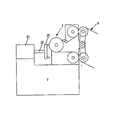
- the front schematic diagram which shows the grinding
- the perspective view which expanded the principal part of the grinding
- the principal part sectional drawing which shows the slide fastener and support part which concern on the modification 1 of the grinding
- the principal part perspective view which shows the grinding
- the principal part perspective view which shows the grinding
- the principal part front view which shows the tension
- the principal part front view which shows the support part which concerns on the modification 5 of the grinding
- the front schematic diagram which shows the modification 6 of the grinding
- polishing apparatus which concerns on the 2nd Example The principal part expanded sectional view of the grinding
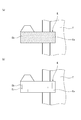
- (A) is an enlarged view of the polished surface of the fastener element before being polished by the polishing apparatus of the present invention
- (b) is an enlarged view of the polished surface of the fastener element after being polished by the polishing apparatus of the present invention. is there.
- (A) is an enlarged photograph of the polished surface of the fastener element before being polished by the polishing apparatus of the present invention
- (b) is an enlarged photograph of the polished surface of the fastener element after being polished by the polishing apparatus of the present invention. is there.
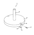
- the perspective view of the polish device concerning a prior art.
- upstream side means the upstream side in the conveyance direction of the slide fastener
- downstream side means the downstream side in the conveyance direction of the slide fastener
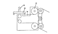
- FIG. 1 is a schematic front view showing a polishing apparatus according to a first embodiment of the present invention.
- the polishing apparatus 1 supports the fastener element E when the fastener element E is polished and the polishing portion 2 that polishes the fastener element E of the slide fastener S in the transport path of the slide fastener S.
- the polishing unit 2 is fixed to a column 6 protruding upward from the upper surface of the gantry 7, and includes a motor 21, a rotating shaft 22 connected to the motor 21, and a plate fixed to the tip of the rotating shaft 22. Has 23.
- the motor 21 of the polishing unit 2 is fixed to the pillar 6 described above.
- the rotating shaft 22 of the polishing unit 2 is on the output end side of the motor 21 and has a posture extending downward (vertical direction).
- the rotating shaft 22 rotates when the motor 21 is driven.
- the plate body 23 rotates in the horizontal plane together with the rotation shaft 22 when the rotation shaft 22 rotates.
- a polishing member 25 described later is fixed to the plate body 23.
- a frame 8 is fixed to the upper surface of the gantry 7, and a support unit 3, a transport unit 5, and a tension applying unit 4 are attached to the frame 8.
- the tension applying unit 4 is disposed on the most upstream side of the transport path.
- the transport unit 5 is disposed on the most downstream side of the transport path. Therefore, the support unit 3 is disposed between the tension applying unit 4 and the transport unit 5 in the transport path.
- the polishing unit 2 and the support unit 3 are arranged to face each other in the vertical direction with the conveyance path interposed therebetween. Note that the vertical direction of the polishing apparatus coincides with the front and back direction of the slide fastener.
- the support unit 3 includes a support roller 31, and the support roller 31 is supported by the frame 8 via the support roller rotation shaft 32 and rotates around the support roller rotation shaft 32.
- the support roller rotation shaft 32 of the support unit 3 is in a posture extending in a direction (horizontal direction) orthogonal to the rotation shaft 22 of the polishing unit 2 (that is, the rotation shaft of the polishing member).
- a slide fastener S is wound around the peripheral surface of the support roller 31.
- the support roller 31 rotates clockwise about the support roller rotation shaft 32.
- the rotation direction of the support roller 31 is not limited to the clockwise direction, and can be arbitrarily set depending on the configuration as long as the slide fastener is moved to the downstream side of the conveyance path.
- the transport unit 5 includes a transport roller shaft 52 supported by the frame 8, a transport roller 51 that rotates around the transport roller shaft 52, and a pressing roller 54 that presses the slide fastener S toward the transport roller 51.
- the transport roller shaft 52 is connected to a motor (not shown). By driving the motor, the transport roller 51 rotates about the transport roller shaft 52, and the slide fastener S is transported to the downstream side of the transport path.
- the conveyance speed of the slide fastener may be ensured that the entire fastener element E is polished by the polishing member 25 together with the rotation speed of the polishing member 25. For example, when the rotation speed of the polishing member is 5000 to 10,000 rpm And 2.5 to 5.0 m / min.
- the pressing roller 54 is pressed by the arm 53 in the direction of moving toward the conveying roller 51. Note that the pressing roller 54 may be pushed in the direction of moving toward the conveying roller 51 by a biasing member such as a spring.
- a guide roller 44 that guides the conveyance of the slide fastener S is disposed between the support unit 3 and the conveyance unit 5 in the conveyance path.
- the guide roller 44 is disposed below the uppermost portion of the support roller 31 of the support portion 3. Therefore, the slide fastener S passes through the uppermost portion of the support roller 31 of the support portion 3, and is then conveyed downward toward the guide roller 44 along the peripheral surface of the support roller 31. .
- the slide fastener S is prevented from floating upward between the support part 3 and the transport part 5, and the posture of the slide fastener S is not disturbed. That is, the slide fastener S is prevented from moving away from the support portion 3, and the posture in which the fastener element E is polished is stabilized.
- the tension applying unit 4 includes a shaft supported by the frame 8, a press receiving roller 41 that rotates around the shaft, and a press roller 42 that presses the slide fastener S toward the press receiving roller 41.
- the presser receiving roller 41 of the tension applying unit 4 is freely rotated about the shaft by a frictional force caused by contact with the slide fastener S.
- the pressing roller 42 is pressed in a direction of moving toward the presser receiving roller 41 by the arm 43. Note that the pressing roller 42 may be pushed toward the press receiving roller 41 by a biasing member such as a spring.
- FIG. 2 is an enlarged perspective view of a main part of the polishing unit.
- the polishing unit 2 includes a plate body 23 that is fixed to the tip of the rotating shaft 22 and that can rotate together with the rotating shaft 22.
- the plate body 23 is a disc extending in the radial direction about the rotation shaft 22.
- a protrusion 24 is fixed to the peripheral edge of the plate body 23.
- the protrusion 24 protrudes below the lower surface of the plate body 23.
- a polishing member 25 for polishing the fastener element E is fixed to the tip of the protrusion 24.
- the polishing member 25 can be fixed by any current method, but may be performed, for example, by adhesion using an adhesive.
- the polishing member is made of diamond.
- the protrusion 24 is fixed to the plate body 23 with a stopper (screw) 27. That is, the protrusion 24 can be attached to and detached from the plate body 23. Therefore, when it is necessary to replace the polishing member 25, the polishing member 25 is removed from the plate body 23 together with the protrusions 24 by loosening the stopper 27. In this way, it is possible to replace the abrasive member, which is a wear product, in a simple manner.
- the hole 26 shown in FIG. 2 is a hole through which the stopper 27 is inserted, and the protrusion 24 is fixed to the plate body 23 by the stopper 27 being passed through the hole 26 and tightened to the plate body 23.
- Rotating shaft 22 preferably rotates at 5000 rpm or more, for example, rotates at 5000 rpm to 10000 rpm.
- the polishing section 2 has a plurality (two in this embodiment) of polishing members 25. That is, a plurality of (two) protrusions 24 are fixed to the plate. A polishing member 25 is fixed to the tip of each protrusion 24.
- the protrusions 24 are arranged at a predetermined interval in the circumferential direction of the plate body. In consideration of the balance when rotating, in the illustrated example, they are arranged at an angle of 180 degrees.
- the number of protrusions 24 and polishing members 25 is not limited to two, but may be three for each 120 degree angle or four for each 90 degree angle.
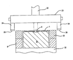
- FIG. 3 is a cross-sectional view of main parts of a polishing unit and a support unit in the polishing apparatus according to the first embodiment
- FIG. 4 is an enlarged cross-sectional view of main parts of the polishing unit and the support unit shown in FIG.
- the axis of the rotating shaft 22 of the polishing member 25 extends in parallel to the direction perpendicular to the axis of the rotating shaft of the support roller 31 of the support portion 3 (orthogonal direction).
- the rotating shaft 22 of the polishing member 25 extends parallel to the vertical direction with respect to the surface (upper surface) of the fastener element E with which the polishing member 25 is in contact.
- the polishing member 25 rotates together with the rotating shaft 22, the polishing member 25 is arranged in a direction (horizontal direction) parallel to the surface (upper surface) of the fastener element E as indicated by a virtual line (two-dot chain line) in FIG. Moving.
- the rotating shaft 22 of the polishing member 25 is described as an example connected directly to the motor 21, but the rotating shaft of the polishing member is perpendicular to the front or back surface of the fastener element E with which the polishing member is in contact. If it comprises so that it may extend, the rotating shaft of the grinding
- a mechanism for transmitting the rotational driving force from the motor to the rotating shaft is disposed between the driving shaft of the motor and the rotating shaft of the polishing member.
- the polishing surface of the polishing member 25 is preferably a flat polishing surface, but may be a curved surface.
- the polishing member 25 moves, if the polishing member 25 moves in a direction parallel to the surface to be polished of the fastener element, the surface to be polished of the fastener element can be polished flat.
- the support portion 3 includes a first member 31 composed of the above-described support roller 31 and a second member composed of a plate material arranged to face the peripheral surface of the support roller 31. 33. Between the first member 31 and the second member 33, there is a gap through which the fastener tape T of the slide fastener S can pass. When the fastener tape T passes through the gap, the first member 31 (the first surface of the first member) faces the back surface of the fastener tape T. Further, the second member 33 (the second surface of the second member) faces the surface of the fastener tape T. The second member 33 covers the surface of the fastener tape T from the outside in the radial direction of the support roller 31.
- a guide groove 34 that extends in the circumferential direction of the support roller 31 and accommodates the fastener element E and guides the movement of the fastener element E is formed on the peripheral surface of the support roller 31 (first member).
- the support roller 31 has a right side portion and a left side portion with the guide groove 34 interposed therebetween.
- the second member 33 has a right portion that faces the right portion of the support roller 31 and a left portion that faces the left portion of the support roller 31. There is a gap through which the fastener element E can pass between the right part and the left part of the second member 33.
- the guide groove 34 accommodates and guides the engaged fastener element E. At this time, the fastener element E is in contact with the support surface 34a which is the bottom surface of the guide groove 34.
- the support surface 34a receives a vertical pressing force from the polishing member 25. Therefore, the posture of the fastener element E is not displaced (moved away from the polishing member 25) during polishing. Further, both side walls of the guide groove 34 receive a horizontal pressing force (force dragged by the polishing member 25) from the polishing member 25 when the polishing member 25 contacts the fastener element E. Therefore, the posture of the fastener element E is prevented from being displaced (meandering along the peripheral surface of the first member 31) during polishing.
- the fastener element E has a front side portion arranged on the front side of the fastener tape T and a back side portion arranged on the back side of the fastener tape T.
- the back side portion (the front side portion when the back surface of the fastener element E is polished) is accommodated in the guide groove 34, and the front side portion of the fastener element E is positioned on the right side of the second member 33. It is exposed between the part and the left part. Therefore, the front side portion of the fastener element E is in contact with the polishing member 25 so as to face the polishing member 25 of the polishing unit 2.
- the support roller rotating shaft 32 of the first member (support roller) 31 is supported by the frames 8 disposed on the left and right of the support roller 31. As shown in FIG. 3, the second member 33 is also supported by the frame 8.
- FIG. 5 shows a modification 1 of the polishing apparatus of the first embodiment, and is a cross-sectional view of a main part showing a slide fastener and a support part.
- the slide fastener T includes a fastener element E and a fastener tape T on one side that are not engaged with each other.
- the guide groove 34 formed in the first member (support roller) 31 has a width that can accommodate only the fastener element E on one side. Thus, only the fastener element E on one side is polished by the polishing member 25.
- the first member 31 has a right side portion and a left side portion with the guide groove 34 interposed therebetween.
- the second member 33 is disposed to face the left side portion of the first member 31. Between the left side portion of the first member 31 and the second member 33, there is a gap through which the fastener tape T can pass.
- the second member 33 is disposed to face the left side portion of the first member 31, and a gap for passing the fastener tape is formed on the left side.
- a gap for passing the fastener tape may be formed on the right side so as to face each other.
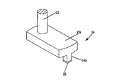
- FIG. 6 is a main part perspective view showing a second modification of the polishing apparatus of the first embodiment and showing a modification of the polishing section.
- the plate body 23 is formed of a disc, but may not be a disc.
- the plate body 23a is a rectangular plate.
- the rotating shaft 22 is fixed to one end side of the plate body 23a.
- a protrusion 24a is integrally formed on the other end side of the plate body 23a.
- the protrusion 24a cannot be removed from the plate body 23a.
- the polishing member 25 is fixed to the tip of the protrusion 24a in the same manner as in the first embodiment.
- the polishing member 25 polishes the fastener element E by rotating together with the rotary shaft 22 via the plate body 23a.
- the protrusion 24a may be eliminated.
- the polishing member (for example, sandpaper) 25 is directly fixed to the lower surface of the plate body 23a.
- FIG. 7 shows a third modification of the polishing apparatus of the first embodiment, and is a main part perspective view showing another modification of the polishing unit.
- the polishing member 25b may be directly fixed to the rotating shaft 22, as shown in FIG. In this case, there is no plate.
- the polishing member 25b may be a grindstone.
- FIG. 8 shows a modification 4 of the polishing apparatus of the first embodiment, and is a main part front view showing a modification of the tension applying section.
- the tension applying unit includes one guide roller 46 disposed on the upstream side of the transport path, the other guide roller 47 disposed on the downstream side of the transport path, and the guide rollers 46, 47.
- the dancer roller 45 is disposed between the two.
- the dancer roller 45 pushes the slide fastener S from above and bends the slide fastener S downward in a U shape.
- the dancer roller 45 serves as a weight for pushing the slide fastener S, and always applies tension to the slide fastener S.
- the slide fastener S is always in a tensioned state, and is thus wound around the support roller 31 without being loosened.
- FIG. 9 and 10 show a fifth modification of the polishing apparatus of the first embodiment
- FIG. 9 is a front view of a main part showing a modification of the support part
- FIG. 10 is a main part showing a modification of the support part. It is sectional drawing.
- the support portion 3 is composed of a roller, but the support portion 3a may be formed of a plate instead of a roller as shown in FIG. In this case, the axis of the rotating shaft 22 of the polishing member extends parallel to the direction perpendicular to the surface of the plate.
- the support portion 3a includes a support plate 31a serving as a first member on which the slide fastener S is placed, and a second member 33a.
- the support plate 31a is supported by the frame 8, and the second member 33a is supported by the support plate 31a.
- a guide groove 34 for receiving and guiding the fastener element E is formed on the upper surface of the support plate 31a as described above.
- the support plate 31a has a right side portion and a left side portion with the guide groove 34 interposed therebetween.
- the second member 33a has a right part facing the right part and a left part facing the left part.
- FIG. 11 is a schematic front view showing a sixth modification of the polishing apparatus according to the first embodiment. If the rotation shaft 22 of the polishing member is configured to extend in parallel with the direction perpendicular to the support portion 3, the arrangement of the rotation shaft 22 of the polishing member is arbitrary.
- FIG. 12 is a schematic front view showing a polishing apparatus according to a second embodiment of the present invention.
- FIG. 13 is an enlarged cross-sectional view of a main part of a polishing section and a support section (first support roller) in the polishing apparatus.
- 14 is an enlarged cross-sectional view of a main part of a polishing portion and a support portion (second support roller) in the polishing apparatus.
- the support portion 13 of the polishing apparatus 101 of the second embodiment has a first support roller 131 and a second support roller 132.
- the first support roller 131 is disposed on the upstream side of the transport path.
- the second support roller 132 is disposed downstream of the first support roller 131 in the transport path.
- the first support roller 131 and the second support roller 132 are arranged at substantially the same horizontal level in order to share the polishing unit 2.
- a guide roller 145 is disposed in the downstream proximity portion of the first support roller 131, and a guide roller 144 is disposed in the downstream proximity portion of the second support roller 132, respectively.
- These guide rollers 144 and 145 are arranged below the uppermost portions of the first support roller 131 and the second support roller 132 in the same manner as the guide roller 44 described above. Therefore, the slide fastener S passes through the uppermost portion of the first support roller 131 and then dives under the guide roller 145 along the peripheral surface of the first support roller 131.
- the slide fastener S is prevented from floating upward between the first support roller 131 and the second support roller 132 or between the second support roller 132 and the transport unit 5, so that the posture of the slide fastener S can be prevented. Do not disturb. That is, the slide fastener S is prevented from moving away from each of the first support roller 131 and the second support roller 132, and the posture in which the fastener element E is polished is stabilized.
- the guide roller 144 and the guide roller 145 are arranged at the same horizontal level. However, the guide roller 144 and the guide roller 145 may not be arranged at the same horizontal level as long as the above-described operation can be achieved.
- each of the first support roller 131 and the second support roller 132 of the support portion 13 has a first member 131, 132 facing each other with a gap through which the fastener tape T can pass.
- Two members 138 and 133 are provided.
- Each first member includes a first support roller 131 and a second support roller 132, respectively.
- the circumferential surfaces of the first support roller 131 and the second support roller 132 have guide grooves 139 and 134 for receiving and guiding the fastener element E, respectively.
- the guide groove 139 of the first support roller 131 has a first support surface 139a in contact with the fastener element E at the bottom of the groove.
- the first support surface 139a is inclined so as to protrude in a direction approaching the polishing member 25.
- the fastener element E has a base end Ea that contacts the edge of the fastener tape T, and a distal end (a portion that meshes with the opposing fastener element E) Eb that is away from the edge of the fastener tape T. .
- the first support surface 139a is inclined so as to rise, so that the tip Eb is directed upward toward the polishing member 25. Displaces to a tilted posture. Thereby, the tip end portion Eb of the fastener element E is polished by the polishing member 25.
- the guide groove 134 of the 2nd support roller 132 has the 2nd support surface 134a which contact
- the second support surface 134a is flat (a surface parallel to the rotation axis of the second support roller 132).
- the rotating shaft 22 of the polishing member extends in a direction perpendicular to the front or back surface of the fastener element E in a horizontal posture with which the polishing member 25 is in contact, as shown in FIGS. Yes.
- the polishing member can polish the fastener element E at two locations of the first support roller 131 and the second support roller 132. Therefore, it can grind
- FIGS. 15 and 16 linear polishing marks Ec extending in the length direction of the slide fastener S are formed on the surface (polishing surface) of the fastener element E polished by the polishing apparatuses 1 and 101 described above. Is done.
- FIG. 15 (a) shows that the surface (polishing surface) of the fastener element E is rough with fine irregularities before polishing with a dot pattern
- FIG. 15 (b) shows that the rough surface is It shows that a smooth glossy surface is obtained by polishing, and polishing marks Ec are formed on the glossy surface.
- a slide fastener element polishing apparatus for polishing a fastener element E in a slide fastener S having a fastener tape T and a fastener element E attached to the fastener tape T and having a front surface and a back surface.
- a support portion 3, 3a, 13 that is disposed along the path and the transport path, and is disposed so as to face either one of the back surface and the front surface of the fastener element E so as to support the posture of the fastener element E;
- the polishing units 2, 2a, 2b are arranged opposite to the support units 3, 3a, 13 across the conveyance path.
- the polishing units 2, 2a, 2b are fixed to the rotary shaft 22 and the rotary shaft 22.
- the rotating member 22 has a polishing member 25 that can be rotated by rotating, and the polishing member 25 is in contact with either the front surface or the back surface of the fastener element E, and the fastener Polishing the front or back surface of Remento E, it characterized the rotary shaft 22 of the polishing member 25 extends parallel to the direction perpendicular to the supporting portion 3, 3a, 13.
- the rotating shaft 22 of the polishing member 25 extends in parallel with the direction perpendicular to the support portions 3, 3a, 13, and the polishing member 25 is in contact with the front surface or the back surface of the fastener element E for polishing.
- the polishing member 25 can approach or be separated from the surface of the fastener element E by a straight track when the fastener element E is polished. As a result, the surface of the fastener element E is not cut into a curved shape. Therefore, the quality of the product is not deteriorated after polishing.
- the polishing portions 2 and 2a have plate bodies 23 and 23a that are fixed to the rotary shaft 22 and extend in a direction perpendicular to the axial direction of the rotary shaft 22, and the polishing member 25 is It is characterized by being fixed to the plate bodies 23 and 23a.
- the polishing portions 2 and 2a are fixed to the rotary shaft 22 and have plate bodies 23 and 23a extending in a direction perpendicular to the axial direction of the rotary shaft 22, and the polishing member 25 is attached to the plate bodies 23 and 23a. Since it is fixed, the polishing member 25 can be easily attached to the rotating shaft 22.
- the polishing portions 2 and 2a have protrusions 24 and 24a protruding from the plates 23 and 23a, and the polishing member 25 is attached to the tips of the protrusions 24 and 24a. It is characterized by.
- the polishing member 25 is attached to the tips of the protrusions 24 and 24a, the minimum polishing member 25 can be disposed in order to polish the fastener element E. Therefore, the manufacturing cost of the slide fastener is reduced.
- the plate body 23 is a disk extending in the radial direction of the rotation shaft 22 from the center of the rotation shaft 22, and a plurality of polishing members 25 are arranged along the peripheral edge of the plate body 23. Thus, they are arranged at a predetermined interval.
- the fastener element E can be polished with high efficiency.
- the plate body 23a is a rectangular plate extending from the center of the rotation shaft 22 in the radial direction of the rotation shaft 22, and one end of the plate body 23a is fixed to the rotation shaft 22.
- the polishing member 25 is disposed at the other end of the plate body 23a.
- the plate body may be a rectangular plate, the degree of freedom in designing the polishing portion is improved.
- the polishing member 25 is made of diamond.
- the polishing member 25 is made of diamond and has a high hardness, the fastener element E can be reliably polished.
- the slide fastener S has a pair of fastener tapes T and fastener elements E attached to opposite edges of the fastener tape T, and the support part 3 is in a meshed state.
- the fastener element E is supported.
- the support element 3 supports the engaged fastener element E, the engaged fastener element E can be polished simultaneously. Therefore, it can grind
- the support portions 3, 3a, and 13 have the support surfaces 34a, 134a, and 139a that are in contact with either the back surface or the front surface of the fastener element E.
- the support portions 3, 3a, 13 have the support surfaces 34a, 134a, 139a that contact the back surface or the front surface of the fastener element E, so that when the fastener element E contacts the polishing member 25, the fastener element E Even if it is pushed by the polishing member 25 and tries to move to the opposite side of the polishing member 25, the posture of the fastener element E can be prevented from being disturbed by the support from the support surfaces 34a, 134a, 139a.
- the support portions 3, 3a, 13 have guide grooves 34, 134, 139 for guiding the movement of the fastener element E, and the bottom surfaces of the guide grooves 34, 134, 139 are supported. It becomes the surface 34a, 134a, 139a, It is characterized by the above-mentioned.
- the support portions 3, 3a, 13 have guide grooves 34, 134, 139 for guiding the movement of the fastener element E, and the bottom surfaces of the guide grooves 34, 134, 139 are the support surfaces 34a, 134a, Therefore, when the fastener element E comes into contact with the polishing member 25, the guide grooves 34, 134, 139 can be moved even if the fastener element E is dragged by the polishing member 25 and moves in the rotational direction of the polishing member 25 together with the polishing member 25. Due to this limitation, the posture of the fastener element E can be prevented from being disturbed.
- the support portions 3 and 13 have a rotation shaft (support roller rotation shaft) 32 extending in a direction perpendicular to the rotation shaft of the polishing portion, and this rotation shaft (support roller rotation shaft). )
- a roller (supporting roller) 31 that is rotatable about 32.
- the support portions 3 and 13 are rotatable rollers, the fastener chain can be conveyed quickly. Further, the slide fastener S is wound around the rollers (support rollers) 31, 131, and 132, is given a tension, and has a stable posture. Therefore, the posture of the slide fastener S is not disturbed when being polished.
- the support portions 3 and 13 include the first members 31, 31 a, 131, 132 having the first surface and the second members 33, 33 a, 138, 133 having the second surface.
- the first members 31, 31a, 131, 132 and the second members 33, 33a, 138, 133 are arranged to face each other across the transport path, and the first members 31, 31a, 131, 132
- the second surface is opposed to the surface of the fastener tape T.
- the support portions 3 and 13 include first members 31, 31 a, 131 and 132 and second members 33, 33 a, 138 and 133, and the first members 31, 31 a, 131 and 132 and the first members There is a gap through which the fastener tape T can pass between the two members 33, 33a, 138, 133, and the first surface of the first member 31, 31a, 131, 132 when the fastener tape T passes through the gap.
- the second surface of the second members 33, 33a, 138, 133 is opposed to the surface of the fastener tape T, so that the polishing member 25 does not come into contact with the fastener tape T.
- Tape T can be protected. Therefore, the fastener tape T is not damaged.
- the support unit 13 includes a first roller (first support roller) 131 and a second roller (second support roller) 132, and the first roller (first support roller). 131 is characterized in that it is disposed upstream of the second roller (second support roller) 132 in the transport path.
- the support portion 13 has two rollers (first support roller 131 and second support roller 132) arranged at the front and rear in the transport path, the polishing member 25 is provided at two locations on the support portion 13. , The fastener element E can be polished. Therefore, it can grind
- the support portion 13 includes the first support surface 139a for supporting the fastener element E in the first posture and the first support surface for supporting the fastener element E in the second posture.
- the first support surface 139a is inclined in a direction approaching the polishing member 25, the second support surface 134a is flat, and the fastener element E is an edge of the fastener tape T.
- the first support surface 139a displaces the tip end portion Eb of the fastener element in a direction approaching the polishing member 25, and has a base end portion Ea in contact with the portion and a tip end portion Eb separated from the edge portion. To do.
- the polishing apparatus can polish only the surface of the fastener element E on the tip end portion Eb side. Since the fastener element E is curved so that the tip side is tapered, it may not be polished by polishing the entire surface. With this configuration, the tip end portion Eb can be reliably polished by changing the posture of the tip end portion Eb.
- the first support surface 139a is formed on the first support roller 131, and the second support surface 134a is formed on the second support roller 132. .
- the polishing apparatus further includes a slide fastener S transfer portion 5 disposed downstream of the support portions 3 and 13 in the transfer path, and a support portion in the transfer path. It is arranged upstream of 3, 13 and has a tension applying portion 4 that applies tension to the slide fastener S.
- the polishing apparatus further includes the conveyance unit 5 of the slide fastener S and the tension applying unit 4 that applies tension to the slide fastener S. Therefore, the polishing apparatus transfers the slide fastener S to the support units 3 and 13. When conveying, tension can be easily applied so that the posture of the slide fastener S is not disturbed.
Landscapes
- Engineering & Computer Science (AREA)
- Mechanical Engineering (AREA)
- Finish Polishing, Edge Sharpening, And Grinding By Specific Grinding Devices (AREA)
- Grinding And Polishing Of Tertiary Curved Surfaces And Surfaces With Complex Shapes (AREA)
- Polishing Bodies And Polishing Tools (AREA)
Priority Applications (3)
| Application Number | Priority Date | Filing Date | Title |
|---|---|---|---|
| EP17001639.8A EP3305469B1 (fr) | 2012-05-11 | 2013-04-10 | Dispositif de polissage pour élément de fermeture à glissière |
| CN201380024524.8A CN104270988B (zh) | 2012-05-11 | 2013-04-10 | 拉链用链牙的研磨装置及拉链用链牙 |
| EP13787439.2A EP2848151B1 (fr) | 2012-05-11 | 2013-04-10 | Dispositif de polissage pour élément de fermeture à glissière |
Applications Claiming Priority (2)
| Application Number | Priority Date | Filing Date | Title |
|---|---|---|---|
| CN201210153833.2 | 2012-05-11 | ||
| CN201210153833 | 2012-05-11 |
Publications (1)
| Publication Number | Publication Date |
|---|---|
| WO2013168510A1 true WO2013168510A1 (fr) | 2013-11-14 |
Family
ID=49550563
Family Applications (1)
| Application Number | Title | Priority Date | Filing Date |
|---|---|---|---|
| PCT/JP2013/060866 Ceased WO2013168510A1 (fr) | 2012-05-11 | 2013-04-10 | Dispositif de polissage pour élément de fermeture à glissière, et élément de fermeture à glissière |
Country Status (4)
| Country | Link |
|---|---|
| EP (2) | EP3305469B1 (fr) |
| CN (1) | CN104270988B (fr) |
| TW (1) | TWI519249B (fr) |
| WO (1) | WO2013168510A1 (fr) |
Cited By (2)
| Publication number | Priority date | Publication date | Assignee | Title |
|---|---|---|---|---|
| CN103586749A (zh) * | 2013-11-15 | 2014-02-19 | 驰马拉链(无锡)有限公司 | 金属拉链表面倒角抛光组件及倒角抛光机 |
| CN113953962A (zh) * | 2021-11-22 | 2022-01-21 | 温州润合服装辅料有限公司 | 一种拉链抛光机 |
Families Citing this family (4)
| Publication number | Priority date | Publication date | Assignee | Title |
|---|---|---|---|---|
| CN104690631B (zh) * | 2015-03-30 | 2017-03-15 | 广州市海珠区精诚拉链厂 | 一种拉链抛光机的抱紧机构及应用该机构的拉链抛光机 |
| CN104889844A (zh) * | 2015-06-02 | 2015-09-09 | 泰州市建业车件制造有限公司 | 一种汽车配件打磨装置 |
| CN105171548B (zh) * | 2015-09-30 | 2017-06-16 | 无锡市方正金属捆带有限公司 | 钢带表面处理装置 |
| CN109834573B (zh) * | 2019-03-25 | 2023-09-05 | 温州宏业精机科技有限公司 | 一种塑料拉链抛光机 |
Citations (7)
| Publication number | Priority date | Publication date | Assignee | Title |
|---|---|---|---|---|
| US2824319A (en) * | 1952-08-29 | 1958-02-25 | Nagele Karl Friedrich | Polishing machine for polishing the coupling links of separable slide fasteners |
| JPS511922Y1 (fr) * | 1971-06-17 | 1976-01-21 | ||
| JPS521590A (en) * | 1976-06-10 | 1977-01-07 | Kondo Gizaburo | Surface finishing method for small pieces of thin plate |
| JPH0890426A (ja) * | 1994-09-26 | 1996-04-09 | Toshiba Ceramics Co Ltd | 研磨装置 |
| GB2304149A (en) * | 1995-08-07 | 1997-03-12 | Ykk Europ Ltd | Zip fastener |
| JP2007276033A (ja) * | 2006-04-05 | 2007-10-25 | Koushin Special Glass Co Ltd | 研磨工具 |
| CN101461589A (zh) | 2007-12-18 | 2009-06-24 | 福建浔兴拉链科技股份有限公司 | 金属拉链及其表面加工设备和表面加工方法 |
Family Cites Families (4)
| Publication number | Priority date | Publication date | Assignee | Title |
|---|---|---|---|---|
| FR864956A (fr) * | 1939-12-29 | 1941-05-09 | Dispositif mécanique pour le polissage ou le brunissage d'objets métalliques ou autres | |
| CH300005A (de) * | 1950-12-06 | 1954-07-15 | W E Cuckson & Son Limited | Verfahren und Vorrichtung zum Polieren von Reissverschlussgliedern. |
| JPH1110432A (ja) * | 1997-06-17 | 1999-01-19 | Nissan Motor Co Ltd | 複合工具 |
| JP3713194B2 (ja) * | 2000-10-24 | 2005-11-02 | 株式会社スギノマシン | 平面用バニシング工具 |
-
2013
- 2013-04-10 EP EP17001639.8A patent/EP3305469B1/fr active Active
- 2013-04-10 CN CN201380024524.8A patent/CN104270988B/zh active Active
- 2013-04-10 EP EP13787439.2A patent/EP2848151B1/fr active Active
- 2013-04-10 WO PCT/JP2013/060866 patent/WO2013168510A1/fr not_active Ceased
- 2013-05-08 TW TW102116396A patent/TWI519249B/zh active
Patent Citations (7)
| Publication number | Priority date | Publication date | Assignee | Title |
|---|---|---|---|---|
| US2824319A (en) * | 1952-08-29 | 1958-02-25 | Nagele Karl Friedrich | Polishing machine for polishing the coupling links of separable slide fasteners |
| JPS511922Y1 (fr) * | 1971-06-17 | 1976-01-21 | ||
| JPS521590A (en) * | 1976-06-10 | 1977-01-07 | Kondo Gizaburo | Surface finishing method for small pieces of thin plate |
| JPH0890426A (ja) * | 1994-09-26 | 1996-04-09 | Toshiba Ceramics Co Ltd | 研磨装置 |
| GB2304149A (en) * | 1995-08-07 | 1997-03-12 | Ykk Europ Ltd | Zip fastener |
| JP2007276033A (ja) * | 2006-04-05 | 2007-10-25 | Koushin Special Glass Co Ltd | 研磨工具 |
| CN101461589A (zh) | 2007-12-18 | 2009-06-24 | 福建浔兴拉链科技股份有限公司 | 金属拉链及其表面加工设备和表面加工方法 |
Non-Patent Citations (1)
| Title |
|---|
| See also references of EP2848151A4 |
Cited By (3)
| Publication number | Priority date | Publication date | Assignee | Title |
|---|---|---|---|---|
| CN103586749A (zh) * | 2013-11-15 | 2014-02-19 | 驰马拉链(无锡)有限公司 | 金属拉链表面倒角抛光组件及倒角抛光机 |
| CN113953962A (zh) * | 2021-11-22 | 2022-01-21 | 温州润合服装辅料有限公司 | 一种拉链抛光机 |
| CN113953962B (zh) * | 2021-11-22 | 2022-04-19 | 温州润合服装辅料有限公司 | 一种拉链抛光机 |
Also Published As
| Publication number | Publication date |
|---|---|
| CN104270988A (zh) | 2015-01-07 |
| TW201350041A (zh) | 2013-12-16 |
| CN104270988B (zh) | 2016-12-14 |
| EP3305469B1 (fr) | 2023-06-21 |
| EP2848151A4 (fr) | 2016-03-09 |
| TWI519249B (zh) | 2016-02-01 |
| EP2848151B1 (fr) | 2017-11-15 |
| EP3305469A1 (fr) | 2018-04-11 |
| EP2848151A1 (fr) | 2015-03-18 |
Similar Documents
| Publication | Publication Date | Title |
|---|---|---|
| JP5026957B2 (ja) | 研磨装置及び研磨方法 | |
| CN102152206B (zh) | 研磨装置、研磨方法、按压研磨具的按压部件 | |
| US8152598B2 (en) | Substrate treating method and substrate treating apparatus | |
| CN104270988B (zh) | 拉链用链牙的研磨装置及拉链用链牙 | |
| JP4756709B2 (ja) | 研磨装置 | |
| WO2012046360A1 (fr) | Dispositif de transport de verre laminé et dispositif de chanfreinage équipé d'un tel dispositif | |
| US20110003540A1 (en) | Polishing apparatus | |
| US8814635B2 (en) | Substrate polishing method and device | |
| JPH081494A (ja) | ウエハー材縁端部研磨装置 | |
| KR101523815B1 (ko) | 판상체의 연마 장치 및 판상체의 연마 방법 | |
| JP2014213419A (ja) | ガラス板端面加工方法、および、ガラス板端面加工装置 | |
| JPH11241231A5 (fr) | ||
| JP2017109295A (ja) | 研磨加工装置 | |
| KR20160125474A (ko) | 유리 처리 장치 및 방법 | |
| JP2008194765A (ja) | 刃物研磨装置 | |
| JP6786292B2 (ja) | 研磨装置 | |
| JP2001328051A (ja) | 被研磨物のエッジ部の研磨方法及びその研磨装置 | |
| JP5003990B2 (ja) | ガラス板の加工方法及びその装置 | |
| JP5295051B2 (ja) | バリ取りマシン | |
| KR20100026620A (ko) | 평판 유리용 벨트형 엣지 폴리싱 장치 | |
| JP2005014130A (ja) | 丸棒鋼の端面研削方法 | |
| JP5021996B2 (ja) | 端面研磨装置および端面研磨方法 | |
| JP6928311B2 (ja) | カード搬送装置 | |
| CN100513071C (zh) | 端面研磨装置及端面研磨方法 | |
| JP2001170856A (ja) | 曲面仕上げ装置 |
Legal Events
| Date | Code | Title | Description |
|---|---|---|---|
| 121 | Ep: the epo has been informed by wipo that ep was designated in this application |
Ref document number: 13787439 Country of ref document: EP Kind code of ref document: A1 |
|
| NENP | Non-entry into the national phase |
Ref country code: DE |
|
| REEP | Request for entry into the european phase |
Ref document number: 2013787439 Country of ref document: EP |
|
| WWE | Wipo information: entry into national phase |
Ref document number: 2013787439 Country of ref document: EP |
|
| NENP | Non-entry into the national phase |
Ref country code: JP |