WO2013171999A1 - Système de mesure - Google Patents
Système de mesure Download PDFInfo
- Publication number
- WO2013171999A1 WO2013171999A1 PCT/JP2013/002964 JP2013002964W WO2013171999A1 WO 2013171999 A1 WO2013171999 A1 WO 2013171999A1 JP 2013002964 W JP2013002964 W JP 2013002964W WO 2013171999 A1 WO2013171999 A1 WO 2013171999A1
- Authority
- WO
- WIPO (PCT)
- Prior art keywords
- sensor amplifier
- sensor
- measurement
- power consumption
- unit
- Prior art date
- Legal status (The legal status is an assumption and is not a legal conclusion. Google has not performed a legal analysis and makes no representation as to the accuracy of the status listed.)
- Ceased
Links
Images








Classifications
-
- G—PHYSICS
- G01—MEASURING; TESTING
- G01R—MEASURING ELECTRIC VARIABLES; MEASURING MAGNETIC VARIABLES
- G01R1/00—Details of instruments or arrangements of the types included in groups G01R5/00 - G01R13/00 and G01R31/00
- G01R1/30—Structural combination of electric measuring instruments with basic electronic circuits, e.g. with amplifier
-
- H—ELECTRICITY
- H04—ELECTRIC COMMUNICATION TECHNIQUE
- H04Q—SELECTING
- H04Q9/00—Arrangements in telecontrol or telemetry systems for selectively calling a substation from a main station, in which substation desired apparatus is selected for applying a control signal thereto or for obtaining measured values therefrom
-
- G—PHYSICS
- G01—MEASURING; TESTING
- G01H—MEASUREMENT OF MECHANICAL VIBRATIONS OR ULTRASONIC, SONIC OR INFRASONIC WAVES
- G01H11/00—Measuring mechanical vibrations or ultrasonic, sonic or infrasonic waves by detecting changes in electric or magnetic properties
-
- H—ELECTRICITY
- H03—ELECTRONIC CIRCUITRY
- H03M—CODING; DECODING; CODE CONVERSION IN GENERAL
- H03M1/00—Analogue/digital conversion; Digital/analogue conversion
- H03M1/12—Analogue/digital converters
-
- H—ELECTRICITY
- H04—ELECTRIC COMMUNICATION TECHNIQUE
- H04W—WIRELESS COMMUNICATION NETWORKS
- H04W52/00—Power management, e.g. Transmission Power Control [TPC] or power classes
- H04W52/02—Power saving arrangements
- H04W52/0209—Power saving arrangements in terminal devices
- H04W52/0225—Power saving arrangements in terminal devices using monitoring of external events, e.g. the presence of a signal
- H04W52/0229—Power saving arrangements in terminal devices using monitoring of external events, e.g. the presence of a signal where the received signal is a wanted signal
- H04W52/0235—Power saving arrangements in terminal devices using monitoring of external events, e.g. the presence of a signal where the received signal is a wanted signal where the received signal is a power saving command
-
- H—ELECTRICITY
- H04—ELECTRIC COMMUNICATION TECHNIQUE
- H04Q—SELECTING
- H04Q2209/00—Arrangements in telecontrol or telemetry systems
- H04Q2209/40—Arrangements in telecontrol or telemetry systems using a wireless architecture
-
- H—ELECTRICITY
- H04—ELECTRIC COMMUNICATION TECHNIQUE
- H04Q—SELECTING
- H04Q2209/00—Arrangements in telecontrol or telemetry systems
- H04Q2209/40—Arrangements in telecontrol or telemetry systems using a wireless architecture
- H04Q2209/43—Arrangements in telecontrol or telemetry systems using a wireless architecture using wireless personal area networks [WPAN], e.g. 802.15, 802.15.1, 802.15.4, Bluetooth® or Zigbee®
-
- H—ELECTRICITY
- H04—ELECTRIC COMMUNICATION TECHNIQUE
- H04Q—SELECTING
- H04Q2209/00—Arrangements in telecontrol or telemetry systems
- H04Q2209/80—Arrangements in the sub-station, i.e. sensing device
- H04Q2209/84—Measuring functions
- H04Q2209/845—Measuring functions where the measuring is synchronized between sensing devices
Definitions
- the present invention relates to a measurement system for measuring a physical quantity.
- Patent Document 1 is a technique for transmitting the actual sound (noise) when the noise level exceeds a regulation standard. Specifically, the noise level of the noise is measured via a microphone and a sound level meter, and if the noise level exceeds the regulatory standard, a call is established by PHS (Personal Handyphone System), and the worker uses the actual sound from the PHS. You can hear.
- PHS Personal Handyphone System
- Patent Document 2 discloses a sound field characteristic measurement system for accurately measuring the sound field characteristic of a measurement space such as a hall or a stadium. Understanding the sound field characteristics is an important element not only for music performance but also for realizing clear in-field broadcasting.
- Patent Document 3 discloses an environmental data collection and analysis device that can collect and analyze specific environmental data signals related to noise and vibration and display them on a printed document or screen. According to the technique of Patent Document 3, since the attributes of the graph line are changed so that environmental data signals outside the measurement target can be visually recognized, the measurement data regarding noise and vibration can be easily analyzed and the sound of the measurement target can be analyzed. It is considered that the sound and the sound outside the measurement target can be easily distinguished.
- measurement data may be lost. That is, wireless communication is more likely to cause communication failure than wired communication, and communication may be interrupted. If measurement data is lost in the middle of wireless communication (when measurement data is lost), the reliability of measurement is reduced. In addition, if the measurement data retransmission request is repeated, the communication speed cannot keep up with the accumulation of the measurement data, and the measurer cannot know the current measurement data and measurement information.
- Each of the following solving means can be a solving means in which the citation relationship and the subordinate relationship are appropriately changed.
- Solution 1 The measurement system of this solution is built in a sensor amplifier to which a sensor that outputs an analog signal corresponding to a physical quantity to be measured is connected, and converts the analog signal input from the sensor into a digital signal.
- a sensor amplifier side communication means that is built in the main body unit that is paired with the sensor amplifier, and a main body side communication means that receives the digital signal transmitted from the sensor amplifier using a wireless communication function; and Built-in data generation means for generating measurement data based on the received digital signal; Missing information notifying means for notifying the sensor amplifier of missing information representing the missing portion through the main body side communication means when the digital signal transmitted from the sensor amplifier is contained in the main body unit, and the sensor amplifier When the missing information is received from the main unit through the sensor amplifier communication means, the measurement data of the missing portion stored in the data storage means based on the
- the measurement system of this solving means includes a sensor amplifier.
- a sensor that outputs an analog signal corresponding to a physical quantity to be measured (information based on measurement of sound, vibration, temperature, humidity, pressure, etc.) is connected to the sensor amplifier.
- the sensor amplifier converts an analog signal input from the sensor into a digital signal, and stores the digital signal in a memory or the like as measurement data.
- the sensor amplifier transmits a digital signal to the outside of the sensor amplifier using a wireless communication function.
- the measurement system of the present means for solving comprises a main unit.
- the main unit is a device paired with the sensor amplifier.
- the main unit receives a digital signal transmitted from the sensor amplifier using a wireless communication function, and generates measurement data based on the received digital signal.
- the generated measurement data can be stored in, for example, a memory of the main unit, subjected to signal processing by the main unit, or displayed on the display unit of the main unit.
- the main unit notifies the sensor amplifier of missing information indicating the missing portion. Determination of whether or not a digital signal is missing can be made by confirming, for example, a frame number assigned to the digital signal.
- the missing information can be information including information such as a missing frame number.
- wireless communication is more likely to cause a communication failure than wired communication, and communication may be interrupted.
- the digital signal obtained by the measurement is lost in the middle of the wireless communication (when data is lost), the reliability of the measurement is lowered.
- it is important to monitor the current latest information but if the retransmission request for measurement data is repeated, the communication speed cannot keep up with the accumulation of measurement data, and the measurer will It becomes impossible to know the measurement information.
- wireless is accumulate
- the measurement data stored in the sensor amplifier is automatically retransmitted to the main unit. Therefore, even if a communication failure occurs and a part of the digital signal is lost, the stored measurement data is retransmitted to the main unit so that the lost digital signal can be recovered. Can do.
- Solution 2 The measurement system of the present solution is the solution 1, wherein the missing information notification means notifies the missing information after a series of reception of the digital signal by the main body side communication means is completed.
- the missing information is notified after a series of digital signals have been received. For this reason, the retransmission process is not executed until a series of digital signals are received, even if the digital signals are missing.
- the data to be transmitted is collected at the end and transmitted by radio.
- the real-time property is impaired and it takes time to acquire the data.
- the present solution has the effect of shortening the acquisition time of the final data while maintaining the real-time property by batch transferring only the missing portion data in the last batch transfer.
- Solution 3 The measurement system of the present solution is the solution 1, wherein the missing information notifying means notifies the missing information when the digital signal is determined to be missing, and notifies the missing information. However, if the measurement data of the missing portion has not been retransmitted, the retransmission request processing based on the missing information notification is terminated in a certain time, and the retransmission request based on the missing information notification is performed by the missing information notification means.
- the apparatus further includes continuous reception processing execution means for executing a continuous reception process for causing the main body side communication means to continuously receive a series of the digital signals when the processing is completed within a predetermined time.
- the main unit notifies the missing information when it is determined that the digital signal is missing, and the missing information is not retransmitted even though the missing information is notified.
- the retransmission request processing based on the notification is terminated in a certain time. Then, when the retransmission request process is completed in a certain time, a continuous reception process is performed in which a series of digital signals are continuously received.
- the main unit executes the retransmission request process when it is determined that there is a missing digital signal.
- the retransmission request process does not function due to some communication failure, the retransmission request process is terminated in a certain time without continuing indefinitely.
- the measurement system of the present solution is built in a sensor amplifier to which a sensor that outputs an analog signal corresponding to a physical quantity to be measured is connected, and includes a first sensor amplifier-side communication unit having a wireless communication function;
- a second sensor amplifier-side communication means that has a wireless communication function that is built in a sensor amplifier and consumes less power than the first sensor amplifier-side communication means, and a main body unit that is paired with the sensor amplifier, and has a wireless communication function
- a first main body side communication means configured to communicate with the first sensor amplifier side communication means, and wireless communication that is built in the main body unit and consumes less power than the first main body side communication means
- a second main body side communication means having a function and communicating with the second sensor amplifier side communication means, and being incorporated in the main body unit, When shifting from the normal power mode to the low power consumption mode in which the power consumption is lower than that of the normal power mode, to shift to the low power consumption mode through the first main body side communication means or the second main body side communication means.
- a low power consumption mode transition command notifying means for notifying the sensor amplifier of the low power consumption mode transition command, and the sensor amplifier, and the first sensor amplifier side communication means or the second sensor amplifier side communication means When receiving the notification of the low power consumption mode transition command from the main unit, the first sensor amplifier side communication means is shifted from the operation state to the stop state, and the operation state of the second sensor amplifier side communication means is maintained.
- a power consumption mode transition means; and built in the main unit, and the sensor amplifier is moved from the low power consumption mode to the normal state.
- the normal power mode shift command notifying means for notifying the sensor amplifier of a normal power mode shift command for shifting to the normal power mode through the second main body side communication means, and built in the sensor amplifier
- the normal power mode for causing the first sensor amplifier side communication means to shift from the stop state to the operation state It is a measuring system provided with the transfer means.
- the measurement system of this solving means includes a sensor amplifier.
- a sensor that outputs an analog signal corresponding to the physical quantity to be measured is connected to the sensor amplifier.
- the sensor amplifier includes first sensor amplifier-side communication means having a wireless communication function and second sensor amplifier-side communication means having a wireless communication function with lower power consumption than the first sensor amplifier-side communication means.
- the measurement system of the present means for solving comprises a main unit.
- the main unit is a device paired with the sensor amplifier.
- the main unit has a wireless communication function, and includes a first main body side communication means that performs communication in combination with the first sensor amplifier side communication means, and a wireless communication function that consumes less power than the first main body side communication means.
- a second main body side communication unit configured to communicate with the second sensor amplifier side communication unit.
- the sensor amplifier in order to realize power saving of the sensor amplifier, the sensor amplifier is shifted to the low power consumption mode, or the sensor amplifier is returned from the low power consumption mode to the normal power mode.
- the flow of processing when shifting to each mode is as follows.
- the main unit When shifting to low power consumption mode, the main unit notifies the sensor amplifier of a low power consumption mode shift command.
- the sensor amplifier receives a notification of the low power consumption mode transition command from the main unit, the sensor amplifier shifts the first sensor amplifier side communication means from the operating state to the stopped state, and changes the operating state of the second sensor amplifier side communication means. maintain.
- the reason for maintaining the operating state of the second sensor amplifier side communication means is to maintain the communication state with the main unit, and to return the first sensor amplifier side communication means from the stopped state to the operating state.
- the main unit When shifting to normal power mode, the main unit notifies the sensor amplifier of a normal power mode shift command.
- the sensor amplifier receives a notification of the normal power mode shift command from the main unit, the sensor amplifier shifts the first sensor amplifier side communication means from the stopped state to the operating state.
- the main unit may not need the measurement data for a while. If the main unit determines that the measurement data is unnecessary, the sensor amplifier is switched to the low power consumption mode. Can be made. If the main unit determines that measurement data is necessary again, the sensor amplifier can be shifted to the normal power mode.
- the power consumption of the sensor amplifier can be suppressed by shifting the first sensor amplifier side communication means to the stop state.
- the second sensor amplifier side communication means maintains the operating state. For this reason, the communication state between the main unit and the sensor amplifier is ensured, and even if the mode is shifted to the low power consumption mode, the cooperation between the main unit and the sensor amplifier is maintained.
- the second sensor amplifier side communication means is a low power consumption device, it does not hinder power saving.
- the measurement system of the present solution is the solution 4 in which the low power consumption mode is a first low power consumption mode and a second low power consumption mode in which the power consumption is lower than that of the first low power consumption mode.
- the sensor amplifier includes a main control unit that controls a measurement state of the sensor and a sub control unit that consumes less power than the main control unit, and the low power consumption mode transition command notification unit includes the sensor amplifier.
- the sensor amplifier is notified of a low power consumption mode transition command corresponding to the second low power consumption mode, and the low power consumption mode transition is performed.
- the stage shifts the first sensor amplifier side communication means from the operating state to the stopped state when receiving the notification of the low power consumption mode transition command corresponding to the first low power consumption mode, and the second low power consumption mode
- the main control means and the first sensor amplifier side communication means are shifted from the operating state to the stopped state.
- the sensor amplifier includes a main control unit (for example, a main microcomputer) that controls the measurement state of the sensor and a sub control unit (for example, a sub microcomputer) that consumes less power than the main control unit.
- a main control unit for example, a main microcomputer
- a sub control unit for example, a sub microcomputer
- the sensor amplifier is shifted to one of two low power consumption modes in order to realize power saving in accordance with the measurement scene.
- the flow of processing when shifting to the two types of low power consumption modes is as follows.
- the main body unit notifies the sensor amplifier of a low power consumption mode transition command corresponding to the first low power consumption mode when communication is stopped while the sensor connected to the sensor amplifier continues to measure the physical quantity. Further, the main unit notifies the sensor amplifier of a low power consumption mode transition command corresponding to the second low power consumption mode when communication is stopped while stopping the measurement of the physical quantity in the sensor connected to the sensor amplifier.
- the sensor amplifier When receiving the notification of the low power consumption mode transition command corresponding to the first low power consumption mode, the sensor amplifier shifts the first sensor amplifier side communication means from the operating state to the stopped state. In addition, when receiving the notification of the low power consumption mode transition command corresponding to the second low power consumption mode, the sensor amplifier causes the main control unit and the first sensor amplifier side communication unit to transition from the operating state to the stopped state.
- the first sensor amplifier side communication means when the mode is shifted to the first low power consumption mode, the first sensor amplifier side communication means is in a stopped state, so communication with the first sensor amplifier side communication means cannot be performed, but the main control means is in an operating state. Therefore, the measurement of the physical quantity by the sensor can be continued.
- both the main control unit and the first sensor amplifier side communication unit are in a stopped state, so communication with the first sensor amplifier side communication unit cannot be performed. Measurement of physical quantities will also stop.
- the main control unit and the first sensor amplifier side communication unit are shifted to the stopped state, the power consumption can be further reduced as compared with the case of shifting to the first low power consumption mode.
- Solution 6 The measurement system of this solution is built in a sensor amplifier to which a plurality of sensors that output an analog signal corresponding to a physical quantity to be measured are connected, and converts the analog signal input from the sensor into a digital signal.
- Conversion means, and sensor amplifier side arithmetic processing means which is incorporated in the sensor amplifier and which arithmetically processes digital signals corresponding to some of the plurality of sensors based on a setting content relating to a predetermined arithmetic processing arrangement
- a sensor amplifier-side communication means that is built in the sensor amplifier and transmits the uncalculated digital signal and the digital signal after the calculation processing to the outside of the sensor amplifier, and a body that is paired with the sensor amplifier Built-in unit and the uncalculated digital signal transmitted from the sensor amplifier
- the measurement system of this solving means includes a sensor amplifier.
- a plurality of sensors that output analog signals corresponding to the physical quantity to be measured are connected to the sensor amplifier. For this reason, the sensor amplifier performs multi-channel measurement.
- the sensor amplifier converts an analog signal input from the sensor into a digital signal.
- the sensor amplifier is configured based on a set content related to a predetermined calculation processing arrangement (for example, an arrangement on which side of the main body unit or the sensor amplifier executes which calculation processing).
- a digital signal corresponding to the sensor (for example, one channel in the case of three-channel measurement) is calculated. Then, the sensor amplifier transmits the uncalculated digital signal and the digital signal after the arithmetic processing to the outside of the sensor amplifier.
- the measurement system of the present means for solving comprises a main unit.
- the main unit is a device paired with the sensor amplifier.
- the main unit receives the uncalculated digital signal and the digital signal after the calculation process transmitted from the sensor amplifier. Then, the main unit performs arithmetic processing on the uncalculated digital signals (for example, the remaining two channels in the case of three-channel measurement) corresponding to the remaining sensors among the plurality of sensors among the received digital signals.
- the present solution it is possible to distribute the arithmetic processing between the main unit and the sensor amplifier, and it is possible to effectively use hardware resources.
- the data amount of the digital signal that has been subjected to arithmetic processing by the sensor amplifier is reduced depending on the content of the arithmetic processing, it can also contribute to the reduction of communication burden by executing the arithmetic processing by the sensor amplifier.
- the arithmetic processing is distributed for each channel corresponding to a plurality of sensors, the determination criteria when the arithmetic processing is distributed becomes clear, and the control processing can be simplified.
- the measurement system of the present solution is a measurement system in which a plurality of sensor amplifiers are connected to one main unit, and is connected to the sensor amplifier and outputs an analog signal corresponding to a physical quantity to be measured.
- a sensor that outputs a measurement start command to each of the plurality of sensor amplifiers when the sensor that outputs and the sensor connected to each of the plurality of sensor amplifiers is started to measure the physical quantity.
- a start command notifying unit and each of the plurality of sensor amplifiers are connected to the sensor amplifier that has received the notification when receiving a measurement start command from the main unit by the measurement start command notifying unit. It is a measurement system provided with the measurement execution means which makes the said sensor start measurement of a physical quantity.
- the measurement system of this solving means is a measurement system in which a plurality of sensor amplifiers are connected to one main unit.
- a sensor that outputs an analog signal corresponding to the physical quantity to be measured is connected to each of the plurality of sensor amplifiers.
- the main body unit notifies the measurement start command to each of the plurality of sensor amplifiers when the sensor connected to each of the plurality of sensor amplifiers starts measurement of the physical quantity.
- the sensor amplifier receives a measurement start command notification from the main unit, the sensor amplifier causes the sensor connected to the received sensor amplifier to start measuring the physical quantity.
- the measurement system of the present solution is a measurement system in which a plurality of main body units are connected via a predetermined network, and a sensor amplifier connected to each of the plurality of main body units, and the sensor amplifier A sensor that outputs an analog signal corresponding to the physical quantity to be measured and one of the plurality of main body units, and starts measuring the physical quantity in the sensor connected to the sensor amplifier.
- a measurement start command notifying means for notifying another main body unit of a measurement start command through the predetermined network, and when the measurement start command is received through the predetermined network Before being connected to the sensor amplifier connected to the main unit
- a measuring system comprising a measurement execution means for starting the measurement of the physical quantity sensor.
- the measurement system of this solving means is a measurement system in which a plurality of main body units are connected via a predetermined network.
- a sensor amplifier is connected to each of the plurality of main body units.
- a sensor that outputs an analog signal corresponding to the physical quantity to be measured is connected to the sensor amplifier.
- the main body unit when one of the plurality of main body units causes the sensor connected to each sensor amplifier to start measurement of the physical quantity, the main body unit notifies the other main body unit of a measurement start command via a predetermined network.
- the other main unit receives the measurement start command notification, the other main unit causes the sensor connected to the sensor amplifier connected to the notified main unit to start measuring the physical quantity.
- a measurement start command can be notified to another main unit through a predetermined network. Therefore, if the network environment is in place, one main unit is located at a remote location. Can be managed. For this reason, in this solution, a single main unit can operate a plurality of main units in conjunction with each other using a measurement start command, and manages remote main units, measuring units, sensors, etc. be able to.
- the invention disclosed above has the following effects.
- the sensor amplifier accumulates digital signals to be transmitted wirelessly as measurement data.
- the sensor amplifier receives notification of missing information from the main unit, the sensor amplifier retransmits the measurement data of the missing portion to the main unit. Even if there is data loss in communication, it can be compensated later.
- two different types of communication means are selectively used depending on the situation, so that power saving can be realized efficiently.
- the arithmetic processing means is provided in both the main unit and the sensor amplifier, the arithmetic processing can be distributed and hardware resources can be used effectively.
- a measurement start command from the main unit can be used to cause the sensors connected to the plurality of sensor amplifiers to start measurement, it is possible to perform measurement with control over time synchronization.
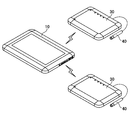
- FIG. 1 is a schematic diagram illustrating a measurement system 100 according to one embodiment.
- FIG. 2 is a perspective view showing the sensor amplifier 30 as seen from the back side.
- FIG. 3 is a diagram illustrating a connection example in which a plurality of sensor amplifiers 30 are wirelessly connected to one main unit 10.
- FIG. 4 is a diagram illustrating a connection example in which a plurality of main body units 10 are connected via the network 70.
- FIG. 5 is a block diagram schematically showing the configuration of the main unit 10 and the sensor amplifier 30.
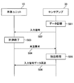
- FIG. 6 is a sequence diagram for explaining a first procedure example of buffering processing of measurement data
- FIG. 7 is a sequence diagram for explaining a second procedure example of the measurement data buffering process.
- FIG. 6 is a sequence diagram for explaining a first procedure example of buffering processing of measurement data
- FIG. 7 is a sequence diagram for explaining a second procedure example of the measurement data buffering process.
- FIG. 6 is a sequence diagram for explaining a first procedure example of buffering
- FIG. 8 is a sequence diagram for explaining a procedure example when shifting to the normal power mode or the low power consumption mode.
- FIG. 9 is a sequence diagram for explaining an example of a procedure of load distribution processing.
- FIG. 10 is a sequence diagram for explaining a procedure example of the network trigger process.
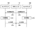
- FIG. 11 is a sequence diagram for explaining an example of the procedure of measurement processing when a plurality of sensor amplifiers 30 are connected to one main unit 10.
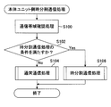
- FIG. 12 is a flowchart illustrating a procedure example of the time division communication processing on the main unit side.
- FIG. 13 is a flowchart illustrating a procedure example of the time division communication processing on the sensor amplifier side, and
- FIG. 14 is a diagram showing a state of indoor multipoint measurement, noise or vibration measurement.
- FIG. 1 is a schematic diagram illustrating a measurement system 100 according to one embodiment.
- the measurement system 100 is a device for measuring physical quantities such as sound, vibration, temperature, humidity, pressure, and the like, and includes a main unit 10 and a sensor amplifier 30.
- the main unit 10 and the sensor amplifier 30 transmit and receive data wirelessly.
- the main unit 10 is a tablet-type terminal (tablet terminal) having a flat rectangular parallelepiped shape and a size that can be carried by an operator.
- the main unit 10 also has a liquid crystal display device 11 for displaying various information (operation icons, information on digital signals, waveform data of various data, etc.) on the surface thereof.
- the liquid crystal display device 11 is provided with a touch panel for operating the measuring device 100, and the operator can operate the main unit 10 by touching the display on the screen.
- the main unit 10 has an inclined surface 11a at the peripheral edge thereof, and the entire thickness gradually decreases from the surface having the liquid crystal display device 11 toward the outside.
- the inclined surface 11a or the vicinity thereof serves as a holding unit for the operator to hold the main unit 10. Further, the corner portion of the main unit 10 is chamfered in an arc shape.
- the size of the main unit 10 can be, for example, a size of about A4 paper (about 210 mm long and about 297 mm wide) in plan view.
- an AC adapter terminal 13 On the right side surface of the main unit 10, there are provided an AC adapter terminal 13, a LAN (Local Area Network) port 14, a USB (Universal Serial Bus) port 14a, a card slot 15 into which a card-shaped recording medium is inserted, and the like. It has been.
- LAN Local Area Network
- USB Universal Serial Bus
- FIG. 2 is a perspective view showing the sensor amplifier 30 as viewed from the back side.
- the sensor amplifier 30 is a device having a rectangular parallelepiped shape and a size that can be carried by an operator.
- the input unit 24 includes four connectors 24a to 24d to which signals (analog signals and digital signals) representing physical quantities are input, and one connector 24e that outputs signals other than analog signals.
- Various sensors are connected to the four connectors 24a to 24d via cables. For this reason, measurement of four channels can be realized by the four connectors 24a to 24d.
- a measurement microphone 40 is connected to the connector 24c via a cable 41 and a connection plug 42.
- a vibration pickup, a temperature / humidity sensor, a pressure sensor, and the like can be connected to the input terminal of the sensor amplifier 30.
- an external device such as a speaker is connected to the connector 24e via a cable. For this reason, the connector 24e can output a signal other than an analog signal to an external device.
- the input / output assignment of each connector is not limited to the above example, and can be changed according to specifications and design.
- the sensor amplifier 30 has an inclined surface 32 at the periphery thereof, and the entire thickness increases from the surface having the opening hole 31 for confirming the light emitting state of the light emitting diode toward the outside. Is gradually getting thinner.
- the corner portion of the sensor amplifier 30 is chamfered in an arc shape.
- the worker attaches the sound level meter 46 to the sensor amplifier 30 and places the sound level meter 46 connected to the sensor amplifier 30 at the measurement point.
- the operator operates the main body unit 10 with the liquid crystal display device 11 of the main body unit 10 while holding the main body unit 10 while holding the vicinity of the inclined surface 11 a, and makes noise in the noise meter 46 connected to the sensor amplifier 30. Let's measure. Since the data measured by the sound level meter 46 is wirelessly transmitted to the main unit 10 via the sensor amplifier 30, the operator can check the measurement result on the spot while looking at the liquid crystal display device 11.
- FIG. 3 is a diagram illustrating a connection example in which a plurality of sensor amplifiers 30 are connected to one main unit 10 by radio.
- a measurement microphone 40 is connected to each sensor amplifier 30.
- the number of sensor amplifiers 30 can be increased as necessary to flexibly support multipoint measurement.
- FIG. 4 is a diagram illustrating a connection example in which a plurality of main body units 10 are connected via the network 70.
- a plurality of main body units 10 are prepared, and the main body units 10 are connected to each other via a network 70 such as a communication network of a mobile phone or the Internet.
- a network 70 such as a communication network of a mobile phone or the Internet.
- three main body units 10 (10A to 10C) are connected via a network 70, and the main body unit 10A is a management unit that manages the other main body units 10B and 10C.
- a sensor amplifier 30 with a noise level meter 46 is wirelessly connected to the main unit 10A to 10C.
- the main unit 10A can manage the other main units 10B and 10C by transmitting, for example, a control signal or the like via the network 70. Specifically, the main body unit 10A transmits a measurement start command to the other main body units 10B and 10C via the network 70 to perform measurement, or the other main body units 10B and 10C via the network 70 receive data. Measurement data can be acquired from other main unit 10B, 10C by transmitting a transmission request.
- FIG. 5 is a block diagram schematically showing the configuration of the main unit 10 and the sensor amplifier 30.
- the sensor amplifier 30 includes an input unit 24, an amplifier 70, an A / D converter 71, an arithmetic processing unit 72, a main control unit 73, a sub control unit 74, an external memory 75, an internal memory 76, a first wireless communication unit 91, a second The wireless communication part 92, the battery 93, and the power supply part 94 are provided.
- the input unit 24 is an interface through which input signals (including digital signals) representing physical quantities are input from various sensors connected to the sensor amplifier 30.
- an input signal may be input to the input unit 24 from an external device other than various sensors.
- the amplifier 70 is a device that amplifies an analog signal when the input signal input to the input unit 24 is an analog signal.
- the A / D converter 71 is a device that converts the analog input signal amplified by the amplifier 70 into a digital input signal (conversion means).
- the arithmetic processing unit 72 is an arithmetic processing device (sensor amplifier side arithmetic processing means) that performs arithmetic processing on the digital input signal converted by the A / D converter 71, and is configured by, for example, a DSP (Digital Signal Processor).
- the arithmetic processing in the arithmetic processing unit 72 is, for example, FFT (Fast Fourier Transform) or processing with content that is encoded or decoded for wireless communication. Note that the arithmetic processing unit 72 does not execute arithmetic processing when it is not necessary to execute arithmetic processing.
- the main control unit 73 is constituted by a CPU (Central Processing Unit, central processing unit) (main microcomputer, microprocessor, main control means).
- the main control unit 73 has a function of controlling various processes and operations performed by the sensor amplifier 30.
- the sub control unit 74 is constituted by a CPU (sub microcomputer, sub control means).
- the sub control unit 74 controls the operating state and the stopped state of the main control unit 73.
- the main control unit 73 and the sub control unit 74 also control the light emission state of the light emitting diode.
- the external memory 75 is an external storage device (data storage means) that can be attached to the sensor amplifier 30 and is, for example, a micro SD card.
- the internal memory 76 is a storage device (data storage means) provided in advance in the sensor amplifier 30, and is, for example, a ROM (Read Only Memory) or a RAM (Random Access Memory).
- the first wireless communication unit 91 is an interface for transmitting and receiving input signals (including digital signals) and various data using the wireless communication function with the first wireless communication unit 85 of the main unit 10 (on the first sensor amplifier side). Communication means).
- the first wireless communication unit 91 is a communication unit capable of high-speed communication. For example, Wi-Fi (Wi-Fi, registered trademark in Japan) using IEEE 802.11, which is a communication standard, can be applied. Note that the first wireless communication unit 91 is a communication unit with high power consumption because high-speed communication is possible.
- the second wireless communication unit 92 is an interface for transmitting and receiving input signals (including digital signals) and various data using the wireless communication function with the second wireless communication unit 86 of the main unit 10 (second sensor amplifier side). Communication means).
- the second wireless communication unit 92 is a communication unit having a communication speed slower than that of the first wireless communication unit 91.
- ZigBee ZigBee, registered trademark of Japan
- the second wireless communication unit 92 is a communication unit that consumes less power and consumes less power than the first wireless communication unit 91. That is, the first wireless communication unit 91 has a high transfer speed but high power consumption, and the second wireless communication unit 92 has a low transfer speed but low power consumption.
- the first power consumption (high power consumption) is higher than the second power consumption (low power consumption) (hereinafter the same).
- the high-speed communication is the first communication
- the low-speed communication is the second communication
- the first communication has a higher communication speed than the second communication (hereinafter the same).
- the battery 93 is constituted by a storage battery that can be repeatedly used by charging.
- the power supply unit 94 is a device serving as an operating source of the sensor amplifier 30.
- the power supply unit 94 When power is taken in from an AC adapter, a dry battery, or the like (not shown), necessary power is generated therefrom, and the generated power is transmitted to each unit of the wireless communication unit 30.
- Distribute. Battery 93 stores the electric power distributed from power supply unit 94.
- the sensor amplifier 30 is operated by electric power from the battery 93 and the power supply unit 94. Thus, since the sensor amplifier 30 includes the battery 93, for example, even when the power supply from the power supply unit 94 is temporarily stopped when the battery is replaced, the sensor amplifier 30 can operate continuously.
- the main control unit 73 of the sensor amplifier 30 is a control unit that controls the first wireless communication unit 91 and the second wireless communication unit 92 of the sensor amplifier 30.
- the sub control unit 74 controls the main control unit 73 and also controls the first wireless communication unit 91 and the second wireless communication unit 92.
- the sub control unit 74 is a control unit that consumes less power than the main control unit 73.
- the main control unit 73 controls the measurement state of the sensor connected to the sensor amplifier 30.
- the main unit 10 includes a control unit 81, an arithmetic processing unit 82, an external memory 83, an internal memory 84, a liquid crystal display device 11, a first wireless communication unit 85, a second wireless communication unit 86, a battery 87, a power supply unit 88, and a LAN port. 14 and a USB port 14a.
- the control unit 81 is configured by a CPU.
- the control unit 81 has a function of controlling various processes and operations performed by the main unit 10.
- the control unit 81 controls each unit of the main unit 10 based on an input signal from the liquid crystal display device 11 and also controls image display and the like of the liquid crystal display device 11.
- the arithmetic processing unit 82 is an arithmetic processing device (main body side arithmetic processing means) that performs arithmetic processing on the input signal received from the sensor amplifier 30, and is configured by a DSP, for example.
- the arithmetic processing unit 82 performs FFT (Fast Fourier Transform), or generates measurement data based on the received input signal (data generation means).
- the external memory 83 is an external storage device that can be attached to the main unit 10 and is, for example, an SD card.
- the internal memory 84 is a storage device provided in advance in the sensor amplifier 30 and is, for example, a ROM or a RAM.
- the internal memory 84 stores various application software for overall control of the measurement system 100 and for digitizing and analyzing digital data.
- the first wireless communication unit 85 is an interface for transmitting and receiving data using the sensor amplifier 30 and a wireless communication function (first main body side communication means).
- the first wireless communication unit 85 is a communication unit capable of high-speed communication.
- Wi-Fi Wi-Fi, registered trademark in Japan
- IEEE 802.11 which is a communication standard, can be applied.
- the first wireless communication unit 85 is a communication unit with high power consumption because high-speed communication is possible.
- the second wireless communication unit 86 is an interface for transmitting and receiving data using the wireless communication function with the sensor amplifier 30 (second main body side communication means).
- the second wireless communication unit 86 is a communication unit whose communication speed is slower than that of the first wireless communication unit 85.
- ZigBee ZigBee, registered trademark of Japan
- the second wireless communication unit 86 is a communication unit that consumes less power and consumes less power than the first wireless communication unit 85. That is, the first wireless communication unit 85 has a high transfer speed but high power consumption, and the second wireless communication unit 86 has a low transfer speed but low power consumption.
- the battery 87 is constituted by a storage battery that can be repeatedly used by charging.
- the power supply unit 88 is a device serving as an operation source of the main unit 10. When power is taken in from an AC adapter or a dry battery (not shown), the power unit 88 generates necessary power and distributes the generated power to each unit of the main unit 10. To do. Battery 87 stores the electric power distributed from power supply unit 88. The main unit 10 is operated by power from the battery 87 and the power supply unit 88. Thus, since the main unit 10 includes the battery 87, for example, even when the power supply from the power supply unit 88 is temporarily stopped when the battery is replaced, the main unit 10 can operate continuously.
- the LAN port 14 and the USB port 14a are interfaces for connecting the main unit 10 to external devices (not shown) (personal computers, devices on the network, and other measuring devices).
- FIG. 6 is a sequence diagram illustrating a first procedure example of buffering processing of measurement data.
- Step S01 When transmitting an input signal to the main unit 10, the sensor amplifier 30 stores the input signal in its own device (data storage means). Specifically, the sensor amplifier 30 stores an input signal as measurement data in the external memory 75 or the internal memory 76. At this time, transmission data (frame number information or the like) indicating the transmission order is added to the measurement data, and the measurement data is stored.
- data frame number information or the like
- Step S02 The sensor amplifier 30 transmits an input signal with transmission order information added to the main unit 10.
- the input signal may be transmitted by transferring the data stored in the external memory 75 or the internal memory 76 to the transmission buffer, or by directly transferring the input signal from the sensor to the transmission buffer. May be transmitted.
- Step S03 The main unit 10 continues to receive a series of input signals from the sensor amplifier 30, and when the measurement by the sensor amplifier 30 ends, the reception of the series of input signals ends.
- the main unit 10 can confirm whether there is any missing input signal by confirming the transmission order information added to the input signal.
- Step S04 In this case, the main unit 10 transmits a retransmission request for the input signals from the nth to the n + mth to the sensor amplifier 30 (missing information notification means).
- the retransmission request includes missing information indicating a missing portion of the input signal, and the main unit 10 notifies the sensor amplifier 30 of the retransmission request through the second wireless communication unit 86.
- Step S05 Based on the retransmission request from the main unit 10, the sensor amplifier 30 executes an extraction process for extracting the nth to n + mth input signal data from the external memory 75 or the internal memory 76.
- Step S06 The sensor amplifier 30 retransmits the extracted nth to n + mth input signal data to the main unit 10 (retransmission execution means). Specifically, the sensor amplifier 30 retransmits the extracted input signal data (measurement data) of the missing portion to the main unit 10 through the first wireless communication unit 91.
- the sensor amplifier 30 since the main unit 10 executes the retransmission request process after the reception of the series of input signals is completed, the sensor amplifier 30 is configured to transmit the data to be originally transmitted. Batch transmission of missing parts can be performed after transmission is completed. For this reason, it is possible to batch transfer only missing data in the last batch transfer, and it is possible to shorten the acquisition time of the final data while maintaining the real-time property.
- FIG. 7 is a sequence diagram illustrating a second procedure example of measurement data buffering processing.
- the procedure example in which batch transfer is performed after the real-time transfer is completed has been described.
- the second procedure example is a procedure example in which batch transfer is also executed during the real-time transfer.
- Step S10 When transmitting an input signal to the main unit 10, the sensor amplifier 30 stores the input signal in its own device (data storage means). Specifically, the sensor amplifier 30 stores an input signal as measurement data in the external memory 75 or the internal memory 76. At this time, transmission order information (frame number information or the like) indicating the order of transmission is added to the input signal, and the measurement data is stored.
- transmission order information frame number information or the like
- Step S12 The sensor amplifier 30 transmits an input signal with transmission order information added to the main unit 10.
- the main unit 10 can confirm whether there is any missing input signal by confirming the transmission order information added to the input signal.
- Step S ⁇ b> 14 the main unit 10 transmits a retransmission request for the nth to n + mth input signals to the sensor amplifier 30. That is, the main unit 10 executes the retransmission request process by notifying the sensor amplifier 30 of the missing information when it is determined that the input signal is missing. When the sensor amplifier 30 transmits the missing portion of the input signal data based on the retransmission request, the main unit 10 continues the input signal reception process.
- Step S16 On the other hand, when the sensor unit 30 does not retransmit the missing portion input signal even though the main unit 10 has transmitted a retransmission request, the main unit 10 monitors the latest measurement state.
- the retransmission request processing with 30 is timed out in a certain time (for example, about several seconds).
- Step S18 When the retransmission request process times out for a predetermined time, the main unit 10 executes a continuous reception process that continues to receive the latest input signal (a series of digital signals) from the sensor amplifier 30 (continue). Reception processing execution means). Specifically, the main unit 10 causes the first wireless communication unit 85 to continuously receive a series of input signals.
- the sensor amplifier 30 always stores measurement data (input signal) in the external memory 75 or the internal memory 76 for backup.
- Step S20 The main unit 10 continues to receive a series of input signals from the sensor amplifier 30, and when the measurement by the sensor amplifier 30 ends, the reception of the series of input signals ends.
- Step S22 Since the main unit 10 can grasp the missing portion of the input signal by confirming the transmission order information added to the input signal, the main unit 10 receives the nth to n + mth input signal data. Send a resend request to request resend only.
- Step S24 Based on the retransmission request from the main unit 10, the sensor amplifier 30 executes an extraction process for extracting the nth to n + mth input signal data from the external memory 75 or the internal memory 76.
- Step S26 The sensor amplifier 30 retransmits the extracted nth to n + mth input signal data to the main unit 10 (retransmission execution means).
- the latest measurement data can be continuously monitored while the real-time performance is further improved by executing the retransmission request processing when the data loss is found.
- the retransmission request processing is rounded up in a certain time, and the retransmission request processing is not continued indefinitely, and the real-time property by the retransmission request processing is impaired. Is avoiding.
- FIG. 8 is a sequence diagram for explaining a procedure example when shifting to the normal power mode or the low power consumption mode.
- Step S30 The main unit 10 requests the sensor amplifier 30 to transmit an input signal (data transmission request).
- Step S32 The sensor amplifier 30 transmits an input signal to the main unit 10 based on the data transmission request from the main unit 10. Data transfer is performed using the first wireless communication unit 85.
- Step S34 When the main unit 10 does not need an input signal for a while (for example, the time period between the bombardment in the case of measurement of the bombardment sound), the main unit 10 moves the sensor amplifier 30 from the normal power mode. It is determined to shift to the low power consumption mode in which the power consumption is lower than that in the normal power mode. In this case, the main unit 10 notifies the sub-control unit 74 of the sensor amplifier 30 of the sleep command (low power consumption mode transition command) with the content to be shifted to the low power consumption mode through the second wireless communication unit 86 (low power consumption). Power mode transition command notification means).
- Step S40 The sub-control unit 74 of the sensor amplifier 30 that has received the sleep command shifts only the main control unit 73 and the first wireless communication unit 91 or only the first wireless communication unit 91 of the own device from the operating state to the stopped state. .
- the first mode is a mode in which the first wireless communication unit 91 is shifted from the operating state to the stopped state, the main control unit 73 is operated, and the measurement state is maintained (measurement is continued by the sensor) (half-sleep).
- Mode first low power consumption mode.
- the second mode not only the first wireless communication unit 91 but also the main control unit 73 shifts from the operating state to the stopped state, and shifts the main control unit 73 to the non-measurement state (stops measurement by the sensor).
- Mode complete sleep mode; second low power consumption mode).
- the selection of the two types of modes is performed based on the mode selection information included in the sleep command.
- the sensor amplifier 30 receives the notification of the sleep command corresponding to the first low power consumption mode, the sensor amplifier 30 selects the first wireless communication unit 91. Transition from the operating state to the stopped state.
- the sensor amplifier 30 shifts the main control unit 73 and the first wireless communication unit 91 from the operating state to the stopped state.
- the main control unit 73 and the first wireless communication unit 91 of the sensor amplifier 30 can be shifted to the low power consumption mode (low power consumption mode transition means).
- the sub-control unit 74 and the second wireless communication unit 92 operate with low power consumption. Thereby, power consumption can be reduced significantly.
- Step S42 When the main unit 10 shifts the sensor amplifier 30 from the low power consumption mode to the normal power mode, the wake-up command (normal power mode shift command) for shifting to the normal power mode through the second wireless communication unit 86. Is transmitted to the sub-control unit 74 of the sensor amplifier 30 (normal power mode shift command notification means).
- Step S46 When receiving the wake-up command, the sub-control unit 74 of the sensor amplifier 30 shifts the main control unit 73 in the stopped state and the first wireless communication unit 91 in the stopped state from the stopped state to the operating state (normal power Mode transition means).
- the main control unit 73 and the first wireless communication unit 91 of the sensor amplifier 30 can be shifted to the normal power mode.
- the sensor amplifier 30 may shift from the low power consumption mode to the normal power mode after a fixed time has elapsed (for example, after several minutes or several hours) without receiving the wake-up command.
- Step S48 The sensor amplifier 30 notifies the state that the low power consumption mode has shifted to the normal power mode. As a result, the main unit 10 can recognize that the sensor amplifier 30 is in a state where it can accept a data transmission request (see step S30). After that, the main unit 10 can acquire an input signal (measurement data) through the above steps S30 and S32.
- the sensor amplifier 30 may be installed in an area where workers cannot enter or are difficult to enter.
- a wake-up command can be transmitted from the main unit 10 to cause the sensor amplifier 30 to start measurement.
- the sensor amplifier 30 can be operated only in order to save power consumption and to save power.
- FIG. 9 is a sequence diagram illustrating an example of a procedure for load distribution processing.
- the load distribution process is a process for distributing the load of the arithmetic processing (for example, FFT) by the sensor amplifier 30 and the main unit 10 operating in cooperation.
- a plurality of sensors are connected to the sensor amplifier 30, and the sensor amplifier 30 performs multi-channel measurement.
- Step S50 The sensor amplifier 30 executes a calculation amount determination process. Specifically, the sensor amplifier 30 determines whether or not the calculation amount exceeds a specified value (number of channels (number of input signals)). The calculation amount determination process is executed based on a setting content related to a predetermined calculation process arrangement.
- the setting content is information managed on the main unit 10 side, and information on the setting content is transmitted from the main unit 10 to the sensor amplifier 30 when executing the load distribution process. Information regarding the setting contents may be managed in the sensor amplifier 30.
- a specified value for example, 3 channels.
- Step S52 If the number of channels is greater than or equal to the predetermined number, the sensor amplifier 30 transmits an input signal for a specified value (for example, 2 channels) to the main unit 10.
- the input signal transmitted here is data that has not yet undergone arithmetic processing (uncalculated). Specifically, the sensor amplifier 30 transmits an uncalculated input signal to the main unit 10 through the first wireless communication unit 91.
- Step S54 The sensor amplifier 30 executes a calculation process in the calculation processing unit 72 of its own device (sensor amplifier side calculation processing means).
- the calculation process executed here is a calculation process of the input signal exceeding the specified value (for the remaining one channel).
- Step S58 The sensor amplifier 30 transmits the input signal for which the arithmetic processing has been completed to the main unit 10.
- the input signal transmitted here is data that has already been subjected to calculation processing (calculated). Specifically, the sensor amplifier 30 transmits the calculated input signal to the main unit 10 through the first wireless communication unit 91.
- the sensor amplifier 30 can also share the calculation processing. By decentralizing, hardware resources can be used effectively.
- FIG. 10 is a sequence diagram for explaining a procedure example of the network trigger processing.
- a plurality of main body units 10 are prepared.
- the plurality of main body units 10 are connected via a predetermined network (for example, the network 70).
- the network trigger process is a process in which a device belonging to the network starts operating based on a trigger (for example, a signal for starting measurement) generated on the network.
- a trigger for example, a signal for starting measurement
- any one of the plurality of main body units 10 serves as a management unit that manages other main body units.
- main body units 10 10A to 10C
- the left main body unit 10A is a management unit
- the right two main body units 10B and 10C are normal units managed by the main body unit 10A.
- a sensor amplifier 30 is wirelessly connected to each main unit 10.
- various sensors are attached to the sensor amplifier 30.
- Step S60 The main unit 10A transmits a measurement start command with a content for starting the measurement of the physical quantity to the main unit 10B and the main unit 10C via a predetermined network (measurement start command notifying unit).
- Step S62 When the main unit 10A transmits a measurement start command, the main unit 10A transmits a measurement start instruction (control signal) to the sensor amplifier 30 connected to the main unit 10A, and starts measurement related to the physical quantity.
- a measurement start instruction control signal
- Steps S64 and S66 When the main unit 10B and the main unit 10C receive the measurement start command, the main unit 10B and the main unit 10C transmit a measurement start instruction to the main unit 10B and the measurement unit connected to the main unit 10C.
- the sensor connected to 10C is started to measure physical quantities (measurement execution means).
- the remaining main unit 10B, 10C can be operated in conjunction with the information from the main unit 10A serving as a management unit,
- the main unit 10 and the sensor amplifier 30 in a remote place can be controlled efficiently.
- FIG. 11 is a sequence diagram illustrating an example of a procedure of measurement processing when a plurality of sensor amplifiers 30 are connected to one main unit 10.
- two sensor amplifiers 30 (30A, 30B) are connected to one main unit 10, and one main unit 10 manages two sensor amplifiers 30A, 30B.
- various sensors are attached to the sensor amplifiers 30A and 30B.
- Step S70 The main unit 10 transmits a measurement start command having a content for starting the measurement of the physical quantity to the sensor amplifier 30A (measurement start command notifying unit). Specifically, the main unit 10 notifies the measurement start command to the sensor amplifier 30 ⁇ / b> A through the first wireless communication unit 85.
- Step S72 At the same time, the main unit 10 transmits a measurement start command having the content for starting the measurement of the physical quantity to the sensor amplifier 30B (measurement start command notification means). Specifically, the main unit 10 notifies the measurement start command to the sensor amplifier 30 ⁇ / b> B through the first wireless communication unit 85.
- Steps S74 and S76 When receiving the measurement start command, the sensor amplifier 30A and the sensor amplifier 30B cause the sensors connected to the sensor amplifier 30A and the sensor amplifier 30B to start measuring physical quantities.
- Step S78 When the measurement of the physical quantity is started, the sensor amplifier 30A transmits an input signal to the main unit 10.
- Step S80 Similarly, when the measurement of the physical quantity is started, the sensor amplifier 30B transmits an input signal to the main unit 10.
- the main unit 10 transmits the measurement start command to the two sensor amplifiers 30A and 30B at the same time, the input signal may be received from the sensor amplifiers 30A and 30B at the same time. is assumed. As described above, when a plurality of sensor amplifiers 30 are connected to one main unit 10, the communication band may be insufficient. In this case, the following time-division communication process is executed.
- FIG. 12 is a flowchart illustrating a procedure example of the main unit side time division communication process.
- Step S100 The controller 81 of the main unit 10 executes a communication band confirmation process. This process is a process for confirming whether or not a communication band capable of simultaneously obtaining measurement data from all units can be secured when many sensor amplifiers 30 are connected to the main unit 10.
- Step S102 The control unit 81 confirms whether or not the execution condition for the time division communication process is satisfied. Specifically, it is confirmed whether or not a desired communication band is secured by the previous communication band confirmation process. As a result, when it is determined that the execution condition of the time division communication process is not satisfied (No), the control unit 81 executes step S104 next, and when it is determined that the execution condition of the time division communication process is satisfied (Yes), Next, the control unit 81 executes step S106.
- Step S104 The control unit 81 executes normal communication processing. When this process is executed, the control unit 81 receives an input signal from each of the sensor amplifiers 30 because a communication band in which measurement data can be simultaneously acquired from all units is secured.
- Step S106 The control unit 81 executes time division communication processing.
- the control unit 81 sequentially receives the input signal from each sensor amplifier 30 in a time-division manner because a communication band that can simultaneously acquire measurement data from all units cannot be secured. Receive.
- the control unit 81 transmits an input signal transmission execution request to each sensor amplifier 30 according to the divided time, or transmits an input signal transmission stop request. To do.
- the main unit 10 can select either normal communication processing or time-division transmission processing by repeatedly executing the above processing (steps S100 to S106).
- FIG. 13 is a flowchart illustrating a procedure example of the time division communication processing on the sensor amplifier side.
- Step S200 The main control unit 73 of the sensor amplifier 30 checks whether or not a transmission execution request has been received from the main unit 10. As a result, when it is determined that the transmission execution request is received from the main unit 10 (Yes), the main control unit 73 next executes step S202 and determines that the transmission execution request is not received from the main unit 10 (No), the main control unit 73 does not execute step S202.
- Step S202 The main control unit 73 executes an input signal transmission execution process. By this processing, an input signal is transmitted from the sensor amplifier 30 to the main unit 10.
- Step S204 The main control unit 73 checks whether or not a transmission stop request has been received from the main unit 10. As a result, when it is determined that a transmission stop request has been received from the main unit 10 (Yes), the main control unit 73 next executes step S206 and determines that a transmission stop request has not been received from the main unit 10 (No), the main control unit 73 does not execute step S206.
- Step S206 The main control unit 73 executes an input signal transmission stop process. By this process, when the input signal is transmitted to the main unit 10, the transmission of the input signal is stopped.
- the sensor amplifier 30 can execute the time division transmission process by repeatedly executing the above processes (steps S200 to S206).
- the main body unit 10 is each sensor. Measurement data (input signal) can be collected from the amplifier 30 in a time-sharing manner.
- FIG. 14 is a diagram showing a state of indoor multipoint measurement, noise or vibration measurement.
- Indoor multipoint measurement is measurement of noise, vibration, etc. in an apartment house 300 such as an apartment.
- noise and vibration in a building are measured from the outside of the apartment house 300, and measurement in a plurality of rooms is often simultaneously measured at multiple points. If they are on the same floor or adjacent floors, multiple points can be measured at the same time by routing the cable, but the labor of the worker is still considerable.
- simultaneous multipoint measurement of distant floors must be given up, and must be measured for each floor.
- the main unit 10 is arranged outside the apartment house 300, and the sensor amplifiers 30 to which the sound level meters 46 are attached are arranged on the second and fourth floors of the apartment house 300. Then, measurement data is transmitted from the sensor amplifier 30 to the main unit 10 by radio.
- the worker can monitor the status of the site in real time while checking the main unit 10. Moreover, when an abnormal noise source is discovered while monitoring on-site, the worker can add the sensor amplifier 30 with the sound level meter 46 attached at any time, and the measurement points can be increased flexibly. Points that are likely to cause noise can be additionally measured sequentially.
- the sensor amplifier 30 having the noise level meter 46 attached thereto is also arranged in the building 402 on the left side of the roadway 400 or in the building 404 on the right side of the roadway 400. Further, on both sides of the roadway 400, the sensor amplifier 30 to which the vibration level meter 48 is attached as well as the noise level meter 46 is disposed. For this reason, in this measurement example, it is possible to measure a wide range of the area facing the road.
- the measurement can be completed without causing missing measurement data by executing the above-mentioned real-time transfer or batch transfer. Can do.
- the sensor amplifier 30 stores a signal to be transmitted by wireless communication in its own device, it can flexibly cope with data loss in wireless communication.
- the main unit 10 and the sensor amplifier 30 can efficiently realize power saving by using two different types of wireless communication units depending on the situation.
- the sensor amplifier 30 can assist the arithmetic processing for the signal that cannot be processed, so that the arithmetic processing is distributed. Hardware resources can be used effectively. (4) Since measurement can be started by the sensors connected to the plurality of sensor amplifiers 30A and 30B by using a measurement start command from the main unit 10, a measurement with control over time synchronization should be performed. Can do.
- the disclosed invention can be implemented with various modifications without being limited to the above-described embodiments. Moreover, the invention can be applied to various measurement scenes other than the measurement scenes described above.
Landscapes
- Engineering & Computer Science (AREA)
- Computer Networks & Wireless Communication (AREA)
- Physics & Mathematics (AREA)
- General Physics & Mathematics (AREA)
- Signal Processing (AREA)
- Theoretical Computer Science (AREA)
- Arrangements For Transmission Of Measured Signals (AREA)
- Testing Or Calibration Of Command Recording Devices (AREA)
- Measurement Of Mechanical Vibrations Or Ultrasonic Waves (AREA)
Priority Applications (2)
| Application Number | Priority Date | Filing Date | Title |
|---|---|---|---|
| EP13790218.5A EP2851884B1 (fr) | 2012-05-18 | 2013-05-08 | Système de mesure |
| US14/401,971 US10139431B2 (en) | 2012-05-18 | 2013-05-08 | Measurement system |
Applications Claiming Priority (2)
| Application Number | Priority Date | Filing Date | Title |
|---|---|---|---|
| JP2012115000A JP5579775B2 (ja) | 2012-05-18 | 2012-05-18 | 計測システム |
| JP2012-115000 | 2012-05-18 |
Publications (1)
| Publication Number | Publication Date |
|---|---|
| WO2013171999A1 true WO2013171999A1 (fr) | 2013-11-21 |
Family
ID=49583428
Family Applications (1)
| Application Number | Title | Priority Date | Filing Date |
|---|---|---|---|
| PCT/JP2013/002964 Ceased WO2013171999A1 (fr) | 2012-05-18 | 2013-05-08 | Système de mesure |
Country Status (4)
| Country | Link |
|---|---|
| US (1) | US10139431B2 (fr) |
| EP (3) | EP3133826B1 (fr) |
| JP (1) | JP5579775B2 (fr) |
| WO (1) | WO2013171999A1 (fr) |
Cited By (2)
| Publication number | Priority date | Publication date | Assignee | Title |
|---|---|---|---|---|
| CN106663368A (zh) * | 2014-08-18 | 2017-05-10 | Ntn株式会社 | 便携型诊断用数据测定发送装置 |
| TWI773910B (zh) * | 2014-05-14 | 2022-08-11 | 美商應用材料股份有限公司 | 具有氣體分佈及個別泵送的批次固化腔室 |
Families Citing this family (6)
| Publication number | Priority date | Publication date | Assignee | Title |
|---|---|---|---|---|
| US11416123B2 (en) | 2014-03-14 | 2022-08-16 | Particle Measuring Systems, Inc. | Firmware design for facility navigation, and area and location data management of particle sampling and analysis instruments |
| AT517412B1 (de) * | 2015-07-03 | 2018-02-15 | Avl Ditest Gmbh | Tragbare Messsonde |
| JP6850551B2 (ja) * | 2016-05-19 | 2021-03-31 | サクラ精機株式会社 | 医療用機器のデータ通信システム |
| FR3097633B1 (fr) | 2019-06-19 | 2021-11-12 | Alliantech | Dispositif de mesure microphonique portatif |
| CN110530502A (zh) * | 2019-08-01 | 2019-12-03 | 深圳市无限动力发展有限公司 | 电机状态监测方法、装置、存储介质及计算机设备 |
| USD1054406S1 (en) * | 2021-09-09 | 2024-12-17 | Fluke Corporation | Handheld imager |
Citations (11)
| Publication number | Priority date | Publication date | Assignee | Title |
|---|---|---|---|---|
| JPH09130871A (ja) * | 1995-11-02 | 1997-05-16 | Yokogawa Electric Corp | 時系列データの送信装置 |
| JPH11355331A (ja) * | 1998-06-12 | 1999-12-24 | Nec Eng Ltd | 遠隔計測システムのデータ通信制御方法 |
| JP2001188980A (ja) * | 1999-12-28 | 2001-07-10 | Toshiba Corp | テレメータシステム |
| JP2002188953A (ja) | 2000-12-20 | 2002-07-05 | Fuji Electric Co Ltd | 騒音監視システム |
| JP2003006780A (ja) * | 2001-06-25 | 2003-01-10 | Nks:Kk | 計測データ伝送システム |
| JP2006064393A (ja) | 2004-08-24 | 2006-03-09 | Matsushita Electric Ind Co Ltd | 音場特性測定システム |
| JP2009049602A (ja) * | 2007-08-16 | 2009-03-05 | Canon Inc | 無線通信システム、無線通信装置及びその制御方法 |
| JP2009099040A (ja) * | 2007-10-18 | 2009-05-07 | Espec Corp | データ収集装置、データ収集方法、プログラム、およびプログラムを記録したコンピュータ読み取り可能な記録媒体 |
| JP2010078369A (ja) | 2008-09-24 | 2010-04-08 | Fuji Densetsu Kk | 環境データ収集解析装置 |
| JP2010114766A (ja) * | 2008-11-07 | 2010-05-20 | Univ Of Electro-Communications | 情報処理装置および方法、プログラム、並びに通信方法 |
| JP2011128791A (ja) * | 2009-12-16 | 2011-06-30 | Toshiba Corp | 管内計測システムおよび計測装置 |
Family Cites Families (9)
| Publication number | Priority date | Publication date | Assignee | Title |
|---|---|---|---|---|
| US4887162A (en) * | 1988-04-19 | 1989-12-12 | Ricoh Company, Ltd. | Facsimile machine having retransmission function |
| EP1613106A1 (fr) * | 2004-06-28 | 2006-01-04 | Nokia Corporation | Dispositif de communication et procédé de transmission de données entre au moins deux dispositifs de communication |
| WO2006029034A2 (fr) * | 2004-09-02 | 2006-03-16 | Philometron, Inc. | Plate-forme de surveillance pour detecter l'hypovolemie, les hemorragies et les pertes de sang |
| US9820658B2 (en) * | 2006-06-30 | 2017-11-21 | Bao Q. Tran | Systems and methods for providing interoperability among healthcare devices |
| US7498953B2 (en) * | 2004-11-16 | 2009-03-03 | Salser Jr Floyd Stanley | Smart transmitter for utility meters |
| JP5020494B2 (ja) | 2005-10-12 | 2012-09-05 | キヤノン株式会社 | 無線通信装置及びその制御方法 |
| KR20100030613A (ko) * | 2007-07-09 | 2010-03-18 | 소니 가부시끼가이샤 | 전자 기기 및 그 제어 방법 |
| JP5448403B2 (ja) | 2008-09-29 | 2014-03-19 | キヤノン株式会社 | 通信装置及びその制御方法、並びにコンピュータプログラム |
| US8994556B2 (en) * | 2012-05-24 | 2015-03-31 | Douglas H. Lundy | Threat detection system and method |
-
2012
- 2012-05-18 JP JP2012115000A patent/JP5579775B2/ja active Active
-
2013
- 2013-05-08 EP EP16191938.6A patent/EP3133826B1/fr not_active Not-in-force
- 2013-05-08 EP EP13790218.5A patent/EP2851884B1/fr not_active Not-in-force
- 2013-05-08 EP EP16191917.0A patent/EP3131309B1/fr not_active Not-in-force
- 2013-05-08 WO PCT/JP2013/002964 patent/WO2013171999A1/fr not_active Ceased
- 2013-05-08 US US14/401,971 patent/US10139431B2/en active Active
Patent Citations (11)
| Publication number | Priority date | Publication date | Assignee | Title |
|---|---|---|---|---|
| JPH09130871A (ja) * | 1995-11-02 | 1997-05-16 | Yokogawa Electric Corp | 時系列データの送信装置 |
| JPH11355331A (ja) * | 1998-06-12 | 1999-12-24 | Nec Eng Ltd | 遠隔計測システムのデータ通信制御方法 |
| JP2001188980A (ja) * | 1999-12-28 | 2001-07-10 | Toshiba Corp | テレメータシステム |
| JP2002188953A (ja) | 2000-12-20 | 2002-07-05 | Fuji Electric Co Ltd | 騒音監視システム |
| JP2003006780A (ja) * | 2001-06-25 | 2003-01-10 | Nks:Kk | 計測データ伝送システム |
| JP2006064393A (ja) | 2004-08-24 | 2006-03-09 | Matsushita Electric Ind Co Ltd | 音場特性測定システム |
| JP2009049602A (ja) * | 2007-08-16 | 2009-03-05 | Canon Inc | 無線通信システム、無線通信装置及びその制御方法 |
| JP2009099040A (ja) * | 2007-10-18 | 2009-05-07 | Espec Corp | データ収集装置、データ収集方法、プログラム、およびプログラムを記録したコンピュータ読み取り可能な記録媒体 |
| JP2010078369A (ja) | 2008-09-24 | 2010-04-08 | Fuji Densetsu Kk | 環境データ収集解析装置 |
| JP2010114766A (ja) * | 2008-11-07 | 2010-05-20 | Univ Of Electro-Communications | 情報処理装置および方法、プログラム、並びに通信方法 |
| JP2011128791A (ja) * | 2009-12-16 | 2011-06-30 | Toshiba Corp | 管内計測システムおよび計測装置 |
Non-Patent Citations (1)
| Title |
|---|
| See also references of EP2851884A4 |
Cited By (4)
| Publication number | Priority date | Publication date | Assignee | Title |
|---|---|---|---|---|
| TWI773910B (zh) * | 2014-05-14 | 2022-08-11 | 美商應用材料股份有限公司 | 具有氣體分佈及個別泵送的批次固化腔室 |
| CN106663368A (zh) * | 2014-08-18 | 2017-05-10 | Ntn株式会社 | 便携型诊断用数据测定发送装置 |
| US20170146429A1 (en) * | 2014-08-18 | 2017-05-25 | Ntn Corporation | Portable diagnosis data measurement transmission device |
| EP3185230A4 (fr) * | 2014-08-18 | 2018-04-11 | NTN Corporation | Dispositif portable de transmission de données de mesure de diagnostic |
Also Published As
| Publication number | Publication date |
|---|---|
| EP2851884A4 (fr) | 2016-04-13 |
| EP2851884A1 (fr) | 2015-03-25 |
| EP3133826A1 (fr) | 2017-02-22 |
| JP2013242672A (ja) | 2013-12-05 |
| EP3131309A1 (fr) | 2017-02-15 |
| EP2851884B1 (fr) | 2018-01-31 |
| US10139431B2 (en) | 2018-11-27 |
| EP3131309B1 (fr) | 2018-01-24 |
| EP3133826B1 (fr) | 2018-01-31 |
| JP5579775B2 (ja) | 2014-08-27 |
| US20150168457A1 (en) | 2015-06-18 |
Similar Documents
| Publication | Publication Date | Title |
|---|---|---|
| JP5579775B2 (ja) | 計測システム | |
| JP5710056B2 (ja) | 計測システム | |
| JP3785137B2 (ja) | 計測情報送信装置及び多点計測情報収集システム | |
| KR101007742B1 (ko) | 변전 설비 감시 시스템 및 방법 | |
| EP2426979A1 (fr) | Dispositif de communication sans fil et procédé de communication sans fil | |
| JP2011168354A (ja) | 動作音収集装置および動作音収集方法 | |
| JP4937373B2 (ja) | データ収集システム | |
| US20170146429A1 (en) | Portable diagnosis data measurement transmission device | |
| CN110913362A (zh) | 通过客户端与测试设备来实现无线信号测试的方法和装置 | |
| JP5884812B2 (ja) | 通信装置及び無線通信システム | |
| JP2011234166A (ja) | 映像信号送信端末、映像信号受信端末、及び通信システム | |
| KR101807634B1 (ko) | 건물 상시진동 모니터링 및 측정치 처리 방법 | |
| JP5671645B2 (ja) | 計測システム | |
| JP4244869B2 (ja) | ホストコンピュータ、アクセスポイント、無線通信端末、及びネットワーク通信システム | |
| WO2016121719A1 (fr) | Nœud collecteur, système de réseau de capteurs, procédé et programme de collecte d'informations | |
| US9648505B2 (en) | Bi-directional link margin establishment for wireless embedded systems | |
| JP2009239511A (ja) | 設備機器に関するデータ処理装置、設備機器管理システム及びデータ処理方法 | |
| JPWO2018150491A1 (ja) | 制御伝送装置、保守通信装置、列車保守通信プログラム及び列車保守システム | |
| JP2011097214A (ja) | 無線検針装置 | |
| US20250212154A1 (en) | Area determination system, area determination method, and program | |
| JP5977614B2 (ja) | 測定装置 | |
| JP5228276B2 (ja) | 位置推定システム | |
| JP2012095044A (ja) | 無線システム | |
| KR20100002579A (ko) | 구조물 관리용 유무선 네트워크 시스템 | |
| JP2017228933A (ja) | センサネットワークシステム |
Legal Events
| Date | Code | Title | Description |
|---|---|---|---|
| 121 | Ep: the epo has been informed by wipo that ep was designated in this application |
Ref document number: 13790218 Country of ref document: EP Kind code of ref document: A1 |
|
| NENP | Non-entry into the national phase |
Ref country code: DE |
|
| WWE | Wipo information: entry into national phase |
Ref document number: 14401971 Country of ref document: US |
|
| WWE | Wipo information: entry into national phase |
Ref document number: 2013790218 Country of ref document: EP |