WO2013172027A1 - 冷蔵庫 - Google Patents
冷蔵庫 Download PDFInfo
- Publication number
- WO2013172027A1 WO2013172027A1 PCT/JP2013/003110 JP2013003110W WO2013172027A1 WO 2013172027 A1 WO2013172027 A1 WO 2013172027A1 JP 2013003110 W JP2013003110 W JP 2013003110W WO 2013172027 A1 WO2013172027 A1 WO 2013172027A1
- Authority
- WO
- WIPO (PCT)
- Prior art keywords
- storage
- storage amount
- refrigerator
- door
- amount
- Prior art date
- Legal status (The legal status is an assumption and is not a legal conclusion. Google has not performed a legal analysis and makes no representation as to the accuracy of the status listed.)
- Ceased
Links
Images


Classifications
-
- F—MECHANICAL ENGINEERING; LIGHTING; HEATING; WEAPONS; BLASTING
- F25—REFRIGERATION OR COOLING; COMBINED HEATING AND REFRIGERATION SYSTEMS; HEAT PUMP SYSTEMS; MANUFACTURE OR STORAGE OF ICE; LIQUEFACTION SOLIDIFICATION OF GASES
- F25D—REFRIGERATORS; COLD ROOMS; ICE-BOXES; COOLING OR FREEZING APPARATUS NOT OTHERWISE PROVIDED FOR
- F25D17/00—Arrangements for circulating cooling fluids; Arrangements for circulating gas, e.g. air, within refrigerated spaces
- F25D17/04—Arrangements for circulating cooling fluids; Arrangements for circulating gas, e.g. air, within refrigerated spaces for circulating air, e.g. by convection
- F25D17/06—Arrangements for circulating cooling fluids; Arrangements for circulating gas, e.g. air, within refrigerated spaces for circulating air, e.g. by convection by forced circulation
- F25D17/062—Arrangements for circulating cooling fluids; Arrangements for circulating gas, e.g. air, within refrigerated spaces for circulating air, e.g. by convection by forced circulation in household refrigerators
-
- F—MECHANICAL ENGINEERING; LIGHTING; HEATING; WEAPONS; BLASTING
- F25—REFRIGERATION OR COOLING; COMBINED HEATING AND REFRIGERATION SYSTEMS; HEAT PUMP SYSTEMS; MANUFACTURE OR STORAGE OF ICE; LIQUEFACTION SOLIDIFICATION OF GASES
- F25D—REFRIGERATORS; COLD ROOMS; ICE-BOXES; COOLING OR FREEZING APPARATUS NOT OTHERWISE PROVIDED FOR
- F25D13/00—Stationary devices, e.g. cold-rooms
-
- F—MECHANICAL ENGINEERING; LIGHTING; HEATING; WEAPONS; BLASTING
- F25—REFRIGERATION OR COOLING; COMBINED HEATING AND REFRIGERATION SYSTEMS; HEAT PUMP SYSTEMS; MANUFACTURE OR STORAGE OF ICE; LIQUEFACTION SOLIDIFICATION OF GASES
- F25D—REFRIGERATORS; COLD ROOMS; ICE-BOXES; COOLING OR FREEZING APPARATUS NOT OTHERWISE PROVIDED FOR
- F25D17/00—Arrangements for circulating cooling fluids; Arrangements for circulating gas, e.g. air, within refrigerated spaces
- F25D17/04—Arrangements for circulating cooling fluids; Arrangements for circulating gas, e.g. air, within refrigerated spaces for circulating air, e.g. by convection
- F25D17/06—Arrangements for circulating cooling fluids; Arrangements for circulating gas, e.g. air, within refrigerated spaces for circulating air, e.g. by convection by forced circulation
-
- F—MECHANICAL ENGINEERING; LIGHTING; HEATING; WEAPONS; BLASTING
- F25—REFRIGERATION OR COOLING; COMBINED HEATING AND REFRIGERATION SYSTEMS; HEAT PUMP SYSTEMS; MANUFACTURE OR STORAGE OF ICE; LIQUEFACTION SOLIDIFICATION OF GASES
- F25D—REFRIGERATORS; COLD ROOMS; ICE-BOXES; COOLING OR FREEZING APPARATUS NOT OTHERWISE PROVIDED FOR
- F25D29/00—Arrangement or mounting of control or safety devices
- F25D29/005—Mounting of control devices
-
- F—MECHANICAL ENGINEERING; LIGHTING; HEATING; WEAPONS; BLASTING
- F25—REFRIGERATION OR COOLING; COMBINED HEATING AND REFRIGERATION SYSTEMS; HEAT PUMP SYSTEMS; MANUFACTURE OR STORAGE OF ICE; LIQUEFACTION SOLIDIFICATION OF GASES
- F25B—REFRIGERATION MACHINES, PLANTS OR SYSTEMS; COMBINED HEATING AND REFRIGERATION SYSTEMS; HEAT PUMP SYSTEMS
- F25B2600/00—Control issues
- F25B2600/11—Fan speed control
- F25B2600/112—Fan speed control of evaporator fans
-
- F—MECHANICAL ENGINEERING; LIGHTING; HEATING; WEAPONS; BLASTING
- F25—REFRIGERATION OR COOLING; COMBINED HEATING AND REFRIGERATION SYSTEMS; HEAT PUMP SYSTEMS; MANUFACTURE OR STORAGE OF ICE; LIQUEFACTION SOLIDIFICATION OF GASES
- F25B—REFRIGERATION MACHINES, PLANTS OR SYSTEMS; COMBINED HEATING AND REFRIGERATION SYSTEMS; HEAT PUMP SYSTEMS
- F25B2700/00—Sensing or detecting of parameters; Sensors therefor
- F25B2700/02—Humidity
-
- F—MECHANICAL ENGINEERING; LIGHTING; HEATING; WEAPONS; BLASTING
- F25—REFRIGERATION OR COOLING; COMBINED HEATING AND REFRIGERATION SYSTEMS; HEAT PUMP SYSTEMS; MANUFACTURE OR STORAGE OF ICE; LIQUEFACTION SOLIDIFICATION OF GASES
- F25D—REFRIGERATORS; COLD ROOMS; ICE-BOXES; COOLING OR FREEZING APPARATUS NOT OTHERWISE PROVIDED FOR
- F25D2317/00—Details or arrangements for circulating cooling fluids; Details or arrangements for circulating gas, e.g. air, within refrigerated spaces, not provided for in other groups of this subclass
- F25D2317/06—Details or arrangements for circulating cooling fluids; Details or arrangements for circulating gas, e.g. air, within refrigerated spaces, not provided for in other groups of this subclass with forced air circulation
- F25D2317/068—Details or arrangements for circulating cooling fluids; Details or arrangements for circulating gas, e.g. air, within refrigerated spaces, not provided for in other groups of this subclass with forced air circulation characterised by the fans
-
- F—MECHANICAL ENGINEERING; LIGHTING; HEATING; WEAPONS; BLASTING
- F25—REFRIGERATION OR COOLING; COMBINED HEATING AND REFRIGERATION SYSTEMS; HEAT PUMP SYSTEMS; MANUFACTURE OR STORAGE OF ICE; LIQUEFACTION SOLIDIFICATION OF GASES
- F25D—REFRIGERATORS; COLD ROOMS; ICE-BOXES; COOLING OR FREEZING APPARATUS NOT OTHERWISE PROVIDED FOR
- F25D2700/00—Means for sensing or measuring; Sensors therefor
- F25D2700/02—Sensors detecting door opening
-
- F—MECHANICAL ENGINEERING; LIGHTING; HEATING; WEAPONS; BLASTING
- F25—REFRIGERATION OR COOLING; COMBINED HEATING AND REFRIGERATION SYSTEMS; HEAT PUMP SYSTEMS; MANUFACTURE OR STORAGE OF ICE; LIQUEFACTION SOLIDIFICATION OF GASES
- F25D—REFRIGERATORS; COLD ROOMS; ICE-BOXES; COOLING OR FREEZING APPARATUS NOT OTHERWISE PROVIDED FOR
- F25D29/00—Arrangement or mounting of control or safety devices
Definitions
- This invention relates to the refrigerator provided with the function to detect the storage state in a store
- FIG. 48 is a perspective view of the refrigerator compartment of a conventional refrigerator as viewed from the front. As shown in FIG. 48, a movable cold air discharge device 302 provided in the refrigerator compartment 301 of the refrigerator 300 supplies cold air to the left and right to make the internal temperature uniform.
- the refrigerator detects and controls the ambient temperature in the cabinet by the thermistor and does not have a function of directly detecting the temperature of the stored item. Therefore, a difference occurs between the ambient temperature in the storage and the actual temperature of the stored items.
- a temperature difference depending on the amount of stored item occurs between the detection temperature of the temperature detection unit arranged in the warehouse and the temperature of the stored item.
- the time required to reach the storage temperature varies depending on the amount of storage. Specifically, the cooling time is short when the storage amount is small, and the cooling time is long when the storage amount is large. In particular, when the storage amount is small, the cooling operation may be performed excessively, and as a result, the stored item becomes “too cold”.
- the stored item maintains its temperature by its own heat capacity, and therefore, the larger the stored amount, the lower the temperature of the inside atmosphere. For this reason, the stored item becomes “too cold”, and the stored item cannot be cooled at an optimum temperature. Furthermore, during this time, the refrigerator performs cooling operation using excess power consumption.
- the refrigerator according to the present invention includes a storage room that is partitioned by a heat insulating wall and a heat insulating door to store storage items, a cooler for cooling the storage room, a damper that controls the amount of cold air to the storage room, and a storage room. It has an insulating door that covers it.
- the present invention also detects a door opening / closing detection unit that detects opening / closing of a heat insulating door, a cooling fan that supplies cool air to the storage chamber, a fan motor that drives the cooling fan, and a rotational speed or a current value of the fan motor.
- a detection unit and a calculation control unit for calculating the detection result of the detection unit are provided. Further, according to the present invention, the calculation control unit estimates the storage amount of the storage room based on the detection result of the door opening / closing detection unit and the detection result of the detection unit.
- the refrigerator of the present invention can detect the storage amount in advance and control the operation state of the refrigerator based on the information, thereby enabling cooling suitable for the storage amount in the warehouse. Furthermore, the refrigerator of the present invention can realize high freshness of the stored items, and can suppress power consumption by preventing the stored items from being “too cold”.
- the refrigerator of the present invention includes a storage chamber that is partitioned by a heat insulating wall and a heat insulating door and stores stored items, a cooler for cooling the storage chamber, a compressor that sends a refrigerant to the cooler, and cold air to the storage chamber.
- the refrigerator of this invention is provided with the door opening / closing detection part which detects opening / closing of a heat insulation door, the detection part which detects the input to a compressor, and the calculation control part which calculates the detection result of a detection part.
- the calculation control unit estimates the storage amount of the storage room based on the detection result of the door opening / closing detection unit and the detection result of the detection unit.
- the refrigerator of this invention estimates the storage amount in a refrigerator beforehand from the information obtained by the input value of a compressor, and controls the operation state of a refrigerator based on the information,
- chamber Cooling suitable for the above becomes possible.
- the refrigerator of the present invention can realize the high freshness of the stored items by preserving the stored items at a target temperature within a predetermined period, and can prevent the stored items from being “too cold”. Thus, power consumption can be suppressed.
- the refrigerator of the present invention includes a storage room that is partitioned by a heat insulating wall and a heat insulating door and stores stored items, a cooler for cooling the storage room, a cooling fan that supplies cold air to the storage room, and a storage room A damper for controlling the amount of cold air.
- the refrigerator of the present invention includes a door opening / closing detection unit that detects opening and closing of the heat insulating door of the storage room, a humidity detection unit that detects the humidity of the storage room, and an arithmetic control unit that calculates the detection result of the humidity detection unit. Is provided. Furthermore, in the refrigerator of the present invention, the calculation control unit estimates the storage amount of the storage room based on the detection result of the door opening / closing detection unit and the detection result of the humidity detection unit.
- the refrigerator of the present invention can increase the estimation accuracy of the storage amount, so that cooling according to the storage state inside the refrigerator or output control can be performed.
- the refrigerator of this invention can improve the antimicrobial property inside a refrigerator and improve the freshness of vegetables etc. by providing an electrostatic atomizer.
- the refrigerator of the present invention includes a storage chamber that is partitioned by a heat insulating wall and a heat insulating door and stores stored items, a cooler for cooling the storage chamber, a damper that controls the amount of cold air to the storage chamber, and a storage It has an insulated door that covers the chamber.
- the refrigerator of the present invention calculates a door opening / closing detection unit that detects opening / closing of a heat insulating door, a cooling fan that supplies cool air to the storage room, a detection unit that detects the air volume of the storage room, and a detection result of the detection unit.
- An arithmetic control unit for processing is provided.
- the calculation control unit estimates the storage amount of the storage room based on the detection result of the door opening / closing detection unit and the detection result of the detection unit.
- the refrigerator of the present invention can detect the storage amount in advance and control the operation state of the refrigerator based on the information, thereby enabling cooling suitable for the storage amount in the warehouse. Furthermore, the refrigerator of the present invention can realize high freshness of the stored items, and can suppress power consumption by preventing the stored items from being “too cold”.
- the refrigerator of the present invention has a storage room that is partitioned by a heat insulating wall and stores storage items, a cooling system that cools the storage room, and a drawer-type door that covers the storage room and can be pulled out in the front-rear direction.
- the refrigerator of the present invention includes a door opening / closing detection unit that detects opening and closing of a door, an actuator that automatically opens and closes the door, a drive source of the actuator, a storage amount estimation unit that estimates a storage amount in a storage room, and a cooling system. And a control unit that computes the drive control of the actuator and the detection result of the storage amount estimation unit. Further, in the refrigerator of the present invention, the control unit drives and controls the cooling system based on the detection result of the storage amount estimation unit.
- the refrigerator of the present invention can detect the storage amount in advance and control the operation state of the refrigerator based on the information, thereby enabling cooling suitable for the storage amount in the warehouse. Furthermore, the refrigerator of the present invention can realize high freshness of the stored items, and can suppress power consumption by preventing the stored items from being “too cold”.
- FIG. 1 is a side cross-sectional view of the refrigerator in the first embodiment of the present invention.
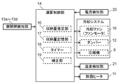
- FIG. 2 is a control block diagram of the refrigerator in the first embodiment of the present invention.
- FIG. 3A is a characteristic diagram of the air volume, static pressure, and rotational speed of the cooling fan of the refrigerator according to the first embodiment of the present invention.
- FIG. 3B is a characteristic diagram of the number of rotations and the storage amount of the cooling fan of the refrigerator according to the first embodiment of the present invention.
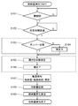
- FIG. 4 is a control flowchart of the refrigerator in the first embodiment of the present invention.
- FIG. 5A is a characteristic diagram of the air flow rate and the rotational speed of the cooling fan including the correction factor of the refrigerator in the first embodiment of the present invention.
- FIG. 5B is a characteristic diagram of the number of rotations of the cooling fan and the storage amount including the correction factor of the refrigerator according to the first embodiment of the present invention.
- FIG. 6 is a control block diagram of the refrigerator in the second embodiment of the present invention.
- FIG. 7A is a characteristic diagram of the air volume, static pressure, and input current of the cooling fan of the refrigerator in the second embodiment of the present invention.
- FIG. 7B is a characteristic diagram of an input current and a storage amount to a cooling fan of the refrigerator in the second embodiment of the present invention.
- FIG. 8 is a control flowchart of the refrigerator in the second embodiment of the present invention.
- FIG. 9A is a characteristic diagram of the air flow rate and input current of the cooling fan including the correction factor of the refrigerator in the second embodiment of the present invention.
- FIG. 9B is a characteristic diagram of the input current to the cooling fan and the storage capacity including the correction factor of the refrigerator in the second embodiment of the present invention.
- FIG. 10 is a control block diagram of the refrigerator in the third embodiment of the present invention.
- FIG. 11A is a characteristic diagram of the air volume and static pressure / rotation speed of the cooling fan of the refrigerator in the third embodiment of the present invention.
- FIG. 11B is a characteristic diagram of the number of rotations and the storage amount of the cooling fan of the refrigerator in the third embodiment of the present invention.
- FIG. 12 is a control flowchart of the refrigerator in the third embodiment of the present invention.
- FIG. 13 is sectional drawing of the refrigerator in the 4th Embodiment of this invention.
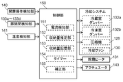
- FIG. 14 is a control block diagram of the refrigerator in the fourth embodiment of the present invention.
- FIG. 15 is a control flowchart of the operation for detecting the storage state of the refrigerator in the fourth embodiment of the present invention.
- FIG. 16 is a schematic diagram of the control behavior of the electrical load component when the refrigerator storage is loaded in the fourth embodiment of the present invention.
- FIG. 17: is a control flowchart of the operation
- FIG. 18 is a control flowchart of the operation of detecting the storage state of the refrigerator in the fifth embodiment of the present invention.
- FIG. 19 is a control flowchart of the operation for detecting the storage state of the refrigerator in the sixth embodiment of the present invention.
- FIG. 20 is a cross-sectional view of the refrigerator in the seventh embodiment of the present invention.
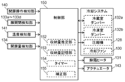
- FIG. 21 is a control block diagram of the refrigerator in the seventh embodiment of the present invention.
- FIG. 22 is a flowchart showing a control flow of an operation for detecting the storage state of the refrigerator in the seventh embodiment of the present invention.
- FIG. 23 is a characteristic diagram when detecting the storage state of the refrigerator in the seventh embodiment of the present invention.
- FIG. 24 is a flowchart showing a control flow of an operation of detecting the storage state of the vegetable room of the refrigerator in the seventh embodiment of the present invention.
- FIG. 25 is a characteristic diagram when detecting the storage state of the vegetable compartment of the refrigerator in the seventh embodiment of the present invention.
- FIG. 21 is a control block diagram of the refrigerator in the seventh embodiment of the present invention.
- FIG. 22 is a flowchart showing a control flow of an operation for detecting the storage state of the refrigerator in the seventh embodiment of the present invention.
- FIG. 23 is a characteristic diagram
- FIG. 26 is principal part sectional drawing which installed the electrostatic atomizer in the vegetable compartment of the refrigerator in the 8th Embodiment of this invention.
- FIG. 27 is a flowchart showing a control flow for operating the electrostatic atomizer of the refrigerator in the eighth embodiment of the present invention.
- FIG. 28 is a characteristic diagram showing the relationship between the discharge current and the humidity of the electrostatic atomizer of the refrigerator in the eighth embodiment of the present invention.
- FIG. 29 is a side sectional view of a refrigerator in the ninth embodiment of the present invention.
- FIG. 30 is a control block diagram of the refrigerator in the ninth embodiment of the present invention.
- FIG. 31 is a characteristic diagram of the air volume and static pressure / storage capacity of the cooling fan of the refrigerator in the ninth embodiment of the present invention.
- FIG. 32 is a control flowchart of the refrigerator in the ninth embodiment of the present invention.
- FIG. 33 is a characteristic diagram of the cooling fan air volume and storage capacity including the correction factor of the refrigerator according to the ninth embodiment of the present invention.
- FIG. 34 is a control block diagram of the refrigerator in the tenth embodiment of the present invention.
- FIG. 35 is a characteristic diagram of the air volume and static pressure / storage capacity of the cooling fan of the refrigerator in the tenth embodiment of the present invention.
- FIG. 36 is a control flowchart of the refrigerator in the tenth embodiment of the present invention.
- FIG. 37 is a side sectional view of the refrigerator in the eleventh embodiment of the present invention.
- FIG. 38A is a top cross-sectional view when the freezer compartment of the refrigerator according to the eleventh embodiment of the present invention is closed.
- FIG. 38B is a top cross-sectional view when the freezer compartment of the refrigerator according to the eleventh embodiment of the present invention is opened.
- FIG. 39 is a control block diagram of the refrigerator in the eleventh embodiment of the present invention.
- FIG. 40 is a storage capacity estimation characteristic diagram of the refrigerator in the eleventh embodiment of the present invention.
- FIG. 41 is a control flowchart of the refrigerator in the eleventh embodiment of the present invention.
- FIG. 42 is a control block diagram of the refrigerator in the twelfth embodiment of the present invention.
- FIG. 43 is a storage capacity estimation characteristic diagram of the refrigerator in the twelfth embodiment of the present invention.
- FIG. 44 is a control flowchart of the refrigerator in the twelfth embodiment of the present invention.
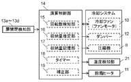
- FIG. 45 is a control block diagram of the refrigerator in the thirteenth embodiment of the present invention.
- FIG. 46 is a storage capacity estimation characteristic diagram of the refrigerator in the thirteenth embodiment of the present invention.
- FIG. 47 is a control flowchart of the refrigerator in the thirteenth embodiment of the present invention.
- FIG. 48 is a front perspective view of a refrigerator compartment of a conventional refrigerator.
- FIG. 1 is a side sectional view of a refrigerator according to the first embodiment of the present invention
- FIG. 2 is a control block diagram of the refrigerator according to the first embodiment of the present invention
- 3A is a characteristic diagram of the air volume and static pressure / rotation speed of the cooling fan of the refrigerator in the first embodiment of the present invention
- FIG. 3B is a cooling fan of the refrigerator in the first embodiment of the present invention
- FIG. 4 is a control flowchart of the refrigerator in the first embodiment of the present invention.
- FIG. 5A is a characteristic diagram of the air flow rate and the rotational speed of the cooling fan including the correction factor of the refrigerator in the first embodiment of the present invention
- FIG. 5B is the correction factor of the refrigerator in the first embodiment of the present invention. It is a characteristic view of the rotation speed of the cooling fan including the amount and the storage amount.
- the heat insulation box 1a of the refrigerator main body 1 has a structure having a heat insulating material in a space between an outer box mainly using a steel plate, an inner box formed of a resin such as ABS, and the outer box and the inner box.
- the interior of the refrigerator and the surroundings are insulated.
- the refrigerator main body 1 is partitioned into a plurality of storage rooms by partition walls 6a to 6c, and is provided with a refrigerating room 2 at the top, a switching room 3 below the refrigerating room 2, and a lower part of the switching room 3.
- a freezer compartment 4 is arranged, and a vegetable compartment 5 is arranged at the bottom.
- Insulation doors 7a to 7d are formed in the front opening of the refrigerator main body 1 so as to separate the outside air from the front of each storage room.
- a plurality of storage shelves 22 are provided in the refrigerator compartment 2. And a part of storage shelf 22 is comprised so that it can operate
- high-pressure components (not shown) of the refrigeration cycle such as the compressor 8 and a dryer for removing moisture are housed.
- a cooling chamber 1c for generating cold air is provided on the back of the freezer compartment 4, and in the cooling chamber 1c, the cooler 9 and the cool air generated by the cooler 9 are stored in the refrigerator compartment 2, the switching chamber 3, the freezer compartment 4, A cooling fan 10 for blowing air to the vegetable compartment 5 is arranged. Further, a defrost heater 11, a drain pan (not shown), a drain tube evaporating dish (not shown) and the like are configured to defrost frost and ice adhering to the cooler 9 and its surroundings.
- a temperature detection unit 21 is provided, and the temperature detection unit 21 plays the following role, for example.
- One is the role of correcting the influence on the rotational speed or the output current due to the ambient temperature of the cooling fan 10, and varies the voltage applied to the cooling fan 10 according to the ambient temperature detected by the temperature detector 21.
- the other is the role of detecting the frosting state on the cooler 9, and the temperature detection unit 21 detects frosting to prevent a decrease in heat exchange function or an increase in air path resistance due to frosting to some extent. .
- the matter relating to the main part of the invention described below is a type in which a compressor chamber 8 is arranged by providing a machine room in the rearmost region of the lowermost storage chamber of the conventional heat insulation box. It may be applied to other refrigerators.
- Refrigeration room 2 is normally set at 1 ° C to 5 ° C, with the lower limit being the temperature at which it is not frozen for refrigerated storage, and the lowermost vegetable room 5 is set at 2 ° C to 7 ° C, which is a temperature setting that is the same or slightly higher than that of refrigeration room 2.
- the freezer compartment 4 is set in a freezing temperature zone and is usually set at ⁇ 22 ° C. to ⁇ 15 ° C. for frozen storage, but in order to improve the frozen storage state, for example, ⁇ 30 ° C. or ⁇ It may be set at a low temperature of 25 ° C.
- Switching room 3 is refrigerated in addition to refrigerated storage set at 1 ° C to 5 ° C, vegetable storage set at 2 ° C to 7 ° C, and frozen storage usually set at -22 ° C to -15 ° C.
- the temperature can be switched to a preset temperature range between the temperature range and the freezing temperature range.
- the temperature of each storage room is adjusted by controlling the cooling system, that is, adjusting the motor rotation speed of the compressor 8, adjusting the rotation speed of the cooling fan 10, and adjusting the air volume distribution to each room by opening and closing the damper 12.
- the damper 12 is driven by a motor (not shown) to rotate and open / close the air passage, and the air passage is shielded / opened. It is possible to finely adjust the temperature. Normally, if the opening degree of the air passage is reduced, the air passage resistance increases, and the air volume by the cooling fan 10 decreases.
- the switching chamber 3 is a storage room including the temperature range of refrigeration and freezing.
- the refrigeration is performed in the refrigeration room 2 and the vegetable room 5, and the refrigeration is performed in the freezing room 4.
- a storage room specialized for switching only the intermediate temperature range of freezing may be used.
- the switching room 3 may be a storage room fixed to freezing in accordance with a recent increase in demand for frozen foods, for example, frozen foods.
- a configuration may be provided in which the switching chamber 3 and an ice making chamber for generating and storing ice are provided side by side.
- the cooling fan 10 has a built-in motor driver, and can be driven from the outside only by supplying a power supply voltage.
- the number of revolutions per unit time (hereinafter referred to as only the number of revolutions) can be commanded by analog input.
- it has a function of outputting the current number of rotations, and has a mechanism for outputting a voltage of a rectangular wave of one pulse every half rotation.
- the rotation speed is not stabilized by feedback with this function, only a constant voltage is applied, and the rotation speed fluctuates due to disturbance such as wind path resistance.
- the rotational speed tends to decrease with the decrease in the air volume. This is because the static pressure greatly increases due to the decrease in the air volume, and as a result, the load on the cooling fan 10 increases.
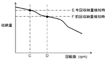
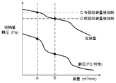
- the air volume of the cooling fan 10 varies depending on the increase / decrease of the air path resistance, that is, the storage amount of the refrigerator main body 1, the correlation between the rotation speed and the storage amount can be obtained as shown in FIG. 3B.
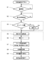
- the heat insulating doors 7a to 7d are opened and closed by the door open / close detection units 13a to 13d to determine whether food can be stored or taken out (step S1), and a predetermined time is counted by the timer 18 (step S2).
- the storage amount detection is started. This is because the cooling fan 10 is controlled to stop when any one of the heat insulating doors 7a to 7d is opened, and therefore the cooling fan 10 that is restarted immediately after the heat insulating doors 7a to 7d that have been opened is closed for a predetermined time. This is because the storage amount is detected after the operation is stabilized except in the transition period.
- step S3 it is determined whether or not the damper 12 is fully opened.
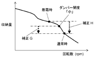
- the air volume may be reduced as shown in FIG. Therefore, the correction value G is reduced by the correction unit 19 as shown in FIG. 5B (step S4). Since the increase / decrease in the air volume depending on the open / close state of the damper 12 varies depending on the air path configuration, it is necessary to set a correction value for each system.
- the frost formation state on the cooler 9 is determined (step S5).
- the frost formation state is determined by a frost sensor, temperature detection in the vicinity of the cooler by the temperature detector 21, or an elapsed time immediately after defrosting by the defrost heater 11.
- the correction unit 19 decreases the correction value H as shown in FIG. 5B in order to discriminate the storage amount more as shown in FIG. (Step S6).
- the storage amount is estimated. From FIG. 3A, when the air volume is A, the rotation speed of the cooling fan 10 is output as C, and the storage amount estimation unit 16 of the calculation control unit 14 estimates the storage amount from FIG. 3B as E (step S7). . The estimated storage amount E is recorded in the storage amount storage unit 17 (step S8).
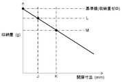
- the storage amount change is calculated. 3A, when the air volume is B, the rotation speed of the cooling fan 10 is output as D, and the storage amount estimation unit 16 of the arithmetic control unit 14 determines that the storage amount is F from FIG. It is estimated and recorded in the storage amount storage unit 17. Since the storage amount detected this time is E, the storage amount change is the difference between the storage amount F estimated last time and the storage amount E estimated this time (step S9).
- the subsequent cooling control is determined based on the storage amount estimated as described above or the storage amount change.
- the refrigerator in the present embodiment is a refrigerator compartment 2, a switching compartment 3, a freezer compartment 4, a vegetable compartment 5, and a storage compartment for cooling the compartment, which is partitioned by a heat insulation wall and a heat insulation door.
- a cooler 9 and a damper 12 for controlling the amount of cool air to the storage chamber are provided.
- the refrigerator in the present embodiment includes the heat insulating doors 7a to 7d that cover the storage room, the door open / close detection units 13a to 13d that detect opening and closing of the heat insulating doors 7a to 7d, and the cooling fan 10 that supplies cold air to the storage room.
- a rotation speed detection unit 15 that detects the rotation speed of the cooling fan 10 and a calculation control unit 14 that calculates the detection result.
- the fluctuation of the air path resistance due to the stored item is calculated from the rotation speed of the fan motor of the cooling fan 10 to estimate the stored amount.
- the temperature of the stored item is always kept in an optimum state, high freshness can be realized, and power consumption can be suppressed by preventing the stored item from being “too cold”.
- FIG. 6 is a control block diagram of the refrigerator in the second embodiment of the present invention
- FIG. 7A is a characteristic diagram of the air volume and static pressure / input current of the cooling fan of the refrigerator in the second embodiment of the present invention
- FIG. 7B is a characteristic diagram of an input current and a storage amount to a cooling fan of the refrigerator in the second embodiment of the present invention
- FIG. 8 is a control flowchart of the refrigerator in the second embodiment of the present invention
- FIG. 9A is a characteristic diagram of the air volume and input current of the cooling fan including the correction factor of the refrigerator in the second embodiment of the present invention.
- 9B is a characteristic diagram of the input current to the cooling fan and the storage amount including the correction factor of the refrigerator in the second embodiment of the present invention. Note that the same parts as those in the first embodiment of the present invention are denoted by the same reference numerals and description thereof is omitted.
- the cooling fan 10 has a built-in motor driver, and can be driven from the outside only by supplying a power supply voltage.
- the number of rotations of the cooling fan 10 per unit time (hereinafter referred to as only the number of rotations) can be commanded by analog input.
- it has a function of outputting the current number of rotations, and has a mechanism for outputting a voltage of a rectangular wave of one pulse every half rotation.
- the rotational speed is made constant by feedback with this function, and the input current to the fan is likely to fluctuate due to disturbance such as air path resistance.
- the input current tends to increase with the decrease in the air volume. This is because the static pressure greatly increases due to the decrease in the air volume, and as a result, the load on the cooling fan 10 increases.
- the air volume of the cooling fan 10 varies depending on the increase / decrease of the air path resistance, that is, the storage capacity of the refrigerator body 1, the correlation between the input current and the storage capacity can be obtained as shown in FIG. 7B.
- the door open / close detectors 13a to 13d open / close any of the heat insulating doors 7a to 7d in the storage room to determine whether food can be stored or taken out (step S11).
- the storage amount detection is started after measuring (step S12). This is because the cooling fan 10 is controlled to stop when any one of the heat insulating doors 7a to 7d is opened, and therefore the cooling fan 10 that is restarted immediately after the heat insulating doors 7a to 7d that have been opened is closed for a predetermined time. This is because the storage amount is detected after the operation is stabilized except in the transition period.
- step S13 it is determined whether or not the damper 12 is fully open.
- the input current increases as shown in FIG. Therefore, the correction value R is reduced by the correction unit 19 as shown in FIG. 9B (step S14). Since the increase / decrease in the air volume depending on the open / close state of the damper 12 varies depending on the air path configuration, it is necessary to set a correction value for each system.
- the frosting state on the cooler 9 is determined (step S15).
- the frosting state is determined by a frosting sensor (not shown), temperature detection in the vicinity of the cooler by the temperature detection unit 21, or an elapsed time immediately after defrosting by the defrosting heater 11.
- the correction value 19 is reduced by the correction unit 19 as shown in FIG. 9B in order to discriminate the storage amount by increasing the input current as shown in FIG. (Step S16).
- the input current of the cooling fan 10 is performed by a current detector 20 such as a current transformer or a shunt method.
- a current detector 20 such as a current transformer or a shunt method.
- the input current to the motor is not a direct current, it is handled with a peak value, an effective value, or a value smoothed by a capacitor.
- the storage amount estimation unit 16 of the calculation control unit 14 estimates the storage amount from FIG. 7B as N (step S17).
- the estimated storage amount N is recorded in the storage amount storage unit 17 (step S18).
- the storage amount change is calculated. 7A, when the air volume is K at the previous storage amount detection, the input current of the cooling fan 10 becomes M, and the storage amount estimation unit 16 of the calculation control unit 14 estimates the storage amount as O from FIG. 7B. And stored in the storage amount storage unit 17. Since the storage amount detected this time is N, the storage amount change is the difference between the storage amount O estimated last time and the storage amount N estimated this time (step S19).
- the subsequent cooling control is determined based on the storage amount estimated as described above or the storage amount change.
- the refrigerator according to the present embodiment includes the door open / close detectors 13a to 13d that detect opening and closing of the heat insulating doors 7a to 7d, the cooling fan 10 that supplies cool air to the storage chamber, and the input current of the cooling fan 10
- a current detection unit 20 that detects a value and a calculation control unit 14 that calculates the detection result are provided.
- the refrigerator in this Embodiment calculates the fluctuation
- the refrigerator in the present embodiment can quickly and appropriately control the cooling capacity, and the temperature of the stored item is always kept in an optimum state, and high freshness can be realized. .
- power consumption can be suppressed by preventing the stored item from being “too cold”.
- FIG. 10 is a control block diagram of the refrigerator in the embodiment of the present invention
- FIG. 11A is a characteristic diagram of the air volume and static pressure / rotation speed of the cooling fan of the refrigerator in the third embodiment of the present invention
- FIG. 10 is a characteristic diagram of the number of rotations and the storage amount of the cooling fan of the refrigerator in the third embodiment of the present invention
- FIG. 12 is a control flowchart of the refrigerator in the third embodiment of the present invention.
- the same parts as those in the first embodiment or the second embodiment are denoted by the same reference numerals and description thereof is omitted.
- the refrigerator according to the third embodiment of the present invention configured as described above is characterized in that there is no correction step (from step S3 to step S6) in the first embodiment.
- the explanation will focus on the function of estimating the change in quantity.
- the configuration of the cooling fan 10 is the same as that of the first embodiment, and detailed description thereof is omitted.
- the amount of storage is estimated based on the number of rotations of the cooling fan 10 every predetermined time even if the heat insulating doors 7a to 7d in the storage room are not opened or closed by counting by the timer 18 (step S21). (Step S22).
- the storage amount estimated here is recorded in the storage amount storage unit 17 (step S23), and further, conditions that may cause an error in storage amount detection, such as the operating state of the compressor 8 at the time of detection and the open / close state of the damper 12, are detected. It records in the condition memory
- storage part 23 At this time, from FIG. 11A, when the air flow rate of the cooling fan 10 is U, the rotation speed of the cooling fan 10 is output as W, and the storage amount estimation unit 16 of the arithmetic control unit 14 sets the storage amount from FIG. It is estimated that.
- the yield change is estimated by comparing with the amount of storage detected after food storage.
- the timer 18 measures a predetermined time (step S25).
- the storage amount detection is started. This is because the cooling fan 10 is controlled to stop when any one of the heat insulating doors 7a to 7d in the storage room is opened. By removing the transition period of the cooling fan 10 that is restarted immediately after the opened heat insulating doors 7a to 7d are closed, the storage amount can be detected after the operation of the cooling fan 10 is stabilized.
- step S24 the operation state of the compressor 8 and the open / close state of the damper 12 recorded in the detection condition storage unit 23 in step S24 are read, and the operation of the refrigerator is adjusted to the same conditions (step S24). S27).
- changes in airway resistance caused by factors other than food storage are equivalent to those at the time of storage amount detection immediately before food is added.
- the time interval for detecting the storage amount before and after food storage is relatively short, the frosting state on the cooler 9 is almost the same as before food storage.
- the storage amount is estimated. From FIG. 11A, when the air volume is T, the rotation speed of the cooling fan 10 is output as V, and the storage amount estimation unit 16 of the calculation control unit 14 estimates the storage amount from FIG. 11B as X (step S28). . Then, the estimated storage amount X is recorded in the storage amount storage unit 17 (step S29).
- the storage amount change is calculated. Since the storage amount immediately before food storage is recorded as Y and the storage amount detected after storage is X, the storage amount change is the difference between X and Y (step S30).
- the subsequent cooling control is determined from the storage amount change estimated as described above.
- the optimum cooling control according to the situation is selected, such as performing a rapid cooling operation by controlling the cooling system.
- the refrigerator according to the present embodiment includes the door open / close detectors 13a to 13d that detect opening and closing of the heat insulating doors 7a to 7d, the cooling fan 10 that supplies cool air to the storage chamber, and the number of rotations of the cooling fan 10 And a calculation control unit 14 for calculating the detection result.
- the refrigerator in the present embodiment is capable of optimal temperature management in accordance with the storage of food by calculating the fluctuation of the air path resistance due to the stored item from the rotation speed of the fan motor and estimating the change in the storage amount. Thus, high freshness can be realized.
- the storage amount change detection using the rotation speed of the cooling fan 10 has been described.
- the storage amount change detection by the input current can also be performed as in the second embodiment.
- the storage amount and the fan in FIGS. 3B and 7B are described. It is of course possible to predict the absolute storage amount at the estimated time using correlation data with the motor rotation speed or current value.
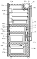
- FIG. 13 is a cross-sectional view of a refrigerator in the fourth embodiment of the present invention
- FIG. 14 is a control block diagram of the refrigerator in the fourth embodiment of the present invention
- FIG. 15 is a diagram of the fourth embodiment of the present invention. It is a control flowchart of the operation
- FIG. 16 is a schematic view of the control behavior of the electrical load component when the refrigerator storage according to the fourth embodiment of the present invention is charged
- FIG. 17 is a diagram of the refrigerator of the fourth embodiment of the present invention. It is a control flowchart of the operation
- the heat insulating box 31 a of the refrigerator main body 31 has a heat insulating material in an outer box mainly using a steel plate, an inner box formed of a resin such as ABS, and a space between the outer box and the inner box. With the provided structure, it is insulated from the surroundings.
- the refrigerator main body 31 is thermally partitioned into a plurality of storage chambers by partition walls 36a to 36c, a refrigeration chamber 32 is provided at the top, and a switching chamber 33 is provided below the refrigeration chamber 32.
- a freezing room 34 is provided in the lower part of the switching room 33, and a vegetable room 35 is arranged in the lowermost part.
- Insulation doors 37a to 37d are provided in front opening portions of the refrigerator main body 31 so as to be openable and closable in order to partition the front of each storage room from the outside air.
- a plurality of storage shelves 52 are provided in the refrigerator compartment 32, and some of the storage shelves 52 are configured to be movable up and down.
- high-pressure components of the refrigeration cycle such as the compressor 38 and a dryer for removing moisture are housed.
- a cooling chamber 31c that generates cold air is provided on the back surface of the freezer compartment 34. Inside the cooling chamber 31c, the cooler 40 and the cold air are blown to the refrigerator compartment 32, the switching chamber 33, the freezer compartment 34, and the vegetable compartment 35.
- a cooling fan 41 is disposed. Further, a defrost heater 44, a drain pan (not shown), a drain tube evaporating dish (not shown) and the like are provided to defrost frost and ice adhering to the cooler 40 and its surroundings.
- a temperature detection unit 47 which plays the following role, for example. One is to correct the influence of the ambient temperature of the cooling fan 41 on the rotation speed of the cooling fan 41 or the influence on the output current.
- the temperature detection unit 47 is used by changing the applied voltage according to the ambient temperature. To do.
- one is a role which detects the frost formation state to the cooler 40, and is used in order to detect the fall of the heat exchange property by frost formation, or the increase in air path resistance.
- the matters relating to the main part of the invention described below are of the type in which a compressor room is provided by providing a machine room in the rearmost region of the lowermost storage room of a conventional heat insulation box. You may apply to a refrigerator.
- the refrigerator compartment 32 is normally set to 1 ° C. to 5 ° C. at the lower limit of the temperature at which it is not frozen for refrigerated storage, and the lowermost vegetable compartment 35 is set to 2 ° C. to 7 ° C., which is a temperature setting that is equal to or slightly higher than that of the refrigerator compartment 32.
- the freezer compartment 34 is set in a freezing temperature zone, and is usually set at ⁇ 22 ° C. to ⁇ 15 ° C. for frozen storage. However, in order to improve the frozen storage state, for example, ⁇ 30 ° C. or ⁇ It may be set at a low temperature of 25 ° C.
- the switching chamber 33 is refrigerated in addition to refrigerated storage set at 1 ° C to 5 ° C, vegetable storage set at 2 ° C to 7 ° C, and frozen storage usually set at -22 ° C to -15 ° C.
- the temperature can be switched to a preset temperature range between the temperature range and the freezing temperature range.
- the temperature of each room is controlled by controlling the cooling system, that is, adjusting the motor rotation speed of the compressor 38, adjusting the rotation speed of the cooling fan 41, and adjusting the air volume distribution to each room by opening and closing the damper 42.
- the damper 42 is a motor that drives a rotary opening / closing part to shield and open the air passage.
- the opening / closing part is opened halfway to share a breeze in the storage room, etc., and fine temperature control is performed by adjusting the opening. It is possible. Normally, if the opening is reduced, the air path resistance increases, and the air volume by the cooling fan 41 decreases.
- the switching chamber 33 is a storage room including the temperature range of refrigeration and freezing.
- the refrigeration is performed by the refrigeration room 32 and the vegetable room 35
- the freezing is performed by the freezing room 34.
- a storage room specialized for switching only the intermediate temperature range of freezing may be used.
- the storage room fixed to freezing may be sufficient as the demand for frozen foods has increased in recent years, for example, frozen food.
- a configuration may be provided in which a switching chamber 33 and an ice making chamber for generating and storing ice are provided side by side.
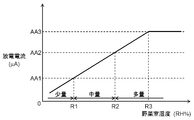
- the input of the compressor 38 that is, the input of the motor for operating the compression element in the compressor 38 varies greatly depending on the evaporation temperature of the refrigerant in the cooler 40. For example, when newly stored items are put in the refrigerator, the air warmed by the stored items flows into the cooler 40, the evaporation temperature rises, and the refrigerant circulation rate in the cooling system increases. The input of the compressor 38 becomes large. That is, it is possible to estimate the change in the storage amount from the change in the compressor 38 input.
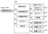
- detection of an opening operation or closing operation by the door open / close detection units 43a to 43d is used as a trigger, an input value to the compressor 38 is detected by the detection unit 46 and the temperature detection unit 47, and calculation control is performed from the signal.
- the storage amount is estimated in the part 48. Then, based on the obtained results, the start determination of the power saving / rapid cooling operation is performed, and the operations of the compressor 38, the cooling fan 41, the damper 42, the defrosting heater 44, and the temperature compensation / condensation prevention heater 45 related to the cooling operation are determined. To do.
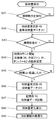
- the door opening / closing detectors 43a to 43d open the heat insulating doors 37a to 37d to determine the possibility of food storage or removal (step S41). Then, from the input value of the compressor 38 calculated from the detection unit 46 by the storage amount estimation unit 49, the storage amount at that time is estimated as the reference storage amount data A1 (step S42). At this time, it is preferable to estimate the storage amount within one second after detecting the opening operation of the heat insulating doors 37a to 37d. This is because the cooling fan 41 stops and the input of the compressor 38 changes when a long time has elapsed after detecting the opening operation of the heat insulating doors 37a to 37d.
- step S43 when it is confirmed that the heat insulating doors 7a to 7d are closed (step S43), the operations of the compressor 38, the cooling fan 41, and the damper 42 are fixed (step S44). This is to eliminate disturbance factors such as a change in the rotation speed of the compressor 38, a change in the rotation speed of the cooling fan 41, a temperature change around the cooler 40 due to the opening / closing operation of the damper 42, and a change in the air volume.
- the storage amount estimation unit 49 estimates the storage amount from the compressor 38 input value calculated from the detection unit 46 (step S46), and the determined storage amount data is recorded in the storage unit 50 (step S46). S47). Then, the storage amount change is calculated from the difference between the reference storage amount data A1 and the storage amount data B1 (step S48), and the optimum cooling operation is performed based on the storage amount change (step S49).
- the power saving operation is performed by controlling the rotational speed of the compressor 38, the rotational speed of the cooling fan 41, or reducing the opening of the damper 42.
- the rapid cooling operation is performed by control such as increasing the rotational speed of the compressor 38, increasing the rotational speed of the cooling fan 41, or increasing the opening degree of the damper 42.
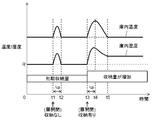
- FIG. 16 shows a schematic diagram of the control behavior of the electrical load component when the refrigerator is loaded.
- the cooling operation is performed based on the detection result of the internal atmosphere temperature by the temperature sensor, it takes time until the temperature sensor detects an increase in the internal temperature after the stored item is inserted.
- the storage amount is estimated from the input value of the compressor 38, and the cooling operation is performed based on the estimation result of the storage amount. Therefore, when the increase in the storage amount is detected, the rapid cooling operation is performed.
- the power saving operation is performed, so that the stored item is prevented from being too cold and the power consumption can be reduced.
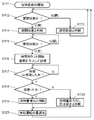
- the door opening / closing detectors 43a to 43d open the heat insulating doors 37a to 37d to store food, or The possibility of removal is determined (step S52), and the reference storage amount data A2 is read from the storage unit 50 (step S53).
- the reference storage amount data A2 is calculated from the storage amount data immediately before the compressor 38 stops, for example, by the storage unit 50 periodically detecting and learning the input of the compressor 38 at regular time intervals (for example, 5 minutes). It is good to do. Or you may calculate from the average value of the storage amount data of the past fixed period (for example, one week) recorded by the memory
- Step S54 it is confirmed that the heat insulating doors 37a to 37d are closed (step S54), and when the compressor 38 is restarted (step S55), the operations of the compressor 38, the cooling fan 41, and the damper 42 are fixed. (Step S56).
- step S57 estimation of the storage amount is started.
- the storage amount estimation unit 49 estimates the storage amount from the compressor 38 input value calculated from the detection unit 46 (step S58), and the determined storage amount data is recorded in the storage unit 50 (step S58). S59). Then, the storage amount change is calculated from the difference between the reference storage amount data A2 and the storage amount data B2 (step S60), and the optimum cooling operation is performed based on the storage amount change (step S61).
- the storage unit 50 periodically detects and learns the input of the compressor 38 at regular time intervals (for example, 5 minutes), and the defrosting stores the reference storage amount data A2. It is better to calculate from the storage amount data immediately before starting. Or you may calculate from the average value of the storage amount data of the past fixed period (for example, one week) recorded by the memory
- the estimation accuracy in the storage amount estimation unit 49 can be improved by having a relationship of predetermined time ⁇ s ⁇ predetermined time ⁇ t ⁇ predetermined time ⁇ u.
- the refrigerator according to the present embodiment includes the door opening / closing detection units 43a to 43d that detect opening and closing of the heat insulating doors 37a to 37d, the detection unit 46 that detects input to the compressor 38, and the detection unit 46.
- An arithmetic control unit 48 for arithmetically processing the detection result is provided.
- the arithmetic control unit 48 estimates the storage amount of the storage room based on the detection results of the door opening / closing detection units 43a to 43d and the detection result of the detection unit 46, thereby achieving high freshness. And optimal cooling operation that achieves both energy savings.
- FIG. 18 shows a control flowchart of the operation for detecting the storage state of the refrigerator in the present embodiment.
- the heat insulating doors 37a to 37d are opened by the door open / close detection units 43a to 43d, and the possibility of storing or taking out food is determined (step S71).
- the operating state of the refrigerator and the attachment of the cooler 40 are determined.
- the frost state is determined (step S72).
- the operating state of the refrigerator is determined by the rotation speed of the compressor 38, the rotation speed of the cooling fan 41, and the opening degree of the damper 42, and the correction unit 51 calculates the correction G.
- the frosting state of the cooler 40 is determined by the frosting sensor, the temperature detection in the vicinity of the cooler 40 by the temperature detection unit 47, or the elapsed time immediately after the defrosting by the defrosting heater 44, and is corrected by the correction unit 51. Is calculated.
- the storage amount estimation unit 49 estimates the storage amount as the storage amount data C from the value obtained by adding the correction value G and the correction value H to the compressor 38 input value calculated from the detection unit 46 (step S73). For example, when determining the operation state of the refrigerator, if the rotation speed of the compressor 38 is high or the rotation speed of the cooling fan 41 is high, the input of the compressor 38 increases, and the correction value G is decreased. Further, for example, in the determination of the frosting state of the cooler 40, when the amount of frosting on the cooler 40 is large, the heat exchange amount in the cooler 40 decreases and the input of the compressor 38 becomes small. The correction value H is added.
- step S74 when it is confirmed that the heat insulating doors 37a to 37d are closed (step S74), the operations of the compressor 38, the cooling fan 41, and the damper 42 are fixed (step S75). This is to eliminate disturbance factors such as a change in the rotation speed of the compressor 38, a change in the rotation speed of the cooling fan 41, a temperature change around the cooler 40 due to the opening / closing operation of the damper 42, and a change in the air volume.
- step S76 the storage amount estimation is started. This is because the cooling fan 41 is controlled to stop when the heat insulating doors 37a to 37d are opened. By removing the transition period of the cooling fan 41 that restarts immediately after the heat insulating doors 37a to 37d are closed, the storage amount is detected after the operation of the cooling fan 41 is stabilized.
- the storage amount estimation unit 49 estimates the storage amount as the storage amount data D from the value obtained by adding the correction value G and the correction value H to the input value of the compressor 38 calculated from the detection unit 46 (step S78).
- the stored amount data is recorded in the storage unit 50 (step S79).
- the storage amount change is calculated from the difference between the reference storage amount data C and the storage amount data D (step S80), and the optimum cooling operation is performed based on the storage amount change (step S81).
- the storage unit 50 periodically detects and learns the input of the compressor 38 at regular time intervals (for example, 5 minutes), and stores the reference storage amount data.
- C1 (not shown) may be calculated from the storage amount data immediately before the compressor 38 stops. Or you may calculate from the average value of the storage amount data of the past fixed period (for example, one week) recorded by the memory
- FIG. After a predetermined time ⁇ t (not shown) has elapsed since the compressor 38 was restarted, it is preferable to start the estimation of the storage amount and calculate the storage amount change from the difference from the reference data.
- the storage unit 50 periodically detects and learns the input of the compressor 38 at regular time intervals (for example, 5 minutes), and the defrosting stores the reference storage amount data C1. It is better to calculate from the storage amount data immediately before starting. Or you may calculate from the average value of the storage amount data of the past fixed period (for example, one week) recorded by the memory
- FIG. 19 shows a control flowchart of the operation for detecting the storage state of the refrigerator in the sixth embodiment of the present invention.
- any of the heat insulating doors 37a to 37d is opened by the door open / close detection units 43a to 43d to determine whether food can be stored or taken out (step S91), and the reference storage amount data E is stored from the storage unit 50.
- Read step S92).
- the reference storage amount data E is calculated from the storage amount data immediately before the door is opened and closed by periodically detecting and learning the input of the compressor 38 at regular intervals (for example, 5 minutes) by the storage unit 50, for example. It is good. Or you may calculate from the average value of the storage amount data of the past fixed period (for example, one week) recorded by the memory
- step S93 when it is confirmed that the heat insulating doors 37a to 37d are closed (step S93), the operations of the compressor 38, the cooling fan 41, and the damper 42 are fixed (step S94). This is to eliminate disturbance factors such as a change in the rotation speed of the compressor 38, a change in the rotation speed of the cooling fan 41, a temperature change around the cooler 40 due to the opening / closing operation of the damper 42, and a change in the air volume.
- step S95 estimation of the storage amount is started. This is because the cooling fan 41 is controlled to stop when the heat insulating doors 37a to 37d are opened. By removing the transition period of the cooling fan 41 that restarts immediately after the heat insulating doors 37a to 37d are closed, the storage amount is detected after the operation of the cooling fan 41 is stabilized.
- the correction unit 51 calculates the correction value K and the correction value L (step S96).
- the storage amount estimation unit 49 estimates the storage amount as storage amount data F from the value obtained by adding the correction value K and the correction value L to the compressor 38 input value calculated from the detection unit 46 (step S97), and the determination.
- the stored amount data is recorded in the storage unit 50 (step S98).
- the storage amount change is calculated from the difference between the reference storage amount data E and the storage amount data F (step S99), and the optimum cooling operation is performed based on the storage amount change (step S100).
- the storage unit 50 periodically detects and learns the input of the compressor 38 at regular time intervals (for example, 5 minutes), and stores the reference storage amount data. It is preferable to calculate E1 (not shown) from the storage amount data immediately before the compressor 38 stops. Or you may calculate from the average value of the storage amount data of the past fixed period (for example, one week) recorded by the memory
- the storage unit 50 periodically detects and learns the input of the compressor 38 at regular time intervals (for example, 5 minutes), and stores the reference storage amount data E1 (not shown). It is better to calculate from the storage amount data immediately before the defrost starts. Or you may calculate from the average value of the storage amount data of the past fixed period (for example, one week) recorded by the memory
- the storage amount is estimated from the input value to the compressor 38.
- the storage amount may be estimated from the current value of the compressor 38.
- FIG. 20 is a sectional view of a refrigerator according to the seventh embodiment of the present invention
- FIG. 21 is a control block diagram of the refrigerator according to the seventh embodiment of the present invention
- FIG. 22 is a seventh embodiment of the present invention. It is a flowchart which shows the control flow of the operation
- FIG. 23 is a characteristic diagram when detecting the storage state of the refrigerator according to the seventh embodiment of the present invention
- FIG. 24 detects the storage state of the vegetable compartment of the refrigerator according to the seventh embodiment of the present invention.
- FIG. 25 is a characteristic diagram when detecting the storage state of the vegetable compartment of the refrigerator in the seventh embodiment of the present invention.
- the refrigerator main body 61 has a heat insulating box 61a in which a heat insulating material such as urethane is foam-filled.
- a refrigeration chamber 62 is provided at the top of the refrigerator body 61, and a switching chamber 63 and an ice making chamber (not shown) provided in parallel to the switching chamber 63 are provided below the refrigeration chamber 62. Yes.
- a vegetable room 65 is provided in the lower part of the refrigerator body 61, and a freezing room 64 is provided between the switching room 63 and the ice making room installed in parallel and the vegetable room 65.
- the refrigerator compartment 62, the switching chamber 63, and the ice making chamber are partitioned by a partition wall 66a having heat insulation properties, and the switching chamber 63, the ice making chamber, and the freezing chamber 64 are partitioned by a partition wall 66b.
- 65 is partitioned by a partition wall 66c.
- heat insulating doors 67a to 67d in which a heat insulating material such as urethane is foamed and filled are provided at the opening of each storage chamber.
- the refrigerator compartment 62 is closed by a heat insulating door 67a so as to be freely opened and closed, and the switching chamber 63 is closed by a heat insulating door 67b so as to be freely opened and closed.
- the freezer compartment 64 is closed by a heat insulating door 67c so that it can be opened and closed, and the vegetable compartment 65 is closed by a heat insulating door 67d so that it can be opened and closed.
- the heat insulating door 67a of the refrigerator compartment 62 at the uppermost stage is a double door type, and the other heat insulating doors 67b to 67d are a pull-out type.
- door open / close detection units 73a to 73d for detecting the open / closed state of the heat insulating doors 67a to 67d are provided between the heat insulating doors 67a to 67d and the heat insulating box 61a.
- Specific devices for the door open / close detection units 73a to 73d include a method using a Hall IC, MR element, reed switch, etc. and a magnet, and a method using a mechanical contact such as a push switch.
- a humidity detector 74a for detecting the humidity in the room is fixed, and in the vegetable compartment 65, a humidity detector 74b is fixed at an arbitrary place. Since the humidity cannot be detected in the freezing temperature zone, it is not installed in the freezing room 64 or the freezing setting switching room 63.
- the humidity detectors 74a to 74b resistance type or capacitive type humidity sensors may be used.
- the humidity detectors 74a to 74b are attached to a place where the sensor unit is not condensed.
- the top surface portion of the heat insulating box 61a has a machine room 61b provided with a stepped recess toward the back of the refrigerator, and includes a compressor 68, a dryer (not shown) for removing moisture, and a condenser (not shown). And a heat radiating pipe (not shown) for radiating heat.
- a compressor 68 as a base point, a refrigerant is sealed in a refrigeration cycle in which a capillary tube 69 and a cooler 70 are sequentially connected in an annular manner, and a cooling operation is performed.
- a flammable refrigerant is often used as a refrigerant for environmental protection.
- these functional parts can be arranged in the machine room.
- the cooler 70 is in the cooler chamber 61c at the back of the freezer compartment 64.
- a cooler fan 71 is disposed above the cooler 70, and the cooler air is generated by the cooler 70 in each storage chamber.
- the damper 72 is installed in the cooling chamber 61 c near the refrigerator compartment 62, and the air passage opening is adjusted so that the very cold cold air in the freezing temperature zone generated by the cooler 70 does not flow directly into the refrigerator compartment 62. And optimal air flow control.
- the refrigerator compartment 62 is normally 1 ° C to 5 ° C with the temperature not frozen for refrigerated storage, and the refrigerator compartment 4 is usually -22 ° C to -18 ° C (to improve the frozen storage condition)
- the vegetable room 65 is set to a temperature setting of 2 ° C. to 7 ° C., which is the same as or slightly higher than that of the refrigerator room 62.
- the switching chamber 63 may be set to a freezing to refrigeration temperature range, and may be set to a fine temperature setting such as partial, chilled, or ice temperature, or in recent years when frozen foods are frequently used. good.
- the open / closed states of the heat insulating doors 67a to 67d detected by the door open / close detection units 73a to 73d are input to the arithmetic control unit 75 as a signal SG1. Further, the humidity in the storage chamber detected by the humidity detection units 74a to 74b is input to the calculation control unit 75 as a signal SG2, and the storage amount is calculated and estimated from the signals SG1 and SG2.
- step S111 When the storage amount detection is started in step S111, the open / closed states of the heat insulating doors 67a to 67d of the refrigerator compartment 62 are detected by the door open / close detection units 73a to 73d in step S112. If the heat insulating doors 67a to 67d are closed, it is determined in step S113 that the heat insulating doors 67a to 67d are closed, the signal SG1 is output from the door open / close detection units 73a to 73d to the arithmetic control unit 75, and the logic is returned to step SG2.
- step S114 determines that the door is open, and the signal SG1 is output from the door open / close detection units 73a to 73d to the arithmetic control unit 75.
- the logic moves to step S115.
- step S115 the door open / close detectors 73a to 73d again detect the open / closed state of the heat insulating doors 67a to 67d of the refrigerator compartment 62. If any of the heat insulating doors 67a to 67d is open, the door open / close detection units 73a to 73d are closed. repeat.
- step S116 When it is detected that the heat insulating doors 67a to 67d are closed, the signal SG1 is input to the arithmetic control unit 75, and the logic advances to step S116. That is, between steps S112 to S115, it is estimated that there is a possibility that the stored items are stored in the refrigerator compartment 62 because the door is opened and closed.
- step S116 time counting is started, and the humidity detectors 74a and 74b detect the humidity in the refrigerator compartment 62, input it as a signal SG2 to the arithmetic control unit 75, store the humidity as R, and store the logic.
- the process proceeds to step S117.
- the time point of step S116 corresponds to time t1 (when storage is not performed) or time t3 (when storage is performed) shown in the characteristic diagram of FIG. Note that if the functional components for cooling control are operating at the humidity detection measurement timing, the temperature and humidity fluctuations in the cabinet are large, and specifically, the damper 72 is closed (the air volume is sent to the refrigerator compartment 62).
- the cooling fan 71 is stopped (cool air is not circulated), or the compressor 68 is stopped (the internal temperature is not changed). Furthermore, if measurement is performed after a predetermined time has elapsed from the stop state of the functional component, the temperature and humidity are stable and accurate detection can be performed. In the following description, the humidity detection measurement timing is performed by stopping the functional components in the same manner as described above.
- step S117 it is determined whether or not a predetermined period ⁇ a that has been determined in advance has elapsed. If not, step S117 is repeated until the time ⁇ a elapses, and the time ⁇ a If so, the logic advances to step S118.
- the predetermined period ⁇ a is such that the temperature and humidity once increased due to the influence of outside air flow when the stored items are put into the refrigerator compartment 62 just by opening and closing the heat insulating doors 67a to 67d. It is sufficient to set a time for returning to the numerical value before opening and closing 67a to 67d.
- step S118 the humidity in the refrigerator compartment 62 is detected again by the humidity detector 74a at the time t2 (when the storage is not performed) or the time t4 (when the storage is performed) shown in the characteristic diagram of FIG.
- the signal SG2 is input to the arithmetic control unit 75 and compared with the humidity R stored in step S116. If the humidity is higher than R, the logic advances to step S119 to determine that the storage amount has increased, otherwise the logic advances to step S120 to determine that the storage amount has decreased or not changed.
- the change in humidity in the characteristic diagram of FIG. 23 is shown schematically, and actually, the cold air dehumidified by the cooler 70 flows into the refrigerator compartment 62 with the damper 72 open.
- the humidity detected by the humidity detector 74a gradually decreases, and when the damper 72 is closed after being cooled to a predetermined temperature, the humidity detected by the humidity detector 74a is repeatedly increased. It represents the average humidity.
- step S121 for example, when the storage capacity increases, the capacity of the compressor 68 and the cooling fan 71 is increased to perform a rapid cooling operation, or when the storage capacity does not change or decreases, the current operation is maintained and the capacity is decreased. Optimum operation of the refrigeration cycle, such as switching to the saved power saving operation.
- the humidity change in the characteristic diagram of FIG. 25 is also a schematic representation of the average humidity, similar to the humidity change of the characteristic diagram of FIG.
- the door open / close detection unit 73d detects the open / close state of the heat insulating door 67d of the vegetable compartment 65 in step S132. If the heat insulating door 67d is closed, it is determined in step S133 that the heat insulating door 67d is closed, the signal SG1 is output from the door opening / closing detection unit 73d to the arithmetic control unit 75, and the logic is returned to step S132.
- step S132 the logic advances to step S134 to determine that it is in the open state, and the signal SG1 from the door open / close detection unit 73d is output to the arithmetic control unit 75, and the logic is set to step S135.
- step S135 the door open / close detection unit 73d detects the open / close state of the heat insulating door 67d of the vegetable compartment 65 again. If the heat insulating door 67d is open, step S135 is repeated.
- the signal SG1 is input to the arithmetic control unit 75, and the logic advances to step S136. That is, it is estimated that there is a possibility that the stored items (vegetables) are stored in the vegetable compartment 65 due to the door opening / closing between step S132 and step S135.
- step S136 time counting is started, and the humidity detector 74b detects the humidity of the vegetable compartment 65, inputs it as a signal SG2 to the arithmetic control unit 75, stores the humidity as R0, and stores the logic in step S137. Proceed to The time point of step S136 corresponds to time t6 (when storage is not performed) or time t8 (when storage is performed) shown in the characteristic diagram of FIG.
- step S137 it is determined whether or not a predetermined period ⁇ a that has been determined in advance has elapsed. If not, step S137 is repeated until the time ⁇ a has elapsed, and the time ⁇ a If so, the logic advances to step S138. In addition, what is necessary is just to set the time of this predetermined period (DELTA) a similarly to the case of the refrigerator compartment 62 mentioned above.
- DELTA this predetermined period
- step S138 the humidity in the vegetable compartment 65 is detected again by the humidity detection unit 74b at the time t7 (when storage is not performed) or the time t9 (when storage is performed) shown in the characteristic diagram of FIG.
- the signal SG2 is input to the arithmetic control unit 75 and compared with the humidity R0 stored in step S136. If the humidity is higher than R0, the logic advances to step S139, and it is determined that the storage amount has increased, and counting of time is started. Otherwise, the logic advances to step S140, and the storage amount does not change. However, it is judged that it decreased.
- step S141 it is determined whether or not a predetermined period ⁇ b that has been determined in advance has elapsed. If not, step S141 is repeated until the time ⁇ b has elapsed, and the time ⁇ b has elapsed. Then, the logic advances to step S142 (time t9 in FIG. 25). In addition, as the time of this predetermined period ⁇ b, the time for estimating that the temperature and humidity in the storage are once stabilized (at time t10 in FIG. 25) and the water evaporation from the stored items (vegetables) is in equilibrium is set in advance. It is to set.
- step S142 the humidity of the vegetable compartment 65 is detected by the humidity detector 74b, input to the calculation controller 75 as a signal SG2, and compared with the humidity R0 stored in step S136. Specifically, compared with the humidity R1, R2, and R3 determined in advance from the amount of water evaporated according to the storage amount, the storage amount is small if R0 ⁇ humidity ⁇ R1 in step S143, R1 ⁇ humidity If ⁇ R2, the storage amount is medium, and if R2 ⁇ humidity ⁇ R3, the storage amount is determined to be large.
- step S144 for example, when the storage amount is large, the compressor 8 and the cooling fan 71 are increased in capacity to perform a strong cooling operation, when the storage amount is medium, the normal operation is performed, and when the storage amount is small, the cooling operation is performed. Optimize the refrigeration cycle so that
- the door opening / closing detection unit 73a that detects the opening / closing of the heat insulating door 67a of the refrigerator compartment 62
- the humidity detector 74a that detects the humidity of the refrigerator compartment 62
- the humidity detector 74a that detects the humidity of the refrigerator compartment 62
- an arithmetic control unit 75 for arithmetically processing the detection result. Then, based on the detection result of the door opening / closing detection unit 73a and the detection result of the humidity detection unit 74a, the arithmetic control unit 75 estimates the storage amount of the refrigerator compartment 62 based on the humidity change in the cabinet due to the amount of moisture transpiration from the storage items.
- the calculation control unit 75 determines the storage amount based on the detection result of the humidity detection unit 74a after a predetermined period has elapsed since the door opening / closing detection unit 73a detects the closed state of the heat insulating door 67a. Since it is estimated, the disturbance factor when the temperature and humidity of the refrigerator installation environment is high and warm air flows into the cabinet immediately after opening and closing the door can be eliminated, and the estimation accuracy of the storage amount can be improved.
- the storage room of the present embodiment is a vegetable room 65 and is provided with a humidity detection unit 74b, and the calculation control unit 75 stores based on the detection result of the door opening / closing detection unit 73d and the detection result of the humidity detection unit 74b.
- the storage amount of the refrigerator compartment 62 is estimated based on the humidity change in the cabinet due to the amount of moisture transpiration from the object.
- the accuracy of the estimated storage amount of the vegetable compartment 65, in which the relationship between the storage amount and the moisture transpiration amount is particularly remarkable, is improved, and preservation of the vegetable compartment that is susceptible to the cooling operation while maintaining freshness can be preserved.
- the humidity detection by the humidity detectors 74a and 74b changes depending on the opening and closing of the damper, so that it is desirable to measure, for example, a predetermined time after the damper 72 is closed. Furthermore, an average value for a fixed time after a predetermined time after the damper 72 is closed may be measured.
- FIG. 26 is principal part sectional drawing which installed the electrostatic atomizer in the vegetable compartment of the refrigerator in the 8th Embodiment of this invention.
- FIG. 27 is a flowchart showing a control flow for operating the electrostatic atomizer of the refrigerator in the eighth embodiment of the present invention.
- FIG. 28 is a characteristic diagram showing the relationship between the discharge current and the humidity of the electrostatic atomizer of the refrigerator in the eighth embodiment of the present invention.
- the electrostatic atomizer 76 includes a cooling pin 77, an atomizing electrode 78, a counter electrode 79, and an atomizing portion of a holding frame 80.
- the holding frame 80 has a humidity supply and a mist spray of radicals. Is provided on the top of the vegetable compartment 65 together with the storage case 81.
- the atomizing electrode 78 is fixed to a cooling pin 77 which is a heat transfer cooling member made of a good heat conducting member such as aluminum or stainless steel, and the cooling pin 77 is inserted into the partition wall 66c and is usually in the freezer compartment 64 at the top.
- the atomization electrode 78 is cooled to such an extent that the tip is condensed by being cooled by cold air of ⁇ 22 ° C.
- control unit 83, the capacity variable unit 84, the high voltage power supply 85, and the discharge current detection unit 86 are circuit units of the electrostatic atomizer 76, one end of the DC voltage of the high voltage power supply 85 is the atomization electrode 78, and the other end is.
- the counter electrode 79 is electrically connected.
- the polarity of the high voltage power supply 85 to be applied can be either positive or negative, and can be a voltage that can generate an electrostatic force exceeding the surface tension of the water droplets condensed on the tip of the atomizing electrode 78.
- the potential difference may be 3 to 7 kV.
- control unit 83 inputs the storage amount estimated from the calculation control unit 75 as a signal SG3, and outputs a control signal corresponding to the storage amount to the capacity variable unit 84 as a signal SG5 to the high voltage power supply 85.
- a connecting line connected to the counter electrode 79 from the high-voltage power supply 85 is connected to a discharging current detector 86 that receives the discharging current of corona discharge when radicals are atomized, and the detected discharging current is used as a signal SG6. This is input to the control unit 83.
- step S151 When the vegetable room freshening operation is started in step S151, the logic shifts to step S152 and the storage amount estimated by the calculation control unit 75 is input to the control unit 83 as the signal SG3.
- step S153 the mist spraying capability of the radical amount corresponding to the storage amount is set by the control unit 83, and is output to the capability variable unit 84 as the signal SG4.
- step S154 the capacity of the electrostatic atomizer 76 according to the storage amount is set specifically.
- the storage amount is small, the radical amount is small, for example, the discharge current is about 1 ⁇ A.
- the radical amount When the storage amount is medium, the radical amount is intermediate, for example, about 2 ⁇ A.
- the radical amount When the storage amount is large, the radical amount is large, for example, about 3 ⁇ A. Should be set. This utilizes the fact that the radical amount can be variably set by the electrostatic atomizer 76 controlling the discharge current.
- step S155 a high voltage is applied between the atomizing electrode 78 and the counter electrode 79 to operate the electrostatic atomizing device 76 so that the set discharge current value is obtained.
- the discharge current detection unit 86 detects the current in the high voltage application circuit, for example, with a shunt resistor, and inputs the current value as the signal SG6 to the control unit 83 to perform so-called feedback control so that the target current value is obtained. .
- step S156 the door open / close detection unit 73d detects the open / close state of the heat insulating door 67d of the vegetable compartment 65. If the heat insulating door 67d is closed, the logic is returned to step S155 and the operation of the electrostatic atomizer 76 is continued. To do. On the other hand, if the heat insulating door 67d is opened in step S156, the logic is advanced to step S157 to stop the electrostatic atomizer 76. Further, in step S158, the open / close state of the heat insulating door 67d is detected again.
- Step S157 the logic is returned to step S157 and the electrostatic atomizer 76 is stopped, and if the heat insulating door 67d is closed.
- the logic is returned to step S152 to continue the freshening operation.
- the operations of Step S156 to Step S158 are useless by stopping because the electrostatic atomizer 76 does not operate stably in the unstable state of the temperature and humidity inside the chamber due to disturbance factors such as inflow of warm air when the door is opened and closed. This is to reduce power consumption.
- the atomization electrode 78 of the electrostatic atomizer 76 is constantly maintained at a low temperature of about ⁇ 10 ° C. to 0 ° C. by heat conduction from the cooling pin 77 cooled at the temperature of the freezer 64. At this time, since the internal temperature of the vegetable compartment 65 is about 2 ° C. to 7 ° C., the necessary dew condensation water is generated if the atomization electrode 78 is below the dew point temperature. In other words, the amount of dew condensation water increases and decreases in proportion to the humidity in the vegetable compartment 65. If the amount of vegetables is large, the amount of transpiration from the vegetables is high, and the inside of the chamber is humid and rich in dew condensation water. The inside of the warehouse is in the dry direction and the condensed water is insufficient.
- the storage amount is medium when the discharge current value is between AA1 and AA2, and that the storage amount is large when the discharge current value is AA2 or more.
- the dew condensation water can be sufficiently secured when the humidity is R3 or more, and the discharge current value continues AA3 with stable atomization.
- the storage room is equipped with the electrostatic atomizer 76, radicals can be atomized when the estimated storage amount increases and adhere to the storage items. It is possible to improve the freshness of the storage room by actively suppressing the growth of the bacteria. Furthermore, when there is no change in the storage amount, the electrostatic atomizer 76 is stopped, so that power can be reduced.
- the radical amount can be controlled according to the storage amount, Unnecessary power supply to the electroatomizer 76 can be reduced, and in particular, the freshness of vegetables can be further improved.
- the humidity detector 74b of the present embodiment is a discharge current detector 86 that detects the discharge current of the electrostatic atomizer 76.
- the storage humidity and the discharge current are directly proportional to each other, and in particular, the amount of stored water can be grasped from the discharge current value for vegetables with significant moisture transpiration, and the humidity detector 74b is not used.
- Self-contained preservation control becomes possible. That is, when the amount of vegetables stored is large, the amount of radicals is large, and conversely, when the amount stored is small, the optimum atomizing device 76 that automatically reduces the amount of radicals is automatically controlled, so that no complicated control algorithm needs to be constructed. become.
- FIG. 29 is a side sectional view of the refrigerator in the ninth embodiment of the present invention
- FIG. 30 is a control block diagram of the refrigerator in the ninth embodiment of the present invention.
- FIG. 31 is a characteristic diagram of the air volume and static pressure / storage amount of the cooling fan of the refrigerator in the ninth embodiment of the present invention.
- FIG. 32 is a control flowchart of the refrigerator in the ninth embodiment of the present invention.
- 33 is a characteristic diagram of the air volume and the storage capacity including the correction factor of the refrigerator in the ninth embodiment of the present invention.
- the heat insulation box 91a of the refrigerator main body 91 is provided with a heat insulating material in an outer box mainly using a steel plate, an inner box formed of a resin such as ABS, and a space between the outer box and the inner box. It is a structure and the refrigerator main body 91 and the periphery are insulated.
- the refrigerator main body 91 is partitioned into a plurality of storage rooms by partition walls 96a to 96c, and a refrigerating room 92 is provided at the top, and a switching room 93 is provided below the refrigerating room 92.
- a freezing room 94 is arranged at the lower part of the switching room 93, and a vegetable room 95 is arranged at the lowermost part.
- the heat insulating doors 97a to 97d are provided at the front of the refrigerator main body 91 in order to partition the storage room from outside air. It is configured.
- a plurality of storage shelves 112 are provided in the refrigerator compartment 2, and a part thereof is configured to be movable up and down.
- the high-pressure side components of the refrigeration cycle such as the compressor 98 and the dryer for removing moisture are housed.
- a cooling chamber 91c for generating cold air is provided on the back surface of the freezing chamber 94. Inside the cooling chamber 91c, a cooler 99, and a cooler that is cooled by the cooler are refrigerated chamber 92, switching chamber 93, A cooling fan 100 for blowing air to the freezer compartment 94 and the vegetable compartment 95 is disposed. Further, a defrost heater 101, a drain pan (not shown) for defrosting frost and ice adhering to the cooler 99 and its surroundings, and an air volume sensor 105 for discriminating changes in air path resistance due to stored items from the air volume. A drain tube evaporating dish (not shown) and the like are configured.
- a temperature detection unit 111 which plays the following role, for example.
- One is the role of correcting the influence on the rotational speed or the influence on the output current due to the ambient temperature of the cooling fan 100, and is used for changing the applied voltage according to the ambient temperature.
- One is a role of detecting the frosting state on the cooler 99, and is used to detect a decrease in heat exchange property due to frosting or an increase in air path resistance.
- One is used to correct changes in characteristics due to temperature effects of the air volume sensor and its detection circuit.
- the matters relating to the main part of the invention described below are a type in which a compressor room is disposed by providing a machine room in the rear region of the lowermost storage room of a conventional heat insulation box. It may be applied to other refrigerators.
- the refrigerator compartment 92 is normally set at 1 ° C. to 5 ° C. at the lower limit of the temperature at which it is not frozen for refrigerated storage, and the lowermost vegetable compartment 95 is set at 2 ° C. to 7 ° C., which is the same or slightly higher temperature setting as the refrigerator compartment 92.
- the freezer compartment 94 is set in a freezing temperature zone, and is usually set at ⁇ 22 ° C. to ⁇ 15 ° C. for frozen storage. However, in order to improve the frozen storage state, for example, ⁇ 30 ° C. or ⁇ It may be set at a low temperature of 25 ° C.
- the switching chamber 93 is refrigerated in addition to refrigerated storage set at 1 ° C to 5 ° C, vegetable storage set at 2 ° C to 7 ° C, and frozen storage usually set at -22 ° C to -15 ° C.
- the temperature can be switched to a preset temperature range between the temperature range and the freezing temperature range.
- the temperature of each room is controlled by controlling the cooling system, that is, adjusting the motor rotation speed of the compressor 98, adjusting the rotation speed of the cooling fan 100, and adjusting the air volume distribution to each room by opening and closing the damper 102.
- the damper 102 drives the rotary opening / closing part with a motor to shield and open the air passage.
- the opening / closing part is opened halfway to share the breeze in the storage room, and the temperature is finely adjusted by adjusting the opening. It is possible. Normally, if the opening is reduced, the air path resistance increases, and the air volume by the cooling fan 100 decreases.
- the switching chamber 93 is a storage room including the temperature range of refrigeration and freezing.
- the refrigeration is performed in the refrigerator room 92 and the vegetable room 95, and the freezing is performed in the freezer room 94.
- a storage room specialized for switching only the temperature zone in the middle of the freezing may be used.
- the storage room fixed to freezing may be sufficient as the demand for frozen foods has increased in recent years, for example, frozen food.
- a configuration may be provided in which a switching room and an ice making room for generating and storing ice are provided side by side.
- the cooling fan 100 has a built-in motor driver and can be driven from the outside only by supplying a power supply voltage.
- the number of revolutions per unit time (hereinafter referred to as only the number of revolutions) can be commanded by analog input.
- it has a function of outputting the current number of rotations, and has a mechanism for outputting a voltage of a rectangular wave of one pulse every half rotation.
- the rotation speed is made constant regardless of disturbance such as wind path resistance by feedback using this function.
- the air volume of the cooling fan 100 varies depending on the increase / decrease of the air path resistance, that is, the storage amount of the refrigerator main body 91. Therefore, as shown in FIG. And the storage amount can be correlated.
- the air volume sensor 105 of the present embodiment includes a temperature detection unit that is managed at a constant temperature by a heater or the like, and a temperature fluctuation detection unit that detects ambient temperature fluctuations.
- the principle of air volume detection by the air volume sensor of the present embodiment is that the air speed is obtained from the values of both the temperature when the heat generated by the heater and the cooling by the flow velocity are balanced and the ambient temperature fluctuation, and further, the air speed and the passage area are obtained.
- the air volume is obtained from the product of
- the air volume sensor and the wind speed sensor have the same detection principle, and since the air volume and the wind speed are in a proportional relationship, a so-called wind speed sensor may be used.
- the air volume sensor 105 is installed in the vicinity of the cooler 99 as a place where the air volume to all the storage rooms can be detected. If the storage amount management of each storage room is necessary, an air volume sensor may be installed for each storage room.
- the heat insulating doors 97a to 97d are opened and closed by the door open / close detection units 103a to 103d, the possibility of food storage or removal is determined (step S161), and a predetermined time is counted by the timer 108 (step S162). After that, the storage amount detection is started. This is because the cooling fan 100 is stopped when any one of the heat insulating doors 97a to 97d is opened. By removing the transition period of the cooling fan 100 that restarts immediately after the heat insulating doors 97a to 97d are closed, the storage amount is detected after the operation of the cooling fan 100 is stabilized.
- step S163 it is determined whether or not the damper 102 is fully open (step S163). Depending on the opening degree of the damper 102, the air volume may decrease as shown in FIG. Therefore, the correction value E is reduced by the correction unit 109 (step S164). Since the increase / decrease in the air volume depending on the open / close state of the damper 102 differs depending on the air path configuration, a correction value must be set for each system.
- the frosting state on the cooler 99 is determined (step S165).
- the frost formation state is determined based on the frost sensor, the temperature detection in the vicinity of the cooler by the temperature detection unit 111, or the elapsed time immediately after the defrosting by the defrost heater 101.
- the correction value F is decreased by the correction unit 109 in order to determine a large storage amount as shown in FIG. 33 even if the storage amount is the same (step S166).
- the storage amount is estimated. From FIG. 31, when the air volume is A, the storage amount is estimated to be C by the storage amount estimation unit 106 of the calculation control unit 104 (step S167). Then, the estimated value of the storage amount C is recorded in the storage amount storage unit 107 (step S168).
- the storage amount change is calculated. From FIG. 31, when the air volume was B at the previous storage amount detection, the storage amount is estimated to be D by the storage amount estimation unit 106 of the calculation control unit 104 and recorded in the storage amount storage unit 107. Since the storage amount detected this time is C, the storage amount change is the difference between the storage amount D estimated last time and the storage amount C estimated this time (step S169).
- the subsequent cooling control is determined based on the storage amount estimated as described above or the storage amount change.
- the door open / close detection units 103a to 103d, the cooling fan 100 that supplies cool air to the storage room, the air volume sensor 105 that detects the air volume of the storage room, and the detection result are calculated.
- an arithmetic control unit 104 for processing it is possible to detect fluctuations in the load due to changes in the storage amount earlier than the temperature detected by the thermistor, by detecting changes in the airflow resistance due to the stored items with the air volume sensor and estimating the storage amount. Can do.
- it is possible to quickly and properly control the cooling capacity the temperature of the stored item is always kept at the optimum state, high freshness can be realized, and “cold” of the stored item is prevented. Thus, power consumption can be suppressed.
- FIG. 34 is a control block diagram of the refrigerator in the tenth embodiment of the present invention.
- FIG. 35 is a characteristic diagram of the air volume and static pressure / storage amount of the cooling fan of the refrigerator in the tenth embodiment of the present invention, and
- FIG. 36 is a control flowchart of the refrigerator in the tenth embodiment of the present invention. . Note that the same parts as those of the ninth embodiment are denoted by the same reference numerals, and description thereof is omitted.
- the refrigerator according to the tenth embodiment of the present invention configured as described above is characterized in that there is no correction process (steps S163 to S166) in the ninth embodiment. A description will be given focusing on the function of estimating the change.
- the configurations of the cooling fan 100 and the air volume sensor 105 are the same as those in the ninth embodiment, and detailed description thereof is omitted.
- the storage amount estimation by the air volume sensor 105 is performed every predetermined time even if the heat insulating doors 97a to 97d are not opened or closed (step S172).
- the storage amount estimated here is recorded in the storage amount storage unit 107 (step S173), and conditions that may cause an error in storage amount detection, such as the operating state of the compressor 98 at the time of detection and the open / close state of the damper 102, are detected. It records in the condition memory
- the yield change is estimated by comparing with the amount of storage detected after food storage.
- the storage amount is measured after a predetermined time is measured by the timer 108 (step S176). Start detection. This is because the cooling fan 100 is stopped when any one of the heat insulating doors 97a to 97d is opened. By removing the transition period of the cooling fan 100 that restarts immediately after the heat insulating doors 97a to 97d are closed, the storage amount is detected after the operation of the cooling fan 100 is stabilized.
- step S174 the operation state of the compressor 98 and the open / close state of the damper 102 recorded in the detection condition storage unit 113 in step S174 are read, and the operation of the refrigerator is adjusted to the same conditions (step) S307).
- changes in airway resistance caused by factors other than food storage are equivalent to those at the time of storage amount detection immediately before food is added.
- the time interval for detecting the storage amount before and after food storage is relatively short, the frosting state on the cooler 99 is almost the same as before food storage.
- the storage amount is estimated. From FIG. 35, when the air volume is H, the storage amount is estimated to be K by the storage amount estimation unit 106 of the calculation control unit 104 (step S178). Then, the estimated value of the storage amount K is recorded in the storage amount storage unit 17 (step S179).
- the storage amount change is calculated. Since the storage amount immediately before food storage is recorded as J and the storage amount detected after storage is K, the storage amount change is the difference between J and K (step S180).
- the subsequent cooling control is determined from the storage amount change estimated as described above.
- the optimum cooling control according to the situation is selected, such as performing a rapid cooling operation by controlling the cooling system.
- 105 and an arithmetic control unit 104 that performs arithmetic processing on the detection result.
- an air volume sensor 105 was installed. If the storage amount management of each storage room is necessary, an air volume sensor may be installed for each storage room.
- the explanation is made by calculating and controlling the change in the storage amount before and after the door is opened and closed.
- the correlation data between the air volume and the storage amount in FIGS. Of course, it is possible to estimate the absolute storage amount at the time of estimation.
- FIG. 37 is a side sectional view of the refrigerator according to the eleventh embodiment of the present invention
- FIG. 38A is a top sectional view when the freezer compartment is closed according to the eleventh embodiment of the present invention
- FIG. 38B is the present invention. It is upper surface sectional drawing at the time of opening of the freezer compartment in 11th Embodiment of this.
- FIG. 39 is a control block diagram of the refrigerator in the eleventh embodiment of the present invention
- FIG. 40 is a storage capacity estimation characteristic diagram of the refrigerator in the eleventh embodiment of the present invention
- FIG. It is a control flowchart of the refrigerator in 11th Embodiment.
- the heat insulating box 121a of the refrigerator main body 121 is provided with a heat insulating material in an outer box mainly using a steel plate, an inner box formed of a resin such as ABS, and a space between the outer box and the inner box. With the structure, the refrigerator main body 121 and the surroundings are insulated.
- the refrigerator main body 121 is partitioned into a plurality of storage rooms, and is provided with a refrigerating chamber 122 at the top, a switching chamber 123 at the bottom of the refrigerating chamber 122, a freezing chamber 124 at the bottom of the switching chamber 123, and the top.
- a vegetable compartment 125 is disposed in the lower part and is partitioned by partition walls 126a to 126c. Furthermore, in order to partition the front of each storage room from the outside air, heat insulating doors 127a to 127d are respectively formed in the front opening of the refrigerator main body.
- door open / close detection units 133a to 133d are provided, respectively, and a configuration of a switch type or a magnetic sensor type is common.
- a door opening amount detection unit 134 may be provided.
- the door opening amount detection unit 134 is disposed on the inner side of the inside of the cabinet, and determines the opening size of the heat insulating doors 127a to 127d by a distance measuring sensor or the like that measures the distance from the storage case 135 in the freezer compartment 124. .
- a temperature detection unit such as a thermistor is provided in each storage chamber.
- a temperature detection unit 141 is disposed in the freezer compartment 124 on the inner side of the interior.
- the storage case 135 of the freezer compartment 124 is supported and attached by the frame 139 of the heat insulating door 127c.
- a gasket 142 made of a resin material is provided to prevent cold air leakage from the gap between the heat insulating door 127c and the refrigerator main body 121.
- the gap between the casing and the heat insulating door 127c is not constant for each refrigerator due to the dimensional variation and assembly variation of the constituent parts. Therefore, the gasket 142 has elasticity and is larger than the gap. . As a result, the gasket 142 is slightly compressed when the door is closed.
- the actuator 143 applies a force in the door opening direction so that the door can be automatically opened by a simple switch operation or the like.
- Actuator 143 includes a motor, a gear mechanism, and the like, and transmits the power to rotating shaft 144 to rotate arm 145.
- Other drive sources such as a solenoid may be used instead of the motor.
- the frame 139 is provided with an action shaft 146 and is in a position where the arm 145 contacts when the arm 145 rotates. That is, the operation of the arm 145 can be transmitted to the heat insulating door 127 c via the action shaft 146.
- the actuator 143 is not only automatically opened but also from the half-door state.
- the heat insulating door 127c is pulled in and also serves as a reliable closing. This operation is performed by operating the actuator 143 in the reverse direction when opening the door.
- This system enables the heat insulating door 127c to be opened and closed automatically.
- a plurality of storage shelves 147 are provided in the refrigerator compartment 122, and a part thereof is configured to be movable up and down.
- the high-pressure side components of the refrigeration cycle such as the compressor 128 and the dryer for removing moisture are housed.
- a cooling chamber 121c that generates cold air is provided on the back surface of the freezer compartment 124. Inside the cooling chamber 121c, the cooler 129 and the cool air generated by the cooler 129 are stored in the refrigerator compartment 122, the switching chamber 123, the freezer compartment 124, and vegetables. A cooling fan 130 that blows air into the chamber 125 is disposed. Further, a defrost heater 131, a drain pan (not shown), a drain tube evaporating dish (not shown), and the like are configured to defrost the cooler 129 and its surrounding frost and ice.
- the matters relating to the main part of the invention described below are the types in which the compressor 128 is arranged by providing a machine room in the rear region of the lowermost storage room of the heat insulation box, which has been generally used conventionally. It may be applied to other refrigerators.
- the refrigerator compartment 122 is normally set at 1 ° C. to 5 ° C. at the lower limit of the temperature at which it is not frozen for refrigerated storage, and the lowermost vegetable compartment 125 is set at 2 ° C. to 7 ° C., which is the same or slightly higher temperature setting as the refrigerator compartment 122.
- the freezer compartment 124 is set in a freezing temperature zone, and is usually set at ⁇ 22 ° C. to ⁇ 15 ° C. for frozen storage, but in order to improve the frozen storage state, for example, ⁇ 30 ° C. or ⁇ It may be set at a low temperature of 25 ° C.
- the switching chamber 123 is refrigerated in addition to refrigerated storage set at 1 ° C to 5 ° C, vegetable storage set at 2 ° C to 7 ° C, and frozen storage usually set at -22 ° C to -15 ° C.
- the temperature can be switched to a preset temperature range between the temperature range and the freezing temperature range.
- the temperature of each room is controlled by controlling the cooling system, that is, adjusting the motor rotation speed of the compressor 128, adjusting the rotation speed of the cooling fan 130, and adjusting the air volume distribution to each room by opening and closing the dampers 132a and 132b.
- the dampers 132a and 132b are driven by a motor to rotate and open / close the air passage, and the air passage is shielded / opened. It is possible to Normally, when the opening is reduced, the air path resistance increases, and the air volume by the cooling fan 130 decreases.
- the control unit 150 includes a microcomputer, a motor driver, and the like mounted on a printed circuit board. In addition to driving the electric components described above, the current detection unit 151, the storage amount estimation unit 152, the storage amount storage unit 153 of the actuator 143, A timer 154 and a correction unit 155 are provided.
- the current detection unit 151 is a current sensor that uses a current transformer or a shunt resistor as an input unit of the actuator 143. This is because the load torque applied to the actuator 143 increases when the door is opened and closed as the storage amount in the freezer compartment 124 increases as shown in the graph of FIG. Perform an operation to convert to a quantity.
- the storage amount storage unit 153 records the estimated storage amount value as needed, and is used for comparison with previous detection results.
- the correction unit 155 corrects the relationship between the storage amount that changes due to the influence of the ambient temperature and the input current value of the actuator 143, and mainly calculates from the detection result of the temperature detection unit 141 and the driving state of the cooling system.
- the switching chamber 123 is a storage room including the temperature range of refrigeration and freezing.
- the refrigeration is performed by the refrigeration room 122 and the vegetable room 125
- the freezing is performed by the freezing room 124.
- a storage room specialized for switching only the temperature zone in the middle of the freezing may be used.
- the storage room fixed to freezing may be sufficient as the demand for frozen foods has increased in recent years, for example, frozen food.
- a configuration may be provided in which a switching room and an ice making room for generating and storing ice are provided side by side.
- step S191 it is determined that the user has performed the opening operation of the heat insulating door 127c of the freezer compartment 124 (step S191).
- the opening operation is determined by the opening operation unit 140 provided in the heat insulating door 127c, and a touch sensor or the like is used for this.
- the actuator 143 is driven to automatically open the heat insulating door 127c (step S192).
- the current value flowing through the motor is measured by the current detector 151 (step S193).
- the weight in the freezer compartment 124 increases, a higher motor load torque is required, and the motor current increases. Therefore, the storage amount can be estimated from the motor current.
- the variation is corrected for each temperature detected by the temperature detection unit 141 (step S194).
- the storage amount estimation unit 152 performs an operation for converting the measured current into the storage amount (step S195). For example, when the motor current is A as shown in the graph of FIG. Then, the estimated value of the storage amount C is recorded in the storage amount storage unit 153 (step S196).
- Step S191 to Step S196 Since the operation from Step S191 to Step S196 is performed when the door is opened, the storage amount before the user stores the food is estimated.
- the user stores food in the freezer compartment 124 (step S197).
- the storage amount decreases, or there is a case where the storage amount does not change just by checking the contents.
- step S198 if there is a closing operation by the user (step S198), the actuator 143 is driven to automatically close the heat insulating door 127c (step S199).
- the current detection unit 151 measures the value of the current flowing through the motor (step S200). As the storage amount increases, the weight in the freezer compartment 124 increases, a higher motor load torque is required, and the motor current increases. Therefore, the storage amount can be estimated from the motor current. However, since the motor current varies depending on the ambient temperature, the variation is corrected for each temperature detected by the temperature detection unit 141 (step S201).
- the storage amount estimation unit 152 performs an operation for converting the measured current into the storage amount (step S202). For example, when the motor current is B as shown in the graph of FIG. Then, the estimated storage amount D is recorded in the storage amount storage unit 153 (step S203).
- step S198 to step S203 Since the operation from step S198 to step S203 is performed when the door is closed, the storage amount after the user has stored the food is estimated.
- the storage amount C at the time of opening recorded in step S196 is compared with the storage amount D at the time of closing (step S204). If the user newly stores food, D is a value greater than C, and if the user is using food in the warehouse, D is a value smaller than C. Further, if the user only confirms the contents in the cabinet, C and D have the same value.
- the above-described actuator 143 can be opened and closed.
- the storage amount is estimated only by the actions of steps S191 to S196.
- the calculation of the storage amount change in step S204 is obtained from estimation results in different opening operations, such as comparing the storage amount estimated at the previous door opening with the storage amount estimated at the current door opening.
- the actuator 143 is exclusively used for closing the door.
- the method of calculating from the absolute value of the motor current includes the following: motor variation, actuator power transmission component variation, freezer compartment component weight variation, drawer rail friction.
- motor variation As shown in FIG. 40, the motor current when the storage amount in the freezer compartment 124 is zero is set as a reference value, which is referred to as “storage amount C / reference value” or “storage amount D / reference value”. In this way, a method using the relative value can be considered. This eliminates the need to consider the initial variation of each refrigerator and greatly improves the accuracy.
- the subsequent cooling control is determined based on the storage amount estimated as described above or the storage amount change.
- the control unit 150 selects the rapid operation. For example, increasing the number of rotations of the compressor 128 increases the amount of refrigerant circulation and increases the amount of cooling, or increases the number of rotations of the cooling fan 130 and increases the amount of air, or increases the opening of the damper 132b. Perform the action.
- the change in the storage amount is smaller than a preset threshold value, the power saving operation is performed.
- the refrigerant circulation amount is decreased by reducing the rotation speed of the compressor 128, the cooling amount is decreased, the rotation speed of the cooling fan 130 is decreased, the air volume is reduced, or the opening degree of the damper 132b is decreased. Perform the operation.
- a threshold is set in advance for the detected storage amount, and a three-stage determination of “large, normal, and low” is performed.
- the control unit 150 selects the rapid operation. For example, increasing the number of rotations of the compressor 128 increases the amount of refrigerant circulation and increases the amount of cooling, or increases the number of rotations of the cooling fan 130 and increases the amount of air, or increases the opening of the damper 132b. Perform the action.
- the power saving operation is performed.
- the refrigerant circulation amount is decreased by reducing the rotation speed of the compressor 128, the cooling amount is decreased, the rotation speed of the cooling fan 130 is decreased, the air volume is reduced, or the opening degree of the damper 132b is decreased. Perform the operation.
- the day when the storage amount increases is extracted as the estimated shopping date, and this estimated shopping date, the change in the stored food amount at the time of shopping, and the storage status of each household are patterned and learned, for example, 7 days Automatic day-cooling and automatic power-saving cooling operations can be realized by detecting the day of the week by dividing the data every time and estimating the shopping day of a specific day of the week.
- FIG. 42 is a control block diagram of a refrigerator in the twelfth embodiment of the present invention
- FIG. 43 is a storage capacity estimation characteristic diagram of the refrigerator in the twelfth embodiment of the present invention
- FIG. 44 is a twelfth embodiment of the present invention. It is a control flowchart of the refrigerator in embodiment of this.
- step S211 it is determined that the user has performed the opening operation of the heat insulating door 127c of the freezer compartment 124 (step S211).
- the opening operation is determined by the opening operation unit 140 provided in the heat insulating door 127c, and a touch sensor or the like is used for this.
- the actuator 143 is driven to automatically open the heat insulating door 127c (step S212).
- the opening time measuring unit 156 measures the time from the start of opening the door until the door opening / closing detection units 133a to 133d detect the opening (step S213). However, since the opening time varies depending on the ambient temperature, the variation is corrected for each temperature detected by the temperature detection unit 141 (step S214).
- the storage amount increases, the weight in the freezer compartment 124 increases, and the opening time increases as the opening speed decreases, so the storage amount can be estimated from the opening time.
- the change in the opening time with the storage amount is as small as about 1 second or less, it is a level that can be sufficiently measured by the timer 154 in the microcomputer.
- the storage amount estimation unit 152 performs a calculation to convert the measured current into the storage amount (step S215). For example, as shown in the graph of FIG. 43, when the door opening time is E, the storage amount can be estimated as G. Then, the estimated storage amount G is recorded in the storage amount storage unit 153 (step S216).
- the storage amount change calculation in step S217 compares the storage amount estimated at the previous opening with the storage amount estimated at the current opening. Obtained from estimation results for different door opening actions. For example, assume that the opening time in the previous detection result is E and the storage amount is estimated as G, and the opening time in the current detection result is F and the storage amount is estimated as H. At this time, if the user newly stores food at the previous detection, H is larger than G, and if the user uses food in the warehouse, H is greater than G. Also, if the user only checks the contents in the cabinet, G and H are the same value.
- the storage amount change may be calculated from the difference in the estimated storage amount when the door is closed as in the eleventh embodiment.
- the calculation method based on the absolute value of the opening time includes variations in the motor, actuator power transmission components, freezer compartment 124 weight variation, drawer rail friction coefficient variation, and the like. There is a possibility that sufficient accuracy may not be obtained due to many initial variation factors of each refrigerator.
- the opening time when the storage amount in the freezer compartment 124 is zero is used as a reference value, and “storage amount G / reference value” or “storage amount H / reference value”.
- a method of handling with relative values can be considered. This eliminates the need to consider the initial variation of each refrigerator and greatly improves the accuracy.
- the cooling control determined from the storage amount estimated as described above or the change in the storage amount is the same as the content described in the eleventh embodiment, and is therefore omitted.
- the system can be realized with a simple configuration without any additional parts.
- FIG. 45 is a control block diagram of the refrigerator in the thirteenth embodiment of the present invention
- FIG. 46 is a storage capacity estimation characteristic diagram in the thirteenth embodiment of the present invention
- FIG. 47 is a diagram of the present invention. It is a control flowchart of the refrigerator in 13th Embodiment.
- step S221 it is determined that the user has performed the opening operation of the heat insulating door 127c of the freezer compartment 124 (step S221).
- the opening operation is determined by the opening operation unit 140 provided in the heat insulating door 127c, and a touch sensor or the like is used for this.
- the actuator 143 is driven to automatically open the heat insulating door 127c (step S222).
- the size of the heat insulating door 127c opened is measured by the door opening amount detection unit 134 (step S223).
- the storage amount increases, the weight in the freezer compartment 124 increases, and the size automatically pulled out when the door is opened decreases. Therefore, the storage amount can be estimated from the opening size.
- the variation is corrected for each temperature detected by the temperature detection unit 141 (step S224).
- the door opening amount detection unit 134 is provided in the back of the freezer compartment 124 and uses a distance measuring sensor or the like that can measure the distance from the storage case 135.
- a distance measuring sensor is generally of a type obtained by trigonometry using infrared reflection or an ultrasonic type.
- the calculation for converting the measured current into the storage amount is performed by the storage amount estimation unit 152 from the opening dimension thus obtained (step S225). For example, as shown in the graph of FIG. 46, when the door opening time is J, the storage amount can be estimated as L. The estimated storage amount L is recorded in the storage amount storage unit 153 (step S226).
- the storage amount change calculation in step S227 compares the storage amount estimated at the previous opening with the storage amount estimated at the current opening. Obtained from estimation results in different door opening operations. For example, assume that the opening size in the previous detection result is J and the storage amount is estimated as L, and the opening time in the current detection result is K and the storage amount is estimated as M. At this time, if the user newly stores food, M is a value greater than L, and if the user is using food in the cabinet, M is a value smaller than L. In addition, if the user only confirms the contents in the warehouse, L and M have the same value.
- the storage amount change may be calculated from the difference in the estimated storage amount when the door is closed as in the eleventh embodiment.
- the calculation method based on the absolute value of the opening time includes variations in the motor, actuator power transmission components, freezer compartment 124 weight variation, drawer rail friction coefficient variation, and the like. There is a possibility that sufficient accuracy may not be obtained due to many initial variation factors of each refrigerator.
- the opening time when the storage amount in the freezer compartment 124 is zero is set as a reference value, and “storage amount L / reference value” or “storage amount M / reference value” is set.
- a method of handling with relative values can be considered. This eliminates the need to consider the initial variation of each refrigerator and greatly improves the accuracy.
- the cooling control determined from the storage amount estimated as described above or the change in the storage amount is the same as the content described in the first embodiment, and is therefore omitted.
- the system can be realized with a simple configuration.
- the present invention is a storage room that is partitioned by a heat insulating wall and a heat insulating door and stores stored items, a cooler for cooling the storage room, and a damper that controls the amount of cold air to the storage room.
- the present invention also provides a heat insulating door that covers the storage room, a door opening / closing detection unit that detects opening and closing of the heat insulating door, a cooling fan that supplies cool air to the storage room, a fan motor that drives the cooling fan, and a fan motor
- a detection unit for detecting the rotation speed or the input current is provided.
- the present invention includes a calculation control unit that calculates the detection result of the detection unit, and the calculation control unit determines the storage amount of the storage chamber based on the detection result of the door opening / closing detection unit and the detection result of the detection unit. presume.
- the present invention calculates the difference in the air path resistance due to the stored item from the rotational speed of the fan motor or the input current, and estimates the stored amount, whereby the temperature difference between the temperature detected by the thermistor and the stored item is estimated. Correct.
- the temperature of the stored item is always kept in an optimum state, and high freshness can be realized, and power consumption is suppressed by preventing the stored item from being “too cold”. be able to.
- the calculation control unit estimates the storage amount based on the detection result of the detection unit after a predetermined period has elapsed from when the closed state of the heat insulation door is detected by the door opening / closing detection unit.
- the storage amount is estimated after a certain period of time when the operation of the fan motor is stable, except for a transition period immediately after the heat insulation door is closed and the fan is driven. Since it performs, the estimation precision of storage amount can be raised.
- the detection unit detects the current value or the rotation speed of the fan motor, the operation of the damper is stopped.
- the present invention can improve the estimation accuracy of the storage amount without being affected by the change in the wind path resistance due to the opening and closing of the damper.
- the present invention also includes a temperature detection unit that detects the temperature around the cooling fan motor, and the arithmetic processing unit estimates the storage amount of the storage room based on the detection result of the temperature detection unit.
- the present invention can eliminate the influence on the current and the rotation speed due to temperature fluctuations such as the motor winding resistance value, and can increase the estimation accuracy of the storage amount.
- the present invention includes a defrost detection unit that detects defrost of the cooler, and the arithmetic processing unit estimates the storage amount of the storage room based on the detection result of the defrost detection unit.
- the present invention corrects the influence of the change in the wind path resistance due to the frosted state on the cooler, so that the estimation accuracy of the storage amount can be increased.
- the present invention provides a storage chamber that is partitioned by a heat insulating wall and a heat insulating door and stores the stored items, a cooler for cooling the storage chamber, a compressor that sends a refrigerant to the cooler, and cold air to the storage chamber And a damper for controlling the amount of cool air to the storage chamber.
- the present invention provides a heat insulating door that covers the storage room, a door opening / closing detection unit that detects opening / closing of the heat insulating door, a detection unit that detects input to the compressor, and an arithmetic control that performs calculation processing on the detection result of the detection unit.
- the calculation control unit estimates the storage amount of the storage room based on the detection result of the door opening / closing detection unit and the detection result of the detection unit, so that the storage item is stored at a target temperature within a predetermined period. By storing it, it is possible to achieve high freshness of the stored items. Furthermore, according to the present invention, power consumption can be suppressed by preventing the stored item from being “too cold”.
- the calculation control unit estimates the storage amount based on the detection result of the detection unit after a predetermined period has elapsed from when the closed state of the heat insulating door is detected by the door opening / closing detection unit.
- the present invention can eliminate the disturbance factor of the temperature from the outside immediately after opening and closing the door, and can increase the estimation accuracy of the storage amount.
- the present invention when the detection unit detects the input of the compressor, the operation of the cooling fan is fixed for a predetermined time from the detection of the closed state of the heat insulating door.
- the present invention can eliminate a disturbance factor due to a change in the number of revolutions of the cooling fan, and can increase the estimation accuracy of the storage amount.
- the present invention when the detection unit detects the input of the compressor, the operation of the damper is fixed for a predetermined time from when the closed state of the heat insulating door is detected.
- the present invention can eliminate the disturbance factor due to the damper opening / closing operation, and can increase the estimation accuracy of the storage amount.
- the present invention when the detection unit detects the input of the compressor, the operation of the compressor is fixed for a predetermined time from the detection of the closed state of the heat insulating door.
- the present invention can eliminate disturbance factors due to changes in the rotational speed of the compressor, and can increase the estimation accuracy of the storage amount.
- the present invention includes a temperature detection unit that detects the temperature around the cooling fan, and the arithmetic processing unit estimates the storage amount of the storage room based on the detection result of the temperature detection unit.
- the present invention can further improve the estimation accuracy of the storage amount by determining the frost formation state from the temperature around the cooling fan and adding correction.
- the present invention provides a storage room that is partitioned by a heat insulating wall and a heat insulating door and stores stored items, a cooler for cooling the storage room, a cooling fan that supplies cool air to the storage room, and cool air to the storage room A damper for controlling the amount is provided.
- the present invention also includes a door opening / closing detection unit that detects opening and closing of the heat insulating door of the storage room, a humidity detection unit that detects the humidity of the storage room, and a calculation control unit that performs calculation processing on the detection result of the humidity detection unit.
- the calculation control unit estimates the storage amount of the storage room based on the detection result of the door opening / closing detection unit and the detection result of the humidity detection unit. With this configuration, the present invention can increase the estimation accuracy of the storage amount based on the moisture that comes out of the storage item, and can cool according to the storage state of the storage item inside the refrigerator or output the functional component. .
- the calculation control unit estimates the storage amount based on the detection result of the humidity detection unit after a predetermined period has elapsed since the closed state of the heat insulating door was detected by the door opening / closing detection unit.
- the present invention can eliminate the disturbance factor of temperature and humidity due to the intrusion of outside air immediately after opening and closing the door, and can increase the estimation accuracy of the storage amount.
- the present invention since the storage room is a vegetable room, the present invention has a particularly high moisture transpiration, and the relationship between the storage amount and humidity can be detected remarkably. Can be well preserved.
- the storage chamber is provided with the electrostatic atomizer, radicals can be sprayed when the estimated storage amount increases, and unnecessary static when the storage amount does not vary is provided. It is possible to reduce the operation of the electroatomizer and improve the freshness.
- the present invention makes it possible to control the amount of radicals according to the storage amount by varying the capacity of the electrostatic atomization device according to the storage amount estimated by the arithmetic control unit. Unnecessary power supply can be reduced, and in particular, the freshness of vegetables can be further improved.
- the humidity detector is a discharge current detector that detects the discharge current of the electrostatic atomizer, so that the self-containment of the electrostatic atomizer from the relationship between the internal humidity and the discharge current is directly proportional.
- the present invention includes a storage room that is partitioned by a heat insulating wall and a heat insulating door and stores stored items, a cooler for cooling the storage room, and a damper that controls the amount of cold air to the storage room.
- the present invention also includes a heat insulating door that covers the storage room, a door open / close detection unit that detects opening and closing of the heat insulation door, a cooling fan that supplies cool air to the storage room, a detection unit that detects the air volume of the storage room, and a detection A calculation control unit that performs calculation processing on the detection result of the unit. Furthermore, according to the present invention, the calculation control unit estimates the storage amount of the storage room based on the detection result of the door opening / closing detection unit and the detection result of the detection unit.
- the present invention corrects the temperature difference between the temperature detected by the thermistor and the temperature of the stored item by detecting the fluctuation of the air path resistance due to the stored item by the air volume sensor and estimating the stored amount. With this configuration, the present invention keeps the temperature of the stored item in an optimal state, can achieve high freshness, and suppresses power consumption by preventing the stored item from being “too cold”. be able to.
- the calculation control unit estimates the storage amount based on the detection result of the detection unit after a predetermined period has elapsed from when the closed state of the heat insulation door is detected by the door opening / closing detection unit.
- the air volume is detected after a certain period when the operation of the fan motor is stable, except for a transition period immediately after the heat insulation door is closed and the fan is driven. Since the storage amount is estimated, the estimation accuracy of the storage amount can be increased.
- the operation of the damper is stopped.
- the present invention can improve the estimation accuracy of the storage amount without being affected by the change in the wind path resistance due to the opening and closing of the damper.
- the present invention includes a temperature detection unit that detects the ambient temperature of the air flow sensor, and the arithmetic processing unit estimates the storage amount of the storage room based on the detection result of the temperature detection unit.
- the present invention can eliminate the effects of sensor variations and sensor peripheral circuit variations due to temperature fluctuations, and can increase the estimation accuracy of the storage capacity.
- the present invention includes a defrost detection unit that detects defrost of the cooler, and the arithmetic processing unit estimates the storage amount of the storage room based on the detection result of the defrost detection unit.
- the present invention corrects the influence of the change in the wind path resistance due to the frosted state on the cooler, so that the estimation accuracy of the storage amount can be increased.
- the present invention also includes a storage chamber partitioned by a heat insulating wall and storing stored items, a cooling system for cooling the storage chamber, a drawer type heat insulating door that covers the storage chamber and can be drawn out in the front-rear direction, A door opening / closing detection unit for detecting opening / closing is provided.
- the present invention also provides an actuator that automatically opens and closes a heat insulating door, a drive source of the actuator, a storage amount estimation unit that estimates a storage amount in the storage chamber, a drive control of the cooling system and the actuator, and a detection of the storage amount estimation unit.
- a control unit for computing the result is provided. In the present invention, the control unit drives and controls the cooling system based on the detection result of the storage amount estimation unit.
- the present invention makes it possible to estimate the storage amount in the drawer storage chamber, and by controlling the driving of the cooling system based on the information, the temperature of the stored item is always kept at an optimum state and is high. Freshness can be achieved. Furthermore, according to the present invention, it is possible to suppress power consumption by preventing the stored item from being “too cold”.
- the storage amount estimation unit estimates the storage amount from the opening force necessary for the actuator to open and close the heat insulating door.
- the present invention makes it possible to estimate the weight of food in the storage room from the load applied to the actuator.
- the storage amount estimation unit estimates the storage amount from the input current value of the drive source when the actuator opens and closes the heat insulating door.
- the present invention can estimate the storage amount with a simple configuration such as a current sensor or a shunt method.
- the storage amount estimation unit estimates the storage amount from the time until the heat insulation door operates by a certain amount by the actuator.
- the present invention calculates the moving speed of the heat insulating door that varies depending on the amount of storage based on the time from the start of the actuator operation until the door opening / closing sensor detects the opening of the heat insulating door.
- the amount of storage can be estimated by adding software without adding parts.
- the storage amount estimation unit estimates the storage amount from the door opening dimension in which the heat insulating door is pulled out by the actuator.
- the present invention can detect the amount of movement of the heat-insulating door, which varies depending on the storage amount, with the distance measuring sensor, and can estimate the storage amount with a simple configuration, and can detect the opening / closing of the door in this sensor.
- the role of the department can also be used.
- a temperature detection unit is provided around the actuator, and the control unit corrects the detection result of the storage amount estimation unit according to the detection temperature of the temperature detection unit.
- control unit estimates the change in the storage amount from the difference between the storage amount estimation result by the storage amount estimation unit and the storage amount estimation result before that.
- the present invention detects the amount of change in a short period of time, so that the influence of the output of the actuator that changes over time or the change in the characteristics of the surrounding structure can be minimized.
- control unit uses the detection result by the storage amount estimation unit when the storage room is empty as a reference value, and the subsequent storage amount estimation result is calculated as a change amount or a change rate from the reference value.
- the present invention detects relative output, the storage amount can be accurately estimated regardless of the output of the actuator or the variation in the peripheral structure.
- the refrigerator according to the present invention can be implemented and applied to control for switching the operation mode to a power saving operation or the like by providing a storage amount detection function in a home or commercial refrigerator.
Landscapes
- Engineering & Computer Science (AREA)
- Chemical & Material Sciences (AREA)
- Combustion & Propulsion (AREA)
- Physics & Mathematics (AREA)
- Mechanical Engineering (AREA)
- Thermal Sciences (AREA)
- General Engineering & Computer Science (AREA)
- Cold Air Circulating Systems And Constructional Details In Refrigerators (AREA)
- Devices That Are Associated With Refrigeration Equipment (AREA)
Abstract
断熱壁と断熱扉によって区画され収納物を収納する収納室と、収納室を冷却するための冷却器と、収納室への冷気の量を制御するダンパー(12)と、収納室を覆う断熱扉と、断熱扉の開閉を検知する扉開閉検知部(13a~13d)とを備える。また、収納室に冷気を供給する冷却ファン(10)と、冷却ファン(10)を駆動するファンモータと、ファンモータの回転数を検知する回転数検知部(15)と、回転数検知部(15)の検知結果を演算処理する演算制御部(14)を備える。そして、演算制御部(14)は、扉開閉検知部(13a~13d)の検知結果と回転数検知部(15)の検知結果とに基づいて収納室の収納量を推定する。
Description
本発明は、庫内の収納状態を検知する機能を備えた冷蔵庫に関する。
近年の家庭用冷蔵庫は、冷気をファンで冷蔵庫内に循環させる間接冷却方式が一般的である。従来の冷蔵庫では、庫内温度の検知結果に応じて温調制御することにより、庫内の温度を適温に保っている。例えば、庫内温度を均一に保つ冷蔵庫として、可動式の冷気吐出装置を設けた冷蔵庫がある(特許文献1参照)。
図48は、従来の冷蔵庫の冷蔵室を正面から見た斜視図である。図48に示すように、冷蔵庫300の冷蔵室301内に設けられた可動式の冷気吐出装置302が左右に冷気を供給し庫内温度の均一化を図っている。
しかしながら、庫内温度の均一化を行っても、収納物が最適な温度で保存されているとは限らない。これは、冷蔵庫がサーミスタによって庫内の雰囲気温度を検知制御しており、収納物の温度を直接検知する機能が無いためである。よって、庫内の雰囲気温度と収納物の実際の温度には差異が発生する。
例えば、収納物投入直後から温度安定に至る過渡期間においては、庫内に配置された温度検知部の検知温度と収納物の温度との間に収納物の量に依存した温度差が生じるため、収納量によって保存温度に至るまでの時間が異なる。具体的には、収納量が少ないときには冷却時間は短くなり、収納量が多いときには冷却時間は長くなる。特に収納量が少ないときには過剰に冷却運転が行われていることがあり、結果として収納物の「冷えすぎ」が生じる。
また、十分な時間が経過した後には、収納物は自身の熱容量により温度を保つため、収納量が多いほど庫内雰囲気温度よりも低温となる傾向がある。このため、収納物は「冷えすぎ」の状態となり、収納物を最適な温度で冷却することができない。更に、この間冷蔵庫は余分な消費電力を使用して冷却運転を行っている。
本発明の冷蔵庫は、断熱壁と断熱扉によって区画され収納物を収納する収納室と、収納室を冷却するための冷却器と、収納室への冷気の量を制御するダンパーと、収納室を覆う断熱扉を有する。また、本発明は、断熱扉の開閉を検知する扉開閉検知部と、収納室に冷気を供給する冷却ファンと、冷却ファンを駆動するファンモータと、ファンモータの回転数もしくは電流値を検知する検知部と、検知部の検知結果を演算処理する演算制御部を備える。さらに、本発明は、演算制御部が、扉開閉検知部の検知結果と検知部の検知結果とに基づいて収納室の収納量を推定するものである。
これにより、本発明の冷蔵庫は、収納量を予め検知し、その情報に基づいて冷蔵庫の運転状態を制御することにより、庫内の収納量に適した冷却が可能となる。さらに、本発明の冷蔵庫は、収納物の高い保鮮性を実現することができるとともに、収納物の「冷えすぎ」を防止することで、消費電力を抑制することができる。
また、本発明の冷蔵庫は、断熱壁と断熱扉によって区画され収納物を収納する収納室と、収納室を冷却するための冷却器と、冷却器に冷媒を送る圧縮機と、収納室へ冷気を供給する冷却ファンと、収納室への冷気量を制御するダンパーと、収納室を覆う断熱扉を有する。また、本発明の冷蔵庫は、断熱扉の開閉を検知する扉開閉検知部と、圧縮機への入力を検知する検知部と、検知部の検知結果を演算処理する演算制御部を備える。さらに、本発明の冷蔵庫は、演算制御部が扉開閉検知部の検知結果と検知部の検知結果に基づいて、収納室の収納量を推定するものである。
これにより、本発明の冷蔵庫は、冷蔵庫内部の収納量を、圧縮機の入力値により得られる情報から予め推定し、その情報に基づいて冷蔵庫の運転状態を制御することにより、庫内の収納量に適した冷却が可能となる。さらに、本発明の冷蔵庫は、所定の期間内に目的の温度で収納物を保存することで、収納物の高い保鮮性を実現することができるとともに、収納物の「冷えすぎ」を防止することで、消費電力を抑制することができる。
また、本発明の冷蔵庫は、断熱壁と断熱扉によって区画され収納物を収納する収納室と、収納室を冷却するための冷却器と、収納室へ冷気を供給する冷却ファンと、収納室への冷気量を制御するダンパーを有する。また、本発明の冷蔵庫は、収納室の断熱扉の開閉を検知する扉開閉検知部と、収納室の湿度を検知する湿度検知部と、湿度検知部の検知結果を演算処理する演算制御部とを備える。さらに、本発明の冷蔵庫は、演算制御部が、扉開閉検知部の検知結果と湿度検知部の検知結果に基づいて、収納室の収納量を推定するものである。
これによって、本発明の冷蔵庫は、収納量の推定精度を高めることができるので、冷蔵庫内部の収納状態に応じた冷却、あるいは出力制御が可能となる。
さらに、本発明の冷蔵庫は、静電霧化装置を備えることにより、冷蔵庫内部の抗菌性を高め、野菜等の保鮮性を向上させることができる。
また、本発明の冷蔵庫は、断熱壁と断熱扉によって区画され収納物を収納する収納室と、収納室を冷却するための冷却器と、収納室への冷気の量を制御するダンパーと、収納室を覆う断熱扉を有する。また、本発明の冷蔵庫は、断熱扉の開閉を検知する扉開閉検知部と、収納室に冷気を供給する冷却ファンと、収納室の風量を検知する検知部と、検知部の検知結果を演算処理する演算制御部を備える。さらに、本発明の冷蔵庫は、演算制御部が、扉開閉検知部の検知結果と検知部の検知結果とに基づいて収納室の収納量を推定するものである。
これにより、本発明の冷蔵庫は、収納量を予め検知し、その情報に基づいて冷蔵庫の運転状態を制御することにより、庫内の収納量に適した冷却が可能となる。さらに、本発明の冷蔵庫は、収納物の高い保鮮性を実現することができるとともに、収納物の「冷えすぎ」を防止することで、消費電力を抑制することができる。
また、本発明の冷蔵庫は、断熱壁によって区画され収納物を収納する収納室と、収納室を冷却する冷却システムと、収納室を覆い前後方向に引き出すことができる引き出し式扉を有する。また、本発明の冷蔵庫は、扉の開閉を検知する扉開閉検知部と、扉を自動開閉するアクチュエータと、アクチュエータの駆動源と、収納室内の収納量を推定する収納量推定部と、冷却システムとアクチュエータの駆動制御、および収納量推定部の検知結果を演算処理する制御部を備える。さらに、本発明の冷蔵庫は、制御部が収納量推定部の検知結果に基づいて冷却システムを駆動制御するものである。
これにより、本発明の冷蔵庫は、収納量を予め検知し、その情報に基づいて冷蔵庫の運転状態を制御することにより、庫内の収納量に適した冷却が可能となる。さらに、本発明の冷蔵庫は、収納物の高い保鮮性を実現することができるとともに、収納物の「冷えすぎ」を防止することで、消費電力を抑制することができる。
以下、本発明の実施の形態をについて、図面を参照しながら説明する。なお、この実施の形態によって本発明が限定されるものではない。
(第1の実施の形態)
以下、本発明の第1の実施の形態を図1から図5に基づいて説明する。図1は、本発明の第1の実施の形態における冷蔵庫の側面断面図、図2は、本発明の第1の実施の形態における冷蔵庫の制御ブロック図である。また、図3Aは、本発明の第1の実施の形態における冷蔵庫の冷却ファンの風量と静圧・回転数の特性図、図3Bは、本発明の第1の実施の形態における冷蔵庫の冷却ファンの回転数と収納量の特性図、図4は、本発明の第1の実施の形態における冷蔵庫の制御フローチャートである。図5Aは、本発明の第1の実施の形態における冷蔵庫の補正要因を含めた冷却ファンの風量と回転数の特性図、図5Bは、本発明の第1の実施の形態における冷蔵庫の補正要因を含めた冷却ファンの回転数と収納量の特性図である。
以下、本発明の第1の実施の形態を図1から図5に基づいて説明する。図1は、本発明の第1の実施の形態における冷蔵庫の側面断面図、図2は、本発明の第1の実施の形態における冷蔵庫の制御ブロック図である。また、図3Aは、本発明の第1の実施の形態における冷蔵庫の冷却ファンの風量と静圧・回転数の特性図、図3Bは、本発明の第1の実施の形態における冷蔵庫の冷却ファンの回転数と収納量の特性図、図4は、本発明の第1の実施の形態における冷蔵庫の制御フローチャートである。図5Aは、本発明の第1の実施の形態における冷蔵庫の補正要因を含めた冷却ファンの風量と回転数の特性図、図5Bは、本発明の第1の実施の形態における冷蔵庫の補正要因を含めた冷却ファンの回転数と収納量の特性図である。
図1において、冷蔵庫本体1の断熱箱体1aは、主に鋼板を用いた外箱と、ABSなどの樹脂で成形された内箱と、外箱と内箱の空間に断熱材を有する構造で、冷蔵庫本体内と周囲を断熱している。
冷蔵庫本体1は、仕切り壁6a~6cによって複数の収納室に断熱区画されており、最上部に冷蔵室2、その冷蔵室2の下部に切換室3が設けられ、その切換室3の下部に冷凍室4が配置され、そして最下部に野菜室5が配置されている。各収納室の前面には外気と区画するため、それぞれ断熱扉7a~7dが冷蔵庫本体1の前面開口部に構成されている。
冷蔵室2内には、複数の収納棚22を設けている。そして、収納棚22の一部は、上下に稼動できるように構成されている。
冷蔵室2内の最上部の後方領域に形成された機械室1b内には、圧縮機8、水分除去を行うドライヤ等の冷凍サイクルの高圧側構成部品(図示せず)が収納されている。
冷凍室4の背面には冷気を生成する冷却室1cが設けられ、冷却室1c内には、冷却器9、および冷却器9によって生み出される冷気を冷蔵室2、切換室3、冷凍室4、野菜室5に送風する冷却ファン10が配置されている。また、冷却器9やその周辺に付着する霜や氷を除霜するために除霜ヒータ11、ドレンパン(図示せず)、ドレンチューブ蒸発皿(図示せず)等が構成されている。
また、冷却ファン10、および冷却器9周辺の温度を検知するため、温度検知部21を設けており、温度検知部21は、例えば次のような役割を担う。ひとつは冷却ファン10の周囲温度による回転数への影響、または出力電流への影響を補正する役割で、温度検知部21が検知した周囲の温度に応じて冷却ファン10への印加電圧を可変する。また、もうひとつは冷却器9への着霜状態を検知する役割で、温度検知部21により着霜を検知し、着霜による熱交換機能の低下、もしくは風路抵抗の増大をある程度のところで防ぐ。
なお、本実施の形態における、以下に述べる発明の要部に関する事項は、従来一般的であった断熱箱体の最下部の収納室後方領域に機械室を設けて、圧縮機8を配置するタイプの冷蔵庫に適用しても構わない。
冷蔵室2は冷蔵保存のために凍らない温度を下限に通常1℃~5℃とし、最下部の野菜室5は冷蔵室2と同等もしくは若干高い温度設定の2℃~7℃としている。また、冷凍室4は冷凍温度帯に設定されており、冷凍保存のために通常-22℃~-15℃で設定されているが、冷凍保存状態の向上のために、例えば-30℃や-25℃の低温で設定されることもある。
切換室3は、1℃~5℃で設定される冷蔵保存、2℃~7℃で設定される野菜保存、通常-22℃~-15℃で設定される冷凍保存の温度帯以外に、冷蔵温度帯から冷凍温度帯の間で予め設定された温度帯に切り換えることができる。
各収納室の温度調節は、冷却システムの制御、すなわち圧縮機8のモータ回転速度調節、冷却ファン10の回転速度調節、および、ダンパー12の開閉による各部屋への風量分配調節によって行っている。ダンパー12は回転式の開閉部をモータ(図示せず)で駆動させ、風路を遮蔽・開口するもので、開閉部を半開にして各収納室に微風を供給するなど、開度の調節によって微細な温度調節をすることが可能である。通常は風路の開度が小さくなれば風路抵抗が上がり、冷却ファン10による風量は低下する。
なお、本実施の形態では、切換室3を、冷蔵と冷凍の温度帯までを含めた収納室としているが、冷蔵は冷蔵室2と野菜室5、冷凍は冷凍室4に委ねて、冷蔵と冷凍の中間の温度帯のみの切り換えに特化した収納室としても構わない。また、特定の温度帯、例えば近年冷凍食品の需要が多くなってきたことに伴い、切換室3を、冷凍に固定された収納室としても構わない。
また、図示していないが、切換室3と横並びに氷を生成・保存する製氷室を併設する構成でも良い。
以上のように構成された冷蔵庫について、以下、その動作・作用を説明する。
冷却ファン10はモータドライバが内蔵されており、外部からは電源電圧の供給のみで駆動することができる。また、単位時間あたりの回転数(以下、回転数のみで表記)をアナログ入力で指令することができる。また、現状の回転数を出力する機能を備えており、半回転毎に1パルスの矩形波を電圧出力する仕組みとなっている。ただし、収納量検知時にはこの機能でのフィードバックによる回転数の安定化はせず、一定の電圧を印加するのみとし、風路抵抗などの外乱によって回転数が変動する構成とする。
このとき、図3AのようなPQ特性を示す冷却ファン10において、風量の減少に伴い回転数も減少する傾向を示す。これは、風量減少によって静圧が大きく増加し、結果的に冷却ファン10の負荷が増加するためである。
なお、一般的にファンモータの負荷(仕事量)は風量と静圧の積によって求まるため、風量と回転数の関係はファンモータのPQ特性によって異なり、風量の減少に伴い回転数が増加する傾向を示す場合もある。
冷却ファン10の風量は、風路抵抗の増減、即ち冷蔵庫本体1の収納量によって変化するため、図3Bに示したように回転数と収納量の相関をとることができる。
以下、図2~図5を用いて、本実施の形態の冷蔵庫における収納量推定動作を詳細に説明する。
図4のフローチャートにおいて、扉開閉検知部13a~13dによって断熱扉7a~7dが開閉され食品の収納、または取出しの可能性を判別し(ステップS1)、タイマー18によって所定時間を計時(ステップS2)した後に収納量検知を開始する。これは、断熱扉7a~7dのいずれかが開いたときは冷却ファン10を停止する制御としているため、開いていた断熱扉7a~7dが閉じた直後に再起動する冷却ファン10の所定時間の過渡期を除き、動作が安定してから収納量を検知するためである。
次にダンパー12が完全に開いているかを判別し(ステップS3)、ダンパー12の開度によっては、同じ収納量でも図5Aのように風量が減少して収納量を多めに判別することがあるため、補正部19により図5Bのように補正値Gを減じる(ステップS4)。ダンパー12の開閉状態による風量の増減は、風路構成によって異なるため、システム毎の補正値設定が必要である。
次に冷却器9への着霜状態を判別する(ステップS5)。着霜状態の判別は、着霜センサ、温度検知部21による冷却器付近の温度検知、または除霜ヒータ11による除霜直後からの経過時間などで判別する。冷却器9への着霜量が多いときは、同じ収納量でも図5Aのように風量が減少して収納量を多めに判別するため、補正部19により図5Bのように補正値Hを減じる(ステップS6)。
次に収納量の推定を行う。図3Aから、風量がAであったとき冷却ファン10の回転数はCと出力され、演算制御部14の収納量推定部16によって、図3Bから収納量はEと推定される(ステップS7)。そして、推定した収納量Eの値は収納量記憶部17に記録される(ステップS8)。
最後に収納量変化の算出を行う。前回の収納量検知時に、図3Aから、風量がBであったとき冷却ファン10の回転数はDと出力され、演算制御部14の収納量推定部16によって、図3Bから収納量はFと推定され、収納量記憶部17に記録されている。今回検知した収納量がEであるから、収納量変化は前回に推定した収納量Fと今回推定した収納量Eとの差分となる(ステップS9)。
以上のように推定した収納量、または収納量変化から、以降の冷却制御を決定する。
例えば、収納量が極端に少ないときには、冷却システムの制御で省エネルギー運転を行う。また、収納量が急増したときには、冷却システムの制御で急冷運転を行う。このように、状況に応じた最適な冷却制御を選択する。
以上のように、本実施の形態における冷蔵庫は、断熱壁と断熱扉によって区画され収納物を収納する冷蔵室2、切換室3、冷凍室4、野菜室5と、収納室を冷却するための冷却器9と、収納室への冷気の量を制御するダンパー12を備えている。また、本実施の形態における冷蔵庫は、収納室を覆う断熱扉7a~7dと、断熱扉7a~7dの開閉を検知する扉開閉検知部13a~13dと、収納室に冷気を供給する冷却ファン10と、冷却ファン10の回転数を検知する回転数検知部15と、この検知結果を演算処理する演算制御部14を備えている。収納物による風路抵抗の変動を冷却ファン10のファンモータの回転数から算出し、収納量を推定する。このことで、サーミスタの庫内検知温度よりも早く収納量の変化による庫内の負荷変動を検知することができ、それにより素早く冷却能力を適切に制御することが可能となる。結果、収納物の温度は常に最適な状態に保たれ、高い保鮮性を実現することができるとともに、収納物の「冷えすぎ」を防止することで、消費電力を抑制することができる。
(第2の実施の形態)
以下、本発明の第2の実施の形態における冷蔵庫について、図6から図9に基づいて説明する。図6は、本発明の第2の実施の形態における冷蔵庫の制御ブロック図、図7Aは、本発明の第2の実施の形態における冷蔵庫の冷却ファンの風量と静圧・入力電流の特性図、図7Bは、本発明の第2の実施の形態における冷蔵庫の冷却ファンへの入力電流と収納量の特性図である。図8は、本発明の第2の実施の形態における冷蔵庫の制御フローチャート、図9Aは、本発明の第2の実施の形態における冷蔵庫の補正要因を含めた冷却ファンの風量と入力電流の特性図、図9Bは、本発明の第2の実施の形態における冷蔵庫の補正要因を含めた冷却ファンへの入力電流と収納量の特性図である。なお、本発明の第1の実施の形態と同一部分については同一符号を付して説明を省略する。
以下、本発明の第2の実施の形態における冷蔵庫について、図6から図9に基づいて説明する。図6は、本発明の第2の実施の形態における冷蔵庫の制御ブロック図、図7Aは、本発明の第2の実施の形態における冷蔵庫の冷却ファンの風量と静圧・入力電流の特性図、図7Bは、本発明の第2の実施の形態における冷蔵庫の冷却ファンへの入力電流と収納量の特性図である。図8は、本発明の第2の実施の形態における冷蔵庫の制御フローチャート、図9Aは、本発明の第2の実施の形態における冷蔵庫の補正要因を含めた冷却ファンの風量と入力電流の特性図、図9Bは、本発明の第2の実施の形態における冷蔵庫の補正要因を含めた冷却ファンへの入力電流と収納量の特性図である。なお、本発明の第1の実施の形態と同一部分については同一符号を付して説明を省略する。
以上のように構成された冷蔵庫について、以下、その動作・作用を説明する。
冷却ファン10はモータドライバが内蔵されており、外部からは電源電圧の供給のみで駆動することができる。また、単位時間あたりの冷却ファン10の回転数(以下、回転数のみで表記)をアナログ入力で指令することができる。また、現状の回転数を出力する機能を備えており、半回転毎に1パルスの矩形波を電圧出力する仕組みとなっている。本実施の形態では、収納量検知時にはこの機能でのフィードバックにより回転数を一定化し、風路抵抗などの外乱によってファンへの入力電流が変動しやすい構成とする。
このとき、図7AのようなPQ特性を示す冷却ファン10において、風量の減少に伴い入力電流が増加する傾向を示す。これは、風量減少によって静圧が大きく増加し、結果的に冷却ファン10の負荷が増加するためである。
なお、一般的にファンモータの負荷(仕事量)は風量と静圧の積によって求まるため、風量と入力電流の関係はファンモータのPQ特性によって異なり、風量の減少に伴い入力電流も減少する傾向を示す場合もある。
冷却ファン10の風量は、風路抵抗の増減、即ち冷蔵庫本体1の収納量によって変化するため、図7Bに示したように入力電流と収納量の相関をとることができる。
以下、図6~図9を用いて、冷蔵室2における収納量推定動作を詳細に説明する。
図8のフローチャートにおいて、扉開閉検知部13a~13dによって収納室の断熱扉7a~7dのいずれかが開閉され食品の収納、または取出しの可能性を判別し(ステップS11)、タイマー18によって所定時間を計時(ステップS12)した後に収納量検知を開始する。これは、断熱扉7a~7dのいずれかが開いたときは冷却ファン10を停止する制御としているため、開いていた断熱扉7a~7dが閉じた直後に再起動する冷却ファン10の所定時間の過渡期を除き、動作が安定してから収納量を検知するためである。
次にダンパー12が完全に開いているかを判別し(ステップS13)、ダンパー12の開度によっては、同じ収納量でも図9Aのように入力電流が増加して収納量を多めに判別することがあるため、図9Bのように補正部19によって補正値Rを減じる(ステップS14)。ダンパー12の開閉状態による風量の増減は、風路構成によって異なるため、システム毎の補正値設定が必要である。
次に冷却器9への着霜状態を判別する(ステップS15)。着霜状態の判別は、着霜センサ(図示せず)、温度検知部21による冷却器付近の温度検知、または除霜ヒータ11による除霜直後からの経過時間などで判別する。冷却器への着霜量が多いときは、同じ収納量でも図9Aのように入力電流が増加して収納量を多めに判別するため、図9Bのように補正部19によって補正値Sを減じる(ステップS16)。
次に収納量の推定を行う。冷却ファン10の入力電流は、カレントトランス、またはシャント方式などの電流検知部20にて行う。一般的にモータへの入力電流は直流ではないため、ピーク値、実効値、またはコンデンサで平滑した値などで扱う。
図7Aから、風量がJであったとき冷却ファン10の入力電流はLとなり、演算制御部14の収納量推定部16によって、図7Bから収納量はNと推定される(ステップS17)。そして、推定した収納量Nの値は収納量記憶部17に記録される(ステップS18)。
最後に収納量変化の算出を行う。図7Aから、前回の収納量検知時に、風量がKであったとき冷却ファン10の入力電流はMとなり、演算制御部14の収納量推定部16によって、図7Bから収納量はOと推定され、収納量記憶部17に記録されている。今回検知した収納量がNであるから、収納量変化は前回に推定した収納量Oと今回推定した収納量Nとの差分となる(ステップS19)。
以上のように推定した収納量、または収納量変化から、以降の冷却制御を決定する。
以上のように、本実施の形態における冷蔵庫は、断熱扉7a~7dの開閉を検知する扉開閉検知部13a~13dと、収納室に冷気を供給する冷却ファン10と、冷却ファン10の入力電流値を検知する電流検知部20と、この検知結果を演算処理する演算制御部14とを備える。また、本実施の形態における冷蔵庫は、収納物による風路抵抗の変動をファンモータの入力電流から算出し、収納量を推定することで、サーミスタの庫内検知温度よりも早く収納量の変化による庫内の負荷変動を検知することができる。そして、以上の構成により、本実施の形態における冷蔵庫は、素早く冷却能力を適切に制御することが可能となり、収納物の温度は常に最適な状態に保たれ、高い保鮮性を実現することができる。結果、収納物の「冷えすぎ」を防止することで、消費電力を抑制することができる。
(第3の実施の形態)
以下、本発明の第3の実施の形態における冷蔵庫について、図10から図12に基づいて説明する。図10は、本発明の実施の形態における冷蔵庫の制御ブロック図、図11Aは、本発明の第3の実施の形態における冷蔵庫の冷却ファンの風量と静圧・回転数の特性図、図11Bは、本発明の第3の実施の形態における冷蔵庫の冷却ファンの回転数と収納量の特性図である。図12は、本発明の第3の実施の形態における冷蔵庫の制御フローチャートである。なお、第1の実施の形態または第2の実施の形態と同一部分については同一符号を付して説明を省略する。
以下、本発明の第3の実施の形態における冷蔵庫について、図10から図12に基づいて説明する。図10は、本発明の実施の形態における冷蔵庫の制御ブロック図、図11Aは、本発明の第3の実施の形態における冷蔵庫の冷却ファンの風量と静圧・回転数の特性図、図11Bは、本発明の第3の実施の形態における冷蔵庫の冷却ファンの回転数と収納量の特性図である。図12は、本発明の第3の実施の形態における冷蔵庫の制御フローチャートである。なお、第1の実施の形態または第2の実施の形態と同一部分については同一符号を付して説明を省略する。
以上のように構成された本発明の第3の実施の形態における冷蔵庫は、第1の実施の形態における補正工程(ステップS3からステップS6)がない点を特徴とするものであり、以下、収納量の変化を推定する機能を中心に説明する。
なお、冷却ファン10の構成は第1の実施の形態と同様であり、詳細な説明を省略する。
図12のフローチャートにおいて、本実施の形態ではタイマー18による計時により(ステップS21)、収納室の断熱扉7a~7dの開閉がなくとも所定時間毎に冷却ファン10の回転数による収納量推定を行う(ステップS22)。ここで推定した収納量は収納量記憶部17に記録し(ステップS23)、さらに、検知時の圧縮機8の運転状態、ダンパー12の開閉状態など、収納量検知の誤差要因となり得る条件を検知条件記憶部23に記録する(ステップS24)。このとき、図11Aから、冷却ファン10の風量がUであったとき、冷却ファン10の回転数はWと出力され、演算制御部14の収納量推定部16によって、図11Bから収納量はYと推定されている。
以上により、食品収納直前の収納量を常時管理していることになる。
以降、このデータを基準として、食品収納後に検知した収納量と比較することで収量変化を推定していく。
扉開閉検知部13a~13dによって収納室の断熱扉7a~7dのいずれかが開閉され食品の収納、または取出しの可能性を判別したときは(ステップS25)、タイマー18によって所定時間を計時(ステップS26)した後に収納量検知を開始する。これは、収納室の断熱扉7a~7dのいずれかが開いたときは冷却ファン10を停止する制御としているためである。開いていた断熱扉7a~7dが閉じた直後に再起動する冷却ファン10の所定時間の過渡期を除くことにより、冷却ファン10の動作が安定してから収納量を検知することができる。
次に、収納量の推定を行う前に、ステップS24で検知条件記憶部23に記録された圧縮機8の運転状態、ダンパー12の開閉状態などを読み出し、冷蔵庫の動作を同じ条件に合わせる(ステップS27)。これにより、食品収納以外の要因による風路抵抗変化などが、食品投入直前の収納量検知時と同等となる。また、食品収納前後の収納量検知の時間間隔は比較的短いので、冷却器9への着霜状態は食品収納前とほぼ同等である。
すなわち、食品収納前後の収納量を比較するにあたって誤差要因が排除され、第1の実施の形態および第2の実施の形態のような補正工程が不要となる。
次に、収納量の推定を行う。図11Aから、風量がTであったとき冷却ファン10の回転数はVと出力され、演算制御部14の収納量推定部16によって、図11Bから収納量はXと推定される(ステップS28)。そして、推定した収納量Xの値は収納量記憶部17に記録される(ステップS29)。
最後に収納量変化の算出を行う。食品収納直前の収納量はYと記録されており、収納後に検知した収納量がXであるから、収納量変化はXとYとの差分となる(ステップS30)。
以上のように推定した収納量変化から、以降の冷却制御を決定する。
例えば、収納量が急増したときに、冷却システムの制御で急冷運転を行うなど、状況に応じた最適な冷却制御を選択する。
以上のように、本実施の形態における冷蔵庫は、断熱扉7a~7dの開閉を検知する扉開閉検知部13a~13dと、収納室に冷気を供給する冷却ファン10と、冷却ファン10の回転数を検知する回転数検知部15と、この検知結果を演算処理する演算制御部14とを備える。また、本実施の形態における冷蔵庫は、収納物による風路抵抗の変動をファンモータの回転数から算出し、収納量の変化を推定することで、食品の収納に合わせた最適な温度管理が可能で、高い保鮮性を実現することができる。
なお、本実施の形態では、冷却ファン10の回転数を利用した収納量変化検知について説明したが、第2の実施の形態のように入力電流による収納量変化検知も可能である。
第1実施の形態~第3の実施の形態においては、冷却ファン10と風路で繋がっている収納室の収納量を検知することが可能である。
さらに、複数の収納室に対してそれぞれダンパーを備えたものにおいては、収納量を推定する際に、対象とする収納室のダンパーのみを開状態とし、それ以外を閉状態で演算することで、各収納室の個別の収納量の推定も可能となる。
また、第1実施の形態~第3の実施の形態においては、断熱扉7a~7dの開閉前後の収納量変化を演算し制御するもので説明したが、図3B、図7Bの収納量とファンモータの回転数もしくは電流値との相関データを用い、推定時点の絶対収納量の予測ももちろん可能である。
(第4の実施の形態)
図13は本発明の第4の実施の形態における冷蔵庫の断面図、図14は、本発明の第4の実施の形態における冷蔵庫の制御ブロック図、図15は、本発明の第4の実施の形態における冷蔵庫の収納状態を検知する動作の制御フローチャートである。図16は、本発明の第4の実施の形態における冷蔵庫の収納物を投入した際の電気負荷部品の制御挙動の模式図、図17は、同本発明の第4の実施の形態における冷蔵庫の圧縮機停止時に収納状態を検知する動作の制御フローチャートである。
図13は本発明の第4の実施の形態における冷蔵庫の断面図、図14は、本発明の第4の実施の形態における冷蔵庫の制御ブロック図、図15は、本発明の第4の実施の形態における冷蔵庫の収納状態を検知する動作の制御フローチャートである。図16は、本発明の第4の実施の形態における冷蔵庫の収納物を投入した際の電気負荷部品の制御挙動の模式図、図17は、同本発明の第4の実施の形態における冷蔵庫の圧縮機停止時に収納状態を検知する動作の制御フローチャートである。
図13に示すように、冷蔵庫本体31の断熱箱体31aは、主に鋼板を用いた外箱と、ABSなどの樹脂で成形された内箱と、外箱と内箱の空間に断熱材が設けられた構造で、周囲と断熱となっている。
冷蔵庫本体31は、仕切り壁36a~36cによって複数の収納室に断熱区画されており、最上部に冷蔵室32が設けられ、その冷蔵室32の下部に切換室33が設けられている。その切換室33の下部には冷凍室34が設けられ、そして最下部に野菜室35が配置されている。各収納室の前面には外気と区画するため、それぞれ断熱扉37a~37dが冷蔵庫本体31の前面開口部に開閉自在に設けられている。
冷蔵室32内には、複数の収納棚52を設け、一部の収納棚52は、上下に可動自在に構成されている。
冷蔵室32内の最上部の後方領域に形成された機械室31b内には、圧縮機38や水分除去を行うドライヤ等の冷凍サイクルの高圧側構成部品が収納されている。
冷凍室34の背面には冷気を生成する冷却室31cが設けられ、冷却室31c内には、冷却器40、および、冷気を冷蔵室32、切換室33、冷凍室34、野菜室35に送風する冷却ファン41が配置されている。また、冷却器40やその周辺に付着する霜や氷を除霜するために除霜ヒータ44、ドレンパン(図示せず)、ドレンチューブ蒸発皿(図示せず)等が設けられている。
また、冷却ファン41、および冷却器40周辺の温度を検知するために、温度検知部47を設けており、例えば次のような役割を担う。ひとつは冷却ファン41の周囲温度による冷却ファン41の回転数への影響、または出力電流への影響を補正する役割で、周囲の温度に応じて印加電圧を可変するなどで温度検知部47を使用する。また、ひとつは冷却器40への着霜状態を検知する役割で、着霜による熱交換性の低下、もしくは風路抵抗の増大を検知するために使用する。
なお、本実施の形態における、以下に述べる発明の要部に関する事項は、従来一般的であった断熱箱体の最下部の収納室後方領域に機械室を設けて、圧縮機を配置するタイプの冷蔵庫に適用しても構わない。
冷蔵室32は冷蔵保存のために凍らない温度を下限に通常1℃~5℃とし、最下部の野菜室35は冷蔵室32と同等もしくは若干高い温度設定の2℃~7℃としている。また、冷凍室34は冷凍温度帯に設定されており、冷凍保存のために通常-22℃~-15℃で設定されているが、冷凍保存状態の向上のために、例えば-30℃や-25℃の低温で設定されることもある。
切換室33は、1℃~5℃で設定される冷蔵保存、2℃~7℃で設定される野菜保存、通常-22℃~-15℃で設定される冷凍保存の温度帯以外に、冷蔵温度帯から冷凍温度帯の間で予め設定された温度帯に切り換えることができる。
各部屋の温調は冷却システムの制御、すなわち圧縮機38のモータ回転速度調節、冷却ファン41の回転速度調節、および、ダンパー42の開閉による各部屋への風量分配調節によって行っている。ダンパー42は回転式の開閉部をモータで駆動させ、風路を遮蔽・開口するもので、開閉部を半開にして収納室に微風を共有するなど、開度の調節によって微細な温調をすることが可能である。通常は開度が小さくなれば風路抵抗が上がり、冷却ファン41による風量は低下する。
なお、本実施の形態では、切換室33を、冷蔵と冷凍の温度帯までを含めた収納室としているが、冷蔵は冷蔵室32と野菜室35、冷凍は冷凍室34に委ねて、冷蔵と冷凍の中間の温度帯のみの切り換えに特化した収納室としても構わない。また、特定の温度帯、例えば近年冷凍食品の需要が多くなってきたことに伴い、冷凍に固定された収納室でも構わない。
また、図示していないが、切換室33と横並びに氷を生成・保存する製氷室を併設する構成でも良い。
以上のように構成された本実施の形態における冷蔵庫について、以下、その動作・作用を説明する。
圧縮機38の入力、すなわち、圧縮機38内で圧縮要素を動作させるためのモータの入力は冷却器40における冷媒の蒸発温度によって大きく変化する。例えば、冷蔵庫内に新たに収納物が投入された場合には、収納物によって温められた空気が冷却器40に流れ込むことで蒸発温度が上昇し、冷却システム内の冷媒循環量が増加するので、圧縮機38の入力は大きくなる。つまり、圧縮機38入力の変化から収納量変化の推定が可能となる。
図14に示す制御ブロック図を用いて制御動作を説明する。
本発明の冷蔵庫では、扉開閉検知部43a~43dによる開動作もしくは閉動作の検知をトリガーとし、検知部46と温度検知部47により圧縮機38への入力値を検知し、その信号から演算制御部48において収納量を推定する。そして、得られた結果に基づいて、節電・急冷運転の開始判断を行い、冷却運転にまつわる圧縮機38、冷却ファン41、ダンパー42、除霜ヒータ44、温度補償・結露防止ヒータ45の動作を決定する。
次に、図15に示す制御フローチャートを用いて冷蔵庫の収納量推定動作の詳細を説明する。図15の制御フローチャートにおいて、扉開閉検知部43a~43dによって断熱扉37a~37dが開かれ食品の収納、または取出しの可能性を判別する(ステップS41)。そして、収納量推定部49により検知部46から算出した圧縮機38の入力値から、その時点での収納量を基準収納量データA1と推定する(ステップS42)。このとき、断熱扉37a~37dの開動作を検知してから1秒以内に収納量を推定するのがよい。これは、断熱扉37a~37dの開動作を検知してから長時間経過すると、冷却ファン41が停止し、圧縮機38の入力が変化するためである。
次に、断熱扉7a~7dが閉状態であることを確認した時点で(ステップS43)、圧縮機38、冷却ファン41、ダンパー42の動作を固定する(ステップS44)。これは、圧縮機38の回転数変化、冷却ファン41の回転数変化、ダンパー42の開閉動作による冷却器40周辺の温度変化や風量変化などの外乱要因を排除するためである。
そして、扉閉状態を検知してから所定時間△s経過した後(ステップS45)に、収納量の推定を開始する。これは、断熱扉37a~37dのいずれかが開いたときは冷却ファン41を停止する制御としているためである。開いていた断熱扉37a~37dが閉じた直後に再起動する冷却ファン41の所定時間の過渡期を除くことにより、冷却ファン41の動作が安定してから収納量を検知することができる。収納量推定部49において、検知部46から算出した圧縮機38入力値から、収納量を収納量データB1と推定し(ステップS46)、判定した収納量データは記憶部50に記録される(ステップS47)。そして、基準収納量データA1と収納量データB1の差から収納量変化を算出し(ステップS48)、収納量変化に基づいて、最適な冷却運転を行う(ステップS49)。
例えば、収納量データB1が基準収納量データA1よりも小さい、または変化がない場合は収納量が減少、または変化なしと判定する。この判定を受けて、圧縮機38の回転数を下げる、または冷却ファン41の回転数を下げる、またはダンパー42の開度を小さくするなどの制御により節電運転を行なう。一方、収納量データB1が基準収納量データA1よりも所定値(例えば、+20%)以上大きい場合は収納量が増加したと判定する。この判定を受けて、圧縮機38の回転数を上げる、または冷却ファン41の回転数を上げる、またはダンパー42の開度を大きくするなどの制御により急冷運転を行なう。
図16に冷蔵庫の収納物を投入した際の電気負荷部品の制御挙動の模式図を示す。従来の冷蔵庫では、温度センサによる庫内雰囲気温度の検知結果に基づいて冷却運転を行なうために、収納物を投入してから温度センサが庫内の温度上昇を検知するまでに時間がかかる。本発明の冷蔵庫では、圧縮機38の入力値から収納量を推定し、収納量の推定結果に基づいて冷却運転を行なうので、収納量増加を検知した時点で急冷運転を行い、圧縮機38の回転数や冷却ファン41の回転数を上げることにより短時間で収納物を目的の温度まで冷やすことができるので、高い保鮮性を実現できる。また、収納量が減少、または変化なしの場合には節電運転を行なうことで、収納物の冷えすぎを防止し、消費電力量を削減できる。
なお、図17に示すように、圧縮機38が停止中(ステップS51)に扉開閉を検知した場合には、扉開閉検知部43a~43dによって断熱扉37a~37dが開かれ食品の収納、または取出しの可能性を判別し(ステップS52)、記憶部50より基準収納量データA2を読み込む(ステップS53)。基準収納量データA2は、例えば、記憶部50により一定時間(例えば、5分)間隔で定期的に圧縮機38の入力を検知・学習し、圧縮機38が停止する直前の収納量データから算出するのがよい。あるいは、記憶部50により記録した過去一定期間(例えば、1週間)の収納量データの平均値から算出してもよい。
次に、断熱扉37a~37dが閉状態であることを確認し(ステップS54)、圧縮機38が再起動した時点で(ステップS55)、圧縮機38、冷却ファン41、ダンパー42の動作を固定する(ステップS56)。
そして、圧縮機38が再起動してから所定時間△t経過した後(ステップS57)に、収納量の推定を開始する。収納量推定部49において、検知部46から算出した圧縮機38入力値から、収納量を収納量データB2と推定し(ステップS58)、判定した収納量データは記憶部50に記録される(ステップS59)。そして、基準収納量データA2と収納量データB2の差から収納量変化を算出し(ステップS60)、収納量変化に基づいて、最適な冷却運転を行う(ステップS61)。
また、デフロスト中に扉開閉を検知した場合には、記憶部50により一定時間(例えば、5分)間隔で定期的に圧縮機38の入力を検知・学習し、基準収納量データA2をデフロストがスタートする直前の収納量データから算出するのがよい。あるいは、記憶部50により記録した過去一定期間(例えば、1週間)の収納量データの平均値から算出してもよい。そして、デフロスト終了から所定時間△u経過した後、収納量の推定を開始し、基準データとの差から収納量変化を算出するのがよい。なお、デフロストによる庫内の昇温によりデフロスト終了後に急冷運転を行なう場合は、収納量の推定を行わなくても良い。
なお、所定時間△s<所定時間△t<所定時間△uの関係を有することで、収納量推定部49での推定精度を高めることができる。
以上のように、本実施の形態における冷蔵庫は、断熱扉37a~37dの開閉を検知する扉開閉検知部43a~43dと、圧縮機38への入力を検知する検知部46と、検知部46の検知結果を演算処理する演算制御部48を備える。そして、本実施の形態における冷蔵庫は、演算制御部48が扉開閉検知部43a~43dの検知結果と検知部46の検知結果に基づいて、収納室の収納量を推定することにより、高い保鮮性と省エネルギー性を両立する最適な冷却運転を実現することができる。
なお、本実施の形態において、圧縮機38が起動してからの入力変化カーブ(たとえば、入力*時間=仕事量の変化カーブ)を基に圧縮機38の仕事量の経時データ比較から収納量を推定してもよい。この場合、収納物の熱負荷を直接的に検知して収納量(負荷量)推定が可能となり、収納負荷量という観点で精度よく検知でき、それに基づいて冷蔵庫の機能部品の出力制御を適切に行うことができる。
(第5の実施の形態)
本発明の第5の実施の形態における冷蔵庫について、第4の実施の形態で詳細に説明した構成および技術思想と異なる部分についてのみ詳細な説明を行う。そして、第4の実施の形態で詳細に説明した構成と同じ部分もしくは、同じ技術思想を適用しても不具合が生じる部分以外については、本実施の形態と組み合わせて適用できるものとし、詳細な説明を省略する。
本発明の第5の実施の形態における冷蔵庫について、第4の実施の形態で詳細に説明した構成および技術思想と異なる部分についてのみ詳細な説明を行う。そして、第4の実施の形態で詳細に説明した構成と同じ部分もしくは、同じ技術思想を適用しても不具合が生じる部分以外については、本実施の形態と組み合わせて適用できるものとし、詳細な説明を省略する。
図18に本実施の形態における冷蔵庫の収納状態を検知する動作の制御フローチャートを示す。
図18において、扉開閉検知部43a~43dによって断熱扉37a~37dが開かれ、食品の収納または取出しの可能性を判別し(ステップS71)、次に、冷蔵庫の運転状態と冷却器40の着霜状態の判別を行う(ステップS72)。冷蔵庫の運転状態は、圧縮機38の回転数、冷却ファン41の回転数、ダンパー42の開度により判別し、補正部51によって補正Gを算出する。冷却器40の着霜状態は、着霜センサ、温度検知部47による冷却器40付近の温度検知、または除霜ヒータ44による除霜直後からの経過時間などで判別し、補正部51によって補正Hを算出する。そして、収納量推定部49において、検知部46から算出した圧縮機38入力値に補正値Gと補正値Hを加味した値から、収納量を収納量データCと推定する(ステップS73)。例えば、冷蔵庫の運転状態の判別において、圧縮機38の回転数が高い、あるいは、冷却ファン41の回転数が高い場合には、圧縮機38の入力は大きくなるため、補正値Gを減じる。また、例えば、冷却器40の着霜状態の判別において、冷却器40への着霜量が多い場合には、冷却器40での熱交換量が減少し、圧縮機38の入力は小さくなるため、補正値Hを加算する。
次に、断熱扉37a~37dが閉状態であることを確認した時点で(ステップS74)、圧縮機38、冷却ファン41、ダンパー42の動作を固定する(ステップS75)。これは、圧縮機38の回転数変化、冷却ファン41の回転数変化、ダンパー42の開閉動作による冷却器40周辺の温度変化や風量変化などの外乱要因を排除するためである。
そして、扉閉状態を検知してから所定時間△s経過した後(ステップS76)に、収納量の推定を開始する。これは、断熱扉37a~37dが開いたときは冷却ファン41を停止する制御としているためである。断熱扉37a~37dが閉じた直後に再起動する冷却ファン41の所定時間の過渡期を除くことにより、冷却ファン41の動作が安定してから収納量を検知する。
次に、再度冷蔵庫の運転状態と冷却器40の着霜状態の判別を行い、補正部51によってそれぞれ補正値Iと補正値Jを算出する(ステップS77)。そして、収納量推定部49において、検知部46から算出した圧縮機38入力値に補正値Gと補正値Hを加味した値から、収納量を収納量データDと推定し(ステップS78)、判定した収納量データは記憶部50に記録される(ステップS79)。そして、基準収納量データCと収納量データDの差から収納量変化を算出し(ステップS80)、収納量変化に基づいて、最適な冷却運転を行う(ステップS81)。
なお、圧縮機38が停止中に扉開閉を検知した場合には、記憶部50により一定時間(例えば、5分)間隔で定期的に圧縮機38の入力を検知・学習し、基準収納量データC1(図示せず)を圧縮機38が停止する直前の収納量データから算出するのがよい。あるいは、記憶部50により記録した過去一定期間(例えば、1週間)の収納量データの平均値から算出してもよい。そして、圧縮機38が再起動してから所定時間△t(図示せず)経過した後、収納量の推定を開始し、基準データとの差から収納量変化を算出するのがよい。
また、デフロスト中に扉開閉を検知した場合には、記憶部50により一定時間(例えば、5分)間隔で定期的に圧縮機38の入力を検知・学習し、基準収納量データC1をデフロストがスタートする直前の収納量データから算出するのがよい。あるいは、記憶部50により記録した過去一定期間(例えば、1週間)の収納量データの平均値から算出してもよい。そして、デフロスト終了から所定時間△u(図示せず)経過した後、収納量の推定を開始し、基準データとの差から収納量変化を算出するのがよい。なお、デフロストによる庫内の昇温によりデフロスト終了後に急冷運転を行なう場合は、収納量の推定を行わなくても良い。
(第6の実施の形態)
図19に本発明の第6の本実施の形態における冷蔵庫の収納状態を検知する動作の制御フローチャートを示す。図19において、扉開閉検知部43a~43dによって断熱扉37a~37dのいずれかが開かれ食品の収納、または取出しの可能性を判別し(ステップS91)、記憶部50より基準収納量データEを読み込む(ステップS92)。基準収納量データEは、例えば、記憶部50により一定時間(例えば、5分)間隔で定期的に圧縮機38の入力を検知・学習し、扉開閉があった直前の収納量データから算出するのがよい。あるいは、記憶部50により記録した過去一定期間(例えば、1週間)の収納量データの平均値から算出してもよい。
図19に本発明の第6の本実施の形態における冷蔵庫の収納状態を検知する動作の制御フローチャートを示す。図19において、扉開閉検知部43a~43dによって断熱扉37a~37dのいずれかが開かれ食品の収納、または取出しの可能性を判別し(ステップS91)、記憶部50より基準収納量データEを読み込む(ステップS92)。基準収納量データEは、例えば、記憶部50により一定時間(例えば、5分)間隔で定期的に圧縮機38の入力を検知・学習し、扉開閉があった直前の収納量データから算出するのがよい。あるいは、記憶部50により記録した過去一定期間(例えば、1週間)の収納量データの平均値から算出してもよい。
次に、断熱扉37a~37dが閉状態であることを確認した時点で(ステップS93)、圧縮機38、冷却ファン41、ダンパー42の動作を固定する(ステップS94)。これは、圧縮機38の回転数変化、冷却ファン41の回転数変化、ダンパー42の開閉動作による冷却器40周辺の温度変化や風量変化などの外乱要因を排除するためである。
そして、扉閉状態を検知してから所定時間△s経過した後(ステップS95)に、収納量の推定を開始する。これは、断熱扉37a~37dが開いたときは冷却ファン41を停止する制御としているためである。断熱扉37a~37dが閉じた直後に再起動する冷却ファン41の所定時間の過渡期を除くことにより、冷却ファン41の動作が安定してから収納量を検知する。
次に、冷蔵庫の運転状態と冷却器40の着霜状態の判別を行い、補正部51によって補正値Kと補正値Lを算出する(ステップS96)。そして、収納量推定部49において、検知部46から算出した圧縮機38入力値に補正値Kと補正値Lを加味した値から、収納量を収納量データFと推定し(ステップS97)、判定した収納量データは記憶部50に記録される(ステップS98)。そして、基準収納量データEと収納量データFの差から収納量変化を算出し(ステップS99)、収納量変化に基づいて、最適な冷却運転を行う(ステップS100)。
なお、圧縮機38が停止中に扉開閉を検知した場合には、記憶部50により一定時間(例えば、5分)間隔で定期的に圧縮機38の入力を検知・学習し、基準収納量データE1(図示せず)を圧縮機38が停止する直前の収納量データから算出するのがよい。あるいは、記憶部50により記録した過去一定期間(例えば、1週間)の収納量データの平均値から算出してもよい。そして、圧縮機38が再起動してから所定時間△t(図示せず)経過した後、収納量の推定を開始し、基準データとの差から収納量変化を算出するのがよい。
また、デフロスト中に扉開閉を検知した場合には、記憶部50により一定時間(例えば、5分)間隔で定期的に圧縮機38の入力を検知・学習し、基準収納量データE1(図示せず)をデフロストがスタートする直前の収納量データから算出するのがよい。あるいは、記憶部50により記録した過去一定期間(例えば、1週間)の収納量データの平均値から算出してもよい。そして、デフロスト終了から所定時間△u(図示せず)経過した後、収納量の推定を開始し、基準データとの差から収納量変化を算出するのがよい。なお、デフロストによる庫内の昇温によりデフロスト終了後に急冷運転を行なう場合は、収納量の推定を行わなくても良い。
なお、実施の形態4から6において、圧縮機38への入力値より収納量を推定すると説明したが、圧縮機38の電流値より収納量を推定しても構わない。
(第7の実施の形態)
図20は本発明の第7の実施の形態における冷蔵庫の断面図、図21は、本発明の第7の実施の形態における冷蔵庫の制御ブロック図、図22は、本発明の第7の実施の形態における冷蔵庫の収納状態を検知する動作の制御フローを示すフローチャートである。図23は、本発明の第7の実施の形態における冷蔵庫の収納状態を検知する際の特性図、図24は、本発明の第7の実施の形態における冷蔵庫の野菜室の収納状態を検知する動作の制御フローを示すフローチャート、図25は、本発明の第7の実施の形態における冷蔵庫の野菜室の収納状態を検知する際の特性図である。
図20は本発明の第7の実施の形態における冷蔵庫の断面図、図21は、本発明の第7の実施の形態における冷蔵庫の制御ブロック図、図22は、本発明の第7の実施の形態における冷蔵庫の収納状態を検知する動作の制御フローを示すフローチャートである。図23は、本発明の第7の実施の形態における冷蔵庫の収納状態を検知する際の特性図、図24は、本発明の第7の実施の形態における冷蔵庫の野菜室の収納状態を検知する動作の制御フローを示すフローチャート、図25は、本発明の第7の実施の形態における冷蔵庫の野菜室の収納状態を検知する際の特性図である。
図20に示すように、冷蔵庫本体61はウレタン等の断熱材を内部に発泡充填された断熱箱体61aを有する。この冷蔵庫本体61の上部には、冷蔵室62が設けられ、冷蔵室62の下には、切換室63と、その切換室63に並列に設けられた製氷室(図示せず)が設けられている。冷蔵庫本体61の下部には野菜室65が設けられ、並列に設置された切換室63及び製氷室と、野菜室65の間には冷凍室64が設けられている。そして、冷蔵室62と切換室63および製氷室とは断熱性のある仕切り壁66aで区画され、切換室63および製氷室と冷凍室64とは仕切り壁66bで区画され、冷凍室64と野菜室65とは仕切り壁66cで区画されている。
また、各収納室の開口部には、断熱箱体61aと同様にウレタン等の断熱材を内部に発泡充填された断熱扉67a~67dが設けられている。冷蔵室62は断熱扉67aで開閉自在に閉塞され、切換室63は断熱扉67bで開閉自在に閉塞されている。また、冷凍室64は断熱扉67cで開閉自在に閉塞され、野菜室65は断熱扉67dで開閉自在に閉塞されている。なお、最上段にある冷蔵室62の断熱扉67aが観音開き式で、その他の断熱扉67b~67dが引き出し式である。
さらに、各々の断熱扉67a~67dと断熱箱体61aとの間には、断熱扉67a~67dの開閉状態を検知する扉開閉検知部73a~73dが設けられ、冷蔵室62用に扉開閉検知部73a、切換室63用に扉開閉検知部73b、冷凍室64用に扉開閉検知部73c、野菜室65用に扉開閉検知部73dが設置されている。扉開閉検知部73a~73dの具体的なデバイスとしては、ホールIC、MR素子、リードスイッチなどと磁石を利用した方式や、プッシュスイッチのように機械式な接点で検知する方式がある。
また、冷蔵室62には室内の湿度を検知する湿度検知部74a、野菜室65には湿度検知部74bが任意の場所に固定されている。冷凍温度帯では湿度検知不可能であるため、冷凍室64、冷凍設定の切換室63には設置していない。湿度検知部74a~74bとしては、抵抗式や容量式の湿度センサを用いれば良く、好ましくはセンサ部が結露しない場所への取付けが良い。
断熱箱体61aの天面部は、冷蔵庫の背面方向に向かって階段状に凹みを設けて機械室61bがあり、圧縮機68と、水分除去を行うドライヤ(図示せず)と、コンデンサ(図示せず)と、放熱用の放熱パイプ(図示せず)等が格納されている。圧縮機68を基点として、キャピラリチューブ69と、冷却器70とを順次環状に接続してなる冷凍サイクルに冷媒を封入し、冷却運転を行う。冷媒には近年、環境保護のために可燃性冷媒を用いることが多い。なお、三方弁や切替弁を用いる冷凍サイクルの場合は、それらの機能部品を機械室内に配設することも出来る。
また、冷却器70は冷凍室64の奥にある冷却室61c内にあり、冷却器70の上方には冷却ファン71が配設され、冷却器70で生成した冷気を冷却ファン71が各収納室へ送風する。さらに、ダンパー72が冷蔵室62付近の冷却室61c内に設置され、冷却器70で生成した冷凍温度帯の非常に冷たい冷気が直接、冷蔵室62に流れ込まないように、風路開度を調整して最適な風量制御を行う。
このような構造と冷凍サイクルで、冷蔵室62は冷蔵保存のために凍らない温度を下限に通常1℃~5℃、冷凍室4は通常-22℃~-18℃(冷凍保存状態向上のために-30℃~-25℃もある)、野菜室65は冷蔵室62と同等もしくは若干高い温度設定の2℃~7℃とすることが多い。尚、切換室63は冷凍~冷蔵の温度帯を自由に設定すれば良く、パーシャル、チルド、氷温等の細かな温度設定や、冷凍食品の使用頻度が多い近年では冷凍温度帯固定にしても良い。
次に図21に示すように、扉開閉検知部73a~73dで検知された断熱扉67a~67dの開閉状態は、信号SG1として演算制御部75に入力される。さらに、湿度検知部74a~74bで検知された収納室の湿度は、信号SG2として演算制御部75に入力され、信号SG1と信号SG2から収納量が演算推定される。
以上のように構成された冷蔵庫について、以下まず冷蔵室62での動作、作用を図22のフローチャート、図23の特性図を用いて説明する。
ステップS111で収納量検知が開始されると、続いてステップS112として扉開閉検知部73a~73dで冷蔵室62の断熱扉67a~67dの開閉状態が検知される。断熱扉67a~67dが閉であればステップS113で閉状態と判断し、扉開閉検知部73a~73dから信号SG1を演算制御部75に出力して論理をステップSG2に戻す。一方、ステップSG2で断熱扉67a~67dのいずれかが開であれば、ステップS114へ論理を進めて開状態と判断し、扉開閉検知部73a~73dから信号SG1を演算制御部75に出力して論理をステップS115に移す。次にステップS115で再度、扉開閉検知部73a~73dで冷蔵室62の断熱扉67a~67dの開閉状態が検知され、断熱扉67a~67dのいずれかが開であれば閉になるまでステップS115を繰り返す。そして、断熱扉67a~67dの閉が検知されると、信号SG1を演算制御部75に入力して論理をステップS116に進める。すなわちステップS112~S115の間で、扉開閉があって収納物が冷蔵室62に収納された可能性があることを推測している。
次にステップS116で時間のカウントを開始するとともに、湿度検知部74a、74bで冷蔵室62の湿度を検知して、信号SG2として演算制御部75に入力し、湿度をRとして記憶して論理をステップS117に進める。このステップS116の時点が、図23の特性図に示す時間t1(収納なしの場合)、あるいは時間t3(収納有りの場合)にあたる。尚、湿度検知の測定タイミングでは冷却制御のための機能部品が動作していると、庫内の温湿度の変動が大きいため、具体的にはダンパー72を閉状態(冷蔵室62に風量を送り込まない)、冷却ファン71を停止(冷気を循環させない)、あるいは圧縮機68を停止(庫内温度を変動させない)させる等で、湿度のバラツキ要因を排除することができる。更に、この機能部品の停止状態から所定時間経過後に測定すれば、温湿度は安定しており精度の良い検知が行える。以下の説明での湿度検知の測定タイミングは、上述と同様に機能部品を停止させて行うものとする。
続いてステップS117で、カウントを開始した時間が予め決定しておいた所定期間Δaを経過したか否かが判定され、経過していなければ時間がΔa経過するまでステップS117を繰り返し、時間がΔa経過すれば論理をステップS118に進める。尚、この所定期間Δaの時間としては、断熱扉67a~67dが開閉されただけで収納物が冷蔵室62に投入されたなった場合に、一旦外気流入影響で上がった温湿度が、断熱扉67a~67d開閉前の数値に戻る時間を設定すれば良い。
次にステップS118では、図23の特性図に示す時間t2(収納なしの場合)、あるいは時間t4(収納有りの場合)の時点で、再度、湿度検知部74aで冷蔵室62の湿度を検知して、信号SG2として演算制御部75に入力し、前に記憶したステップS116での湿度Rと比較する。そして、湿度がRよりも大きければ論理をステップS119に進めて、収納量が増加したと判断し、そうでなければ論理をステップS120に進めて、収納量は変化なしか減少したと判断する。
すなわち図23の特性図の時間t4で、湿度が扉開閉の前の数値Rに戻っていなければ、確実に水分を含有した収納物が投入されたことになり、収納物の増加を判断することができる。尚、このとき庫内温度の経過も参考に図23の特性図に示しているが、冷蔵庫は庫内温度を目標温度に合わせる制御を行うので、温度での判断では時間が経てば収納量を誤判定してしまう可能性が大きい(図23の時間t5の時点)。
なお、図23の特性図の湿度変化は、模式的に示したもので、実際には、冷却器70で除湿された冷気がダンパー72の開状態で冷蔵室62に流入する。このことで、湿度検知部74aでの検出湿度は徐々に低下し、所定の温度に冷却されダンパー72が閉状態となることで湿度検知部74aでの検出湿度は徐々に上昇する変化を繰り返すもので、平均湿度を表したものである。
最後にステップS121で、例えば収納量が増加した時には圧縮機68や冷却ファン71の能力をアップさせて急冷運転させたり、収納量に変化がない時や減少した時には現状運転の維持や能力をダウンさせた節電運転に切換えたりする等の冷凍サイクルの最適運転を行う。
合わせて収納量増加時には、脱臭や除菌効果のある機能部品の能力アップや運転時間延長等で、収納量に応じた最適な保鮮性向上を行う。具体的には、脱臭触媒を通過させる風量制御、イオナイザーやオゾナイザー等の運転時間変更、静電霧化装置のラジカル循環量の可変制御等を行えば良い。
続いて野菜室65での動作、作用を図24のフローチャート、図25の特性図を用いて説明する。なお、図25の特性図の湿度変化も図23の特性図の湿度変化と同様に平均湿度を模式的に表したものである。
ステップS131で収納量検知が開始されると、続いてステップS132として扉開閉検知部73dで野菜室65の断熱扉67dの開閉状態が検知される。断熱扉67dが閉であればステップS133で閉状態と判断し、扉開閉検知部73dから信号SG1を演算制御部75に出力して論理をステップS132に戻す。一方、ステップS132で断熱扉67dが開であれば、ステップS134へ論理を進めて開状態と判断し、扉開閉検知部73dからの信号SG1を演算制御部75に出力して、論理をステップS135に移す。次にステップS135で再度、扉開閉検知部73dで野菜室65の断熱扉67dの開閉状態が検知され、断熱扉67dが開であれば閉になるまでステップS135を繰り返す。そして、断熱扉67dの閉が検知されると、信号SG1を演算制御部75に入力して論理をステップS136に進める。すなわちステップS132~ステップS135の間で、扉開閉があって収納物(野菜類)が野菜室65に収納された可能性があることを推測している。
次にステップS136で時間のカウントを開始するとともに、湿度検知部74bで野菜室65の湿度を検知して、信号SG2として演算制御部75に入力し、湿度をR0として記憶して論理をステップS137に進める。このステップS136の時点が、図25の特性図に示す時間t6(収納なしの場合)、あるいは時間t8(収納有りの場合)にあたる。
続いてステップS137で、カウントを開始した時間が予め決定しておいた所定期間Δaを経過したか否かが判定され、経過していなければ時間がΔa経過するまでステップS137を繰り返し、時間がΔa経過すれば論理をステップS138に進める。尚、この所定期間Δaの時間としては、先述した冷蔵室62の場合と同様に設定すれば良い。
次にステップS138では、図25の特性図に示す時間t7(収納なしの場合)、あるいは時間t9(収納有りの場合)の時点で、再度、湿度検知部74bで野菜室65の湿度を検知して、信号SG2として演算制御部75に入力し、前に記憶したステップS136での湿度R0と比較する。そして、湿度がR0よりも大きければ論理をステップS139に進めて、収納量が増加したと判断して時間のカウントを開始し、そうでなければ論理をステップS140に進めて、収納量は変化なしか減少したと判断する。
すなわち図25の特性図の時間t9で、湿度が扉開閉の前の数値R0に戻っていなければ、確実に水分を含有した収納物(野菜類)が投入されたことになり、収納物の増加を判断することができる。ここまでの動作の流れは先述の冷蔵室2の場合と同様である。
次に収納量が増加と判断された場合のステップS139では、図25の特性図に示す時間t9の時点で別の時間のカウントを開始する。そしてステップS141で、カウントを開始した時間が予め決定しておいた所定期間Δbを経過したか否かが判定され、経過していなければ時間がΔb経過するまでステップS141を繰り返し、時間がΔb経過すれば論理をステップS142に進める(図25の時間t9の時点)。尚、この所定期間Δbの時間としては、庫内の温湿度が一旦安定し(図25の時間t10の時点)、収納物(野菜類)からの水分蒸散が平衡になると推測する時間を、予め設定するものである。
次にステップS142では、湿度検知部74bで野菜室65の湿度を検知して、信号SG2として演算制御部75に入力し、ステップS136で記憶した湿度R0と比較される。具体的には、収納量に応じて蒸散される水分量から予め決定された湿度R1、R2、R3と比較して、ステップS143で、R0<湿度≦R1ならば収納量は少ない、R1<湿度≦R2ならば収納量は中くらい、R2<湿度≦R3ならが収納量は多いと判断される。
そして、最後にステップS144で、例えば収納量が多いときには圧縮機8や冷却ファン71の能力をアップさせて強冷運転させたり、収納量が中くらいでは通常運転させたり、少ないときには弱冷運転させたりするように、冷凍サイクルの最適化を行う。
以上のように、本実施の形態においては、冷蔵室62の断熱扉67aの開閉を検知する扉開閉検知部73aと、冷蔵室62の湿度を検知する湿度検知部74aと、湿度検知部74aの検知結果を演算処理する演算制御部75とを備える。そして、演算制御部75は扉開閉検知部73aの検知結果と湿度検知部74aの検知結果に基づいて、収納物からの水分蒸散量による庫内湿度変動で冷蔵室62の収納量を推定する。このことにより、誤検知要因の大きい温度検出よりも推定精度を安価な湿度センサを追加するだけで高めることができ、冷蔵庫内部に収納物の収納状態に応じた冷却が可能となり、収納量の少ない時の節電運転や、収納量の多い時の急冷運転に対応することができる。
また、本実施の形態では、演算制御部75は扉開閉検知部73aにより断熱扉67aの閉状態が検知された時から所定期間経過した後に、湿度検知部74aの検知結果に基づいて収納量を推定するので、冷蔵庫設置環境の温湿度が高くて扉開閉直後に暖気が庫内に流入した時の外乱要因が排除でき、収納量の推定精度を高めることができる。
また、本実施の形態の収納室を野菜室65とし、湿度検知部74bを内部に備え、演算制御部75は扉開閉検知部73dの検知結果と湿度検知部74bの検知結果に基づいて、収納物からの水分蒸散量による庫内湿度変動で冷蔵室62の収納量を推定する。このことにより、特に収納量と水分蒸散量の関係が顕著な野菜室65の推定収納量の精度が上がり、鮮度維持で冷却運転の影響を受けやすい野菜室の保鮮性を高めた保存が行える。
なお、湿度検知部74a、74bでの湿度検出は、ダンパーでの開閉により変化するので、たとえばダンパー72が閉状態となってから所定時間後に測定することが望ましい。さらには、ダンパー72が閉状態となってから所定時間後の一定時間の平均値を測定してもよい。
(第8の実施の形態)
図26は本発明の第8の実施の形態における冷蔵庫の野菜室に静電霧化装置を設置した要部断面図である。図27は、本発明の第8の実施の形態における冷蔵庫の静電霧化装置を動作する制御フローを示すフローチャートである。図28は、本発明の第8の実施の形態における冷蔵庫の静電霧化装置の放電電流と湿度との関係を示す特性図である。
図26は本発明の第8の実施の形態における冷蔵庫の野菜室に静電霧化装置を設置した要部断面図である。図27は、本発明の第8の実施の形態における冷蔵庫の静電霧化装置を動作する制御フローを示すフローチャートである。図28は、本発明の第8の実施の形態における冷蔵庫の静電霧化装置の放電電流と湿度との関係を示す特性図である。
図26に示すように、静電霧化装置76は冷却ピン77、霧化電極78、対向電極79、保持枠80の霧化部で構成され、保持枠80には湿度供給とラジカルのミスト噴霧のための開口部82が設けられ、格納ケース81とともに野菜室65の天面に固定されている。霧化電極78はアルミニウムやステンレスなどの良熱伝導部材からなる伝熱冷却部材である冷却ピン77に固定されており、冷却ピン77は仕切り壁66cに挿入されて上部にある冷凍室64の通常-22℃~-18℃の冷気によって冷却され、霧化電極78は先端が結露する程度に冷やされている。さらに、制御部83、能力可変部84、高圧電源85、放電電流検知部86は静電霧化装置76の回路部であり、高圧電源85の直流電圧の一端が霧化電極78、他端が対向電極79に電気的に接続されている。印加する高圧電源85の極性は正負どちらでも可能で、霧化電極78の先端に結露した水滴の表面張力以上の静電気力が発生できる電圧で、例えばその電位差は3~7kVあれば良い。
また、制御部83は演算制御部75から推定された収納量を信号SG3として入力し、能力可変部84に収納量に応じた制御信号を信号SG5として高圧電源85に出力する。高圧電源85から対向電極79に接続される接続線には、ラジカルが霧化する時のコロナ放電の放電電流を入力とする放電電流検知部86が接続され、そこで検知した放電電流を信号SG6として制御部83に入力している。
以上のように構成された冷蔵庫について、以下その動作、作用を図27のフローチャートを用いて説明する。
ステップS151で野菜室の保鮮運転が開始されると、ステップS152へ論理を移行して演算制御部75で推定された収納量が信号SG3として制御部83に入力される。次にステップS153では収納量に応じたラジカル量のミスト噴霧能力が制御部83で設定され、信号SG4として能力可変部84に出力する。続いてステップS154で具体的に収納量に応じた静電霧化装置76の能力を設定する。収納量が少ない時にはラジカル量も少ない例えば放電電流を1μA程度、収納量が中くらいの時にはラジカル量も中間の例えば放電電流を2μA程度、収納量が多い時にはラジカル量も多い例えば放電電流を3μA程度に設定すれば良い。これは静電霧化装置76が放電電流を制御することで、ラジカル量を任意に可変設定できることを利用するものである。
次にステップS155では、設定した放電電流値になるように、高圧電源85から高電圧を霧化電極78と対向電極79の間に印加し、静電霧化装置76を動作させる。この時、放電電流検知部86は高圧印加回路内の電流を、例えばシャント抵抗器で検知し、電流値を信号SG6として制御部83に入力し、目標電流値になるようにいわゆるフィードバック制御を行う。
次にステップS156として、扉開閉検知部73dで野菜室65の断熱扉67dの開閉状態が検知され、断熱扉67dが閉であれば論理をステップS155に戻し静電霧化装置76の動作を継続する。一方、ステップS156で断熱扉67dが開であれば、ステップS157へ論理を進めて静電霧化装置76を停止させる。更にステップS158で再度、断熱扉67dの開閉状態を検知し、断熱扉67dが開であれば論理をステップS157に戻し静電霧化装置76の停止を継続し、断熱扉67dが閉であれば論理をステップS152に戻して保鮮運転を継続させる。このステップS156~ステップS158の動作は、扉開閉時での暖気流入等の外乱要因での庫内温湿度の不安定状態では、静電霧化装置76も安定動作しないため、停止させることで無駄な電力を削減するためである。
ここで、静電霧化装置76が動作している時の放電電流と野菜室内の湿度の関係について、図28の特性図を用いて説明する。
静電霧化装置76の霧化電極78は、冷凍室64温度で冷却される冷却ピン77からの熱伝導によって、常時-10℃~0℃程度の低温状態が維持される。この時、野菜室65の庫内温度は2℃~7℃程度であるため、霧化電極78が露点温度以下になれば必要な結露水が生成される。すなわち野菜室65の庫内湿度に比例して結露水の量が増減するので、野菜量が多いと野菜からの蒸散も多く庫内は多湿で結露水が豊富で、逆に野菜量が少ないと庫内は乾燥方向で結露水も不足する状況になる。
次に静電霧化の原理では、一定の高電圧が印加された状態で霧化電極78の先端の結露が始まると、その結露水のテーラーコーン(静電気力で引っ張られる水滴の形)の成長に比例して放電電流が増加して行く。そして、一定の結露量に達すると安定したテーラーコーン状態が継続し、その放電電流値も高圧電源85の能力により一定となる。
上記の動作をまとめると図28に示すように、野菜室65の湿度がR1以下の時は、静電霧化装置76の放電電流はAA1以下となる。従って、放電電流がAA1以下の時は湿度が低いので、野菜からの蒸散量も少なく収納量は少量と判断できる。尚、湿度R1の値は野菜室65の容積に応じて、使用者が少量と判断する任意の値に設定すれば良い。
同様に、放電電流値がAA1~AA2の間では収納量は中量、放電電流値がAA2以上では収納量は多量と判断することができる。尚、湿度がR3以上では十分に結露水が確保でき、安定した霧化で放電電流値がAA3を継続していることは前述した通りである。
以上のように、本実施の形態においては、収納室に静電霧化装置76を備えたので、推定した収納量が増加したときにラジカルを霧化することが可能になり、収納物に付着した菌の繁殖を積極的に抑えることで収納室の保鮮性の向上が図れる。さらに、収納量に変動がない場合には、静電霧化装置76を停止させるので電力削減も可能になる。
更に、本発明の第7の実施の形態で説明した冷蔵室62と組み合わせて、冷蔵室62の収納物が増加した時に、野菜室65の静電霧化装置76を動作させると全室の保鮮性が向上できる。これは冷気が各収納室を循環しており、ダンパー72が開状態(収納量が多くて冷却必要)になれば野菜室65で生成されたラジカルが、冷蔵室62にも送り込まれるからである。
また、本実施の形態では、演算制御部75で推定された収納量に応じて、静電霧化装置76の能力を可変することにより、収納量に応じたラジカル量の制御が可能となり、静電霧化装置76への必要以上の電力供給が削減でき、特に野菜の保鮮性を更に向上させることができる。
また、本実施の形態の湿度検知部74bを静電霧化装置76の放電電流を検知する放電電流検知部86とする。このことにより、庫内湿度と放電電流が正比例の関係から、特に水分蒸散が顕著である野菜に対して、放電電流値からその収納量が把握できるだけでなく、湿度検知部74bを使用することなく自己完結した保鮮制御が可能になる。すなわち、野菜の収納量が多いときにはラジカル量も多く、逆に収納量が少ないときにはラジカル量を少なくする最適保鮮を、静電霧化装置76が自動制御するので、面倒な制御アルゴリズムの構築が不要になる。
(第9の実施の形態)
以下、本発明の第9の実施の形態における冷蔵庫について、図29から図33に基づいて説明する。図29は、本発明の第9の実施の形態における冷蔵庫の側面断面図、図30は、本発明の第9の実施の形態における冷蔵庫の制御ブロック図である。図31は、本発明の第9の実施の形態における冷蔵庫の冷却ファンの風量と静圧・収納量の特性図、図32は、本発明の第9の実施の形態における冷蔵庫の制御フローチャート、図33は、本発明の第9の実施の形態における冷蔵庫の補正要因を含めた風量と収納量の特性図である。
以下、本発明の第9の実施の形態における冷蔵庫について、図29から図33に基づいて説明する。図29は、本発明の第9の実施の形態における冷蔵庫の側面断面図、図30は、本発明の第9の実施の形態における冷蔵庫の制御ブロック図である。図31は、本発明の第9の実施の形態における冷蔵庫の冷却ファンの風量と静圧・収納量の特性図、図32は、本発明の第9の実施の形態における冷蔵庫の制御フローチャート、図33は、本発明の第9の実施の形態における冷蔵庫の補正要因を含めた風量と収納量の特性図である。
図29において、冷蔵庫本体91の断熱箱体91aは、主に鋼板を用いた外箱と、ABSなどの樹脂で成形された内箱と、外箱と内箱の空間に断熱材が設けられた構造であり、冷蔵庫本体91と周囲を断熱している。
冷蔵庫本体91は、仕切り壁96a~96cによって複数の収納室に断熱区画されており、最上部に冷蔵室92、その冷蔵室92の下部に切換室93が設けられている。そして、その切換室93の下部に冷凍室94、最下部に野菜室95が配置され、各収納室の前面には外気と区画するため、それぞれ断熱扉97a~97dが冷蔵庫本体91の前面開口部に構成されている。
冷蔵室2内には、複数の収納棚112を設け、一部、上下に可動自在に構成されている。
冷蔵室92内の最上部の後方領域に形成された機械室91b内に、圧縮機98、水分除去を行うドライヤ等の冷凍サイクルの高圧側構成部品が収納されている。
冷凍室94の背面には冷気を生成する冷却室91cが設けられ、冷却室91c内には、冷却器99、および、冷却器で冷却した冷却部である冷気を冷蔵室92、切換室93、冷凍室94、野菜室95に送風する冷却ファン100が配置される。また、冷却器99やその周辺に付着する霜や氷を除霜するために除霜ヒータ101、ドレンパン(図示せず)、収納物による風路抵抗の変化を風量から判別するための風量センサ105、ドレンチューブ蒸発皿(図示せず)等が構成されている。
また、冷却ファン100、および冷却器99、風量センサ105周辺の温度を検知するため、温度検知部111を設けており、例えば次のような役割を担う。ひとつは冷却ファン100の周囲温度による回転数への影響、または出力電流への影響を補正する役割で、周囲の温度に応じて印加電圧を可変するなどで使用する。また、ひとつは冷却器99への着霜状態を検知する役割で、着霜による熱交換性の低下、もしくは風路抵抗の増大を検知するために使用する。また、ひとつは風量センサ、およびその検知回路の温度影響による特性変化を補正するために使用する。
なお、本実施の形態における、以下に述べる発明の要部に関する事項は、従来一般的であった断熱箱体の最下部の収納室後方領域に機械室を設けて、圧縮機98を配置するタイプの冷蔵庫に適用しても構わない。
冷蔵室92は冷蔵保存のために凍らない温度を下限に通常1℃~5℃とし、最下部の野菜室95は冷蔵室92と同等もしくは若干高い温度設定の2℃~7℃としている。また、冷凍室94は冷凍温度帯に設定されており、冷凍保存のために通常-22℃~-15℃で設定されているが、冷凍保存状態の向上のために、例えば-30℃や-25℃の低温で設定されることもある。
切換室93は、1℃~5℃で設定される冷蔵保存、2℃~7℃で設定される野菜保存、通常-22℃~-15℃で設定される冷凍保存の温度帯以外に、冷蔵温度帯から冷凍温度帯の間で予め設定された温度帯に切り換えることができる。
各部屋の温調は冷却システムの制御、すなわち圧縮機98のモータ回転速度調節、冷却ファン100の回転速度調節、および、ダンパー102の開閉による各部屋への風量分配調節によって行っている。ダンパー102は回転式の開閉部をモータで駆動させ、風路を遮蔽・開口するもので、開閉部を半開にして収納室に微風を共有するなど、開度の調節によって微細な温調をすることが可能である。通常は開度が小さくなれば風路抵抗が上がり、冷却ファン100による風量は低下する。
なお、本実施の形態では、切換室93を、冷蔵と冷凍の温度帯までを含めた収納室としているが、冷蔵は冷蔵室92と野菜室95、冷凍は冷凍室94に委ねて、冷蔵と冷凍の中間の上記温度帯のみの切り換えに特化した収納室としても構わない。また、特定の温度帯、例えば近年冷凍食品の需要が多くなってきたことに伴い、冷凍に固定された収納室でも構わない。
また、図示していないが、切換室と横並びに氷を生成・保存する製氷室を併設する構成でも良い。
以上のように構成された冷蔵庫について、以下、その動作・作用を説明する。
冷却ファン100はモータドライバが内蔵されており、外部からは電源電圧の供給のみで駆動することができる。また、単位時間あたりの回転数(以下、回転数のみで表記)をアナログ入力で指令することができる。また、現状の回転数を出力する機能を備えており、半回転毎に1パルスの矩形波を電圧出力する仕組みとなっている。本実施の形態では、収納量検知時にはこの機能でのフィードバックにより、風路抵抗などの外乱によらず回転数を一定化する。
このとき、図31のようなPQ特性を示す冷却ファン100において、冷却ファン100の風量は、風路抵抗の増減、即ち冷蔵庫本体91の収納量によって変化するため、図31に示したように風量と収納量の相関をとることができる。
風量センサとしては、超音波式、風車式、圧電素子式、静電容量式など、色々な種類のものがある。しかし、省スペース、電気的出力制御の面から、本実施の形態の風量センサ105は、ヒータ等で一定温度に管理された温度検知部と、周囲温度変動を検知する温度変動検知部とで構成されている。本実施の形態の風量センサでの風量検知の原理は、ヒータによる発熱と流速による冷却とが平衡したときの温度と、周囲温度変動との両者の値から風速を求め、さらに風速と通過面積との積から風量を求める。
なお、一般的に風量センサと風速センサは同様の検知原理であり、また、風量と風速は比例関係にあるため、風速センサと呼称されるものを使用しても構わない。
また、本実施の形態では、冷蔵庫本体91全体の収納量を管理するために、全収納室への風量を検知できる場所として、冷却器99の近傍に風量センサ105を設置した。各収納室の収納量管理が必要な場合は、収納室毎にそれぞれ風量センサを設置すればよい。
以下、図30~図33を用いて、冷蔵庫本体91における収納量推定動作を詳細に説明する。
図32のフローチャートにおいて、扉開閉検知部103a~103dによって断熱扉97a~97dが開閉され、食品の収納または取出しの可能性を判別し(ステップS161)、タイマー108によって所定時間を計時(ステップS162)した後に収納量検知を開始する。これは、断熱扉97a~97dのいずれかが開いたときは冷却ファン100を停止する制御としているためである。断熱扉97a~97dが閉じた直後に再起動する冷却ファン100の所定時間の過渡期を除くことにより、冷却ファン100の動作が安定してから収納量を検知する。
次にダンパー102が完全に開いているかを判別し(ステップS163)、ダンパー102の開度によっては、同じ収納量でも図33のように風量が減少して収納量を多めに判別することがあるため、補正部109によって補正値Eを減じる(ステップS164)。ダンパー102の開閉状態による風量の増減は、風路構成によって異なるため、システム毎の補正値設定が必要である。
次に冷却器99への着霜状態を判別する(ステップS165)。着霜状態の判別は、着霜センサ、温度検知部111による冷却器付近の温度検知、または除霜ヒータ101による除霜直後からの経過時間などで判別する。冷却器99への着霜量が多いときは、同じ収納量でも図33のように風量が減少して収納量を多めに判別するため、補正部109によって補正値Fを減じる(ステップS166)。
次に収納量の推定を行う。図31から、風量がAであったとき、演算制御部104の収納量推定部106によって収納量はCと推定される(ステップS167)。そして、推定した収納量Cの値は収納量記憶部107に記録される(ステップS168)。
最後に収納量変化の算出を行う。図31から、前回の収納量検知時に、風量がBであったとき、演算制御部104の収納量推定部106によって収納量はDと推定され、収納量記憶部107に記録されている。今回検知した収納量がCであるから、収納量変化は前回に推定した収納量Dと今回推定した収納量Cとの差分となる(ステップS169)。
以上のように推定した収納量、または収納量変化から、以降の冷却制御を決定する。
例えば、収納量が極端に少ないときに、冷却システムの制御で省エネルギー運転を行う、または、収納量が急増したときに、冷却システムの制御で急冷運転を行うなど、状況に応じた最適な冷却制御を選択する。
以上のように、本実施の形態においては、扉開閉検知部103a~103dと、収納室に冷気を供給する冷却ファン100と、収納室の風量を検知する風量センサ105と、この検知結果を演算処理する演算制御部104とを備える。この構成により、収納物による風路抵抗の変動を風量センサで検知し、収納量を推定することで、サーミスタの庫内検知温度よりも早く収納量の変化による庫内の負荷変動を検知することができる。それにより素早く冷却能力を適切に制御することが可能となり、収納物の温度は常に最適な状態に保たれ、高い保鮮性を実現することができるとともに、収納物の「冷えすぎ」を防止することで、消費電力を抑制することができる。
(第10の実施の形態)
以下、本発明の第10の実施の形態における冷蔵庫について図34から図36に基づいて説明する。図34は、本発明の第10の実施の形態における冷蔵庫の制御ブロック図である。図35は、本発明の第10の実施の形態における冷蔵庫の冷却ファンの風量と静圧・収納量の特性図、図36は、本発明の第10の実施の形態における冷蔵庫の制御フローチャートである。なお、第9の実施の形態と同一部分については同一符号を付して説明を省略する。
以下、本発明の第10の実施の形態における冷蔵庫について図34から図36に基づいて説明する。図34は、本発明の第10の実施の形態における冷蔵庫の制御ブロック図である。図35は、本発明の第10の実施の形態における冷蔵庫の冷却ファンの風量と静圧・収納量の特性図、図36は、本発明の第10の実施の形態における冷蔵庫の制御フローチャートである。なお、第9の実施の形態と同一部分については同一符号を付して説明を省略する。
以上のように構成された本発明の第10の実施の形態における冷蔵庫は、第9の実施の形態における補正工程(ステップS163から166)がない点を特徴とするものであり、以下、収納量の変化を推定する機能を中心に説明する。
なお、冷却ファン100、および風量センサ105の構成は第9の実施の形態と同様であり、詳細な説明を省略する。
図36のフローチャートにおいて、本実施の形態ではタイマー108による計時により(ステップS171)、断熱扉97a~97dの開閉がなくとも所定時間毎に風量センサ105による収納量推定を行う(ステップS172)。ここで推定した収納量は収納量記憶部107に記録し(ステップS173)、さらに、検知時の圧縮機98の運転状態、ダンパー102の開閉状態など、収納量検知の誤差要因となり得る条件を検知条件記憶部113に記録する(ステップS174)。このとき、図35から、風量がGであったとき、演算制御部104の収納量推定部106によって収納量はJと推定されている。
以上により、食品収納直前の収納量を常時管理していることになる。
以降、このデータを基準として、食品収納後に検知した収納量と比較することで収量変化を推定していく。
扉開閉検知部103a~103dによって断熱扉97a~97dが開閉され食品の収納、または取出しの可能性を判別したときは(ステップS175)、タイマー108によって所定時間を計時(ステップS176)した後に収納量検知を開始する。これは、断熱扉97a~97dのいずれかが開いたときは冷却ファン100を停止する制御としているためである。断熱扉97a~97dが閉じた直後に再起動する冷却ファン100の所定時間の過渡期を除くことにより、冷却ファン100の動作が安定してから収納量を検知する。
次に、収納量の推定を行う前に、ステップS174で検知条件記憶部113に記録された圧縮機98の運転状態、ダンパー102の開閉状態などを読み出し、冷蔵庫の動作を同じ条件に合わせる(ステップS307)。これにより、食品収納以外の要因による風路抵抗変化などが、食品投入直前の収納量検知時と同等となる。また、食品収納前後の収納量検知の時間間隔は比較的短いので、冷却器99への着霜状態は食品収納前とほぼ同等である。
すなわち、食品収納前後の収納量を比較するにあたって誤差要因が排除され、本実施の形態のような補正工程が不要となる。
次に、収納量の推定を行う。図35から、風量がHであったとき、演算制御部104の収納量推定部106によって収納量はKと推定される(ステップS178)。そして、推定した収納量Kの値は収納量記憶部17に記録される(ステップS179)。
最後に収納量変化の算出を行う。食品収納直前の収納量はJと記録されており、収納後に検知した収納量がKであるから、収納量変化はJとKとの差分となる(ステップS180)。
以上のように推定した収納量変化から、以降の冷却制御を決定する。
例えば、収納量が急増したときに、冷却システムの制御で急冷運転を行うなど、状況に応じた最適な冷却制御を選択する。
以上のように、本実施の形態においては、扉開閉検知部103a~103dと、収納室に冷気を供給する冷却ファン100と、収納物による風路抵抗の変化を風量から判別するための風量センサ105と、この検知結果を演算処理する演算制御部104とを備える。この構成により、収納物による風路抵抗の変動を風量センサで検知し、収納量の変化を推定することで、食品の収納に合わせた最適な温度管理が可能で、高い保鮮性を実現することができる。
本発明の第9の実施の形態および第10の実施の形態においては、冷蔵庫本体91全体の収納量を管理するために、全収納室への風量を検知できる場所として、冷却器99の近傍に風量センサ105を設置した。各収納室の収納量管理が必要な場合は、収納室毎にそれぞれ風量センサを設置すればよい。
さらに、複数の収納室に対してそれぞれダンパーを備えたものにおいては、収納量を推定する際に、対象とする収納室のダンパーのみを開状態とし、それ以外を閉状態で演算することで、各収納室の個別の収納量の推定も可能となる。
また、第9の実施の形態および第10の実施の形態においては、扉開閉前後の収納量変化を演算し制御するもので説明したが、図31、図35の風量と収納量との相関データを用い、推定時点の絶対収納量の推測ももちろん可能である。
(第11の実施の形態)
以下、本発明の第11の実施の形態における冷蔵庫について図37から図41に基づいて説明する。
以下、本発明の第11の実施の形態における冷蔵庫について図37から図41に基づいて説明する。
なお、本実施の形態における、以下に述べる発明の要部に関する事項は、下部の収納室後方領域に圧縮機を配置するタイプの冷蔵庫に適用しても構わない。
図37は、本発明の第11の実施の形態における冷蔵庫の側面断面図、図38Aは、本発明の第11の実施の形態における冷凍室の閉扉時の上面断面図、図38Bは、本発明の第11の実施の形態における冷凍室の開扉時の上面断面図である。図39は、本発明の第11の実施の形態における冷蔵庫の制御ブロック図、図40は、本発明の第11の実施の形態における冷蔵庫の収納量推定特性図、図41は、本発明の第11の実施の形態における冷蔵庫の制御フローチャートである。
図37において、冷蔵庫本体121の断熱箱体121aは、主に鋼板を用いた外箱と、ABSなどの樹脂で成形された内箱と、外箱と内箱の空間に断熱材が設けられた構造で、冷蔵庫本体121と周囲との断熱を図っている。
冷蔵庫本体121は、複数の収納室に断熱区画されており、最上部に冷蔵室122、その冷蔵室122の下部に切換室123が設けられ、その切換室123の下部に冷凍室124、そして最下部に野菜室125が配置され、仕切り壁126a~126cによって仕切られている。さらに、各収納室の前面には外気と区画するため、それぞれ断熱扉127a~127dが冷蔵庫本体の前面開口部に構成されている。
これらの断熱扉127a~127dの開閉状態を判別するために、それぞれ扉開閉検知部133a~133dが設けられており、スイッチ式、または磁力センサ式による構成が一般的である。なお、断熱扉127a~127dの開閉状態をより正確に検知するために、開扉量検知部134を設けてもよい。この開扉量検知部134は庫内奥側に配置され、冷凍室124内の収納ケース135との距離を測定する測距センサ等によって、断熱扉127a~127dの開き寸法を判別するものである。
また、各収納室内にはサーミスタなどの温度検知部を設けており、例えば、冷凍室124内には温度検知部141を庫内奥側に配置している。
冷凍室124の収納ケース135は断熱扉127cのフレーム139によって支持され、取付けられている。また、断熱扉127cと冷蔵庫本体121との隙間からの冷気漏れを防止するため、樹脂材料で形成されたガスケット142が設けられている。筐体と断熱扉127cとの隙間寸法は、構成する部品の寸法バラツキや組立てバラツキにより、冷蔵庫毎に一定ではないため、ガスケット142には弾力性を持たせ、隙間寸法よりも大きめの寸法としている。これにより、ガスケット142は閉扉時にはやや圧縮された状態となる。この状態では、冷凍室124内の圧力低下や、密閉性向上のため断熱扉127cを奥側へ引き込むラッチ機構のため大きな開扉力が必要となり、老人や子供が開扉できない可能性がある。故に、アクチュエータ143によって開扉方向に力を加え、簡単なスイッチ操作などで自動開扉できるようにしている。
アクチュエータ143はモータ、およびギア機構などで構成され、回転軸144にその動力を伝達し、アーム145を回動させる。なお、モータの代わりにソレノイドなど、他の駆動源を使用してもよい。
フレーム139には作用軸146が設けられ、アーム145が回動すると当接する位置としている。即ち、アーム145の動作は作用軸146を介して断熱扉127cに伝達することができる。
また、断熱扉127cが半ドア状態で放置され、冷凍室124内の冷気漏れで庫内食品の保存に影響が出る可能性を考慮し、アクチュエータ143は自動開扉だけでなく、半ドア状態から断熱扉127cを引込み、確実に閉じる役割も兼ねる。この動作はアクチュエータ143を開扉時と逆動作することで行う。
このシステムにより、断熱扉127cは自動的で開閉することが可能となる。
冷蔵室122内には、複数の収納棚147を設け、一部、上下に可動自在に構成されている。
冷蔵室122内の最上部の後方領域に形成された機械室121b内には、圧縮機128、水分除去を行うドライヤ等の冷凍サイクルの高圧側構成部品が収納されている。
冷凍室124の背面には冷気を生成する冷却室121cが設けられ、冷却室121c内には、冷却器129、および冷却器129で生み出す冷気を冷蔵室122、切換室123、冷凍室124、野菜室125に送風する冷却ファン130が配置される。また、冷却器129やその周辺に付着する霜や氷を除霜するために除霜ヒータ131、ドレンパン(図示せず)、ドレンチューブ蒸発皿(図示せず)等が構成されている。
なお、本実施の形態における、以下に述べる発明の要部に関する事項は、従来一般的であった断熱箱体の最下部の収納室後方領域に機械室を設けて、圧縮機128を配置するタイプの冷蔵庫に適用しても構わない。
冷蔵室122は冷蔵保存のために凍らない温度を下限に通常1℃~5℃とし、最下部の野菜室125は冷蔵室122と同等もしくは若干高い温度設定の2℃~7℃としている。また、冷凍室124は冷凍温度帯に設定されており、冷凍保存のために通常-22℃~-15℃で設定されているが、冷凍保存状態の向上のために、例えば-30℃や-25℃の低温で設定されることもある。
切換室123は、1℃~5℃で設定される冷蔵保存、2℃~7℃で設定される野菜保存、通常-22℃~-15℃で設定される冷凍保存の温度帯以外に、冷蔵温度帯から冷凍温度帯の間で予め設定された温度帯に切り換えることができる。
各部屋の温調は冷却システムの制御、すなわち圧縮機128のモータ回転速度調節、冷却ファン130の回転速度調節、および、ダンパー132a、132bの開閉による各部屋への風量分配調節によって行っている。ダンパー132a、132bは回転式の開閉部をモータで駆動させ、風路を遮蔽・開口するもので、開閉部を半開にして収納室に微風を共有するなど、開度の調節によって微細な温調をすることが可能である。通常は開度が小さくなれば風路抵抗が上がり、冷却ファン130による風量は低下する。
制御部150は、プリント基板上にマイコンやモータドライバなどが実装されたもので、上述した電動部品の駆動に加え、アクチュエータ143の電流検知部151、収納量推定部152、収納量記憶部153、タイマー154、および補正部155を備えている。
電流検知部151は、アクチュエータ143の入力部にカレントトランス、またはシャント抵抗などを利用した電流センサである。これは、図40のグラフのように、冷凍室124内の収納量が増加すると、扉の開閉時にアクチュエータ143に掛かる負荷トルクが増加する特性を応用し、収納量推定部152によって測定電流を収納量に変換する演算を行う。
収納量記憶部153は、推定した収納量値を随時記録するもので、以前の検知結果との比較などに利用する。補正部155は、周囲温度の影響で変化する収納量とアクチュエータ143の入力電流値の関係性を補正するもので、主に温度検知部141の検知結果、および冷却システムの駆動状況から演算する。
なお、本実施の形態では、切換室123を、冷蔵と冷凍の温度帯までを含めた収納室としているが、冷蔵は冷蔵室122と野菜室125、冷凍は冷凍室124に委ねて、冷蔵と冷凍の中間の上記温度帯のみの切り換えに特化した収納室としても構わない。また、特定の温度帯、例えば近年冷凍食品の需要が多くなってきたことに伴い、冷凍に固定された収納室でも構わない。
また、図示していないが、切換室と横並びに氷を生成・保存する製氷室を併設する構成でも良い。
以上のように構成された冷蔵庫について、以下、図41のフローチャートを用いてその動作・作用を説明する。
初期状態は冷凍室124の断熱扉127cは閉じているものとする。
まず、使用者が冷凍室124の断熱扉127cの開扉操作を行ったことを判別する(ステップS191)。開扉操作の判別は、断熱扉127cに設けられた開扉操作部140が行い、これにはタッチセンサなどが利用されている。
もし、開扉操作があれば、自動で断熱扉127cを開くためにアクチュエータ143を駆動する(ステップS192)。
このとき、モータに流れる電流値を電流検知部151によって測定する(ステップS193)。収納量が多いほど冷凍室124内の重量が増加し、高いモータの負荷トルクが必要となり、モータ電流が増加するため、収納量はモータ電流から推測できる。ただし、モータ電流は周囲温度によって変動があるため、温度検知部141の検知温度毎に変動分を補正する(ステップS194)。
このようにして求めたモータ電流から、収納量推定部152によって測定電流を収納量に変換する演算を行う(ステップS195)。例えば図40のグラフのように、モータ電流がAのとき、収納量はCと推測できる。そして、推定した収納量Cの値は収納量記憶部153に記録される(ステップS196)。
このステップS191からステップS196の作用は開扉時のものであるため、使用者が食品を収納する前の収納量を推定したことになる。
アクチュエータ143による開扉動作が終了すると、例えば、使用者は冷凍室124内に食品を収納する(ステップS197)。ただし、使用者が庫内の食品を使用し、収納量が減少する場合もあれば、中身を確認するだけで収納量の変化がない場合もある。
次に、使用者による閉扉操作があれば(ステップS198)、自動で断熱扉127cを閉じるために、アクチュエータ143を駆動する(ステップS199)。
このとき、モータに流れる電流値を電流検知部151によって測定する(ステップS200)。収納量が多いほど冷凍室124内の重量が増加し、高いモータの負荷トルクが必要となり、モータ電流が増加するため、収納量はモータ電流から推測できる。ただし、モータ電流は周囲温度によって変動があるため、温度検知部141の検知温度毎に変動分を補正する(ステップS201)。
このようにして求めたモータ電流から、収納量推定部152によって測定電流を収納量に変換する演算を行う(ステップS202)。例えば図40のグラフのように、モータ電流がBのとき、収納量はDと推測できる。そして、推定した収納量Dの値は収納量記憶部153に記録される(ステップS203)。
このステップS198からステップS203の作用は閉扉時のものであるため、使用者が食品を収納した後の収納量を推定したことになる。
最後に、ステップS196で記録した開扉時の収納量Cと、閉扉時の収納量Dを比較する(ステップS204)。もし、使用者が新たに食品を追加収納していれば、DはCよりも大きな値となり、また、使用者が庫内の食品を使用していれば、DはCよりも小さな値となり、また、使用者が庫内の中身を確認するだけであれば、CとDは同じ値となる。
なお、上述のアクチュエータ143は、開扉、閉扉の両方が可能であるが、例えばアクチュエータ143が開扉専用であった場合はステップS191~ステップS196の作用のみで収納量の推定を行う。このとき、ステップS204の収納量変化の算出は、前回の開扉時に推定した収納量と、今回の開扉時に推定した収納量とを比較するなど、異なる開扉動作での推定結果から求める。なお、アクチュエータ143が閉扉専用であった場合も同様の考え方である。
また、ここまでの収納量推定のように、モータの電流の絶対値から演算する方法は、モータのバラツキ、アクチュエータの動力伝達部品のバラツキ、冷凍室124の構成材料の重量バラツキ、引き出しレールの摩擦係数バラツキなど、冷蔵庫毎に持つ多くの初期バラツキ要因で十分な精度が得られない可能性がある。この対応策として、図40に示したように、冷凍室124内の収納量がゼロのときのモータ電流を基準値とし、「収納量C/基準値」や「収納量D/基準値」というように相対値で扱う方法が考えられる。これによって、冷蔵庫毎に持つ初期バラツキを考慮する必要性がなくなり、精度が大幅に向上する。
以上のように推定した収納量、または収納量変化から、以降の冷却制御を決定する。
ひとつは、追加された収納量が極端に少ないとき、食品の追加がないとき、或いは食品の使用により収納量が減少したときは、冷却システムの制御で省エネルギー運転を行う、または、追加された収納量が多いときに、冷却システムの制御で急冷運転を行うなど、収納量の変化状況に応じた最適な冷却制御を行う。以下にこのような冷却制御の例を記載する。
例えば、検知した収納量の変化値に対して予め定められた閾値に対する判定を行う。収納量の変化が閾値より多いと判定した場合、制御部150は急速運転を選択する。例えば、圧縮機128の回転数を増加させることにより冷媒循環量を増加させ、冷却量を増加させる、もしくは冷却ファン130の回転数を増加させ風量を増やすもしくはダンパー132bの開度を大きくするなどの動作を行う。一方、収納量の変化が事前に設定した閾値より小さい場合には節電運転を行う。すなわち、圧縮機128の回転数を低下させることにより冷媒循環量を減少させ、冷却量を低下させる、もしくは冷却ファン130の回転数を減少させ風量を絞る、もしくはダンパー132bの開度を小さくするなどの動作を行う。
以上の動作により、食品収納量に対応した自動急冷、自動節電の冷却運転が実現できる。
また、ひとつは、収納量が極端に少ないときは、冷却システムの制御で省エネルギー運転を行う、または、収納量が多いときに、冷却システムの制御で急冷運転を行うなど、収納量の変化以外にも、食品の絶対量に応じた最適な冷却制御を行う。以下にこのような冷却制御の例を記載する。
例えば、検知した収納量に対して予め閾値が定められ、「多い・普通・少ない」の3段階の判定を行う。収納量が「多い」と判定した場合、制御部150は急速運転を選択する。例えば、圧縮機128の回転数を増加させることにより冷媒循環量を増加させ、冷却量を増加させる、もしくは冷却ファン130の回転数を増加させ風量を増やすもしくはダンパー132bの開度を大きくするなどの動作を行う。一方、収納量が「少ない」と判定した場合には節電運転を行う。すなわち、圧縮機128の回転数を低下させることにより冷媒循環量を減少させ、冷却量を低下させる、もしくは冷却ファン130の回転数を減少させ風量を絞る、もしくはダンパー132bの開度を小さくするなどの動作を行う。
以上の動作により食品の絶対量に合わせた自動急冷、自動節電の冷却運転が実現できる。
更に、ひとつは、収納量記憶部153で記憶されているある一定期間(例えば3週間分)の収納量のデータから、収納量の増減パターンを推測し、冷却運転に反映させる。例えば朝食の時間帯は収納量が減少することが多いので省エネルギー運転を行う、または、夕方には買い物した食品により収納量が増加することが多いので庫内温度が上昇することを見越して予冷運転するなど、使用パターンを予測して適した冷却運転を行う。
以上の動作のように、収納量が多くなった日を買物推定日として抽出し、この買物推定日および買物時の食品収納量変化と各家庭の収納状況をパターン化、学習し、例えば7日間ごとにデータを区切ることにより曜日検知をし、特定の曜日の買物日を推測することで自動急冷、自動節電の冷却運転が実現できる。
(第12の実施の形態)
以下、本発明の第12の実施の形態における冷蔵庫について図42から図44に基づいて説明する。なお、第11の実施の形態で説明した内容は説明を省略する。
以下、本発明の第12の実施の形態における冷蔵庫について図42から図44に基づいて説明する。なお、第11の実施の形態で説明した内容は説明を省略する。
図42は、本発明の第12の実施の形態における冷蔵庫の制御ブロック図、図43は本発明の第12の実施の形態における冷蔵庫の収納量推定特性図、図44は、本発明の第12の実施の形態における冷蔵庫の制御フローチャートである。
以上のように構成された冷蔵庫について、以下、その動作・作用を説明する。
初期状態は冷凍室124の断熱扉127cは閉じているものとする。
まず、使用者が冷凍室124の断熱扉127cの開扉操作を行ったことを判別する(ステップS211)。開扉操作の判別は、断熱扉127cに設けられた開扉操作部140が行い、これにはタッチセンサなどが利用されている。
もし、開扉操作があれば、自動で断熱扉127cを開くためにアクチュエータ143を駆動する(ステップS212)。
次に、開扉を開始してから扉開閉検知部133a~133dが開扉を検知するまでの時間を開扉時間測定部156によって計時する(ステップS213)。ただし、開扉時間は周囲温度によって変動があるため、温度検知部141の検知温度毎に変動分を補正する(ステップS214)。
収納量が多いほど冷凍室124内の重量が増加し、開扉速度が遅くなるに伴い開扉時間が増加するため、開扉時間から収納量を推測できる。この収納量に伴う開扉時間の変化は約1秒以下と小さいが、マイコン内のタイマー154で十分に計測できるレベルである。
このようにして求めた開扉時間から、収納量推定部152によって測定電流を収納量に変換する演算を行う(ステップS215)。例えば図43のグラフのように、開扉時間がEのとき収納量はGと推測できる。そして、推定した収納量Gの値は収納量記憶部153に記録される(ステップS216)。
上述のアクチュエータ143は、開扉専用のアクチュエータとしたため、ステップS217の収納量変化の算出は、前回の開扉時に推定した収納量と、今回の開扉時に推定した収納量とを比較するなど、異なる開扉動作での推定結果から求める。例えば、前回の検知結果での開扉時間がEで収納量をGと推測し、今回の検知結果での開扉時間がFで収納量をHと推測したとする。このとき、前回の検知時に使用者が新たに食品を追加収納していれば、HはGよりも大きな値となり、また、使用者が庫内の食品を使用していれば、HはGよりも小さな値となり、また、使用者が庫内の中身を確認するだけであれば、GとHは同じ値となる。
なお、アクチュエータ143が閉扉専用であった場合も同様の考え方である。
また、アクチュエータ143が開扉、閉扉の両方が可能であった場合、第11の実施の形態と同様に、開扉時の閉扉時の推定収納量の差から収納量変化を算出すればよい。
なお、ここまでの収納量推定のように、開扉時間の絶対値から演算する方法は、モータのバラツキ、アクチュエータの動力伝達部品のバラツキ、冷凍室124の重量バラツキ、引き出しレールの摩擦係数バラツキなど、冷蔵庫毎に持つ多くの初期バラツキ要因で十分な精度が得られない可能性がある。この対応策として、図43に示したように、冷凍室124内の収納量がゼロのときの開扉時間を基準値とし、「収納量G/基準値」や「収納量H/基準値」というように相対値で扱う方法が考えられる。これによって、冷蔵庫毎に持つ初期バラツキを考慮する必要性がなくなり、精度が大幅に向上する。
以上のように推定した収納量、または収納量変化から決定する冷却制御は、第11の実施の形態に記載した内容と同様のため、省略する。
以上のように、既に設けられていた扉開閉検知部によって収納量を推定するため、特に追加部品なく、簡易な構成でシステムを実現することができる。
(第13の実施の形態)
以下、本発明の第13の実施の形態における冷蔵庫について図45から図47に基づいて説明する。なお、第11実施の形態および第12の実施の形態で説明した内容は説明を省略する。
以下、本発明の第13の実施の形態における冷蔵庫について図45から図47に基づいて説明する。なお、第11実施の形態および第12の実施の形態で説明した内容は説明を省略する。
図45は、本発明の第13の実施の形態における冷蔵庫の制御ブロック図、図46は、本発明の第13の実施の形態における冷蔵庫の収納量推定特性図、図47は、本発明の第13の実施の形態における冷蔵庫の制御フローチャートである。
以上のように構成された冷蔵庫について、以下、その動作・作用を説明する。
初期状態は冷凍室124の断熱扉127cは閉じているものとする。
まず、使用者が冷凍室124の断熱扉127cの開扉操作を行ったことを判別する(ステップS221)。開扉操作の判別は、断熱扉127cに設けられた開扉操作部140が行い、これにはタッチセンサなどが利用されている。
もし、開扉操作があれば、自動で断熱扉127cを開くためにアクチュエータ143を駆動する(ステップS222)。
次に、開扉が完了した後に、開扉量検知部134によって、断熱扉127cが開いた寸法を測定する(ステップS223)。収納量が多いほど冷凍室124内の重量が増加し、開扉時に自動で引き出される寸法は減少するため、収納量は開扉寸法から推測できる。ただし、開扉寸法は周囲温度によって変動があるため、温度検知部141の検知温度毎に変動分を補正する(ステップS224)。開扉量検知部134は、冷凍室124の奥に設けられており、収納ケース135との距離を測定できる測距センサなどを使用する。測距センサは、赤外線の反射を利用し三角法で求めるタイプや、超音波式が一般的である。
このようにして求めた開扉寸法から、収納量推定部152によって測定電流を収納量に変換する演算を行う(ステップS225)。例えば図46のグラフのように、開扉時間がJのとき、収納量はLと推測できる。そして、推定した収納量Lの値は収納量記憶部153に記録される(ステップS226)。
上述のアクチュエータ143は、開扉専用のアクチュエータであるため、ステップS227の収納量変化の算出は、前回の開扉時に推定した収納量と、今回の開扉時に推定した収納量とを比較するなど、異なる開扉動作での推定結果から求める。例えば、前回の検知結果での開扉寸法がJで収納量をLと推測し、今回の検知結果での開扉時間がKで収納量をMと推測したとする。このとき、使用者が新たに食品を追加収納していれば、MはLよりも大きな値となり、また、使用者が庫内の食品を使用していれば、MはLよりも小さな値となり、また、使用者が庫内の中身を確認するだけであれば、LとMは同じ値となる。
なお、アクチュエータ143が閉扉専用であった場合も同様の考え方である。
また、アクチュエータ143が開扉、閉扉の両方が可能であった場合、第11の実施の形態と同様に、開扉時の閉扉時の推定収納量の差から収納量変化を算出すればよい。
なお、ここまでの収納量推定のように、開扉時間の絶対値から演算する方法は、モータのバラツキ、アクチュエータの動力伝達部品のバラツキ、冷凍室124の重量バラツキ、引き出しレールの摩擦係数バラツキなど、冷蔵庫毎に持つ多くの初期バラツキ要因で十分な精度が得られない可能性がある。この対応策として、図46に示したように、冷凍室124内の収納量がゼロのときの開扉時間を基準値とし、「収納量L/基準値」や「収納量M/基準値」というように相対値で扱う方法が考えられる。これによって、冷蔵庫毎に持つ初期バラツキを考慮する必要性がなくなり、精度が大幅に向上する。
以上のように推定した収納量、または収納量変化から決定する冷却制御は、実施の形態1に記載した内容と同様のため、省略する。
以上のように、開扉量検知部だけの追加によって収納量を推定するため、簡易な構成でシステムを実現することができる。
以上に説明したように、本発明は、断熱壁と断熱扉によって区画され収納物を収納する収納室と、収納室を冷却するための冷却器と、収納室への冷気の量を制御するダンパーを備える。また、本発明は、収納室を覆う断熱扉と、断熱扉の開閉を検知する扉開閉検知部と、収納室に冷気を供給する冷却ファンと、冷却ファンを駆動するファンモータと、ファンモータの回転数もしくは入力電流を検知する検知部を備える。加えて、本発明は、検知部の検知結果を演算処理する演算制御部を備え、演算制御部が、扉開閉検知部の検知結果と検知部の検知結果とに基づいて収納室の収納量を推定する。
このように、本発明は、収納物による風路抵抗の変動をファンモータの回転数もしくは入力電流から算出し、収納量を推定することで、サーミスタの庫内検知温度と収納物との温度差を補正する。このことにより、本発明は、収納物の温度は常に最適な状態に保たれ、高い保鮮性を実現することができるとともに、収納物の「冷えすぎ」を防止することで、消費電力を抑制することができる。
また、本発明は、演算制御部が、扉開閉検知部により断熱扉の閉状態が検知されたときから所定期間経過した後の検知部の検知結果に基づいて収納量を推定する。
この構成により、本発明は、扉開時にファンモータを停止する制御の場合、断熱扉を閉じてファンが駆動した直後の過渡期を除き、ファンモータの動作が安定した一定期間後に収納量推定を行うので、収納量の推定精度を高めることができる。
また、本発明は、検知部がファンモータの電流値もしくは回転数を検知する際に、ダンパーの動作を停止させる。
この構成により、本発明は、ダンパー開閉による風路抵抗の変化に影響されず、収納量の推定精度を高めることができる。
また、本発明は、冷却ファンモータの周囲の温度を検知する温度検知部を備え、演算処理部は温度検知部の検知結果に基づいて収納室の収納量を推定する。
この構成により、本発明は、モータ巻線抵抗値などの温度変動による電流、および回転数への影響を除去することができ、収納量の推定精度を高めることができる。
また、本発明は、冷却器のデフロストを検知するデフロスト検知部を備え、演算処理部はデフロスト検知部の検知結果に基づいて収納室の収納量を推定する。
この構成により、本発明は、冷却器への霜付き状態による風路抵抗変化の影響を補正するので、収納量の推定精度を高めることができる。
また、本発明は、断熱壁と断熱扉によって区画され収納物を収納する収納室と、収納室を冷却するための冷却器と、冷却器に冷媒を送る圧縮機と、収納室へ冷気を供給する冷却ファンと、収納室への冷気量を制御するダンパーを備える。また、本発明は、収納室を覆う断熱扉と、断熱扉の開閉を検知する扉開閉検知部と、圧縮機への入力を検知する検知部と、検知部の検知結果を演算処理する演算制御部を備える。そして、本発明は、演算制御部は扉開閉検知部の検知結果と検知部の検知結果に基づいて、収納室の収納量を推定することにより、所定の期間内に目的の温度で収納物を保存することで、収納物の高い保鮮性を実現することができる。さらに本発明は、収納物の「冷えすぎ」を防止することで、消費電力を抑制することができる。
また、本発明は、演算制御部が、扉開閉検知部より断熱扉の閉状態が検知されたときから所定期間経過後の検知部の検知結果に基づいて収納量を推定する。この構成により、本発明は、扉開閉直後の庫外からの温度の外乱要因が排除でき、収納量の推定精度を高めることができる。
また、本発明は、検知部が、圧縮機の入力を検知する際に、断熱扉の閉状態を検知したときから所定時間冷却ファンの動作を固定する。この構成により、本発明は、冷却ファンの回転数変化による外乱要因を排除でき、収納量の推定精度を高めることができる。
また、本発明は、検知部が、圧縮機の入力を検知する際に、断熱扉の閉状態が検知されたときから所定時間ダンパーの動作を固定する。この構成により、本発明は、ダンパー開閉動作による外乱要因を排除でき、収納量の推定精度を高めることができる。
また、本発明は、検知部が、圧縮機の入力を検知する際に、断熱扉の閉状態を検知したときから所定時間圧縮機の動作を固定する。この構成により、本発明は、圧縮機の回転数変化による外乱要因を排除でき、収納量の推定精度を高めることができる。
また、本発明は、冷却ファン周囲の温度を検知する温度検知部を備え、演算処理部は温度検知部の検知結果に基づいて収納室の収納量を推定する。この構成により、本発明は、冷却ファン周囲の温度から着霜状態を判別し補正を加えることで、更に収納量の推定精度を高めることができる。
また、本発明は、断熱壁と断熱扉によって区画され収納物を収納する収納室と、収納室を冷却するための冷却器と、収納室へ冷気を供給する冷却ファンと、収納室への冷気量を制御するダンパーを備える。また、本発明は、収納室の断熱扉の開閉を検知する扉開閉検知部と、収納室の湿度を検知する湿度検知部と、湿度検知部の検知結果を演算処理する演算制御部を備える。さらに、本発明は、演算制御部が、扉開閉検知部の検知結果と湿度検知部の検知結果に基づいて収納室の収納量を推定する。この構成により、本発明は、収納物から出る水分に基づいて、収納量の推定精度を高めることができ、冷蔵庫内部の収納物の収納状態に応じた冷却、あるいは機能部品の出力が可能となる。
また、本発明は、演算制御部が、扉開閉検知部により断熱扉の閉状態が検知された時から所定期間経過した後の湿度検知部の検知結果に基づいて、収納量を推定する。この構成により、本発明は、扉開閉直後の外気の庫内浸入での温湿度の外乱要因が排除でき、収納量の推定精度を高めることができる。
また、本発明は、収納室が野菜室であることにより、特に野菜は水分蒸散が盛んで、収納量と湿度の関係が顕著に検知できるので、収納量の推定精度をさらに高めて野菜を鮮度よく保存することができる。
また、本発明は、収納室は静電霧化装置を備えたことにより、推定した収納量が増加したときにラジカルを噴霧することが可能になり、収納量に変動がない場合の不要な静電霧化装置の動作を削減して、保鮮性を向上することができる。
また、本発明は、演算制御部で推定された収納量に応じて、静電霧化装置の能力を可変することにより、収納量に応じたラジカル量の制御が可能となり、静電霧化装置への不必要な電力供給が削減でき、特に野菜の保鮮性を更に向上させることができる。
また、本発明は、湿度検知部は静電霧化装置の放電電流を検知する放電電流検知部であることにより、庫内湿度と放電電流が正比例の関係から、静電霧化装置の自己完結した保鮮制御が可能になるばかりでなく、湿度検知部の廃止で安価なシステムで構成することができる。
また、本発明は、断熱壁と断熱扉によって区画され収納物を収納する収納室と、収納室を冷却するための冷却器と、収納室への冷気の量を制御するダンパーを備える。また、本発明は、収納室を覆う断熱扉と、断熱扉の開閉を検知する扉開閉検知部と、収納室に冷気を供給する冷却ファンと、収納室の風量を検知する検知部と、検知部の検知結果を演算処理する演算制御部を備える。さらに、本発明は、演算制御部が、扉開閉検知部の検知結果と検知部の検知結果とに基づいて収納室の収納量を推定する。
本発明は、収納物による風路抵抗の変動を風量センサで検知し、収納量を推定することで、サーミスタの庫内検知温度と収納物との温度差を補正する。この構成により、本発明は、収納物の温度が常に最適な状態に保たれ、高い保鮮性を実現することができるとともに、収納物の「冷えすぎ」を防止することで、消費電力を抑制することができる。
また、本発明は、演算制御部が、扉開閉検知部により断熱扉の閉状態が検知されたときから所定期間経過した後の検知部の検知結果に基づいて収納量を推定する。
この構成により、本発明は、扉開時にファンモータを停止する制御の場合、断熱扉を閉じてファンが駆動した直後の過渡期を除き、ファンモータの動作が安定した一定期間後に風量を検知し、収納量推定を行うので、収納量の推定精度を高めることができる。
また、本発明は、検知部が風量を検知する際に、ダンパーの動作を停止する。
この構成により、本発明は、ダンパー開閉による風路抵抗の変化に影響されず、収納量の推定精度を高めることができる。
また、本発明は、風量センサの周囲の温度を検知する温度検知部を備え、演算処理部は温度検知部の検知結果に基づいて収納室の収納量を推定する。
この構成により、本発明は、温度変動によるセンサのバラツキ、およびセンサ周辺回路のバラツキの影響を除去することができ、収納量の推定精度を高めることができる。
また、本発明は、冷却器のデフロストを検知するデフロスト検知部を備え、演算処理部はデフロスト検知部の検知結果に基づいて収納室の収納量を推定する。
この構成により、本発明は、冷却器への霜付き状態による風路抵抗変化の影響を補正するので、収納量の推定精度を高めることができる。
また、本発明は、断熱壁によって区画され収納物を収納する収納室と、収納室を冷却する冷却システムと、収納室を覆い前後方向に引き出すことができる引き出し式断熱扉と、その断熱扉の開閉を検知する扉開閉検知部を備える。また、本発明は、断熱扉を自動開閉するアクチュエータと、アクチュエータの駆動源と、収納室内の収納量を推定する収納量推定部と、冷却システムとアクチュエータの駆動制御、および収納量推定部の検知結果を演算処理する制御部を備える。そして、本発明は、制御部は収納量推定部の検知結果に基づいて冷却システムを駆動制御する。
この構成により、本発明は、引き出し収納室内の収納量を推定することが可能となり、その情報に基づいて冷却システムを駆動制御することで、収納物の温度は常に最適な状態に保たれ、高い保鮮性を実現することができる。さらに、本発明は、収納物の「冷えすぎ」を防止することで、消費電力を抑制することができる。
また、本発明は、収納量推定部が、アクチュエータが断熱扉を開閉するために必要な開扉力から収納量を推定する。
この構成により、本発明は、アクチュエータに掛かる負荷から、特に収納室内の食品重量を推定することが可能となる。
また、本発明は、収納量推定部が、アクチュエータが断熱扉を開閉するときの駆動源の入力電流値から収納量を推定する。
この構成により、本発明は、電流センサ、またはシャント方式などの簡易な構成により、収納量を推定できる。
また、本発明は、収納量推定部が、断熱扉がアクチュエータにより一定量動作するまでの時間から収納量を推定する。
この構成により、本発明は、収納量の違いで変化する断熱扉の移動速度を、アクチュエータ動作開始から扉開閉センサが断熱扉の開き始めを検知するまでの時間に基づいて算出するなど、特別な部品の追加なく、ソフト的な工夫により収納量を推定できる。
また、本発明は、収納量推定部が、断熱扉がアクチュエータによって引き出された開扉寸法から収納量を推定する。
この構成により、本発明は、収納量の違いで変化する断熱扉の移動量を測距センサで検知することができ、簡易な構成による収納量推定が可能であると共に、本センサに扉開閉検知部の役割を兼用させることもできる。
また、本発明は、アクチュエータの周辺に温度検知部を備え、制御部は温度検知部の検知温度に応じて収納量推定部の検知結果を補正する。
アクチュエータの出力、または周辺構造部の温度影響を補正するので、収納量の推定精度を高めることができる。
また、本発明は、制御部が、収納量推定部による収納量推定結果と、それより前の収納量推定結果との差分から収納量の変化を推定する。
この構成により、本発明は、短期間の変化量を検知するため、経年的に変化するアクチュエータの出力、または周辺構造部の特性変化の影響を、最小限に抑えることができる。
また、本発明は、制御部が、収納室内が空のときの収納量推定部による検知結果を基準値とし、以降の収納量推定結果は基準値からの変化量または変化率で算出する。
この構成により、本発明は、相対的な出力検知をするため、アクチュエータの出力、または周辺構造部のバラツキに関係なく、精度良く収納量を推定することができる。
本発明にかかる冷蔵庫は、家庭用または業務用冷蔵庫に収納量検知機能を設けて、その結果を用いて、節電運転などに運転モードを切換える制御に実施、応用できる。
1,31,61,91,121 冷蔵庫本体
1a,31a,61a,91a,121a 断熱箱体
1b,31b,61b,91b,121b 機械室
1c,31c,61c,91c,121c 冷却室
2,32,62,92,122 冷蔵室
3,33,63,93,123 切換室
4,34,64,94,124 冷凍室
5,35,65,95,125 野菜室
6a,6b,6c,36a,36b,36c,66a,66b,66c,96a,96b,96c,126a,126b,126c 仕切り壁
7a,7b,7c,7d,37a,37b,37c,37d,67a,67b,67c,67d,97a,97b,97c,97d,127a,127b,127c,127d 断熱扉
8,38,68,98,128 圧縮機
9,40,70,99,129 冷却器
10,41,71,100,130 冷却ファン
11,101,131 除霜ヒータ
12,42,72,102,132a,132b ダンパー
13a,13b,13c,13d,43a,43b,43c,43d,73a,73b,73c,73d,103a,103b,103c,103d,133a,133b,133c,133d 扉開閉検知部
14,48,75,104 演算制御部
15 回転数検知部
16,49,106,136,152 収納量推定部
17,107,137,153 収納量記憶部
18,108,138,154 タイマー
19,51,109,155 補正部
20,110,151 電流検知部
21,47,111,141 温度検知部
22,52,112,147 収納棚
23,113 検知条件記憶部
39,69 キャピラリチューブ
44 除霜ヒータ
45 温度補償・結露防止ヒータ
46 検知部
50 記憶部
74a,74b 湿度検知部
76 静電霧化装置
77 冷却ピン
78 霧化電極
79 対向電極
80 保持枠
81 格納ケース
82 開口部
83,150 制御部
84 能力可変部
85 高圧電源
86 放電電流検知部
105 風量センサ
134 開扉量検知部
135 収納ケース
139 フレーム
140 開扉操作部
143 アクチュエータ
144 回転軸
145 アーム
146 作用軸
156 開扉時間測定部
300 冷蔵庫
301 冷蔵室
302 冷気吐出装置
Claims (4)
- 断熱壁と断熱扉によって区画され収納物を収納する収納室と、前記収納室を冷却するための冷却器と、前記収納室への冷気の量を制御するダンパーと、前記収納室を覆う断熱扉と、前記断熱扉の開閉を検知する扉開閉検知部と、前記収納室に冷気を供給する冷却ファンと、前記冷却ファンを駆動するファンモータと、前記ファンモータの回転数もしくは電流値を検知する検知部と、前記検知部の検知結果を演算処理する演算制御部と、を備え、前記演算制御部は、前記扉開閉検知部の検知結果と前記検知部の検知結果とに基づいて前記収納室の収納量を推定することを特徴とする冷蔵庫。
- 前記演算制御部は、前記扉開閉検知部により前記断熱扉の閉状態が検知されたときから所定期間経過した後の前記検知部の検知結果に基づいて収納量を推定する請求項1に記載の冷蔵庫。
- 前記検知部が前記ファンモータの電流値もしくは回転数を検知する際には、前記ダンパーの動作を停止する請求項1に記載の冷蔵庫。
- 前記冷却ファンの周囲の温度を検知する温度検知部を備え、前記演算制御部は前記温度検知部の検知結果も含めて前記収納室の収納量を推定する請求項1に記載の冷蔵庫。
Priority Applications (2)
| Application Number | Priority Date | Filing Date | Title |
|---|---|---|---|
| EP13791589.8A EP2851636B1 (en) | 2012-05-18 | 2013-05-16 | Refrigerator |
| CN201380025932.5A CN104321601B (zh) | 2012-05-18 | 2013-05-16 | 冷藏库 |
Applications Claiming Priority (10)
| Application Number | Priority Date | Filing Date | Title |
|---|---|---|---|
| JP2012114371A JP5927426B2 (ja) | 2012-05-18 | 2012-05-18 | 冷蔵庫 |
| JP2012114370A JP5927425B2 (ja) | 2012-05-18 | 2012-05-18 | 冷蔵庫 |
| JP2012-114373 | 2012-05-18 | ||
| JP2012-114371 | 2012-05-18 | ||
| JP2012-114372 | 2012-05-18 | ||
| JP2012114373A JP5927428B2 (ja) | 2012-05-18 | 2012-05-18 | 冷蔵庫 |
| JP2012-114370 | 2012-05-18 | ||
| JP2012114372A JP5927427B2 (ja) | 2012-05-18 | 2012-05-18 | 冷蔵庫 |
| JP2012192894A JP6097922B2 (ja) | 2012-09-03 | 2012-09-03 | 冷蔵庫 |
| JP2012-192894 | 2012-09-03 |
Publications (1)
| Publication Number | Publication Date |
|---|---|
| WO2013172027A1 true WO2013172027A1 (ja) | 2013-11-21 |
Family
ID=49583455
Family Applications (1)
| Application Number | Title | Priority Date | Filing Date |
|---|---|---|---|
| PCT/JP2013/003110 Ceased WO2013172027A1 (ja) | 2012-05-18 | 2013-05-16 | 冷蔵庫 |
Country Status (3)
| Country | Link |
|---|---|
| EP (1) | EP2851636B1 (ja) |
| CN (1) | CN104321601B (ja) |
| WO (1) | WO2013172027A1 (ja) |
Cited By (3)
| Publication number | Priority date | Publication date | Assignee | Title |
|---|---|---|---|---|
| JP2017133702A (ja) * | 2016-01-25 | 2017-08-03 | シャープ株式会社 | 冷蔵庫 |
| CN113959148A (zh) * | 2021-11-29 | 2022-01-21 | 四川虹美智能科技有限公司 | 智能冷藏设备冷气泄露检测方法及系统 |
| US20220170685A1 (en) * | 2019-02-28 | 2022-06-02 | Lg Electronics Inc. | Method for controlling refrigerator |
Families Citing this family (13)
| Publication number | Priority date | Publication date | Assignee | Title |
|---|---|---|---|---|
| CN104897231B (zh) * | 2015-04-30 | 2019-05-31 | 青岛海尔股份有限公司 | 冰箱的使用容积检测方法与装置 |
| WO2017094123A1 (ja) | 2015-12-01 | 2017-06-08 | 東洋製罐グループホールディングス株式会社 | 低温環境下に保管される包装体及びその使用方法 |
| CN105444514B (zh) * | 2015-12-10 | 2018-06-08 | 黄信开 | 一种智能冰箱 |
| CN105444513B (zh) * | 2015-12-10 | 2018-07-03 | 黄信开 | 一种可与手机通信的智能冰箱 |
| CN106897524B (zh) * | 2017-02-28 | 2020-06-12 | 苏州浪潮智能科技有限公司 | 一种优化风扇外框出风口结构的设计方法 |
| CN110464168B (zh) * | 2018-05-10 | 2023-10-20 | 开利公司 | 制冷展示柜及其控制方法 |
| US10794629B2 (en) * | 2018-06-29 | 2020-10-06 | Midea Group Co., Ltd. | Negative pressure sensing for an appliance door closure |
| CN112673223A (zh) * | 2018-09-11 | 2021-04-16 | 普和希控股公司 | 冷却装置 |
| CN111397281B (zh) * | 2020-04-27 | 2021-07-20 | 合肥美菱物联科技有限公司 | 一种风冷冰箱化霜控制方法 |
| JP2022088766A (ja) * | 2020-12-03 | 2022-06-15 | シャープ株式会社 | 収納システム |
| CN113915839A (zh) * | 2021-09-29 | 2022-01-11 | 海信(山东)冰箱有限公司 | 一种冰箱和冰箱的自动开关门的控制方法 |
| US11768031B1 (en) * | 2022-08-02 | 2023-09-26 | Haier Us Appliance Solutions, Inc. | Refrigerator appliance and methods for responding to ambient humidity levels |
| CN120351698B (zh) * | 2025-06-16 | 2025-08-22 | 南京昌德成电器有限公司 | 一种车载冰箱的控制方法及系统 |
Citations (8)
| Publication number | Priority date | Publication date | Assignee | Title |
|---|---|---|---|---|
| JPH06213548A (ja) * | 1993-01-18 | 1994-08-02 | Hitachi Ltd | 冷蔵庫 |
| JPH08247608A (ja) | 1994-11-30 | 1996-09-27 | Samsung Electronics Co Ltd | 冷蔵庫用冷気吐出し制御装置及びその制御方法 |
| JPH11294934A (ja) * | 1998-04-16 | 1999-10-29 | Matsushita Refrig Co Ltd | 冷凍冷蔵庫の制御装置 |
| JP2003185326A (ja) * | 2001-12-14 | 2003-07-03 | Matsushita Electric Ind Co Ltd | 食物貯蔵庫 |
| JP2007079918A (ja) * | 2005-09-14 | 2007-03-29 | Matsushita Electric Ind Co Ltd | 物品検索システム及び方法 |
| JP2011043263A (ja) * | 2009-08-19 | 2011-03-03 | Mitsubishi Electric Corp | 冷蔵庫 |
| JP2011099579A (ja) * | 2009-11-04 | 2011-05-19 | Mitsubishi Electric Corp | 冷蔵庫 |
| WO2011111382A1 (ja) * | 2010-03-09 | 2011-09-15 | パナソニック株式会社 | 冷蔵庫 |
Family Cites Families (8)
| Publication number | Priority date | Publication date | Assignee | Title |
|---|---|---|---|---|
| WO2003083388A1 (fr) * | 2002-03-29 | 2003-10-09 | Kabushiki Kaisha Toshiba | Refrigerateur |
| US6694758B1 (en) * | 2002-08-14 | 2004-02-24 | Lg Electronics Inc. | Apparatus and method for controlling concentrated cooling of refrigerator |
| JP2005172303A (ja) * | 2003-12-09 | 2005-06-30 | Matsushita Electric Ind Co Ltd | 冷蔵庫 |
| JP4190451B2 (ja) * | 2004-03-31 | 2008-12-03 | 三洋電機株式会社 | 冷却貯蔵庫 |
| KR20060068755A (ko) * | 2004-12-17 | 2006-06-21 | 주식회사 대우일렉트로닉스 | 냉장고 냉각팬의 역회전제어방법 |
| JP2007225179A (ja) * | 2006-02-22 | 2007-09-06 | Toshiba Corp | 冷蔵庫 |
| JP2011153788A (ja) * | 2010-01-28 | 2011-08-11 | Toshiba Corp | 冷蔵庫 |
| JP5686982B2 (ja) * | 2010-03-29 | 2015-03-18 | ホシザキ電機株式会社 | 冷却貯蔵庫 |
-
2013
- 2013-05-16 WO PCT/JP2013/003110 patent/WO2013172027A1/ja not_active Ceased
- 2013-05-16 EP EP13791589.8A patent/EP2851636B1/en not_active Not-in-force
- 2013-05-16 CN CN201380025932.5A patent/CN104321601B/zh not_active Expired - Fee Related
Patent Citations (8)
| Publication number | Priority date | Publication date | Assignee | Title |
|---|---|---|---|---|
| JPH06213548A (ja) * | 1993-01-18 | 1994-08-02 | Hitachi Ltd | 冷蔵庫 |
| JPH08247608A (ja) | 1994-11-30 | 1996-09-27 | Samsung Electronics Co Ltd | 冷蔵庫用冷気吐出し制御装置及びその制御方法 |
| JPH11294934A (ja) * | 1998-04-16 | 1999-10-29 | Matsushita Refrig Co Ltd | 冷凍冷蔵庫の制御装置 |
| JP2003185326A (ja) * | 2001-12-14 | 2003-07-03 | Matsushita Electric Ind Co Ltd | 食物貯蔵庫 |
| JP2007079918A (ja) * | 2005-09-14 | 2007-03-29 | Matsushita Electric Ind Co Ltd | 物品検索システム及び方法 |
| JP2011043263A (ja) * | 2009-08-19 | 2011-03-03 | Mitsubishi Electric Corp | 冷蔵庫 |
| JP2011099579A (ja) * | 2009-11-04 | 2011-05-19 | Mitsubishi Electric Corp | 冷蔵庫 |
| WO2011111382A1 (ja) * | 2010-03-09 | 2011-09-15 | パナソニック株式会社 | 冷蔵庫 |
Non-Patent Citations (1)
| Title |
|---|
| See also references of EP2851636A4 * |
Cited By (4)
| Publication number | Priority date | Publication date | Assignee | Title |
|---|---|---|---|---|
| JP2017133702A (ja) * | 2016-01-25 | 2017-08-03 | シャープ株式会社 | 冷蔵庫 |
| US20220170685A1 (en) * | 2019-02-28 | 2022-06-02 | Lg Electronics Inc. | Method for controlling refrigerator |
| US12331982B2 (en) * | 2019-02-28 | 2025-06-17 | Lg Electronics Inc. | Method for controlling refrigerator |
| CN113959148A (zh) * | 2021-11-29 | 2022-01-21 | 四川虹美智能科技有限公司 | 智能冷藏设备冷气泄露检测方法及系统 |
Also Published As
| Publication number | Publication date |
|---|---|
| CN104321601B (zh) | 2016-07-06 |
| EP2851636B1 (en) | 2016-11-02 |
| CN104321601A (zh) | 2015-01-28 |
| EP2851636A1 (en) | 2015-03-25 |
| EP2851636A4 (en) | 2015-09-09 |
Similar Documents
| Publication | Publication Date | Title |
|---|---|---|
| WO2013172027A1 (ja) | 冷蔵庫 | |
| JP5927427B2 (ja) | 冷蔵庫 | |
| US10190813B2 (en) | Refrigerator and method for controlling the same | |
| US11835291B2 (en) | Refrigerator and method for controlling the same | |
| TWI391618B (zh) | Control method of cooling storage and its compressor | |
| JP6454210B2 (ja) | 冷蔵庫 | |
| JP2013024462A (ja) | 冷蔵庫 | |
| JP6097922B2 (ja) | 冷蔵庫 | |
| CN107810375B (zh) | 具有空气湿度监控的制冷器具 | |
| JP5301141B2 (ja) | 冷蔵庫 | |
| CN110832262A (zh) | 冰箱及其控制方法 | |
| CN111788442B (zh) | 具有除霜加热装置的制冷器具 | |
| JP5630106B2 (ja) | 冷蔵庫 | |
| JP2015038409A (ja) | 冷蔵庫 | |
| WO2018147253A1 (ja) | 冷蔵庫 | |
| JP5927428B2 (ja) | 冷蔵庫 | |
| JP5656494B2 (ja) | 冷蔵庫 | |
| KR20250095393A (ko) | 냉장고 및 그 제어 방법 | |
| US10429863B2 (en) | Systems and methods for refrigerator control | |
| KR102920214B1 (ko) | 냉장고 및 그 제어 방법 | |
| JP5927426B2 (ja) | 冷蔵庫 | |
| JP4151742B1 (ja) | 冷蔵庫 | |
| JP4151740B1 (ja) | 冷蔵庫 | |
| JP4151741B1 (ja) | 冷蔵庫 | |
| US20250198685A1 (en) | Refrigerator and method for controlling the same |
Legal Events
| Date | Code | Title | Description |
|---|---|---|---|
| 121 | Ep: the epo has been informed by wipo that ep was designated in this application |
Ref document number: 13791589 Country of ref document: EP Kind code of ref document: A1 |
|
| REEP | Request for entry into the european phase |
Ref document number: 2013791589 Country of ref document: EP |
|
| WWE | Wipo information: entry into national phase |
Ref document number: 2013791589 Country of ref document: EP |
|
| NENP | Non-entry into the national phase |
Ref country code: DE |