WO2013172676A1 - 파노라마 영상 데이터 제공 방법 및 장치 - Google Patents
파노라마 영상 데이터 제공 방법 및 장치 Download PDFInfo
- Publication number
- WO2013172676A1 WO2013172676A1 PCT/KR2013/004367 KR2013004367W WO2013172676A1 WO 2013172676 A1 WO2013172676 A1 WO 2013172676A1 KR 2013004367 W KR2013004367 W KR 2013004367W WO 2013172676 A1 WO2013172676 A1 WO 2013172676A1
- Authority
- WO
- WIPO (PCT)
- Prior art keywords
- image
- images
- selecting
- size
- noise
- Prior art date
- Legal status (The legal status is an assumption and is not a legal conclusion. Google has not performed a legal analysis and makes no representation as to the accuracy of the status listed.)
- Ceased
Links
Images



Classifications
-
- G—PHYSICS
- G06—COMPUTING OR CALCULATING; COUNTING
- G06T—IMAGE DATA PROCESSING OR GENERATION, IN GENERAL
- G06T3/00—Geometric image transformations in the plane of the image
- G06T3/40—Scaling of whole images or parts thereof, e.g. expanding or contracting
-
- G—PHYSICS
- G06—COMPUTING OR CALCULATING; COUNTING
- G06T—IMAGE DATA PROCESSING OR GENERATION, IN GENERAL
- G06T3/00—Geometric image transformations in the plane of the image
- G06T3/40—Scaling of whole images or parts thereof, e.g. expanding or contracting
- G06T3/4038—Image mosaicing, e.g. composing plane images from plane sub-images
-
- G—PHYSICS
- G06—COMPUTING OR CALCULATING; COUNTING
- G06T—IMAGE DATA PROCESSING OR GENERATION, IN GENERAL
- G06T12/00—Tomographic reconstruction from projections
-
- G—PHYSICS
- G06—COMPUTING OR CALCULATING; COUNTING
- G06T—IMAGE DATA PROCESSING OR GENERATION, IN GENERAL
- G06T5/00—Image enhancement or restoration
- G06T5/70—Denoising; Smoothing
-
- G—PHYSICS
- G06—COMPUTING OR CALCULATING; COUNTING
- G06T—IMAGE DATA PROCESSING OR GENERATION, IN GENERAL
- G06T7/00—Image analysis
- G06T7/0002—Inspection of images, e.g. flaw detection
- G06T7/0012—Biomedical image inspection
-
- G—PHYSICS
- G06—COMPUTING OR CALCULATING; COUNTING
- G06T—IMAGE DATA PROCESSING OR GENERATION, IN GENERAL
- G06T7/00—Image analysis
- G06T7/10—Segmentation; Edge detection
- G06T7/13—Edge detection
-
- H—ELECTRICITY
- H04—ELECTRIC COMMUNICATION TECHNIQUE
- H04N—PICTORIAL COMMUNICATION, e.g. TELEVISION
- H04N23/00—Cameras or camera modules comprising electronic image sensors; Control thereof
- H04N23/60—Control of cameras or camera modules
- H04N23/698—Control of cameras or camera modules for achieving an enlarged field of view, e.g. panoramic image capture
-
- H—ELECTRICITY
- H04—ELECTRIC COMMUNICATION TECHNIQUE
- H04N—PICTORIAL COMMUNICATION, e.g. TELEVISION
- H04N5/00—Details of television systems
- H04N5/222—Studio circuitry; Studio devices; Studio equipment
- H04N5/262—Studio circuits, e.g. for mixing, switching-over, change of character of image, other special effects ; Cameras specially adapted for the electronic generation of special effects
-
- G—PHYSICS
- G06—COMPUTING OR CALCULATING; COUNTING
- G06T—IMAGE DATA PROCESSING OR GENERATION, IN GENERAL
- G06T2207/00—Indexing scheme for image analysis or image enhancement
- G06T2207/10—Image acquisition modality
- G06T2207/10004—Still image; Photographic image
-
- G—PHYSICS
- G06—COMPUTING OR CALCULATING; COUNTING
- G06T—IMAGE DATA PROCESSING OR GENERATION, IN GENERAL
- G06T2207/00—Indexing scheme for image analysis or image enhancement
- G06T2207/10—Image acquisition modality
- G06T2207/10116—X-ray image
-
- G—PHYSICS
- G06—COMPUTING OR CALCULATING; COUNTING
- G06T—IMAGE DATA PROCESSING OR GENERATION, IN GENERAL
- G06T2207/00—Indexing scheme for image analysis or image enhancement
- G06T2207/20—Special algorithmic details
- G06T2207/20212—Image combination
- G06T2207/20221—Image fusion; Image merging
-
- G—PHYSICS
- G06—COMPUTING OR CALCULATING; COUNTING
- G06T—IMAGE DATA PROCESSING OR GENERATION, IN GENERAL
- G06T2207/00—Indexing scheme for image analysis or image enhancement
- G06T2207/30—Subject of image; Context of image processing
- G06T2207/30004—Biomedical image processing
- G06T2207/30036—Dental; Teeth
Definitions
- the present invention relates to a technique for processing an image photographed by a panorama photographing equipment, and more particularly, to reconstruct an image photographed by the panorama photographing equipment according to a focal plane, and to extract and combine clear images from the reconstructed image.
- a method and apparatus are disclosed.
- the existing panorama autofocus algorithm selects the focal plane of a specific region of interest for the trajectory scan length through frequency analysis and provides the image in the form of connecting the trajectories.
- the depths of focal planes of the upper and lower eg upper / lower teeth, teeth / root
- one trajectory of each part is selected and reconstructed, so the focus of the image cannot be completely reconstructed.
- the image reconstruction through the error has a high probability of error due to the noise characteristics, the error occurs in finding the exact depth of focus.
- the present invention has been made to solve the problems of the prior art, and generates a continuous combined image by converting and reconstructing the scan lengths of different projection images according to the actual position of the image layer. It aims to do it.
- the present invention divides each reconstructed image into predetermined blocks to perform noise removal and edge detection to select images having optimal clarity, and combines the selected images using interpolation. The purpose of this is to generate a continuous combined image.
- an apparatus for providing an image comprising: scaling a size of images reconstructed according to an image layer or used for reconstruction in consideration of a size of a reference image according to a reference image layer; Selecting all or part of an image from among the scaled images that clearly represents a predetermined ROI; And providing a panoramic image using the selected images.
- the scaling may include changing the size of the images used for the reconstruction to be the same as the size of the reference image by using depth information of the plurality of image layers.
- the method may further include overlapping the images changed to be equal to the size of the reference image at a predetermined interval according to the image layer.
- Changing the size of the images preferably calculates scan lengths of the images used for the reconstruction, and changes the size of the images so that the calculated scan length corresponds to a predetermined reference pixel value.
- Selecting all or part of the image may include removing noise of the scaled images using a predetermined algorithm; Detecting edge information for determining sharpness from the noise-removed images; And selecting all or part of an image that clearly represents the ROI by using the detected boundary information.
- the selecting of the image may include obtaining a sum of the detected boundary surface information and selecting an image having a maximum value among the sums.
- Selecting a clear image in the step of selecting the whole or part of the image is preferably to divide the scaled image into a plurality of blocks to select a clear image for the divided block image.
- the divided blocks may be blocks in which a predetermined region of the block overlaps with other blocks, and a clear image may be selected for the overlapping blocks.
- the panoramic image it is preferable to provide a panoramic image generated by interpolating the images selected for the overlapping portion in the overlapping blocks.
- the image layer range of the analyzed image it is preferable to limit the image layer range of the analyzed image by setting one selected image as an initial value (Seed).
- the image set to the initial value is preferably an image selected as a clear image with respect to a predetermined specific portion of the reconstructed image.
- step of selecting all or a part of the image it is preferable to select a clear image of portions adjacent to a specific portion by using the specific portion as a starting point.
- the scaling it is preferable to reconstruct a plurality of projection images captured by the panoramic imager according to a preset image layer.
- the predetermined algorithm is preferably a noise canceling filter comprising a Gaussian noise filter, a mean filter, or a Poisson noise filter.
- the detecting of the interface information is preferably detected using a Sobel Mask.
- the reconstructed image may be a plurality of projection images captured by a dental panoramic imager, and the predetermined specific portion is preferably a posterior portion.
- the image providing apparatus for solving the above technical problem, the size of the image reconstructed according to the arbitrary image layer or the image used for reconstruction according to the reference image layer reconstructed or used for reconstruction
- An image scaling unit to scale to be equal to the size of the image
- An image selector which selects all or a part of an image clearly representing a predetermined ROI among the scaled images
- an image providing unit which provides a panoramic image using the selected images.
- the scaling unit preferably includes a size changer for changing the size of the images used for the reconstruction to be the same as the size of the reference image by using depth depth information of the plurality of image layers.
- the display apparatus may further include an image superimposing unit configured to overlap the images changed to be equal to the size of the reference image at a predetermined interval according to the image layer.
- Changing the size of the images preferably calculates scan lengths of the images used for the reconstruction, and changes the size of the images so that the calculated scan length corresponds to a predetermined reference pixel value.
- the image selector may include a noise remover configured to remove noise of images scaled to the same size using a predetermined algorithm; An edge detector detecting edge information for determining sharpness from the noise-removed images; And an image selector which selects all or a portion of an image that clearly represents the ROI by using the detected boundary surface information.
- the image selecting unit it is preferable to divide the scaled image into a plurality of blocks to select a clear image with respect to the divided block image.
- the plurality of divided blocks are blocks in which a predetermined region within the block overlaps with other blocks, and a clear image is selected for the overlapping blocks.
- the panoramic image it is preferable to provide a panoramic image generated by interpolating the images selected for the overlapping portion in the overlapping blocks.
- the image selector sets one selected image as a seed to limit an image layer range of the analyzed image.
- the image set to the initial value is preferably an image selected as a clear image with respect to a predetermined specific portion of the reconstructed image.
- step of selecting all or a part of the image it is preferable to select a clear image of portions adjacent to a specific portion by using the specific portion as a starting point.
- a method of providing a panoramic image comprising: scaling a size of images reconstructed according to an image layer or used for reconstruction in consideration of a size of a reference image according to a reference image layer ; Removing noise of the same scaled images by using a predetermined algorithm; Detecting edge information for determining sharpness from the noise-removed images; Selecting all or part of an image that clearly represents a region of interest using the detected boundary surface information; And providing a panoramic image generated by combining the selected images.
- the reconstructed images are the same. Reconstructing the images to have a size; Removing noise of the reconstructed images having the same size using a predetermined algorithm; Detecting edge information determining sharpness from the noise-removed images; An optimal image selection step of selecting optimal images having an optimal sharpness using the detected boundary surface information; And generating the combined image combined by connecting the selected images to each other using interpolation.
- the present invention reconstructs an image acquired by a panoramic photographing apparatus using a multifocal reconstruction method, removes noise by filtering each region divided into a plurality of focus images, and selects an optimal focal plane through edge detection.
- the combination of focal planes is used to reconstruct one complete panoramic image. As a result, the blurry portion of the focal plane of the base panorama is removed and an image including only the focused area can be provided.
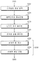
- FIG. 1 is a flowchart illustrating a panorama image providing method according to an embodiment of the present invention.
- FIG. 2 is a diagram illustrating a difference in scan plane length according to a depth of an image layer.
- FIG. 3 is an exemplary diagram illustrating an example of converting a scan surface length of an image shown in FIG. 2 to the same size according to an embodiment of the present invention.
- FIG. 4 is a flowchart illustrating in detail an optimal image selection step of the panorama image providing method according to FIG. 1.
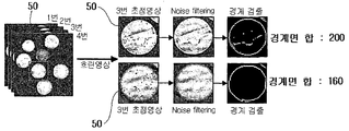
- FIG. 5 is an exemplary diagram illustrating selecting an optimal image using a sum of boundary information according to an embodiment of the present invention.
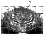
- FIG. 6 is an exemplary diagram illustrating an image divided into blocks for optimal image selection according to an embodiment of the present invention.
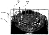
- FIG. 7 is an exemplary diagram illustrating an image divided into overlapping blocks for optimal image selection according to an embodiment of the present invention.
- FIG. 8 is an exemplary diagram illustrating a block phenomenon generated due to a difference in image layers when combining selected images according to an embodiment of the present invention.
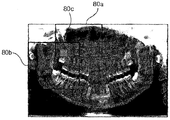
- FIG. 9 is an exemplary diagram illustrating an interpolation method according to an embodiment of the present invention for removing the block phenomenon shown in FIG. 8.
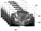
- FIG. 10 is an exemplary diagram illustrating limiting a selection range of an optimal image by setting one optimal image selected as an initial value according to an embodiment of the present invention.
- FIG. 11 is a block diagram of an image providing apparatus according to an embodiment of the present invention.
- FIG. 1 is a flowchart illustrating a panorama image providing method according to an embodiment of the present invention.
- the method comprises: scaling an image so that reconstructed images have the same size (S100), selecting a clear image (S200), and providing a panoramic image. It includes a step (S300).
- the scaling of the image (S100) is a step of reconstructing the image photographed by the imager according to one or more preset image layers.
- the image layer refers to a plane formed by three-dimensional virtual segments or segments formed by focal points for defining or specifying a position of an object to be photographed (the arch surface including a tooth in the case of a dental image). If the tooth to be photographed on the dental panoramic image and the focal plane coincide with each other, the resulting panoramic image can be obtained clearly.
- various image layers are predefined and used in consideration of various spatial distributions of objects.
- the image according to an embodiment of the present invention may be a frame image of a frame unit acquired by the panorama image acquisition device, or may be a panorama image which is a final result, for example, as an image generated by reconstruction.
- the panoramic image capturing apparatus includes an X-ray light source, an image sensor, and an image processing apparatus.
- X-ray light sources rotate X-rays around a subject along certain trajectories.
- the X-ray light source irradiates X-rays to a plurality of image layer trajectories in which a region of interest of a subject is located.
- the image sensor has a constant area and moves in association with the X-ray light source with the cross body interposed therebetween, and receives the X-rays to acquire images of a plurality of image layer trajectories.
- the image processing apparatus receives the images acquired from the image sensor, reconstructs the image of the image layer trajectory, and reconstructs the panorama image of the final trajectory.
- the image layer trajectory in this embodiment includes the arch surface by the imager.
- the reconstructed image of the frame image photographed by the panoramic image capturing apparatus or the size of frame images used for reconstruction is changed.
- the reconstructed image may be changed in consideration of the size of a predetermined reference image.
- the predetermined reference image is preferably an image reconstructed according to an image layer corresponding to a general arch surface in consideration of the patient's body information. Physical information is preferably information including the age, sex, height, weight of the patient.
- the scaling of the image (S100) may include changing the size of the image (S110) and overlapping the changed image (S120).
- the size of the image receives a frame image captured by the panoramic image capturing apparatus (S112), and receives a scan length according to the depth of focus of the image layer for the frame image.
- the size of the overlapping images is equally changed using the scan length.
- the depth means the distance between the panoramic imager and the image layer, and preferably, the depth of the image layer relative to the arch surface photographed by the dental panoramic imager.
- the scan length refers to a relative length of the ROI that is transmitted when X-rays radiated from the panoramic photographing apparatus pass through the ROI that is to be irradiated. The deeper the depth of the image layer, the greater the scan length of the X-ray.
- the scan length of the first scan surface 15 along the first image layer 10 is relatively shorter than the scan length of the second scan surface 25 along the second image layer 20. Therefore, even when the X-ray 5 irradiated from the panoramic photographing device passes through the same portion of the ROI to be irradiated, the relative size of the ROI in the image received from the image sensor 30 varies depending on the image layer. It is preferable to change the size of the images to the same size by using the length of the scan surface according to the depth of the layer.
- the scan length of the image layer is calculated based on the width of the X-ray radiated by the panoramic image capturing apparatus, and the scan length of the frame image of the region of interest to be scanned corresponds to a predetermined reference pixel value. It is desirable to change the size of.
- the predetermined reference pixel value is preferably a pixel value such that the scan length of the ROI constitutes one pixel in each frame image.
- the frame images to be superimposed are selected from the changed images in step S110, and the selected frame images are overlapped at a predetermined interval (S122).
- An overlapping scaling image is generated (S124).
- the predetermined interval refers to the degree of overlap of the frame images according to the depth of the image layer when the frame images are superimposed according to a graphic unit including pixels to generate a panorama image.
- the overlapping degree is preferably reduced.
- the overlapping degree may be changed according to the original scan length of the frame image. have.
- step S200 of selecting the optimal images having the optimal sharpness the image having the optimal sharpness is selected by analyzing the sharpness of the reconstructed images having the same size in the step S100 of scaling the image. Selecting images (S200) will be described in more detail with reference to FIG. 4. 4 is a flowchart illustrating in detail an optimal image selection step of the panorama image providing method according to FIG. 1.
- Selecting images includes removing noise existing in the image (S210), detecting an interface from the image from which the noise has been removed (S220), and selecting an optimal image using the detected boundary information. Selecting step (S230).
- the scaled image Prior to the step of removing noise (S210), the scaled image is received in step S100, and the scaled image is input (S202), and the received image is divided into block units (S204) to remove the noise (S210) and boundary detection ( It is preferable to perform S220).
- the step S210 of removing noise present in the image removes all components other than a signal included in the image information.
- Noise is a component other than a signal included in an original image, and may be generated by external light or reflection, and includes a level of meaningless signal existing in nature.
- the system noise of the equipment and the noise component due to the X-ray distribution are always present in all the images, and when the noise component is stronger than the signal size of the image, the noise-amplified image may be selected.
- a predetermined algorithm is applied to each partial image.
- the predetermined algorithm is preferably a noise removal filter including a plurality of filters such as a Poisson distribution conversion filter in consideration of the X-ray distribution, including a general Gaussian type filter and a mean filter.
- the boundary surface is a plane that separates the ROI (the arch surface) and the background region other than the ROI to be photographed by the panoramic image photographing apparatus.
- the detection of the interface is preferably performed using a Sobel Mask. The interface exists at the point where the brightness of the image changes from low to high, or vice versa, thereby representing the shape, size and texture of the object. It is preferable to find the pixel corresponding to the boundary surface in detail by obtaining boundary information of the image using the detection of the boundary surface.
- the mask for detecting the rate of change is preferably a Sobel Mask.
- the Sobel mask detects edges in all directions, resists noise, and is more sensitive to diagonal lines than vertical and horizontal boundaries.
- the size of the mask is preferably any one of 3x3, 5x5, and 7x7, and as the size of the mask increases, the thickness of the interface becomes thicker and clearer.
- the mask may include a Laplacian mask according to a vertical, horizontal mask, or second derivative.
- step S230 the optimal image is selected using the detected boundary surface information, and the sharpness of the images is analyzed using the boundary surface information, and the image having the optimal sharpness is selected.
- the step of selecting an optimal image calculates the sum of the boundary surfaces detected in the detection of the boundary surface (S220) (S232), and selects a clear image using the boundary surface sum (S234). It is preferable to select an image having the largest number of boundary pixels as an optimal image by comparing the sum of the boundary surfaces.
- the sum of the boundary planes means the relative number of pixels detected as the boundary planes in the image. Selecting an optimal image using the detected boundary surface information (S230) will be described in detail with reference to FIG. 5.
- Images 1 to 4 may be images including the ROI 50.
- the sum of the boundary surfaces detected in the fourth image is 160 or the sum of the boundary surfaces detected in the third image is 200. Therefore, if the sum of the boundary surfaces of the first and second images does not exceed 200, the third image is selected. It is preferable.
- the sharpness is preferably the degree of matching between the image layer and the shape of the subject when the image is most clearly expressed when the image layer of the image matches the geometry of the subject. According to this embodiment, it is preferable that the sharpness is maximum when the sum of the boundary surfaces is maximum.
- step of selecting images according to the present embodiment in analyzing the sharpness, it is preferable to divide the images into a plurality of blocks and to analyze the sharpness of the divided images. Dividing the image into blocks will be described with reference to FIG. 6. 6 is an exemplary diagram illustrating an image divided into blocks 60 for optimal image selection according to an embodiment of the present invention. According to the present exemplary embodiment, it is preferable to divide an image of the arch surface into blocks 60 and to select an image having an optimal sharpness for each of the divided images.
- the step S200 of selecting images may be divided into overlapping blocks 60a, 60b, and 60c that share some of the images, as shown in FIG. 7, and the sharpness of the divided images may be analyzed.
- Do. 7 is an exemplary diagram illustrating an image divided into overlapping blocks for optimal image selection according to an embodiment of the present invention. Each of the three blocks 60a, 60b, and 60c divided by a dotted line shares a certain portion, and analyzes sharpness of overlapping blocks.
- one combined image is generated by combining the optimal images selected in the selecting of the images (S200).
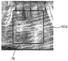
- dividing an image when the image is divided into blocks 60a without overlapping as shown in FIG. 6, a block phenomenon may occur in the combined image because the image layers of the images corresponding to each block are different.
- a boundary surface that does not exist in a real object occurs at a portion of an image, which will be described in detail with reference to FIG. 8.
- FIG. 8 is an exemplary diagram illustrating a block phenomenon generated due to a difference in image layers when combining selected images according to an embodiment of the present invention.
- a block phenomenon occurs in the image 70 of the root portion of the block 60 indicated by a solid line.
- the optimal images selected in the selecting of the images (S200) may be interpolated and combined. Images that are interpolated and combined are preferably divided into overlapping blocks that share some of the images in step S200, and are screened by analyzing the sharpness of the divided images. In interpolation, it is preferable to estimate an image layer of a specific region using image layers of one or more images sharing a specific region with respect to a specific region shared by the selected images.
- FIG. 9 is an exemplary diagram illustrating an interpolation method according to an embodiment of the present invention for removing the block phenomenon shown in FIG. 8. According to the present exemplary embodiment, it is preferable to estimate the image layer of the specific region 80c shared by the two blocks 80a and 80b shown in FIG. 9 using interpolation.
- the combined image in step S300 may include an area where the connection region is not continuous.
- the generating of the combined image (S300) may be performed by selecting one of the images selected in the selecting of the images (S200) as an initial value, and selecting the images (S200). It is desirable to limit the range of images.
- the image set as an initial value in the present embodiment is preferably an image selected as an optimal image with respect to the block having the smallest noise, and the image captured by the dental panoramic image capturing apparatus includes a posterior portion.
- the limited images are preferably images of a block 98 neighboring a block of an image set as an initial value. In the step S200 of selecting images according to the present exemplary embodiment, it is preferable to analyze sharpness while repeatedly extending the neighboring blocks based on the blocks of the image set as initial values.
- the image generated by combining the optimal images selected in the selecting of the images (S200) is provided to the user through the display unit 400.
- the panoramic image photographing apparatus rotates around a subject along a predetermined trajectory and irradiates X-rays, and the irradiated X-ray passes through the subject and is received by an image sensor moving in association with the X-ray light source. It is preferable that this is an image to form.
- FIG. 11 is a block diagram of an image providing apparatus 1 according to an embodiment of the present invention.
- the image providing apparatus 1 includes an image scaling unit 100 for scaling an image so that reconstructed images have the same size, an image selecting unit 200 for selecting a clear image, and a panorama using the selected images.
- the image scaling unit 100 scales an image of a frame image photographed by the panoramic image capturing apparatus or a frame image used for reconstruction as described above (S100). As described above, when the scaled image is a reconstructed image, the reconstructed image may be changed in size in consideration of the size of a predetermined reference image. When the scaled image is a frame image, according to the present exemplary embodiment, frame images photographed by the panoramic image capturing apparatus are received and reconstructed according to one or more preset image layers.
- the image scaling unit 100 includes a size changing unit 110 for changing the size of the overlapping image, and an overlapping unit 120 for overlapping the changed image.
- the image size changing unit 110 receives a frame image photographed by the panoramic image capturing apparatus (S112), and receives a scan length according to the depth of focus of the image layer with respect to the frame image (S1114). Using the scan length, the size of overlapping images is changed to be the same (S116). As described above, the size of the overlapping images is equally changed by using the scan length according to the depth of focus of the image layer of the image.
- the image superimposing unit 120 selects frame images to be superimposed among the changed images in the step S110 of changing an image size as described above, superimposes the selected frame images at a predetermined interval (S122). The superimposed scaling image is generated (S124).
- the image selector 200 may include a noise remover 210 to remove noise of an image, an edge detector 220 to detect an interface of an image from which the noise is removed, and an image selector to select an optimal image using boundary information. 230). As described above, the image selector 200 analyzes the sharpness of the images scaled by the image scaler 100 and selects an image having an optimal sharpness (S200).
- the noise removing unit 210 receives the scaled image from the image scaling unit 100 before removing the noise (S210), and divides the received image into block units (S204) to remove the noise. It is preferable to perform (S210) and boundary detection (S220).
- the noise removing unit 210 removes all components other than the signal included in the image information (S210).
- the boundary detector 220 detects an interface with respect to the images from which the noise is removed by the noise remover 210 (S220).
- the selector 230 analyzes the sharpness of the images by using the boundary information detected by the boundary detector 220 and selects an image having an optimal sharpness (S230).
- the panoramic image generating unit 300 generates a single combined image by combining the clear images selected by the image selecting unit 200 as described above (S300).
- the display unit 400 receives the image generated by the combined image generator 300 and displays the combined image to the user.
- the panorama image providing method of the present invention can be implemented in a computer-readable code on a computer-readable recording medium.
- the computer-readable recording medium includes all kinds of recording devices in which data that can be read by a computer system is stored.
- Examples of computer-readable recording media include ROM, RAM, CD-ROM, magnetic tape, floppy disks, optical data storage devices, and the like, and computer-readable recording media are distributed in networked computer systems.
- Computer-readable code can be stored and executed in a distributed fashion. And functional programs, codes and code segments for implementing the present invention can be easily inferred by programmers in the art to which the present invention belongs.
Landscapes
- Engineering & Computer Science (AREA)
- Physics & Mathematics (AREA)
- General Physics & Mathematics (AREA)
- Theoretical Computer Science (AREA)
- Computer Vision & Pattern Recognition (AREA)
- Signal Processing (AREA)
- Multimedia (AREA)
- Health & Medical Sciences (AREA)
- General Health & Medical Sciences (AREA)
- Medical Informatics (AREA)
- Nuclear Medicine, Radiotherapy & Molecular Imaging (AREA)
- Radiology & Medical Imaging (AREA)
- Quality & Reliability (AREA)
- Image Processing (AREA)
- Apparatus For Radiation Diagnosis (AREA)
Priority Applications (4)
| Application Number | Priority Date | Filing Date | Title |
|---|---|---|---|
| US14/401,726 US9514516B2 (en) | 2012-05-16 | 2013-05-16 | Method and apparatus for providing panorama image data |
| EP13790689.7A EP2852153B1 (de) | 2012-05-16 | 2013-05-16 | Verfahren und vorrichtung zur bereitstellung von panoramabilddaten |
| US15/352,627 US9852525B2 (en) | 2012-05-16 | 2016-11-16 | Method and apparatus for providing panorama image data |
| US15/852,360 US10181206B2 (en) | 2012-05-16 | 2017-12-22 | Method and apparatus for providing panorama image data |
Applications Claiming Priority (2)
| Application Number | Priority Date | Filing Date | Title |
|---|---|---|---|
| KR10-2012-0051936 | 2012-05-16 | ||
| KR1020120051936A KR101389841B1 (ko) | 2012-05-16 | 2012-05-16 | 파노라마 영상 데이터 제공 방법 및 장치 |
Related Child Applications (2)
| Application Number | Title | Priority Date | Filing Date |
|---|---|---|---|
| US14/401,726 A-371-Of-International US9514516B2 (en) | 2012-05-16 | 2013-05-16 | Method and apparatus for providing panorama image data |
| US15/352,627 Continuation US9852525B2 (en) | 2012-05-16 | 2016-11-16 | Method and apparatus for providing panorama image data |
Publications (1)
| Publication Number | Publication Date |
|---|---|
| WO2013172676A1 true WO2013172676A1 (ko) | 2013-11-21 |
Family
ID=49584014
Family Applications (1)
| Application Number | Title | Priority Date | Filing Date |
|---|---|---|---|
| PCT/KR2013/004367 Ceased WO2013172676A1 (ko) | 2012-05-16 | 2013-05-16 | 파노라마 영상 데이터 제공 방법 및 장치 |
Country Status (4)
| Country | Link |
|---|---|
| US (3) | US9514516B2 (de) |
| EP (1) | EP2852153B1 (de) |
| KR (1) | KR101389841B1 (de) |
| WO (1) | WO2013172676A1 (de) |
Cited By (3)
| Publication number | Priority date | Publication date | Assignee | Title |
|---|---|---|---|---|
| EP3209212A4 (de) * | 2014-09-16 | 2019-01-09 | Sirona Dental, Inc. | Verfahren, systeme, vorrichtungen und computerprogramme zur verarbeitung von tomografischen bildern |
| CN109636874A (zh) * | 2018-12-17 | 2019-04-16 | 浙江科澜信息技术有限公司 | 一种三维模型透视投影方法、系统及相关装置 |
| CN110033413A (zh) * | 2018-12-29 | 2019-07-19 | 阿里巴巴集团控股有限公司 | 客户端的图像处理方法、装置、电子设备、计算机可读介质 |
Families Citing this family (25)
| Publication number | Priority date | Publication date | Assignee | Title |
|---|---|---|---|---|
| KR101826704B1 (ko) | 2013-09-13 | 2018-02-08 | 인텔 코포레이션 | 비디오 프로덕션 공유 장치 및 방법 |
| WO2016015623A1 (en) * | 2014-07-28 | 2016-02-04 | Mediatek Inc. | Portable device with adaptive panoramic image processor |
| KR101669178B1 (ko) * | 2014-12-31 | 2016-10-27 | 오스템임플란트 주식회사 | 치아 파노라마 영상 생성방법, 이를 위한 장치 및 이를 기록한 기록매체 |
| US20160295108A1 (en) * | 2015-04-01 | 2016-10-06 | Cheng Cao | System and method for panoramic imaging |
| EP3465609A1 (de) * | 2016-05-27 | 2019-04-10 | Trophy | Verfahren zur erstellung eines zusammengesetzten zephalometrischen bildes |
| CN108491707B (zh) * | 2016-05-30 | 2020-01-14 | Oppo广东移动通信有限公司 | 一种解锁控制方法及终端设备和介质产品 |
| US10674971B2 (en) | 2016-10-18 | 2020-06-09 | Vatech Co., Ltd. | X-ray image display apparatus and method for X-ray image display |
| EP3311750A1 (de) | 2016-10-18 | 2018-04-25 | Vatech Co. Ltd. | Herstellung einer panoramischen radiografie |
| KR102079576B1 (ko) | 2016-10-18 | 2020-02-20 | 주식회사 바텍 | 엑스선 파노라마 영상 표시 장치 및 방법 |
| CN107027071B (zh) * | 2017-03-14 | 2019-12-13 | 深圳市创达天盛智能科技有限公司 | 一种视频播放的方法和装置 |
| US10417276B2 (en) * | 2017-05-15 | 2019-09-17 | Adobe, Inc. | Thumbnail generation from panoramic images |
| CN107346546B (zh) * | 2017-07-17 | 2021-05-04 | 京东方科技集团股份有限公司 | 一种图像处理方法及装置 |
| KR101954845B1 (ko) * | 2017-10-30 | 2019-03-06 | 오스템임플란트 주식회사 | 치아의 악궁 라인 추출 장치 및 그 방법 |
| CN108682008B (zh) * | 2018-05-07 | 2019-04-16 | 江苏康尚生物医疗科技有限公司 | 一种白细胞图像清晰度评价方法及装置 |
| KR102155745B1 (ko) * | 2019-01-16 | 2020-09-14 | 오스템임플란트 주식회사 | Fmx 자동 생성 방법 및 그 장치 |
| CN109934876B (zh) * | 2019-01-25 | 2023-11-24 | 淮阴师范学院 | 一种基于二阶矩函数的图像聚焦测度实现方法 |
| KR102200060B1 (ko) | 2019-02-20 | 2021-01-08 | 오스템임플란트 주식회사 | 치아의 정밀 진단 모듈로의 간편한 이동 방법 및 그 장치 |
| EP3730057B1 (de) * | 2019-04-26 | 2022-12-28 | Sirona Dental Systems GmbH | Verfahren und vorrichtung zur erzeugung eines panoramaschichtbildes |
| EP4116925B1 (de) * | 2021-07-09 | 2025-02-26 | See Through S.r.l. | Bildverarbeitungsverfahren zur erzeugung eines panoramabildes |
| US12306007B2 (en) * | 2021-11-12 | 2025-05-20 | Rockwell Collins, Inc. | System and method for chart thumbnail image generation |
| US12254282B2 (en) | 2021-11-12 | 2025-03-18 | Rockwell Collins, Inc. | Method for automatically matching chart names |
| US12304648B2 (en) | 2021-11-12 | 2025-05-20 | Rockwell Collins, Inc. | System and method for separating avionics charts into a plurality of display panels |
| KR102765879B1 (ko) | 2022-05-02 | 2025-02-11 | 주식회사바텍 | 엑스선 파노라마 영상 표시 장치 |
| KR102672173B1 (ko) * | 2023-04-14 | 2024-06-07 | 주식회사 오비젠 | 인공지능 기반의 치아 간 인접면 충치 감별 시스템 및 방법 |
| KR102927072B1 (ko) * | 2023-12-01 | 2026-02-12 | 김연우 | 대형 led 스크린 제어방법 |
Citations (4)
| Publication number | Priority date | Publication date | Assignee | Title |
|---|---|---|---|---|
| JP2008086659A (ja) * | 2006-10-04 | 2008-04-17 | Axion Japan:Kk | 画像処理方法及びパノラマ画像撮影装置 |
| JP2010011910A (ja) * | 2008-07-01 | 2010-01-21 | Yoshida Dental Mfg Co Ltd | デジタルパノラマ撮影装置およびパノラマ用画像処理プログラム |
| JP2010148676A (ja) * | 2008-12-25 | 2010-07-08 | Yoshida Dental Mfg Co Ltd | X線撮影装置およびパノラマ用画像処理プログラム |
| JP2012061016A (ja) * | 2010-09-14 | 2012-03-29 | Asahi Roentgen Kogyo Kk | X線ct撮影装置及びx線ct画像の表示方法 |
Family Cites Families (15)
| Publication number | Priority date | Publication date | Assignee | Title |
|---|---|---|---|---|
| US4176278A (en) | 1978-10-30 | 1979-11-27 | Pennwalt Corporation | Panoramic dental radiography employing intraoral radiation source and image intensifying means |
| JP3441578B2 (ja) | 1995-11-22 | 2003-09-02 | 株式会社モリタ製作所 | 歯科用パノラマx線撮影装置 |
| US7397890B2 (en) | 2005-04-25 | 2008-07-08 | Xoran Technologies, Inc. | CT system with synthetic view generation |
| US8295432B2 (en) | 2005-05-02 | 2012-10-23 | Oy Ajat Ltd | Radiation imaging device with irregular rectangular shape and extraoral dental imaging system therefrom |
| US7742560B2 (en) | 2005-05-02 | 2010-06-22 | Oy Ajat Ltd. | Radiation imaging device with irregular rectangular shape and extraoral dental imaging system therefrom |
| US7336763B2 (en) | 2005-05-02 | 2008-02-26 | Oy Ajat Ltd | Dental extra-oral x-ray imaging system and method |
| US9332950B2 (en) | 2005-05-02 | 2016-05-10 | Oy Ajat Ltd. | Radiation imaging device with irregular rectangular shape and extraoral dental imaging system therefrom |
| US7676022B2 (en) | 2005-05-02 | 2010-03-09 | Oy Ajat Ltd. | Extra-oral digital panoramic dental x-ray imaging system |
| US8401267B2 (en) * | 2008-04-30 | 2013-03-19 | J. Morita Manufacturing Corporation | Medical X-ray CT imaging apparatus |
| KR101043331B1 (ko) * | 2009-04-30 | 2011-06-23 | 알피니언메디칼시스템 주식회사 | 초음파진단시스템의 실시간 다시점 3차원 초음파 영상 사용자 인터페이스 장치 및 방법 |
| KR101196208B1 (ko) * | 2009-11-02 | 2012-11-05 | 삼성메디슨 주식회사 | 의료 진단 장비 및 데이터 전송방법 |
| KR101094180B1 (ko) * | 2009-11-10 | 2011-12-14 | 주식회사바텍 | 파노라마 영상 획득 방법 및 장치 |
| JP5757660B2 (ja) * | 2010-08-11 | 2015-07-29 | 学校法人日本大学 | X線撮影装置 |
| WO2012139031A1 (en) | 2011-04-06 | 2012-10-11 | The Trustees Of Columbia University In The City Of New York | System, method and computer-accessible medium for providing a panoramic cone beam computed tomography (cbct) |
| US9269168B2 (en) | 2013-03-15 | 2016-02-23 | Carestream Health, Inc. | Volume image reconstruction using data from multiple energy spectra |
-
2012
- 2012-05-16 KR KR1020120051936A patent/KR101389841B1/ko active Active
-
2013
- 2013-05-16 US US14/401,726 patent/US9514516B2/en active Active
- 2013-05-16 WO PCT/KR2013/004367 patent/WO2013172676A1/ko not_active Ceased
- 2013-05-16 EP EP13790689.7A patent/EP2852153B1/de active Active
-
2016
- 2016-11-16 US US15/352,627 patent/US9852525B2/en active Active
-
2017
- 2017-12-22 US US15/852,360 patent/US10181206B2/en active Active
Patent Citations (4)
| Publication number | Priority date | Publication date | Assignee | Title |
|---|---|---|---|---|
| JP2008086659A (ja) * | 2006-10-04 | 2008-04-17 | Axion Japan:Kk | 画像処理方法及びパノラマ画像撮影装置 |
| JP2010011910A (ja) * | 2008-07-01 | 2010-01-21 | Yoshida Dental Mfg Co Ltd | デジタルパノラマ撮影装置およびパノラマ用画像処理プログラム |
| JP2010148676A (ja) * | 2008-12-25 | 2010-07-08 | Yoshida Dental Mfg Co Ltd | X線撮影装置およびパノラマ用画像処理プログラム |
| JP2012061016A (ja) * | 2010-09-14 | 2012-03-29 | Asahi Roentgen Kogyo Kk | X線ct撮影装置及びx線ct画像の表示方法 |
Non-Patent Citations (1)
| Title |
|---|
| See also references of EP2852153A4 * |
Cited By (5)
| Publication number | Priority date | Publication date | Assignee | Title |
|---|---|---|---|---|
| EP3209212A4 (de) * | 2014-09-16 | 2019-01-09 | Sirona Dental, Inc. | Verfahren, systeme, vorrichtungen und computerprogramme zur verarbeitung von tomografischen bildern |
| US10912530B2 (en) | 2014-09-16 | 2021-02-09 | DENTSPLY SIRONA, Inc. | Methods, systems, apparatuses, and computer programs for processing tomographic images |
| CN109636874A (zh) * | 2018-12-17 | 2019-04-16 | 浙江科澜信息技术有限公司 | 一种三维模型透视投影方法、系统及相关装置 |
| CN110033413A (zh) * | 2018-12-29 | 2019-07-19 | 阿里巴巴集团控股有限公司 | 客户端的图像处理方法、装置、电子设备、计算机可读介质 |
| CN110033413B (zh) * | 2018-12-29 | 2023-08-18 | 阿里巴巴集团控股有限公司 | 客户端的图像处理方法、装置、设备、计算机可读介质 |
Also Published As
| Publication number | Publication date |
|---|---|
| EP2852153A4 (de) | 2016-01-13 |
| US20150139524A1 (en) | 2015-05-21 |
| US9852525B2 (en) | 2017-12-26 |
| US20170061651A1 (en) | 2017-03-02 |
| EP2852153B1 (de) | 2018-06-27 |
| US10181206B2 (en) | 2019-01-15 |
| US9514516B2 (en) | 2016-12-06 |
| US20180122106A1 (en) | 2018-05-03 |
| KR20130128124A (ko) | 2013-11-26 |
| KR101389841B1 (ko) | 2014-04-29 |
| EP2852153A1 (de) | 2015-03-25 |
Similar Documents
| Publication | Publication Date | Title |
|---|---|---|
| WO2013172676A1 (ko) | 파노라마 영상 데이터 제공 방법 및 장치 | |
| KR101167567B1 (ko) | 어류 모니터링을 위한 영상감시장치 및 방법 | |
| JP2001250119A (ja) | 信号処理装置および方法、並びに記録媒体 | |
| JP2013500536A5 (de) | ||
| JP6418922B2 (ja) | 画像処理装置および画像処理方法 | |
| US9183625B2 (en) | Method of processing radiograph and apparatus for processing radiograph using the method in which hough transform and radon transform performed on image | |
| WO2023229118A1 (ko) | 방사선 촬영에 의해 획득된 영상에 포함된 노이즈를 저감하기 위한 영상 처리 방법 및 장치 | |
| WO2015069063A1 (en) | Method and system for creating a camera refocus effect | |
| WO2013172685A1 (ko) | X선 파노라마 영상 재구성 장치 및 방법 | |
| CN107203983B (zh) | 用于减少x射线图像中的栅线伪影的方法及系统 | |
| US9867586B2 (en) | Stereo X-ray tube based suppression of outside body high contrast objects | |
| JP2002507134A (ja) | X線画像処理 | |
| WO2015026164A1 (ko) | 스캔 영상의 복원 방법, 장치 및 이를 저장하는 기록매체 | |
| US20130308841A1 (en) | Method and apparatus for image processing | |
| JP2007272532A (ja) | 火災検出装置 | |
| JP2014176565A (ja) | 画像処理装置、放射線撮影装置、画像処理方法、コンピュータプログラム及び記憶媒体 | |
| WO2011001328A1 (en) | Digital image subtraction | |
| JP4746761B2 (ja) | 放射線画像処理装置、放射線画像処理方法、記憶媒体、及びプログラム | |
| US8867699B2 (en) | Radiographic device | |
| JP2017217170A (ja) | 画像表示装置 | |
| JP2004351056A (ja) | 医用画像処理装置 | |
| JP7033931B2 (ja) | 画像処理装置、画像処理方法、及び画像処理プログラム | |
| WO2019022307A1 (ko) | 환자의 3차원 골격 모델을 생성하는 방법 | |
| JP2017017551A (ja) | 画像処理装置及び画像処理方法 | |
| JPH09229648A (ja) | 画像情報入出力装置及び画像情報入出力方法 |
Legal Events
| Date | Code | Title | Description |
|---|---|---|---|
| 121 | Ep: the epo has been informed by wipo that ep was designated in this application |
Ref document number: 13790689 Country of ref document: EP Kind code of ref document: A1 |
|
| NENP | Non-entry into the national phase |
Ref country code: DE |
|
| WWE | Wipo information: entry into national phase |
Ref document number: 14401726 Country of ref document: US |
|
| WWE | Wipo information: entry into national phase |
Ref document number: 2013790689 Country of ref document: EP |