WO2013175708A1 - Structure de protection contre le reflux pour compresseur - Google Patents
Structure de protection contre le reflux pour compresseur Download PDFInfo
- Publication number
- WO2013175708A1 WO2013175708A1 PCT/JP2013/002692 JP2013002692W WO2013175708A1 WO 2013175708 A1 WO2013175708 A1 WO 2013175708A1 JP 2013002692 W JP2013002692 W JP 2013002692W WO 2013175708 A1 WO2013175708 A1 WO 2013175708A1
- Authority
- WO
- WIPO (PCT)
- Prior art keywords
- passage
- compression chamber
- valve
- chamber
- inflow port
- Prior art date
- Legal status (The legal status is an assumption and is not a legal conclusion. Google has not performed a legal analysis and makes no representation as to the accuracy of the status listed.)
- Ceased
Links
Images



Classifications
-
- F—MECHANICAL ENGINEERING; LIGHTING; HEATING; WEAPONS; BLASTING
- F04—POSITIVE - DISPLACEMENT MACHINES FOR LIQUIDS; PUMPS FOR LIQUIDS OR ELASTIC FLUIDS
- F04B—POSITIVE-DISPLACEMENT MACHINES FOR LIQUIDS; PUMPS
- F04B39/00—Component parts, details, or accessories, of pumps or pumping systems specially adapted for elastic fluids, not otherwise provided for in, or of interest apart from, groups F04B25/00 - F04B37/00
- F04B39/04—Measures to avoid lubricant contaminating the pumped fluid
-
- F—MECHANICAL ENGINEERING; LIGHTING; HEATING; WEAPONS; BLASTING
- F04—POSITIVE - DISPLACEMENT MACHINES FOR LIQUIDS; PUMPS FOR LIQUIDS OR ELASTIC FLUIDS
- F04B—POSITIVE-DISPLACEMENT MACHINES FOR LIQUIDS; PUMPS
- F04B39/00—Component parts, details, or accessories, of pumps or pumping systems specially adapted for elastic fluids, not otherwise provided for in, or of interest apart from, groups F04B25/00 - F04B37/00
- F04B39/06—Cooling; Heating; Prevention of freezing
-
- F—MECHANICAL ENGINEERING; LIGHTING; HEATING; WEAPONS; BLASTING
- F04—POSITIVE - DISPLACEMENT MACHINES FOR LIQUIDS; PUMPS FOR LIQUIDS OR ELASTIC FLUIDS
- F04B—POSITIVE-DISPLACEMENT MACHINES FOR LIQUIDS; PUMPS
- F04B39/00—Component parts, details, or accessories, of pumps or pumping systems specially adapted for elastic fluids, not otherwise provided for in, or of interest apart from, groups F04B25/00 - F04B37/00
- F04B39/10—Adaptations or arrangements of distribution members
-
- F—MECHANICAL ENGINEERING; LIGHTING; HEATING; WEAPONS; BLASTING
- F04—POSITIVE - DISPLACEMENT MACHINES FOR LIQUIDS; PUMPS FOR LIQUIDS OR ELASTIC FLUIDS
- F04C—ROTARY-PISTON, OR OSCILLATING-PISTON, POSITIVE-DISPLACEMENT MACHINES FOR LIQUIDS; ROTARY-PISTON, OR OSCILLATING-PISTON, POSITIVE-DISPLACEMENT PUMPS
- F04C29/00—Component parts, details or accessories of pumps or pumping installations, not provided for in groups F04C18/00 - F04C28/00
- F04C29/12—Arrangements for admission or discharge of the working fluid, e.g. constructional features of the inlet or outlet
- F04C29/124—Arrangements for admission or discharge of the working fluid, e.g. constructional features of the inlet or outlet with inlet and outlet valves specially adapted for rotary or oscillating piston pumps
- F04C29/126—Arrangements for admission or discharge of the working fluid, e.g. constructional features of the inlet or outlet with inlet and outlet valves specially adapted for rotary or oscillating piston pumps of the non-return type
-
- F—MECHANICAL ENGINEERING; LIGHTING; HEATING; WEAPONS; BLASTING
- F16—ENGINEERING ELEMENTS AND UNITS; GENERAL MEASURES FOR PRODUCING AND MAINTAINING EFFECTIVE FUNCTIONING OF MACHINES OR INSTALLATIONS; THERMAL INSULATION IN GENERAL
- F16K—VALVES; TAPS; COCKS; ACTUATING-FLOATS; DEVICES FOR VENTING OR AERATING
- F16K15/00—Check valves
- F16K15/02—Check valves with guided rigid valve members
-
- F—MECHANICAL ENGINEERING; LIGHTING; HEATING; WEAPONS; BLASTING
- F25—REFRIGERATION OR COOLING; COMBINED HEATING AND REFRIGERATION SYSTEMS; HEAT PUMP SYSTEMS; MANUFACTURE OR STORAGE OF ICE; LIQUEFACTION SOLIDIFICATION OF GASES
- F25B—REFRIGERATION MACHINES, PLANTS OR SYSTEMS; COMBINED HEATING AND REFRIGERATION SYSTEMS; HEAT PUMP SYSTEMS
- F25B31/00—Compressor arrangements
- F25B31/02—Compressor arrangements of motor-compressor units
- F25B31/026—Compressor arrangements of motor-compressor units with compressor of rotary type
-
- F—MECHANICAL ENGINEERING; LIGHTING; HEATING; WEAPONS; BLASTING
- F25—REFRIGERATION OR COOLING; COMBINED HEATING AND REFRIGERATION SYSTEMS; HEAT PUMP SYSTEMS; MANUFACTURE OR STORAGE OF ICE; LIQUEFACTION SOLIDIFICATION OF GASES
- F25B—REFRIGERATION MACHINES, PLANTS OR SYSTEMS; COMBINED HEATING AND REFRIGERATION SYSTEMS; HEAT PUMP SYSTEMS
- F25B41/00—Fluid-circulation arrangements
- F25B41/30—Expansion means; Dispositions thereof
- F25B41/39—Dispositions with two or more expansion means arranged in series, i.e. multi-stage expansion, on a refrigerant line leading to the same evaporator
-
- F—MECHANICAL ENGINEERING; LIGHTING; HEATING; WEAPONS; BLASTING
- F04—POSITIVE - DISPLACEMENT MACHINES FOR LIQUIDS; PUMPS FOR LIQUIDS OR ELASTIC FLUIDS
- F04C—ROTARY-PISTON, OR OSCILLATING-PISTON, POSITIVE-DISPLACEMENT MACHINES FOR LIQUIDS; ROTARY-PISTON, OR OSCILLATING-PISTON, POSITIVE-DISPLACEMENT PUMPS
- F04C18/00—Rotary-piston pumps specially adapted for elastic fluids
- F04C18/02—Rotary-piston pumps specially adapted for elastic fluids of arcuate-engagement type, i.e. with circular translatory movement of co-operating members, each member having the same number of teeth or tooth-equivalents
- F04C18/0207—Rotary-piston pumps specially adapted for elastic fluids of arcuate-engagement type, i.e. with circular translatory movement of co-operating members, each member having the same number of teeth or tooth-equivalents both members having co-operating elements in spiral form
- F04C18/0215—Rotary-piston pumps specially adapted for elastic fluids of arcuate-engagement type, i.e. with circular translatory movement of co-operating members, each member having the same number of teeth or tooth-equivalents both members having co-operating elements in spiral form where only one member is moving
-
- F—MECHANICAL ENGINEERING; LIGHTING; HEATING; WEAPONS; BLASTING
- F04—POSITIVE - DISPLACEMENT MACHINES FOR LIQUIDS; PUMPS FOR LIQUIDS OR ELASTIC FLUIDS
- F04C—ROTARY-PISTON, OR OSCILLATING-PISTON, POSITIVE-DISPLACEMENT MACHINES FOR LIQUIDS; ROTARY-PISTON, OR OSCILLATING-PISTON, POSITIVE-DISPLACEMENT PUMPS
- F04C23/00—Combinations of two or more pumps, each being of rotary-piston or oscillating-piston type, specially adapted for elastic fluids; Pumping installations specially adapted for elastic fluids; Multi-stage pumps specially adapted for elastic fluids
- F04C23/008—Hermetic pumps
-
- F—MECHANICAL ENGINEERING; LIGHTING; HEATING; WEAPONS; BLASTING
- F25—REFRIGERATION OR COOLING; COMBINED HEATING AND REFRIGERATION SYSTEMS; HEAT PUMP SYSTEMS; MANUFACTURE OR STORAGE OF ICE; LIQUEFACTION SOLIDIFICATION OF GASES
- F25B—REFRIGERATION MACHINES, PLANTS OR SYSTEMS; COMBINED HEATING AND REFRIGERATION SYSTEMS; HEAT PUMP SYSTEMS
- F25B2309/00—Gas cycle refrigeration machines
- F25B2309/06—Compression machines, plants or systems characterised by the refrigerant being carbon dioxide
- F25B2309/061—Compression machines, plants or systems characterised by the refrigerant being carbon dioxide with cycle highest pressure above the supercritical pressure
-
- F—MECHANICAL ENGINEERING; LIGHTING; HEATING; WEAPONS; BLASTING
- F25—REFRIGERATION OR COOLING; COMBINED HEATING AND REFRIGERATION SYSTEMS; HEAT PUMP SYSTEMS; MANUFACTURE OR STORAGE OF ICE; LIQUEFACTION SOLIDIFICATION OF GASES
- F25B—REFRIGERATION MACHINES, PLANTS OR SYSTEMS; COMBINED HEATING AND REFRIGERATION SYSTEMS; HEAT PUMP SYSTEMS
- F25B2339/00—Details of evaporators; Details of condensers
- F25B2339/04—Details of condensers
- F25B2339/047—Water-cooled condensers
-
- F—MECHANICAL ENGINEERING; LIGHTING; HEATING; WEAPONS; BLASTING
- F25—REFRIGERATION OR COOLING; COMBINED HEATING AND REFRIGERATION SYSTEMS; HEAT PUMP SYSTEMS; MANUFACTURE OR STORAGE OF ICE; LIQUEFACTION SOLIDIFICATION OF GASES
- F25B—REFRIGERATION MACHINES, PLANTS OR SYSTEMS; COMBINED HEATING AND REFRIGERATION SYSTEMS; HEAT PUMP SYSTEMS
- F25B2400/00—Component parts or details not otherwise provided for in this subclass
- F25B2400/13—Economisers
-
- F—MECHANICAL ENGINEERING; LIGHTING; HEATING; WEAPONS; BLASTING
- F25—REFRIGERATION OR COOLING; COMBINED HEATING AND REFRIGERATION SYSTEMS; HEAT PUMP SYSTEMS; MANUFACTURE OR STORAGE OF ICE; LIQUEFACTION SOLIDIFICATION OF GASES
- F25B—REFRIGERATION MACHINES, PLANTS OR SYSTEMS; COMBINED HEATING AND REFRIGERATION SYSTEMS; HEAT PUMP SYSTEMS
- F25B2400/00—Component parts or details not otherwise provided for in this subclass
- F25B2400/23—Separators
-
- F—MECHANICAL ENGINEERING; LIGHTING; HEATING; WEAPONS; BLASTING
- F25—REFRIGERATION OR COOLING; COMBINED HEATING AND REFRIGERATION SYSTEMS; HEAT PUMP SYSTEMS; MANUFACTURE OR STORAGE OF ICE; LIQUEFACTION SOLIDIFICATION OF GASES
- F25B—REFRIGERATION MACHINES, PLANTS OR SYSTEMS; COMBINED HEATING AND REFRIGERATION SYSTEMS; HEAT PUMP SYSTEMS
- F25B30/00—Heat pumps
- F25B30/02—Heat pumps of the compression type
-
- F—MECHANICAL ENGINEERING; LIGHTING; HEATING; WEAPONS; BLASTING
- F25—REFRIGERATION OR COOLING; COMBINED HEATING AND REFRIGERATION SYSTEMS; HEAT PUMP SYSTEMS; MANUFACTURE OR STORAGE OF ICE; LIQUEFACTION SOLIDIFICATION OF GASES
- F25B—REFRIGERATION MACHINES, PLANTS OR SYSTEMS; COMBINED HEATING AND REFRIGERATION SYSTEMS; HEAT PUMP SYSTEMS
- F25B43/00—Arrangements for separating or purifying gases or liquids; Arrangements for vaporising the residuum of liquid refrigerant, e.g. by heat
- F25B43/02—Arrangements for separating or purifying gases or liquids; Arrangements for vaporising the residuum of liquid refrigerant, e.g. by heat for separating lubricants from the refrigerant
-
- F—MECHANICAL ENGINEERING; LIGHTING; HEATING; WEAPONS; BLASTING
- F25—REFRIGERATION OR COOLING; COMBINED HEATING AND REFRIGERATION SYSTEMS; HEAT PUMP SYSTEMS; MANUFACTURE OR STORAGE OF ICE; LIQUEFACTION SOLIDIFICATION OF GASES
- F25B—REFRIGERATION MACHINES, PLANTS OR SYSTEMS; COMBINED HEATING AND REFRIGERATION SYSTEMS; HEAT PUMP SYSTEMS
- F25B9/00—Compression machines, plants or systems, in which the refrigerant is air or other gas of low boiling point
- F25B9/002—Compression machines, plants or systems, in which the refrigerant is air or other gas of low boiling point characterised by the refrigerant
- F25B9/008—Compression machines, plants or systems, in which the refrigerant is air or other gas of low boiling point characterised by the refrigerant the refrigerant being carbon dioxide
Definitions
- the present disclosure relates to a structure for preventing a backflow of a compressor, and is effective when applied to a compressor of a refrigeration cycle that constitutes a gas injection cycle.
- a so-called gas injection cycle (economizer refrigeration cycle) is known as a cycle configuration for improving the coefficient of performance (COP) of a vapor compression refrigeration cycle.
- COP is improved by injecting and joining the intermediate-pressure gas-phase refrigerant of the cycle to the refrigerant in the pressurization process in the compression chamber of the compressor to improve the mechanical efficiency of the compressor.
- Patent Document 1 discloses a compressor including a backflow prevention structure configured using a free valve (spool valve).
- backflow prevention structure is constituted using a free valve for the purpose of realizing a backflow prevention structure of small size and simple composition.
- a backflow prevention structure if the free valve is not displaced quickly when the refrigerant pressure on the compression chamber side becomes higher than the refrigerant pressure on the intermediate pressure port side, the refrigerant is intermediate from the compression chamber. It will flow backward to the pressure port side and the COP improvement effect cannot be obtained sufficiently.
- the present disclosure aims to improve the responsiveness of a backflow prevention structure configured using a free valve.
- Another object of the present disclosure is to reduce the operating noise of the backflow prevention structure configured using a free valve.
- a compressor provided with an inflow port for allowing a fluid to be compressed to flow into the compression chamber.
- a check valve chamber formed in the fluid passage from the inflow port to the compression chamber, and a free valve that opens and closes the fluid passage from the inflow port to the compression chamber. The free valve is displaced by the differential pressure between the fluid pressure on the compression chamber side and the fluid pressure on the inflow port side.
- the free valve has a valve side passage through which the fluid to be compressed flows when the free valve opens a fluid passage from the inflow port to the compression chamber, and the passage cross-sectional area of the valve side passage is reversed.
- stop valve chamber It is smaller than the passage cross-sectional area of the compression chamber side passage that connects the condensation chamber.
- the passage sectional area of the valve side passage is smaller than the passage sectional area of the compression chamber side passage, so that the passage sectional area of the valve side passage is equal to or larger than the passage sectional area of the compression chamber side passage.
- the passage resistance when the fluid on the compression chamber side flows to the inlet port side through the valve side passage can be increased.
- the differential pressure between the fluid pressure on the compression chamber side and the fluid pressure on the inflow port side is difficult to reduce, and the free pressure that is displaced by the differential pressure is reduced.
- the responsiveness of the valve can be improved.
- the minimum passage cross-sectional area in each fluid passage may be employed.
- the compressor backflow prevention structure further includes a case that is disposed in the check valve chamber and accommodates the free valve, and the free valve includes fluid pressure and inflow on the compression chamber side.
- the check valve chamber and the free valve are each formed in a cylindrical shape, the case is formed in a cylindrical shape, and the check valve chamber, the free valve and the case are mutually connected.
- the case is formed of a damping steel plate.
- the responsiveness when the free valve is displaced is improved, there is a concern that the impact sound when the free valve collides with the inner wall of the check valve chamber will increase.
- the case for accommodating the free valve is formed of the vibration-damping steel plate, the impact noise is suppressed and the operating noise of the backflow prevention structure is reduced. Can do.
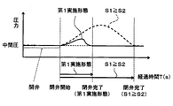
- the drawing It is a typical sectional view of the compressor of a 1st embodiment. It is an expanded sectional view of the backflow prevention structure of a 1st embodiment. It is explanatory drawing for demonstrating the response improvement effect of the backflow prevention structure of 1st Embodiment. It is explanatory drawing for demonstrating the noise reduction effect of the backflow prevention structure of 2nd Embodiment.
- FIGS. 1 A first embodiment of the present disclosure will be described with reference to FIGS.
- the compressor 1 having the backflow prevention structure 300 of the present disclosure is applied to a heat pump cycle 100 that heats hot water using a heat pump hot water supply device.
- the up and down arrows in FIG. 1 indicate the up and down directions in a state where the compressor 1 is mounted on the heat pump type hot water heater.
- the heat pump cycle 100 is configured as a gas injection cycle (economizer-type refrigeration cycle) in which an intermediate-pressure gas-phase refrigerant of the cycle is merged with a refrigerant in the pressurization process in the compression chamber 15 of the compressor 1. More specifically, the heat pump cycle 100 includes a compressor 1, a water-refrigerant heat exchanger 2, a first expansion valve 3, a gas-liquid separator 4, a second expansion valve 5, an outdoor heat, as shown in FIG. It has an exchange 6 and the like.
- the water-refrigerant heat exchanger 2 is a heating heat exchanger that heats hot water by exchanging heat between the refrigerant discharged from the discharge port 40a of the compressor 1 and the hot water.
- the first expansion valve 3 is high-stage decompression means for decompressing the high-pressure refrigerant flowing out of the water-refrigerant heat exchanger 2 until it becomes intermediate-pressure refrigerant, and operates according to a control signal output from a control device (not shown). Is an electric expansion valve controlled.
- the gas-liquid separator 4 is a gas-liquid separating means for separating the gas-liquid of the intermediate pressure refrigerant decompressed by the first expansion valve 3.
- the second expansion valve 5 is a low-stage decompression unit that decompresses the intermediate-pressure liquid-phase refrigerant flowing out from the liquid-phase refrigerant outlet of the gas-liquid separator 4 until it becomes a low-pressure refrigerant.
- the outdoor heat exchanger 6 is a heat absorption heat exchanger that evaporates the low-pressure refrigerant decompressed by the second expansion valve 5 by exchanging heat with the outside air.
- a suction port 30a of the compressor 1 is connected to the refrigerant outlet side of the outdoor heat exchanger 6, and an intermediate pressure inflow port (inflow port) 30b of the compressor 1 is connected to a gas phase refrigerant outlet of the gas-liquid separator 4. Is connected. Therefore, in this embodiment, the intermediate-pressure gas-phase refrigerant separated by the gas-liquid separator 4 is injected into the refrigerant in the pressurizing process in the compression chamber 15 of the compressor 1.
- the refrigerant is adopted as the refrigerant, and the pressure of the high-pressure side refrigerant in the cycle from the discharge port of the compressor 1 to the inlet side of the first expansion valve 3 is equal to or higher than the critical pressure. It constitutes a supercritical refrigeration cycle. Furthermore, the refrigerant is mixed with oil (refrigeration oil) that lubricates each sliding portion inside the compressor 1, and a part of this oil circulates in the cycle together with the refrigerant.
- oil refrigeration oil
- the heat pump type hot water heater is a hot water storage tank for storing hot water heated by the water-refrigerant heat exchanger 2, a hot water supply between the hot water storage tank and the water-refrigerant heat exchanger 2.
- a hot water circulation circuit for circulating water a water pump (none of which is shown) and the like that are arranged in the hot water circulation circuit and pump the hot water.
- the compressor 1 sucks, compresses and discharges a refrigerant that is a compression target fluid, an electric motor unit (electric motor unit) 20 that drives the compression mechanism unit 10, the compression mechanism unit 10, and the electric motor unit 20. And an oil separator 40 that separates oil from the high-pressure refrigerant that is disposed outside the housing 30 and is compressed by the compression mechanism unit 10.
- the compressor 1 includes a compression mechanism unit in which a drive shaft (shaft) 25 that transmits a rotational driving force from the electric motor unit 20 to the compression mechanism unit 10 extends in a vertical direction (vertical direction).
- a drive shaft (shaft) 25 that transmits a rotational driving force from the electric motor unit 20 to the compression mechanism unit 10 extends in a vertical direction (vertical direction).
- 10 and the electric motor unit 20 are configured in a so-called vertical placement type in which they are arranged in the vertical direction. More specifically, in this embodiment, the compression mechanism unit 10 is disposed below the electric motor unit 20.
- the housing 30 includes a cylindrical member 31 whose central axis extends in the vertical direction, a bowl-shaped upper lid member 32 that blocks the upper end portion of the cylindrical member 31, and a bowl-shaped lower lid member 33 that blocks the lower end portion of the cylindrical member 31. These are integrally joined to form a sealed container structure.
- the cylindrical member 31, the upper lid member 32, and the lower lid member 33 are all made of iron, and these are joined by welding.
- the housing 30 is supplied with a suction port 30a through which the low-pressure refrigerant flowing out of the outdoor heat exchanger 6 is sucked into the compression mechanism 10, and an intermediate-pressure gas-phase refrigerant flowing out from the gas-phase refrigerant outlet of the gas-liquid separator 4.
- the intermediate pressure inflow port (inflow port) 30b that merges with the refrigerant in the compression process in the compression chamber 15 of the compression mechanism unit 10 and the high-pressure refrigerant discharged from the compression mechanism unit 10 are disposed outside the housing 30.
- a refrigerant outlet and the like (not shown) for flowing out toward the oil separator 40 are formed.
- the electric motor unit 20 includes a coil stator 21 that forms a stator and a rotor 22 that forms a rotor.
- a shaft 25 is fixed to the shaft center hole of the rotor 22 by press-fitting. Therefore, when electric power is supplied from the control device to the coils of the coil stator 21 and a rotating magnetic field is generated, the rotor 22 and the shaft 25 rotate together.
- the shaft 25 is formed in a substantially cylindrical shape, and both end portions thereof are rotatably supported by a first bearing portion 26 and a second bearing portion 27 each formed by a sliding bearing. Further, an oil supply passage 25 a for supplying oil to the sliding portion between the outer surface of the shaft 25 and the first and second bearing portions 26 and 27 is formed inside the shaft 25.
- the first bearing portion 26 is formed in the middle housing 28 that divides the space in the housing 30 into an arrangement space for the electric motor portion 20 and an arrangement space for the compression mechanism portion 10, and the lower end side of the shaft 25 (the compression mechanism portion 10 Side). Further, the second bearing portion 27 is fixed to the cylindrical member 31 of the housing 30 via an interposed member, and supports the upper end side (the opposite side of the compression mechanism portion 10) of the shaft 25.
- the compression mechanism unit 10 includes a scroll type compression mechanism including a movable scroll 11 and a fixed scroll 12 each having a tooth portion formed in a spiral shape.
- the movable scroll 11 is disposed below the middle housing 28 described above, and the fixed scroll 12 is disposed below the movable scroll 11.
- the movable scroll 11 and the fixed scroll 12 have disk-like substrate portions 111 and 121, respectively, and both the substrate portions 111 and 121 are arranged to face each other in the vertical direction. Further, the outer peripheral side of the substrate portion 121 of the fixed scroll 12 is fixed to the cylindrical member 31 of the housing 30.
- a cylindrical boss portion 113 into which the lower end portion of the shaft 25 is inserted is formed at the center portion on the upper surface side of the substrate portion 111 of the movable scroll 11.
- the lower end portion of the shaft 25 is an eccentric portion 25 b that is eccentric with respect to the rotation center of the shaft 25. Accordingly, the eccentric portion 25 b of the shaft 25 is inserted on the upper surface side of the substrate portion 111 of the movable scroll 11.
- a rotation prevention mechanism (not shown) for preventing the movable scroll 11 from rotating around the eccentric portion 25b is provided. For this reason, when the shaft 25 rotates, the movable scroll 11 revolves (turns) around the center of rotation of the shaft 25 without rotating around the eccentric portion 25b.
- the movable scroll 11 is formed with a spiral tooth portion 112 protruding from the substrate portion 111 toward the fixed scroll 12 side.
- the fixed scroll 12 is formed with a spiral tooth portion 122 that protrudes from the substrate portion 121 toward the movable scroll 11 side and meshes with the tooth portion 112 of the movable scroll 11.
- compression chambers 15 move while reducing the volume from the outer peripheral side to the center side by the revolving motion of the movable scroll 11. Accordingly, the suction port 30a communicates with the compression chamber 15 positioned on the outermost peripheral side. Further, the intermediate pressure inflow port 30b communicates with the compression chamber 15 positioned at an intermediate position in the process of moving from the outermost peripheral side to the center side.
- the suction refrigerant passage extending from the suction port 30a to the compression chamber 15 positioned on the outermost peripheral side, and the injection passage extending from the intermediate pressure inflow port 30b to the compression chamber 15 positioned at the intermediate position.
- These refrigerant passages are all formed inside the substrate portion 121 of the fixed scroll 12.
- a reverse flow prevention structure 300 for preventing the refrigerant from flowing back from the compression chamber 15 side to the intermediate pressure inflow port 30b side is provided in the refrigerant passage from the intermediate pressure inflow port 30b to the compression chamber 15 at the intermediate position. ing. The detailed configuration of the backflow prevention structure 300 will be described later.
- a discharge hole 123 through which the refrigerant compressed in the compression chamber 15 is discharged is formed at the center of the substrate 121 on the fixed scroll 12 side. Further, a discharge chamber 124 communicating with the discharge hole 123 is formed below the discharge hole 123.
- the discharge chamber 124 is provided with a reed valve that forms a check valve that prevents the refrigerant from flowing backward from the discharge chamber 124 side to the compression chamber 15 side, and a stopper 16 that restricts the maximum opening of the reed valve.
- a refrigerant passage (not shown) that leads from the discharge chamber 124 to the refrigerant outlet formed in the housing 30 is formed inside the housing 30.
- a refrigerant inlet 40b of the oil separator 40 is connected to the refrigerant outlet.
- the oil separator 40 includes a cylindrical member 41 extending in the vertical direction, and the refrigerant pressurized by the compression mechanism unit 10 is swirled in a space formed therein, and the gas phase refrigerant and the oil are subjected to centrifugal force. And isolate.
- the high-pressure gas-phase refrigerant separated by the oil separator 40 flows out from the discharge port 40a formed on the upper side of the oil separator 40 to the water-refrigerant heat exchanger 2 side.
- the oil separated by the oil separator 40 is stored in a lower portion of the oil separator 40, and is further connected to the compression mechanism 10 and the shaft 25 in the housing 30 via the oil passage (not shown) and the first.
- the second bearing portions 26 and 27 are supplied to a sliding portion and the like.
- the intermediate pressure inflow port 30b communicates with the compression chamber 15 positioned at an intermediate position in the process of moving from the outermost peripheral side to the center side.
- the intermediate pressure gas phase refrigerant on the intermediate pressure inflow port 30b side when the pressure P2 of the intermediate pressure gas phase refrigerant on the intermediate pressure inflow port 30b side is higher than the refrigerant pressure P1 on the compression chamber 15 side, the intermediate pressure gas phase refrigerant can be injected into the compression chamber 15. However, if the refrigerant pressure P1 on the compression chamber 15 side becomes higher than the pressure P2 of the intermediate-pressure gas-phase refrigerant on the intermediate pressure inflow port 30b side, the refrigerant flows backward from the compression chamber 15 side to the intermediate pressure inflow port 30b side. .
- the backflow prevention structure 300 includes a check valve chamber 301 formed in the refrigerant passage for injection, a free valve 302 that is displaced in the check valve chamber 301 to open and close the refrigerant passage for injection,
- the case 303 is arranged in the stop valve chamber 301 and accommodates a free valve 302.
- the check valve chamber 301 is formed as a substantially cylindrical space, and is arranged so that its central axis extends in the horizontal direction. Further, a compression chamber side passage 400 that allows the check valve chamber 301 and the compression chamber 15 to communicate with each other on the bottom surface on one end side in the axial direction of the cylindrical space forming the check valve chamber 301 (the central axis side of the compressor 1). Is connected.
- the case 303 is composed of a casing part 303a and a stopper part 303b formed in a substantially cylindrical shape with iron (specifically, S45C).
- the casing portion 303 a is press-fitted and fixed in the check valve chamber 301 with its central axis disposed coaxially with the check valve chamber 301.
- the stopper portion 303b is press-fitted and fixed in the casing portion 303a in a state where the central axis thereof is disposed coaxially with the casing portion 303a.
- a bottom surface 303c that abuts when the free valve 302 is displaced to the side that opens the injection refrigerant passage is provided on one axial end side of the casing portion 303a.
- a communication hole 303d for communicating the internal space of the case 303 and the compression chamber side passage 400 is formed in the bottom surface 303c.
- FIG. 2 illustrates a state in which the free valve 302 is in contact with the contact portion 303e and the refrigerant passage for injection is closed.
- the internal space of the stopper portion 303b forms a part of the inflow port side passage 401 that allows the check valve chamber 301 and the intermediate pressure inflow port 30b to communicate with each other.
- the free valve 302 is formed in a substantially cylindrical shape with copper (specifically, C3604BD), and can slide in the central axis direction within the case 303 in a state where the central axis is arranged coaxially with the case 303. Are arranged.
- the outer diameter dimension of the free valve 302 and the inner diameter dimension of the casing portion 303a of the case 303 have a dimensional relationship of clearance gaps.
- the free valve 302 includes an axial hole 302a extending in the axial direction, a radial hole 302b extending in the radial direction, and a groove 302c formed in a cylindrical peripheral side surface.
- a valve-side passage 302d that allows the refrigerant to flow when it is opened is formed.
- the passage cross-sectional area S1 of the valve-side passage 302d is the minimum passage area of the refrigerant passage for injection
- the passage cross-sectional area S2 of the compression chamber-side passage 400 is the maximum passage area of the refrigerant passage for injection.
- the flow rate of the refrigerant flowing through the refrigerant passage for injection is determined by the passage sectional area S1 of the valve side passage 302d, which is the minimum passage area.
- S1 needs to be equal to or larger than the cross-sectional area of the passage through which a refrigerant having a flow rate necessary for injection can flow, as shown in Formula F2 below.
- the low-pressure refrigerant that has flowed out of the outdoor heat exchanger 6 flows into the compression chamber 15 that is positioned on the outermost peripheral side and communicates with the suction port 30a through the suction port 30a.
- the compression chamber 15 into which the low-pressure refrigerant has flowed moves to a position communicating with the intermediate pressure inflow port 30b while reducing its volume.
- the refrigerant passage for injection is opened, and the intermediate-pressure gas-phase refrigerant flowing from the intermediate pressure inflow port 30b into the check valve chamber 301 through the inflow port side passage 401 is formed in the inner space of the stopper 303b ⁇ the free valve 302.
- the flow then flows in the order of the valve-side passage 302d ⁇ the communication hole 303d of the casing portion 303a ⁇ the compression chamber-side passage 400, and is injected into the compression chamber 15.
- the shaft 25 rotates to reduce the volume of the compression chamber 15 and the refrigerant pressure P1 on the compression chamber 15 side exceeds the pressure P2 of the intermediate-pressure gas-phase refrigerant on the intermediate pressure inflow port 30b side, the refrigerant on the compression chamber 15 side. Due to the pressure difference between the pressure P1 and the refrigerant pressure P2 on the intermediate pressure inflow port 30b side, the free valve 302 of the backflow prevention structure 300 is displaced to the other end side of the check valve chamber 301 (the contact portion 303e side of the stopper portion 303b). To do.
- the refrigerant passage for injection is closed, and the refrigerant is prevented from flowing backward from the compression chamber 15 side to the intermediate pressure inflow port 30b side.
- the shaft 25 rotates and the compression chamber 15 moves toward the center and communicates with the discharge hole 123 of the fixed scroll 12
- the high-pressure refrigerant compressed in the compression chamber 15 is discharged through the oil separator 40 to the discharge port 40 a. From the water-refrigerant heat exchanger 2 side.
- the compressor 1 of the present embodiment operates as described above, and exhibits a function of sucking, compressing and discharging the refrigerant in the heat pump cycle 100. Further, in the backflow prevention structure 300 of the compressor 1 of the present embodiment, the free valve 302 is displaced by the differential pressure between the refrigerant pressure P1 on the compression chamber 15 side and the refrigerant pressure P2 on the intermediate pressure inflow port 30b side, so that the refrigerant is Backflow from the compression chamber 15 side to the intermediate pressure inflow port 30b side can be prevented.
- the passage sectional area S1 of the valve side passage 302d is smaller than the passage sectional area S2 of the compression chamber side passage 400.
- the resistance can be increased.
- the differential pressure between the refrigerant pressure P1 on the compression chamber 15 side and the refrigerant pressure P2 on the intermediate pressure inflow port 30b side is less likely to be reduced, and the responsiveness of the free valve 302 that is displaced by the differential pressure can be improved.
- the check valve chamber 301 and the free valve 302 are each formed in a cylindrical shape and the central axes are arranged coaxially with each other, so that the backflow prevention with improved responsiveness is adopted.
- the structure can be formed very easily.
- the free valve 302 and the case 303 can be integrated (modularized) by press-fitting and fixing the stopper portion 303b with the free valve 302 fitted into the casing portion 303a. Therefore, the backflow prevention structure 300 can be easily assembled to the compressor 1 (more specifically, the substrate portion 121 of the fixed scroll 12).
- the case 303 is formed of iron (specifically, S45C) and the free valve 302 is formed of copper (specifically, C3604BD) has been described.
- a damping steel plate is adopted as the material of 303.
- Other configurations and operations are the same as those in the first embodiment.
- the impact sound generated when the free valve 302 is displaced and collides with the bottom surface 303c of the casing portion 303a or the contact portion 303e of the stopper portion 303b. Will increase, and the operating noise of the backflow prevention structure will increase.
- the free valve 302 is made of resin and the case 303 is made of iron, there is a 16% noise reduction effect with respect to the first embodiment.
- the fixed scroll 12 constituting the compression mechanism needs to be formed of a material having relatively high strength and wear resistance (for example, carbon steel), it is not preferable that the fixed scroll 12 is formed of a damping steel plate. Therefore, modularizing the backflow prevention structure 300 as in the present embodiment is also effective in that the backflow prevention structure 300 using the damping steel plate can be easily applied to the compressor 1.
- the compression mechanism unit 10 is not limited thereto.
- a reciprocating type compression mechanism or a rotary type compression mechanism that reduces the volume of a compression chamber that compresses the fluid to be compressed by displacement of the movable member may be used.
- the free valve 302 is formed of a substantially cylindrical member, but the shape of the free valve 302 is not limited to this. For example, it may be formed in a truncated cone shape, a spherical shape, or the like. Further, the free valve 302 receives a load from a positioning spring or the like as long as it operates by a differential pressure between the refrigerant pressure P1 on the compression chamber 15 side and the refrigerant pressure P2 on the intermediate pressure inflow port 30b side. May be.
- valve side passage 302d formed in the free valve 302 is formed using a hole or the like extending in the axial direction or the radial direction of the free valve 302 . It is not limited to this.
- the valve side passage 302d is formed by a notch surface formed by scraping off a part of the cylindrical peripheral side surface. Also good.
- the configuration of the backflow prevention structure 300 is not limited thereto. That is, the configuration is such that the casing portion 303 a is abolished and the stopper portion 303 b is press-fitted and fixed in the check valve chamber 301 in a state where the free valve 302 is directly inserted into the check valve chamber 301 formed in the fixed scroll 12. Also good.
- the backflow prevention structure 300 is applied to prevent the backflow of the refrigerant from the compression chamber 15 to the intermediate pressure inflow port 30b side.
- the present invention may be applied to prevent the refrigerant from flowing backward from 15 to the suction port 30a side.
Landscapes
- Engineering & Computer Science (AREA)
- General Engineering & Computer Science (AREA)
- Mechanical Engineering (AREA)
- Physics & Mathematics (AREA)
- Thermal Sciences (AREA)
- Applications Or Details Of Rotary Compressors (AREA)
- Compressor (AREA)
- Rotary Pumps (AREA)
Abstract
La présente invention se rapporte à une structure de protection contre le reflux qui est appliquée à un compresseur (1) dans lequel se trouve un orifice d'entrée (30b) par lequel un fluide à comprimer s'écoule jusque dans une chambre de compression (15), et qui empêche le reflux du fluide depuis le côté chambre de compression (15) vers le côté orifice d'entrée (30b). La structure de protection contre le reflux est pourvue d'une chambre à clapet anti-retour (301) qui est formée dans un passage de fluide partant de l'orifice d'entrée (30b) à la chambre de compression (15), et d'un clapet libre (302) qui est déplacé dans la chambre à clapet anti-retour (301) pour ouvrir et fermer le passage de fluide. Le clapet libre (302) est déplacé par une pression différentielle entre une pression de fluide (P1) sur le côté chambre de compression (15) et une pression de fluide (P2) sur le côté orifice d'entrée (30b), un passage (302d) côté clapet par lequel le fluide s'écoule lorsque le clapet libre (302) ouvre le passage de fluide est formé dans le clapet libre (302) et la surface de section de passage (S1) du passage (302d) côté clapet est plus petite que la surface de section de passage (S2) d'un passage (400) côté chambre de compression reliant la chambre à clapet anti-retour (301) et la chambre de compression (15).
Applications Claiming Priority (2)
| Application Number | Priority Date | Filing Date | Title |
|---|---|---|---|
| JP2012-118545 | 2012-05-24 | ||
| JP2012118545A JP6059452B2 (ja) | 2012-05-24 | 2012-05-24 | 圧縮機の逆流防止構造 |
Publications (1)
| Publication Number | Publication Date |
|---|---|
| WO2013175708A1 true WO2013175708A1 (fr) | 2013-11-28 |
Family
ID=49623423
Family Applications (1)
| Application Number | Title | Priority Date | Filing Date |
|---|---|---|---|
| PCT/JP2013/002692 Ceased WO2013175708A1 (fr) | 2012-05-24 | 2013-04-22 | Structure de protection contre le reflux pour compresseur |
Country Status (2)
| Country | Link |
|---|---|
| JP (1) | JP6059452B2 (fr) |
| WO (1) | WO2013175708A1 (fr) |
Cited By (1)
| Publication number | Priority date | Publication date | Assignee | Title |
|---|---|---|---|---|
| WO2022027852A1 (fr) * | 2020-08-06 | 2022-02-10 | 艾默生环境优化技术(苏州)有限公司 | Ensemble manchon d'injection de vapeur améliorée et compresseur |
Families Citing this family (2)
| Publication number | Priority date | Publication date | Assignee | Title |
|---|---|---|---|---|
| CN110080981B (zh) * | 2019-05-24 | 2024-06-18 | 珠海格力节能环保制冷技术研究中心有限公司 | 压缩机及具有其的制冷循环装置 |
| KR102619531B1 (ko) * | 2021-12-20 | 2023-12-29 | 엘지전자 주식회사 | 스크롤압축기 |
Citations (3)
| Publication number | Priority date | Publication date | Assignee | Title |
|---|---|---|---|---|
| JPH03182681A (ja) * | 1989-12-12 | 1991-08-08 | Nippondenso Co Ltd | 燃料噴射ノズル |
| JP2002243312A (ja) * | 2001-02-14 | 2002-08-28 | Tgk Co Ltd | 膨張弁用防音カバー |
| JP2003148350A (ja) * | 2001-10-30 | 2003-05-21 | Lg Electronics Inc | 圧縮機の吸入バルブアセンブリー |
-
2012
- 2012-05-24 JP JP2012118545A patent/JP6059452B2/ja not_active Expired - Fee Related
-
2013
- 2013-04-22 WO PCT/JP2013/002692 patent/WO2013175708A1/fr not_active Ceased
Patent Citations (3)
| Publication number | Priority date | Publication date | Assignee | Title |
|---|---|---|---|---|
| JPH03182681A (ja) * | 1989-12-12 | 1991-08-08 | Nippondenso Co Ltd | 燃料噴射ノズル |
| JP2002243312A (ja) * | 2001-02-14 | 2002-08-28 | Tgk Co Ltd | 膨張弁用防音カバー |
| JP2003148350A (ja) * | 2001-10-30 | 2003-05-21 | Lg Electronics Inc | 圧縮機の吸入バルブアセンブリー |
Cited By (1)
| Publication number | Priority date | Publication date | Assignee | Title |
|---|---|---|---|---|
| WO2022027852A1 (fr) * | 2020-08-06 | 2022-02-10 | 艾默生环境优化技术(苏州)有限公司 | Ensemble manchon d'injection de vapeur améliorée et compresseur |
Also Published As
| Publication number | Publication date |
|---|---|
| JP6059452B2 (ja) | 2017-01-11 |
| JP2013245585A (ja) | 2013-12-09 |
Similar Documents
| Publication | Publication Date | Title |
|---|---|---|
| CN104105878B (zh) | 压缩机 | |
| US20140134030A1 (en) | Compressor valve system and assembly | |
| WO2013145713A1 (fr) | Compresseur | |
| TW200401080A (en) | Dual volume-ratio scroll machine | |
| JP2013148043A (ja) | 差圧弁及び差圧弁を備える電動圧縮機 | |
| US20200173436A1 (en) | Motor driven compressor apparatus | |
| US9803643B2 (en) | Scroll-type compressor | |
| JP6460595B2 (ja) | 圧縮機 | |
| JP6130771B2 (ja) | 圧縮機および冷凍サイクル装置 | |
| JP6059452B2 (ja) | 圧縮機の逆流防止構造 | |
| JP6507557B2 (ja) | 圧縮機 | |
| JP6302428B2 (ja) | シリンダ回転型圧縮機 | |
| JP6285816B2 (ja) | 圧縮機 | |
| JP2018127903A (ja) | 圧縮機 | |
| JP6130759B2 (ja) | 圧縮機 | |
| CN110886623B (zh) | 涡旋式膨胀机 | |
| JP2018123812A (ja) | 圧縮機 | |
| JP6093676B2 (ja) | 圧縮機 | |
| JP2011163227A (ja) | 圧縮機 | |
| JP6399637B2 (ja) | 圧縮機 | |
| JP2014083520A (ja) | オイルセパレータ | |
| JP5304679B2 (ja) | 圧縮機 | |
| JP2011127462A (ja) | 圧縮機 | |
| JP6915398B2 (ja) | 圧縮機 | |
| JP2019002611A (ja) | 冷凍サイクル装置 |
Legal Events
| Date | Code | Title | Description |
|---|---|---|---|
| 121 | Ep: the epo has been informed by wipo that ep was designated in this application |
Ref document number: 13793766 Country of ref document: EP Kind code of ref document: A1 |
|
| NENP | Non-entry into the national phase |
Ref country code: DE |
|
| 122 | Ep: pct application non-entry in european phase |
Ref document number: 13793766 Country of ref document: EP Kind code of ref document: A1 |