WO2013175871A1 - Procédé de détection d'usure irrégulière sur un pneumatique et dispositif de détection d'usure irrégulière sur un pneumatique - Google Patents
Procédé de détection d'usure irrégulière sur un pneumatique et dispositif de détection d'usure irrégulière sur un pneumatique Download PDFInfo
- Publication number
- WO2013175871A1 WO2013175871A1 PCT/JP2013/060274 JP2013060274W WO2013175871A1 WO 2013175871 A1 WO2013175871 A1 WO 2013175871A1 JP 2013060274 W JP2013060274 W JP 2013060274W WO 2013175871 A1 WO2013175871 A1 WO 2013175871A1
- Authority
- WO
- WIPO (PCT)
- Prior art keywords
- tire
- acceleration
- uneven wear
- frequency band
- band value
- Prior art date
- Legal status (The legal status is an assumption and is not a legal conclusion. Google has not performed a legal analysis and makes no representation as to the accuracy of the status listed.)
- Ceased
Links
Images



Classifications
-
- B—PERFORMING OPERATIONS; TRANSPORTING
- B60—VEHICLES IN GENERAL
- B60C—VEHICLE TYRES; TYRE INFLATION; TYRE CHANGING; CONNECTING VALVES TO INFLATABLE ELASTIC BODIES IN GENERAL; DEVICES OR ARRANGEMENTS RELATED TO TYRES
- B60C11/00—Tyre tread bands; Tread patterns; Anti-skid inserts
- B60C11/24—Wear-indicating arrangements
- B60C11/243—Tread wear sensors, e.g. electronic sensors
-
- B—PERFORMING OPERATIONS; TRANSPORTING
- B60—VEHICLES IN GENERAL
- B60C—VEHICLE TYRES; TYRE INFLATION; TYRE CHANGING; CONNECTING VALVES TO INFLATABLE ELASTIC BODIES IN GENERAL; DEVICES OR ARRANGEMENTS RELATED TO TYRES
- B60C11/00—Tyre tread bands; Tread patterns; Anti-skid inserts
- B60C11/24—Wear-indicating arrangements
- B60C11/246—Tread wear monitoring systems
-
- G—PHYSICS
- G01—MEASURING; TESTING
- G01M—TESTING STATIC OR DYNAMIC BALANCE OF MACHINES OR STRUCTURES; TESTING OF STRUCTURES OR APPARATUS, NOT OTHERWISE PROVIDED FOR
- G01M17/00—Testing of vehicles
- G01M17/007—Wheeled or endless-tracked vehicles
- G01M17/02—Tyres
- G01M17/025—Tyres using infrasonic, sonic or ultrasonic vibrations
-
- G—PHYSICS
- G01—MEASURING; TESTING
- G01P—MEASURING LINEAR OR ANGULAR SPEED, ACCELERATION, DECELERATION, OR SHOCK; INDICATING PRESENCE, ABSENCE, OR DIRECTION, OF MOVEMENT
- G01P15/00—Measuring acceleration; Measuring deceleration; Measuring shock, i.e. sudden change of acceleration
Definitions
- the present invention relates to a method and apparatus for detecting uneven wear at the end of a shoulder portion of a tire tread from an output signal of an acceleration sensor disposed on the inner surface side of the tire tread.
- the tire wears on the tread surface due to friction with the road surface during running. From the standpoint of tire performance, it is desirable that the tread surface wear evenly, so that the ground contact shape does not change significantly. Therefore, the wear amount may be different between the center portion and the shoulder portion of the tire tread. If these uneven wears accumulate, the tire shoulder end will end up with a significantly worn tire.
- a tire in which such uneven wear is piled up is referred to as uneven wear tire with respect to a normal wear tire that is a tire with a uniformly worn tread surface. If you continue to use tires with extreme uneven wear, the tire's original performance cannot be achieved. In particular, in a studless tire, there is a problem that a lack of grip on the road surface is likely to occur. Further, since the unevenly worn tire deviates from the ideal state of the ground contact shape of the tire, the fuel consumption performance is also lower than that of a normally worn tire in which the tread surface is evenly worn.
- an acceleration sensor installed at the center of the tire inner liner portion in the width direction of the tire is used.
- the acceleration waveforms in both areas are extracted and analyzed, and the frequency band value that is the magnitude of the acceleration in the specific frequency band is calculated from the obtained frequency spectrum. By comparing the calculated frequency band value with a preset threshold, and detects the degree of
- a detector made of a magnetic material or conductive rubber is embedded in the groove of the tire tread or inside the tread rubber, and a sensor is arranged on the vehicle body side.
- a method of estimating the wear of the tire because the detection body wears and the detection signal of the sensor changes for example, refer to Patent Document 2), or a odor gas or a colored gas is inserted into the tire tread in advance.
- a method of recognizing that the tire is worn by the wear progressing and the gas-filled portion being exposed to the air and released into the odorous gas or colored gas air has been proposed.
- Patent Document 1 Although the method described in Patent Document 1 is effective for detecting the overall progress of wear from a new tire, it can accurately detect local wear of the shoulder portion such as shoulder edge wear. Is not an effective method. Further, in the methods described in Patent Documents 2 and 3, foreign matter such as a magnetic material or gas is inserted into the tire tread, and therefore the location where the foreign matter is inserted becomes the core of failure, which may impair the durability of the tire. Concerned.
- the present invention has been made in view of conventional problems, and an object of the present invention is to provide a method and apparatus for accurately detecting shoulder edge wear without impairing the durability of a tire.
- the present invention relates to a tire uneven wear detection method for detecting uneven wear of a tire from an acceleration waveform detected using an acceleration sensor.
- FIG. 1 is a functional block diagram showing a configuration of a tire uneven wear detection device 10 in which 11 is an acceleration sensor, 12 is an acceleration waveform extracting means, 13 is an acceleration waveform separating means, 14 is a frequency analyzing means, and 15 is a frequency.
- Band value calculation means, 16 is storage means, and 17 is shoulder edge wear detection means.
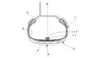
- the acceleration sensor 11 is arranged at the center of the tire width direction indicated by CL of the inner liner portion 2 of the tire 1 so that the detection direction is the tire radial direction. The tire radial acceleration acting on the inner surface of the center portion 4 is detected.
- the acceleration sensor 11 constitutes a sensor part 10A of the tire uneven wear detection device 10, and each means from the acceleration waveform extraction means 12 to the shoulder edge wear detection means 17 constitutes a storage / calculation part 10B.
- Each means constituting the storage / calculation unit 10B is constituted by, for example, computer software and is disposed on the vehicle body side (not shown).
- the storage means 16 is configured by a memory such as a RAM. Further, as a configuration for sending the output signal of the acceleration sensor 11 to the arithmetic unit 10B, for example, as shown in FIG. 2, a transmitter 11F is installed in the inner liner part 2 or the wheel 5, and the output signal of the acceleration sensor 11 is sent.
- the signal is amplified by an amplifier (not shown) and then transmitted to the arithmetic unit 10B arranged on the vehicle body side by radio.
- the arithmetic unit 10B arranged on the vehicle body side by radio.
- the acceleration waveform extracting means 12 is used when the tire radial acceleration in the vicinity of the tire contact surface in the center portion 4 from the signal representing the magnitude of the tire radial acceleration acting on the center portion 4 of the tire tread 3 output from the acceleration sensor 11.
- An acceleration waveform that is a series waveform is extracted.
- the acceleration waveform separating unit 13 separates and extracts a region acceleration waveform that is an acceleration waveform in the post-kick region from the acceleration waveform extracted by the acceleration waveform extracting unit 12.
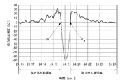
- FIG. 3 is a diagram illustrating an example of a radial acceleration waveform detected by the acceleration sensor 11, where the horizontal axis represents time [sec.] And the vertical axis represents the magnitude [G] of radial acceleration. In the radial acceleration waveform, as shown in FIG.
- the acceleration waveform separating means 13 determines the kicking point P k from the radial acceleration waveform. Then, an acceleration waveform in a later time region is extracted and sent to the frequency analysis means 14 as a region acceleration waveform.
- the acceleration waveform depression front region when the region acceleration waveform extracts an acceleration waveform in the time domain before the depression point P f, which may be the area acceleration waveform.
- the position of the depression point P f, and the position of the kicker point P k is two peaks appearing in acceleration differential waveform obtained by differentiating the radial acceleration waveform (edge peak kicking the leading edge peak) It is more accurate to obtain from the position.
- the frequency analysis means 14 performs an FFT process on a region acceleration waveform (time series waveform) that is an acceleration waveform in the post-kick region, and calculates a frequency spectrum of the region acceleration.
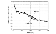
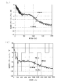
- FIG. 4 is a diagram illustrating an example of a frequency spectrum of region acceleration, where the horizontal axis represents frequency [Hz] and the vertical axis represents radial acceleration magnitude (acceleration spectrum level) [dB].
- the higher acceleration spectrum level is the data of tires where shoulder edge wear occurred (hereinafter referred to as uneven wear products), and the normal wear tires where the lower acceleration spectrum level has no uneven wear (Normally worn product) data.
- uneven wear products the data of tires where shoulder edge wear occurred
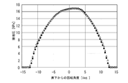
- FIG. 6 is a diagram showing the circumferential contact pressure distribution in the tire center 4 part, where the horizontal axis is the rotation angle [deg] from directly below (the contact center when viewed from the tire axial direction), and the vertical axis is the contact pressure [GPa. ].
- the rhombuses in the figure are data for normal wear products
- the triangles are data for uneven wear products.
- FIG. 7A is a frequency spectrum obtained by performing FFT processing on the acceleration waveform in the region before depression
- FIG. 7B is obtained by performing FFT processing on the frequency spectrum of tire radial acceleration in the continuous region including the contact surface.
- the acceleration spectrum in the region before stepping or the frequency spectrum of the acceleration waveform after kicking out is a continuous region including the ground plane.
- the difference between the acceleration spectrum level of the uneven wear product and the acceleration spectrum level of the normal wear product is larger than the frequency spectrum of the tire radial direction acceleration.
- the frequency band value calculating unit 15 calculates an acceleration spectrum level that is a vibration level in a specific frequency band of the frequency spectrum of the region acceleration, and sends the calculated value to the shoulder edge wear detecting unit 17 as a frequency band value T.
- the storage means 16 stores a reference frequency band value T 0 that is a frequency band value in a normal wear tire in which uneven wear has not occurred at the end of the shoulder portion that has been obtained in advance. As a tire (normally worn tire) for setting the reference band value, for example, in a laboratory test, until the tire is caused to travel under conditions that cause large uneven wear on the shoulder portion, and uneven wear occurs on the shoulder portion.
- the shoulder edge wear detection means 17 compares the frequency band value T calculated by the frequency band value calculation means 15 with the reference frequency band value T 0 and determines whether shoulder edge wear has occurred.
- the acceleration sensor 11 detects tire radial acceleration at the center portion 4 on the inner surface of the inner liner portion 2 that deforms as the tire tread 3 is deformed, and then transmits the detected tire radial acceleration data to the transmitter 11F.
- the arithmetic unit 10B extracts an acceleration waveform, which is a time-series waveform of tire radial acceleration near the tire contact surface, from the output signal of the acceleration sensor 11, and then extracts and extracts a region acceleration waveform from the acceleration waveform. Whether or not shoulder edge wear has occurred in the tire 1 is determined using the determined region acceleration waveform.
- a frequency band value T which is the magnitude of radial acceleration in a specific frequency band of the frequency spectrum of the area acceleration obtained by FFT processing of the area acceleration waveform, is calculated, and the frequency band value T is obtained in advance.
- a comparison is made with the reference frequency band value (frequency band value in normal wear tires) T 0 to determine whether or not shoulder edge wear has occurred.
- a determination method for example, it is determined that shoulder edge wear has occurred when the difference between the frequency band value T (dB) and the reference frequency band value T 0 (dB) exceeds a preset threshold value K. do it.
- the partial wear at the end of the tire shoulder was detected using the area acceleration waveform, which is the acceleration waveform excluding the acceleration waveform of the ground contact portion with little information that can distinguish between normal wear state and uneven wear state.
- the accuracy of detecting uneven wear can be improved.
- the occurrence of uneven wear can be detected by one acceleration sensor 11, not only the system can be simplified, but also shoulder uneven wear can be detected without adversely affecting durability.
- the arrangement position of the acceleration sensor 11 is set to the center in the width direction of the tire tread 3, it is possible to detect whether the shoulder on either the vehicle body side or the non-vehicle body side is unevenly worn.
- the tire is caused to run under conditions that cause large uneven wear on the shoulder portion, and uneven wear occurs on the shoulder portion. Measure the time (or distance) until wear, and use tires that are worn by running the tire for the same time (or distance) as the time (or distance) in a state where uneven wear is unlikely to occur. do it. Since the groove depth of the tire in which the wear of the tire tread 3 has progressed is shallow, the block rigidity is higher than that of a new tire, and as a result, the generation area of the out-of-ground surface high frequency is different from that of the new tire. . Therefore, the detection accuracy is improved by using the frequency band value T 0 of the normally worn tire as in this example.
- tire radial acceleration is used, but tire circumferential acceleration or tire width acceleration may be used.
- the output signal of the acceleration sensor 11 includes the natural vibration frequency component of the tread block. Therefore, compared with the case where the tire radial acceleration is used, the detection accuracy of uneven wear is improved. Decreases slightly. Further, when the tire width direction acceleration is used, the output signal of the acceleration sensor 11 becomes smaller than the tire radial direction acceleration signal, so that the detection accuracy of uneven wear is lowered.
- the frequency band value is obtained from the frequency spectrum obtained by subjecting the extracted region acceleration waveform to the FFT processing. The frequency component of 800 Hz to 1500 Hz obtained by passing the region acceleration waveform through the bandpass filter is obtained.
- a frequency band value may be obtained from an acceleration waveform including only
- the acceleration waveform in the area after kicking is extracted and used as the area acceleration waveform.
- the acceleration waveform in the area before stepping may be used as the area acceleration waveform.
- the acceleration waveforms of both the pre-stepping region and the post-pickup region are extracted, and from the stepping-side frequency band value T (f) and the kicking-side band value T (k) obtained using the respective region acceleration waveforms.
- the uneven wear at the end of the tire shoulder may be detected. Specifically, one of the frequency band values T (f) and T (k) increases by a predetermined value or more with respect to the reference frequency band values T 0 (f) and T (k) 0 obtained in advance. If it is, it may be determined that shoulder edge wear has occurred.
- Example 10 A test vehicle equipped with a test tire with an acceleration sensor placed in the tire width direction center of the inner liner part of the tire so that the detection direction is the tire radial direction is run at a speed of 40 km / hr to 80 km / hr.
- the storage / calculation unit that processes the output signal of the acceleration sensor is mounted on the vehicle body side, and the frequency spectrum of the region acceleration waveform is obtained.
- the tire size of the test tire is 315 / 80R22.5.
- three types of vehicles, “empty vehicle”, “half-loaded vehicle”, and “loaded vehicle”, were run as test vehicles, and the influence of the load was examined.
- the load of “empty vehicle” is 1.9 [t]
- the load of “half-load vehicle” is 2.4 [t]
- the load of “load vehicle” is 2.85 [t].
- the frequency spectrum is a frequency spectrum of the depression side region acceleration waveform (hereinafter referred to as the depression side spectrum) for each of the normal wear product and the uneven wear product in which the shoulder edge wear indicated by the symbol Z in FIG.
- the frequency spectrum of the kick-out area acceleration waveform (hereinafter referred to as kick-out spectrum) was obtained.
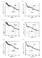
- FIG. 8 is a frequency spectrum obtained by running the test vehicle at a speed of 60 km / hr
- FIG. 9 is a frequency spectrum obtained when the test vehicle is run at 80 km / hr. 8 and 9, (a) is a stepped-side spectrum in which the load is “loading”, (b) is a kick-out side spectrum in which the load is “loading”, and (c) is a load in the “loading” spectrum.
- the acceleration spectrum level of the uneven wear product is higher than the acceleration spectrum level of the normal wear product in the 1000 Hz to 1500 Hz band, and in the kicking side spectrum, It can be seen that in the 800 Hz to 1200 Hz band, the acceleration spectrum level of the uneven wear product is higher than the acceleration spectrum level of the normal wear product.
- the kicking side spectrum can detect the shoulder edge wear even at a low speed and a low load. It can also be seen that the difference between the acceleration spectrum level of the uneven wear product and the acceleration spectrum level of the normal wear product increases as the load and speed increase. The frequency spectrum at a speed of 40 km / hr was omitted because the level difference between the normal wear product and the uneven wear product was small.
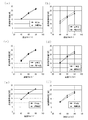
- FIG. 10 is a diagram showing the relationship between the speed and the frequency band value, where the circle is the frequency band value of the normal wear product and the triangle is the frequency band value of the uneven wear product. Also, (a) Fig. Shows the frequency band value of the tread side spectrum where the load is "loading”, (b) Fig. Shows the frequency band value of the kicking side spectrum where the load is "loading”, and (c) shows the figure. The frequency band value of the step-in spectrum with a load of “half-load vehicle”, (d) the figure shows the frequency band value of the kick-out spectrum with the load of “half-load vehicle”, and (e) the figure has a load of “empty vehicle”.
- FIG. 10 The frequency band value of the kick-out side spectrum whose load is “empty” is shown in FIG. FIG. 10 also shows that the frequency band value of the uneven wear product is higher than the frequency band value of the normal wear product. Moreover, it turns out that the frequency band value of a partial wear product is increasing rather than the frequency band value of a normal wear product similarly to the frequency spectrum shown in FIG.8 and FIG.9. Therefore, if the uneven wear at the end of the tire shoulder is detected from the magnitude of the frequency band value calculated from the area acceleration waveform, which is the acceleration waveform in the area before stepping or after kicking out, the accuracy of detecting uneven wear is improved. Confirmed to do.
Landscapes
- Physics & Mathematics (AREA)
- General Physics & Mathematics (AREA)
- Engineering & Computer Science (AREA)
- Mechanical Engineering (AREA)
- Tires In General (AREA)
- Length Measuring Devices With Unspecified Measuring Means (AREA)
Priority Applications (3)
| Application Number | Priority Date | Filing Date | Title |
|---|---|---|---|
| US14/390,690 US20150090023A1 (en) | 2012-05-24 | 2013-04-04 | Method and apparatus for detecting uneven wear on tire |
| EP13793840.3A EP2857227B1 (fr) | 2012-05-24 | 2013-04-04 | Procédé et dispositif de détection d'usure irrégulière sur un pneumatique |
| CN201380027158.1A CN104334375B (zh) | 2012-05-24 | 2013-04-04 | 轮胎不均匀磨损检测方法和轮胎不均匀磨损检测设备 |
Applications Claiming Priority (2)
| Application Number | Priority Date | Filing Date | Title |
|---|---|---|---|
| JP2012-118945 | 2012-05-24 | ||
| JP2012118945A JP5956250B2 (ja) | 2012-05-24 | 2012-05-24 | タイヤ偏摩耗検知方法及びタイヤ偏摩耗検知装置 |
Publications (1)
| Publication Number | Publication Date |
|---|---|
| WO2013175871A1 true WO2013175871A1 (fr) | 2013-11-28 |
Family
ID=49623575
Family Applications (1)
| Application Number | Title | Priority Date | Filing Date |
|---|---|---|---|
| PCT/JP2013/060274 Ceased WO2013175871A1 (fr) | 2012-05-24 | 2013-04-04 | Procédé de détection d'usure irrégulière sur un pneumatique et dispositif de détection d'usure irrégulière sur un pneumatique |
Country Status (5)
| Country | Link |
|---|---|
| US (1) | US20150090023A1 (fr) |
| EP (1) | EP2857227B1 (fr) |
| JP (1) | JP5956250B2 (fr) |
| CN (1) | CN104334375B (fr) |
| WO (1) | WO2013175871A1 (fr) |
Cited By (2)
| Publication number | Priority date | Publication date | Assignee | Title |
|---|---|---|---|---|
| JP2015102445A (ja) * | 2013-11-26 | 2015-06-04 | 株式会社ブリヂストン | タイヤ偏摩耗推定方法及びタイヤ偏摩耗推定装置 |
| CN108562446A (zh) * | 2018-04-25 | 2018-09-21 | 石家庄铁道大学 | 基于轴箱振动时频域特征车轮多边形检测方法及终端设备 |
Families Citing this family (21)
| Publication number | Priority date | Publication date | Assignee | Title |
|---|---|---|---|---|
| US20150057877A1 (en) | 2013-08-22 | 2015-02-26 | The Goodyear Tire & Rubber Company | Tire wear state estimation system utilizing cornering stiffness and method |
| US20180290501A1 (en) * | 2017-04-07 | 2018-10-11 | GM Global Technology Operations LLC | Methods and apparatus for determining remaining life of a tire based on road vibration data and tire tread groove depth |
| CN108087620B (zh) * | 2017-12-20 | 2019-03-15 | 重庆洛昂机械有限公司 | 用于安全阀门的检测装置 |
| CN108061648B (zh) * | 2017-12-20 | 2019-06-14 | 重庆洛昂机械有限公司 | 一种阀门的检测方法 |
| EP3779393B1 (fr) | 2018-05-10 | 2024-03-27 | Bridgestone Corporation | Système de prédiction d'usure de pneu, programme de prédiction d'usure de pneu, procédé de prédiction d'usure de pneu et structure de données |
| IT201800005906A1 (it) * | 2018-05-31 | 2019-12-01 | Sistema e metodo di rilevamento di danni a pneumatici | |
| JP7187214B2 (ja) * | 2018-08-28 | 2022-12-12 | 株式会社ブリヂストン | タイヤ状態検出システム、タイヤ状態検出方法及びタイヤ状態検出プログラム |
| JP6935812B2 (ja) * | 2018-12-13 | 2021-09-15 | 株式会社Soken | タイヤ摩耗検知装置 |
| JPWO2020129953A1 (ja) | 2018-12-17 | 2021-10-14 | アルプスアルパイン株式会社 | 複合圧電素子、タイヤ状態測定装置、タイヤセンサモジュール、タイヤセンサ装置、および圧電センサ |
| EP3946983B1 (fr) | 2019-04-01 | 2024-10-30 | Bridgestone Americas Tire Operations, LLC | Système et procédé de modélisation et de rétroaction de performances d'un pneu de véhicule |
| JP2020183901A (ja) * | 2019-05-08 | 2020-11-12 | 株式会社神戸製鋼所 | タイヤユニフォミティデータの補正方法、およびタイヤユニフォミティマシン |
| DE112021004471B4 (de) * | 2020-08-25 | 2025-07-17 | Alps Alpine Co., Ltd. | Reifenabnutzungsmesseinrichtung |
| CN116710297A (zh) * | 2020-12-30 | 2023-09-05 | 倍耐力轮胎股份公司 | 用于监测轮胎的状态的方法和系统 |
| EP4271575B1 (fr) * | 2020-12-30 | 2026-04-29 | Pirelli Tyre S.p.A. | Procédé et système de surveillance d'un état de pneu |
| DE102021203191A1 (de) * | 2021-03-30 | 2022-10-06 | Continental Reifen Deutschland Gmbh | Verfahren zur Bestimmung eines Abriebs eines Reifens |
| US12263704B2 (en) | 2021-12-06 | 2025-04-01 | The Goodyear Tire & Rubber Company | Tire irregular wear detection system and method |
| DE102022201283A1 (de) * | 2022-02-08 | 2023-08-10 | Continental Reifen Deutschland Gmbh | Verfahren zum Ermitteln von ungleichmäßigem Fahrzeugreifenverschleiß |
| DE102022201675A1 (de) * | 2022-02-17 | 2023-08-17 | Continental Reifen Deutschland Gmbh | Verfahren und Vorrichtung zur Ermittlung einer Profiltiefe eines Fahrzeugreifens |
| CN115179691A (zh) * | 2022-07-15 | 2022-10-14 | 江苏路必达物联网技术有限公司 | 一种轮胎偏磨的预警方法 |
| CN116087018B (zh) * | 2022-12-14 | 2024-01-30 | 常州市大成真空技术有限公司 | 一种涂布机的磨损检测方法 |
| DE102023208943A1 (de) | 2023-09-14 | 2025-03-20 | Continental Reifen Deutschland Gmbh | Verfahren zum Ermitteln eines ungleichmäßig abgenutzten Fahrzeugreifens und Verschleißermittlungsanordnung |
Citations (5)
| Publication number | Priority date | Publication date | Assignee | Title |
|---|---|---|---|---|
| JP2003214808A (ja) | 2002-01-21 | 2003-07-30 | Bridgestone Corp | タイヤの磨耗測定方法 |
| JP2005028950A (ja) | 2003-07-09 | 2005-02-03 | Yokohama Rubber Co Ltd:The | タイヤ摩耗検知方法と装置、及び空気入りタイヤ |
| JP2007153034A (ja) * | 2005-12-01 | 2007-06-21 | Toyota Motor Corp | タイヤ摩耗状態判定装置 |
| JP2009018667A (ja) | 2007-07-11 | 2009-01-29 | Bridgestone Corp | タイヤの摩耗検知方法及びタイヤの摩耗検知装置 |
| JP2009292283A (ja) * | 2008-06-04 | 2009-12-17 | Yokohama Rubber Co Ltd:The | タイヤの姿勢制御装置および方法 |
Family Cites Families (10)
| Publication number | Priority date | Publication date | Assignee | Title |
|---|---|---|---|---|
| EP1219515B1 (fr) * | 2000-06-23 | 2011-01-19 | Kabushiki Kaisha Bridgestone | Procede d'estimation de l'etat de marche d'un vehicule, dispositif d'estimation de l'etat de marche d'un vehicule, dispositif de commande de vehicule, et bandage de roue |
| CN1307064C (zh) * | 2002-03-28 | 2007-03-28 | 倍耐力轮胎公司 | 一种用于监测轮胎在机动车行驶期间状态的方法和系统 |
| JP5100095B2 (ja) * | 2006-11-29 | 2012-12-19 | 株式会社ブリヂストン | タイヤ摩耗量の推定方法及びタイヤ摩耗量推定装置 |
| US8371159B2 (en) * | 2007-07-11 | 2013-02-12 | Kabushiki Kaisha Bridgestone | Method for estimating the wear of a tire |
| EP2301769B1 (fr) * | 2008-06-25 | 2017-01-11 | Kabushiki Kaisha Bridgestone | Procédé et dispositif d évaluation d usure de pneumatique |
| TWI358154B (en) * | 2008-07-23 | 2012-02-11 | Wistron Neweb Corp | Flat antenna structure |
| JP5165603B2 (ja) * | 2009-01-09 | 2013-03-21 | 株式会社ブリヂストン | タイヤ走行状態推定方法、定常走行状態推定装置、タイヤ摩耗推定方法とその装置 |
| JP5412315B2 (ja) * | 2010-02-19 | 2014-02-12 | 株式会社ブリヂストン | タイヤ偏摩耗の推定方法 |
| JP5531265B2 (ja) * | 2010-10-12 | 2014-06-25 | パナソニック株式会社 | タイヤ状態検出装置およびタイヤ状態検出方法 |
| JP5898519B2 (ja) * | 2012-02-17 | 2016-04-06 | 株式会社ブリヂストン | タイヤ摩耗量推定方法及びタイヤ摩耗量推定装置 |
-
2012
- 2012-05-24 JP JP2012118945A patent/JP5956250B2/ja not_active Expired - Fee Related
-
2013
- 2013-04-04 US US14/390,690 patent/US20150090023A1/en not_active Abandoned
- 2013-04-04 WO PCT/JP2013/060274 patent/WO2013175871A1/fr not_active Ceased
- 2013-04-04 CN CN201380027158.1A patent/CN104334375B/zh not_active Expired - Fee Related
- 2013-04-04 EP EP13793840.3A patent/EP2857227B1/fr not_active Not-in-force
Patent Citations (5)
| Publication number | Priority date | Publication date | Assignee | Title |
|---|---|---|---|---|
| JP2003214808A (ja) | 2002-01-21 | 2003-07-30 | Bridgestone Corp | タイヤの磨耗測定方法 |
| JP2005028950A (ja) | 2003-07-09 | 2005-02-03 | Yokohama Rubber Co Ltd:The | タイヤ摩耗検知方法と装置、及び空気入りタイヤ |
| JP2007153034A (ja) * | 2005-12-01 | 2007-06-21 | Toyota Motor Corp | タイヤ摩耗状態判定装置 |
| JP2009018667A (ja) | 2007-07-11 | 2009-01-29 | Bridgestone Corp | タイヤの摩耗検知方法及びタイヤの摩耗検知装置 |
| JP2009292283A (ja) * | 2008-06-04 | 2009-12-17 | Yokohama Rubber Co Ltd:The | タイヤの姿勢制御装置および方法 |
Cited By (5)
| Publication number | Priority date | Publication date | Assignee | Title |
|---|---|---|---|---|
| JP2015102445A (ja) * | 2013-11-26 | 2015-06-04 | 株式会社ブリヂストン | タイヤ偏摩耗推定方法及びタイヤ偏摩耗推定装置 |
| WO2015079741A1 (fr) * | 2013-11-26 | 2015-06-04 | 株式会社ブリヂストン | Procédé d'estimation d'usure irrégulière de pneu et dispositif d'estimation d'usure irrégulière de pneu |
| US10286734B2 (en) | 2013-11-26 | 2019-05-14 | Bridgestone Corporation | Method and apparatus for estimating uneven tire wear |
| CN108562446A (zh) * | 2018-04-25 | 2018-09-21 | 石家庄铁道大学 | 基于轴箱振动时频域特征车轮多边形检测方法及终端设备 |
| CN108562446B (zh) * | 2018-04-25 | 2020-04-14 | 石家庄铁道大学 | 基于轴箱振动时频域特征车轮多边形检测方法及终端设备 |
Also Published As
| Publication number | Publication date |
|---|---|
| JP2013244807A (ja) | 2013-12-09 |
| US20150090023A1 (en) | 2015-04-02 |
| JP5956250B2 (ja) | 2016-07-27 |
| CN104334375B (zh) | 2017-06-30 |
| EP2857227A4 (fr) | 2016-01-13 |
| CN104334375A (zh) | 2015-02-04 |
| EP2857227B1 (fr) | 2021-01-06 |
| EP2857227A1 (fr) | 2015-04-08 |
Similar Documents
| Publication | Publication Date | Title |
|---|---|---|
| JP5956250B2 (ja) | タイヤ偏摩耗検知方法及びタイヤ偏摩耗検知装置 | |
| JP5806278B2 (ja) | タイヤ偏摩耗推定方法及びタイヤ偏摩耗推定装置 | |
| JP5898519B2 (ja) | タイヤ摩耗量推定方法及びタイヤ摩耗量推定装置 | |
| JP5620268B2 (ja) | タイヤ摩耗推定方法及びタイヤ摩耗推定装置 | |
| JP5902473B2 (ja) | タイヤ偏摩耗検知方法及びタイヤ偏摩耗検知装置 | |
| EP4049864B1 (fr) | Système d'estimation de quantité d'usure de pneu, programme d'estimation de quantité d'usure de pneu et procédé d'estimation de quantité d'usure de pneu | |
| JP5412315B2 (ja) | タイヤ偏摩耗の推定方法 | |
| JP5165603B2 (ja) | タイヤ走行状態推定方法、定常走行状態推定装置、タイヤ摩耗推定方法とその装置 | |
| EP2813378B1 (fr) | Système et procédé d'estimation de l'état d'usure d'un pneumatique | |
| JP5111505B2 (ja) | タイヤ摩耗推定方法 | |
| JP6382534B2 (ja) | 路面状態推定方法 | |
| EP2537723B1 (fr) | Procédé et appareil permettant de déterminer l'état d'une surface de route | |
| JP5778560B2 (ja) | タイヤ摩耗予測方法及びタイヤ摩耗予測装置 | |
| US20180079262A1 (en) | Tire wear depth estimating method and tire wear depth estimating apparatus | |
| JP2019011048A (ja) | タイヤ摩耗状態推定システムおよび方法 | |
| WO2011161844A1 (fr) | Procédé de détermination de l'avarie interne d'un pneu | |
| JP2009019950A (ja) | タイヤ摩耗推定方法及びタイヤ摩耗推定装置 | |
| KR101535856B1 (ko) | 타이어 압력 모니터링 장치 및 방법 | |
| WO2020044739A1 (fr) | Procédé de détection d'usure de pneu et appareil de détection d'usure de pneu | |
| JP5464580B2 (ja) | タイヤの共振周波数の減圧感度推定装置及び方法、並びにタイヤの共振周波数の減圧感度推定プログラム |
Legal Events
| Date | Code | Title | Description |
|---|---|---|---|
| 121 | Ep: the epo has been informed by wipo that ep was designated in this application |
Ref document number: 13793840 Country of ref document: EP Kind code of ref document: A1 |
|
| WWE | Wipo information: entry into national phase |
Ref document number: 14390690 Country of ref document: US |
|
| WWE | Wipo information: entry into national phase |
Ref document number: 2013793840 Country of ref document: EP |
|
| NENP | Non-entry into the national phase |
Ref country code: DE |