WO2013175920A1 - Procédé pour fourniture et montage automatiques de vis sur un tournevis automatique, et tournevis automatique comportant un mécanisme de fourniture de vis automatique - Google Patents
Procédé pour fourniture et montage automatiques de vis sur un tournevis automatique, et tournevis automatique comportant un mécanisme de fourniture de vis automatique Download PDFInfo
- Publication number
- WO2013175920A1 WO2013175920A1 PCT/JP2013/061855 JP2013061855W WO2013175920A1 WO 2013175920 A1 WO2013175920 A1 WO 2013175920A1 JP 2013061855 W JP2013061855 W JP 2013061855W WO 2013175920 A1 WO2013175920 A1 WO 2013175920A1
- Authority
- WO
- WIPO (PCT)
- Prior art keywords
- screw
- automatic
- bit
- guide
- tip
- Prior art date
- Legal status (The legal status is an assumption and is not a legal conclusion. Google has not performed a legal analysis and makes no representation as to the accuracy of the status listed.)
- Ceased
Links
Images

Classifications
-
- B—PERFORMING OPERATIONS; TRANSPORTING
- B23—MACHINE TOOLS; METAL-WORKING NOT OTHERWISE PROVIDED FOR
- B23P—METAL-WORKING NOT OTHERWISE PROVIDED FOR; COMBINED OPERATIONS; UNIVERSAL MACHINE TOOLS
- B23P19/00—Machines for simply fitting together or separating metal parts or objects, or metal and non-metal parts, whether or not involving some deformation; Tools or devices therefor so far as not provided for in other classes
- B23P19/001—Article feeders for assembling machines
-
- B—PERFORMING OPERATIONS; TRANSPORTING
- B25—HAND TOOLS; PORTABLE POWER-DRIVEN TOOLS; MANIPULATORS
- B25B—TOOLS OR BENCH DEVICES NOT OTHERWISE PROVIDED FOR, FOR FASTENING, CONNECTING, DISENGAGING OR HOLDING
- B25B23/00—Details of, or accessories for, spanners, wrenches, screwdrivers
- B25B23/02—Arrangements for handling screws or nuts
- B25B23/04—Arrangements for handling screws or nuts for feeding screws or nuts
-
- B—PERFORMING OPERATIONS; TRANSPORTING
- B25—HAND TOOLS; PORTABLE POWER-DRIVEN TOOLS; MANIPULATORS
- B25B—TOOLS OR BENCH DEVICES NOT OTHERWISE PROVIDED FOR, FOR FASTENING, CONNECTING, DISENGAGING OR HOLDING
- B25B23/00—Details of, or accessories for, spanners, wrenches, screwdrivers
- B25B23/02—Arrangements for handling screws or nuts
- B25B23/08—Arrangements for handling screws or nuts for holding or positioning screw or nut prior to or during its rotation
- B25B23/10—Arrangements for handling screws or nuts for holding or positioning screw or nut prior to or during its rotation using mechanical gripping means
-
- B—PERFORMING OPERATIONS; TRANSPORTING
- B23—MACHINE TOOLS; METAL-WORKING NOT OTHERWISE PROVIDED FOR
- B23P—METAL-WORKING NOT OTHERWISE PROVIDED FOR; COMBINED OPERATIONS; UNIVERSAL MACHINE TOOLS
- B23P19/00—Machines for simply fitting together or separating metal parts or objects, or metal and non-metal parts, whether or not involving some deformation; Tools or devices therefor so far as not provided for in other classes
- B23P19/04—Machines for simply fitting together or separating metal parts or objects, or metal and non-metal parts, whether or not involving some deformation; Tools or devices therefor so far as not provided for in other classes for assembling or disassembling parts
- B23P19/06—Screw or nut setting or loosening machines
Definitions
- the magnetic material screw sent by air from the automatic screw supply pipe strikes the screw overturn preventing claw, the posture thereof is corrected, and the catcher catches it in the correct posture. Then, when the electric bit is driven to rotate the rotary bit, the lower end of the lower tubular portion of the suction guide abuts on the free end of the screw anti-tip claw to move it outward and come in contact with the upper surface of the catcher. Then, the screw is attracted to the tip of the rotating bit by vacuum and magnetic force.
- the screw other than the screw made of magnetic material has the disadvantage that it can not be used at all in the screw with the screw supply mechanism, but the magnetic force acts on the tip of the rotating bit even if it is a screw made of magnetic material. Because the bit is attracted by itself and the rotating bit is rotating continuously, the holding condition of the screw is extremely unstable, and there is a risk that it may be dropped and dropped due to a slight impact or vibration, etc. Always stable and reliable There is a drawback that the screwing operation can not be performed easily.
- the inventor reliably holds the screw from the supply of the screw to the tightening operation of the screw made of any material regardless of the magnetic material, the nonmagnetic material, etc. Perform the predetermined operation from the supply of the screw to the state where the screw can be properly held at the tip of the bit and the screw tightening operation can be started, and when these operations are completed, the electric driver By starting it, smooth and stable screwing work can be achieved, and an automatic screwing device capable of remarkably improving the working efficiency has been developed and patented (see Patent Document 2).
- the automatic screw tightening device described in Patent Document 2 is mounted on an electric driver main body having a drive motor and a rotational output shaft rotationally driven by the motor, and a tip of the rotational output shaft protruding from the electric driver main body.
- a bit a tubular suction guide defining a suction passage around the bit, a screw supply holder for supplying and holding a screw in front of the suction guide, and the electric motor from the rear end of the screw supply holder
- An automatic screw tightening apparatus comprising: a cylinder extending toward the driver body; and a piston extending from the electric driver body toward the inside of the cylinder, the front end of the piston having the suction guide
- a cylindrical suction guide holder for holding the rear end portion movably in the axial direction of the rotary output shaft is provided, and the suction guide holder is stopped at the front end portion.
- the screw supply holder is provided with an inner cylinder in sliding contact with the outer peripheral surface of the suction guide holder, and a communication chamber communicating with the inside of the suction guide is formed inside the inner cylinder. Since the screw supply holder is provided with the intake pipe for drawing air into the communication chamber, the distance of the suction path from the intake pipe to the tip of the suction guide is shorter than in the configuration in which the intake pipe is provided in the electric driver main body. A desired suction force can be obtained at the tip of the suction guide, and the screw supplied and held by the screw supply holder can be reliably suctioned to the tip of the bit by the suction action of the suction guide.
- the present inventor freely rotates the screw back and forth and left and right within the circular hollow hole of the screw supply pipe when the small screw is pneumatically transferred by the screw supply pipe.
- the directionality of the screw head can be kept constant and transferred smoothly.
- the object of the present invention is to facilitate automatic feeding of small screws such that the length of the screw shaft, which has been considered to be difficult in the past, is smaller than the diameter of the screw head, and
- the automatic supply of the screw to the tip can be performed quickly and reliably and easily, the efficiency of the screwing operation can be remarkably enhanced, and the simple configuration makes the manufacture easy and reduces the manufacturing cost.
- a method of automatically feeding a screw to an automatic driver is a screw feeding method for feeding and holding a screw in front of a bit mounted on the tip of a rotary output shaft rotationally driven by a drive motor.
- a method of automatically feeding a screw in an automatic driver provided with a screw automatic feeding mechanism provided with a holding member The opening of the screw feed pipe is opened substantially vertically in the axial direction of the bit so that the screw head faces the tip of the bit and the center line of the screw shaft is coaxial with the bit.
- the screw feeding and holding member is positioned and arranged, and the screw is set to be held from the screw feeding pipe directly to the screw feeding and holding member.
- An automatic driver provided with a screw automatic feeding mechanism comprises an automatic driver main body having a drive motor and a rotational output shaft rotationally driven by the motor, and the rotational output shaft projecting from the automatic driver main body.
- the tip of the screw supply and holding member is disposed close to the tip opening of the suction guide, and guides and holds the screw so as to position the screw head so as to face the tip opening of the suction guide
- a screw feeding and holding plate having a screw guide and holding groove formed therein is resiliently inclinable or openable, and
- the screw supply pipe facing the one side edge of the screw supply holding plate and holding and transferring the screw head and the screw shaft in a fixed state, the screw head is at the tip opening of the suction guide It is characterized in that the open end of the screw supply pipe is positioned and arranged so as to directly face each other.
- a screw guide holding groove for guiding and holding a screw supplied from a screw supply pipe formed on the screw supply holding plate has a screw head.
- a screw head guide holding groove for guiding and holding the portion and a screw shaft portion guide holding groove for guiding and holding the screw shaft portion are characterized in that they are each formed in a U-shape.
- the screw feeding pipe has a flat shape for guiding a screw head as a screw guiding through hole. It is characterized by comprising a hole and a screw shaft guide through hole having a narrow shape for guiding the screw shaft.
- automatic feeding of the screw to the tip of the bit of the automatic driver can be carried out quickly and reliably and conveniently as described above. Can be installed smoothly and reliably from the automatic supply of screws to the tip of the bit, and the efficiency of screw tightening can be significantly improved
- the automatic supply of the screw to the tip of the bit of the automatic driver can be performed quickly and reliably and conveniently as described above.
- the efficiency of the screw tightening operation can be significantly enhanced, and the automatic driver can be easily configured with a simple structure, and the manufacturing cost can be reduced, and the screw tightening operation can be simplified and the efficiency can be reduced.
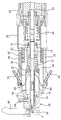
- FIG. 1 and 2 show an embodiment of an automatic driver provided with a screw automatic feeding mechanism according to the present invention.
- the reference numeral 10 denotes an automatic driver main body, and the tip end portion of the rotary output shaft 12 projecting from the side of a drive motor (not shown) provided inside the automatic driver main body 10
- a bit 14 as a tool is detachably mounted.
- a cylindrical suction guide 16 is provided so as to surround the entire bit 14, and a rear end portion of the suction guide 16 is provided in a cylindrical suction guide holder 20. It is accommodated so as to be movable in the longitudinal direction.
- an air passage 48 is provided in a part of the movable outer cylinder 32, and the air passage 48 is airtightly formed between the fixed inner cylinder 26 of the automatic driver main body 10 and the movable outer cylinder 32.
- a second vent pipe 52 communicating with the fluid chamber 50 and communicating with the vent path 48 is provided in a part of the movable outer cylinder 32 so as to supply air pressure from the outside. That is, the movable outer cylinder 32 and the fixed inner cylinder 26 constitute an air cylinder mechanism which moves the screw supply holding member 30 in the axial direction of the rotation output shaft 12.
Landscapes
- Engineering & Computer Science (AREA)
- Mechanical Engineering (AREA)
- Details Of Spanners, Wrenches, And Screw Drivers And Accessories (AREA)
Applications Claiming Priority (2)
| Application Number | Priority Date | Filing Date | Title |
|---|---|---|---|
| JP2012-116333 | 2012-05-22 | ||
| JP2012116333A JP5921332B2 (ja) | 2012-05-22 | 2012-05-22 | 自動ドライバーへのねじの自動供給および装着方法並びにねじ自動供給機構を備えた自動ドライバー |
Publications (1)
| Publication Number | Publication Date |
|---|---|
| WO2013175920A1 true WO2013175920A1 (fr) | 2013-11-28 |
Family
ID=49623619
Family Applications (1)
| Application Number | Title | Priority Date | Filing Date |
|---|---|---|---|
| PCT/JP2013/061855 Ceased WO2013175920A1 (fr) | 2012-05-22 | 2013-04-23 | Procédé pour fourniture et montage automatiques de vis sur un tournevis automatique, et tournevis automatique comportant un mécanisme de fourniture de vis automatique |
Country Status (2)
| Country | Link |
|---|---|
| JP (1) | JP5921332B2 (fr) |
| WO (1) | WO2013175920A1 (fr) |
Cited By (6)
| Publication number | Priority date | Publication date | Assignee | Title |
|---|---|---|---|---|
| CN104117848A (zh) * | 2014-07-25 | 2014-10-29 | 青岛乾程电子科技有限公司 | 一种连续式自动锁电表螺丝方法 |
| CN105537922A (zh) * | 2016-03-07 | 2016-05-04 | 河北航天振邦精密机械有限公司 | 一种双工位定子螺钉机及其安装方法 |
| CN105621069A (zh) * | 2014-11-21 | 2016-06-01 | 富士通株式会社 | 输送管、输送管器具、以及输送装置 |
| CN108393683A (zh) * | 2018-04-19 | 2018-08-14 | 广东万盛兴智能技术研究院有限公司 | 一种自动锁螺钉机构及自动锁螺钉方法 |
| CN114408586A (zh) * | 2022-02-10 | 2022-04-29 | 博众精工科技股份有限公司 | 一种输料管及物料输送装置 |
| CN114655711A (zh) * | 2022-05-05 | 2022-06-24 | 江苏威马悦达智能装备有限公司 | 一种小型零部件气动送料缓冲装置 |
Families Citing this family (8)
| Publication number | Priority date | Publication date | Assignee | Title |
|---|---|---|---|---|
| CN103737307B (zh) * | 2013-12-30 | 2016-02-17 | 东莞市冈田电子科技有限公司 | 一种转盘供料全自动锁附机 |
| CN104002128A (zh) * | 2014-05-22 | 2014-08-27 | 昆山市大久电子有限公司 | 节省人力的自动螺丝刀 |
| CN104002126A (zh) * | 2014-05-22 | 2014-08-27 | 昆山市大久电子有限公司 | 全自动螺丝刀 |
| JP6232585B2 (ja) * | 2014-06-23 | 2017-11-22 | パナソニックIpマネジメント株式会社 | 螺子供給装置 |
| JP6467619B2 (ja) * | 2014-06-23 | 2019-02-13 | パナソニックIpマネジメント株式会社 | 螺子取り付け装置 |
| CN104308516A (zh) * | 2014-09-24 | 2015-01-28 | 福建省新威电子工业有限公司 | 自动锁螺丝机 |
| KR101815484B1 (ko) * | 2015-04-08 | 2018-01-09 | 엄명용 | 나사공급용 카트리지 |
| CN105354999A (zh) * | 2015-11-25 | 2016-02-24 | 高佳 | 一种桌面型自动锁螺丝机异常警示器 |
Citations (6)
| Publication number | Priority date | Publication date | Assignee | Title |
|---|---|---|---|---|
| JPS6239924U (fr) * | 1985-08-27 | 1987-03-10 | ||
| JPS6274977U (fr) * | 1985-10-30 | 1987-05-13 | ||
| JPH0332579A (ja) * | 1989-06-29 | 1991-02-13 | Teac Corp | 自動ねじ締付機 |
| JPH04164715A (ja) * | 1990-10-27 | 1992-06-10 | Yoshitaka Aoyama | 部品供給装置 |
| JP3041001B2 (ja) * | 1989-08-25 | 2000-05-15 | 勝行 戸津 | 自動ねじ締め装置 |
| US20110130767A1 (en) * | 2009-12-01 | 2011-06-02 | Philip Watt | Screw delivery system |
-
2012
- 2012-05-22 JP JP2012116333A patent/JP5921332B2/ja active Active
-
2013
- 2013-04-23 WO PCT/JP2013/061855 patent/WO2013175920A1/fr not_active Ceased
Patent Citations (6)
| Publication number | Priority date | Publication date | Assignee | Title |
|---|---|---|---|---|
| JPS6239924U (fr) * | 1985-08-27 | 1987-03-10 | ||
| JPS6274977U (fr) * | 1985-10-30 | 1987-05-13 | ||
| JPH0332579A (ja) * | 1989-06-29 | 1991-02-13 | Teac Corp | 自動ねじ締付機 |
| JP3041001B2 (ja) * | 1989-08-25 | 2000-05-15 | 勝行 戸津 | 自動ねじ締め装置 |
| JPH04164715A (ja) * | 1990-10-27 | 1992-06-10 | Yoshitaka Aoyama | 部品供給装置 |
| US20110130767A1 (en) * | 2009-12-01 | 2011-06-02 | Philip Watt | Screw delivery system |
Cited By (7)
| Publication number | Priority date | Publication date | Assignee | Title |
|---|---|---|---|---|
| CN104117848A (zh) * | 2014-07-25 | 2014-10-29 | 青岛乾程电子科技有限公司 | 一种连续式自动锁电表螺丝方法 |
| CN105621069A (zh) * | 2014-11-21 | 2016-06-01 | 富士通株式会社 | 输送管、输送管器具、以及输送装置 |
| CN105537922A (zh) * | 2016-03-07 | 2016-05-04 | 河北航天振邦精密机械有限公司 | 一种双工位定子螺钉机及其安装方法 |
| CN108393683A (zh) * | 2018-04-19 | 2018-08-14 | 广东万盛兴智能技术研究院有限公司 | 一种自动锁螺钉机构及自动锁螺钉方法 |
| CN114408586A (zh) * | 2022-02-10 | 2022-04-29 | 博众精工科技股份有限公司 | 一种输料管及物料输送装置 |
| CN114408586B (zh) * | 2022-02-10 | 2024-01-09 | 博众精工科技股份有限公司 | 一种输料管及物料输送装置 |
| CN114655711A (zh) * | 2022-05-05 | 2022-06-24 | 江苏威马悦达智能装备有限公司 | 一种小型零部件气动送料缓冲装置 |
Also Published As
| Publication number | Publication date |
|---|---|
| JP2013240868A (ja) | 2013-12-05 |
| JP5921332B2 (ja) | 2016-05-24 |
Similar Documents
| Publication | Publication Date | Title |
|---|---|---|
| WO2013175920A1 (fr) | Procédé pour fourniture et montage automatiques de vis sur un tournevis automatique, et tournevis automatique comportant un mécanisme de fourniture de vis automatique | |
| JP4261117B2 (ja) | 打込工具 | |
| JP5103225B2 (ja) | チャック装置 | |
| JP3041001B2 (ja) | 自動ねじ締め装置 | |
| KR100926375B1 (ko) | 자동 체결기 | |
| JP6350853B2 (ja) | 自動ドライバーにおけるねじ自動供給装置 | |
| CN102205531B (zh) | 打入工具 | |
| JP2013240868A5 (fr) | ||
| CN116348248A (zh) | 用于自动化制造螺纹连接装置的设备 | |
| JP4577495B2 (ja) | ネジ、釘等の打込機における打込ガイド機構 | |
| JP4182031B2 (ja) | ナット供給装置 | |
| US1499887A (en) | Screw-driving machine | |
| CN102666044B (zh) | 具有深度调节机构的电动工具 | |
| JP7454226B2 (ja) | 自動ネジ締め装置 | |
| CN112388549A (zh) | 自动式开口扳手 | |
| CN214983261U (zh) | 3d打印机及其送料装置 | |
| JP7554702B2 (ja) | 自動部品締結機 | |
| JPH0630347Y2 (ja) | 螺合装置 | |
| JPH05500188A (ja) | エアフィードペックドリル装置 | |
| JP2000005948A (ja) | 自動ねじ締め機 | |
| JP6604068B2 (ja) | 打込み工具 | |
| JP6345056B2 (ja) | ブレード用治具 | |
| JPH11156648A (ja) | 自動ねじ締め機 | |
| JP2000052164A (ja) | 自動ねじ締め機 | |
| CN223947983U (zh) | 加工组件、加工装置和加工设备 |
Legal Events
| Date | Code | Title | Description |
|---|---|---|---|
| 121 | Ep: the epo has been informed by wipo that ep was designated in this application |
Ref document number: 13794747 Country of ref document: EP Kind code of ref document: A1 |
|
| NENP | Non-entry into the national phase |
Ref country code: DE |
|
| 122 | Ep: pct application non-entry in european phase |
Ref document number: 13794747 Country of ref document: EP Kind code of ref document: A1 |