WO2013178465A2 - Procédé de combustion totale et à bruit réduit d'un mélange combustible-air, et brûleur correspondant - Google Patents
Procédé de combustion totale et à bruit réduit d'un mélange combustible-air, et brûleur correspondant Download PDFInfo
- Publication number
- WO2013178465A2 WO2013178465A2 PCT/EP2013/060032 EP2013060032W WO2013178465A2 WO 2013178465 A2 WO2013178465 A2 WO 2013178465A2 EP 2013060032 W EP2013060032 W EP 2013060032W WO 2013178465 A2 WO2013178465 A2 WO 2013178465A2
- Authority
- WO
- WIPO (PCT)
- Prior art keywords
- tissue membrane
- flame
- holes
- flame arrester
- burner
- Prior art date
- Legal status (The legal status is an assumption and is not a legal conclusion. Google has not performed a legal analysis and makes no representation as to the accuracy of the status listed.)
- Ceased
Links
Images



Classifications
-
- F—MECHANICAL ENGINEERING; LIGHTING; HEATING; WEAPONS; BLASTING
- F23—COMBUSTION APPARATUS; COMBUSTION PROCESSES
- F23D—BURNERS
- F23D14/00—Burners for combustion of a gas, e.g. of a gas stored under pressure as a liquid
- F23D14/46—Details
- F23D14/48—Nozzles
- F23D14/58—Nozzles characterised by the shape or arrangement of the outlet or outlets from the nozzle, e.g. of annular configuration
-
- F—MECHANICAL ENGINEERING; LIGHTING; HEATING; WEAPONS; BLASTING
- F23—COMBUSTION APPARATUS; COMBUSTION PROCESSES
- F23D—BURNERS
- F23D14/00—Burners for combustion of a gas, e.g. of a gas stored under pressure as a liquid
- F23D14/46—Details
- F23D14/72—Safety devices, e.g. operative in case of failure of gas supply
- F23D14/82—Preventing flashback or blowback
-
- F—MECHANICAL ENGINEERING; LIGHTING; HEATING; WEAPONS; BLASTING
- F23—COMBUSTION APPARATUS; COMBUSTION PROCESSES
- F23D—BURNERS
- F23D2203/00—Gaseous fuel burners
- F23D2203/10—Flame diffusing means
- F23D2203/102—Flame diffusing means using perforated plates
-
- F—MECHANICAL ENGINEERING; LIGHTING; HEATING; WEAPONS; BLASTING
- F23—COMBUSTION APPARATUS; COMBUSTION PROCESSES
- F23D—BURNERS
- F23D2203/00—Gaseous fuel burners
- F23D2203/10—Flame diffusing means
- F23D2203/105—Porous plates
-
- F—MECHANICAL ENGINEERING; LIGHTING; HEATING; WEAPONS; BLASTING
- F23—COMBUSTION APPARATUS; COMBUSTION PROCESSES
- F23D—BURNERS
- F23D2203/00—Gaseous fuel burners
- F23D2203/10—Flame diffusing means
- F23D2203/106—Assemblies of different layers
-
- F—MECHANICAL ENGINEERING; LIGHTING; HEATING; WEAPONS; BLASTING
- F23—COMBUSTION APPARATUS; COMBUSTION PROCESSES
- F23D—BURNERS
- F23D2900/00—Special features of, or arrangements for burners using fluid fuels or solid fuels suspended in a carrier gas
- F23D2900/00003—Fuel or fuel-air mixtures flow distribution devices upstream of the outlet
Definitions
- the invention relates to a method for complete and noise-reduced combustion of a fuel-air mixture and a burner with a surface combustion.
- tissue membrane which consists of a sintered porous membrane fiber plate.
- This tissue membrane has a regular hole pattern on transverse holes occupying a passage opening of the membrane of 5 to 35% of the entire surface of the membrane.
- Such a membrane is arranged on an outlet side of a housing of the burner, wherein the funnel-shaped transverse stub holes are arranged with the funnel side on a burner side. Also upstream of the burner side, a mixture distribution plane is arranged at a distance from the tissue membrane, which has through holes.
- the fuel-air mixture fed into the housing via a supply line flows through the through-bores of the mixture distribution plane and flows out via the transverse holes of the tissue membrane to the exit side to form a flame field.
- the regular arrangement of the transverse holes in the tissue membrane to the advantage of uniform emergence of the fuel-air mixture over the entire tissue membrane is achieved with only a slight pressure drop, but the risk of the occurrence of resonances in the gas stream is given, resulting in unpleasant whistling. Therefore, it is proposed according to Figures 8 and 9, to introduce a wire mesh between the mixture distribution plane and the tissue membrane to reduce the occurrence of these whistling noises.
- the invention has for its object to provide a method for combustion of a fuel-air mixture and a burner, whereby a complete combustion at a high surface load and a noise reduction and a reduced emission is possible.
- the flashback barrier is positioned upstream of the tissue membrane at a distance to form a free passage space or flow space for the fuel-air mixture.
- the perforated grid of the tissue membrane and the perforated grid of the flame arrester are positioned relative to each other by rotating and / or displacing the flashback arrestor and / or the tissue membrane towards each other into an aligned position be converted into a twisted arrangement to each other.
- the skew is 0 ° or the displacement is zero.
- Such an arrangement further allows noise-reduced combustion due to the free passage space between the mixture distribution plane and the tissue membrane.
- the noise between the mixture distribution plane and the sound-damping layer is reduced by the sound-damping layer introduced in the prior art, whistling noise is again generated due to the diffuse inflow of the fuel-air mixture to the tissue membrane and the resulting flow through the tissue membrane.
- the aligned arrangement of the perforations of the tissue membrane and the flame arrester stable individual flames can be formed at the through-holes, which are assigned to the through-holes in alignment, whereby resonances are reduced.
- the tissue screen pitch pattern and flame arrestor grid pattern can be positioned by twisting the flame arrestor or tissue membrane, or both, in a twisted relationship to each other.
- the twisted assembly includes at least one aligned through hole of the flame arrester to a through hole of the fabric membrane, wherein the further through holes and through holes have a staggered position to each other.
- At least one so-called flame nest can be created, that is to say that the individual flames within a flame matrix of the flame nest are not all aligned parallel to one another and extend at right angles from the surface of the tissue membrane into a burner space, but at least one central flame Main flame is directed as a single flame vertically into the burner chamber and these are provided surrounding a plurality of individual flames, which incline at a deflection angle to the main flame of this.
- a larger inclination of the individual flames due to a larger disturbance of the flow path, which is achieved by an enlarged offset between the through hole and the through hole associated through hole. This can be a detuning to reduce the resonances occurring, whereby the noise reduction is achieved in the surface combustion.
- a shift can also take place.
- An advantageous embodiment of the method provides that, starting from an aligned arrangement of the hole pattern of the through holes of the tissue membrane for further noise reduction resonances occurring in the perforation grid of the tissue membrane and the Lochrast réelle the flame arrester are mutually at least slightly rotated.
- one or more flame nests can be formed as a function of the rotation or the angle of rotation.
- Such flame nests have a central main flame and, with increasing distance in the radial outward direction, attenuated and outwardly inclined main flames which form perturbation regions at the adjoining regions of the flame nests.
- further noise reduction and reduction of resonances in the tissue membrane can be achieved by detuning or influencing the resonance frequency of the flame matrix or the tissue membrane.
- This rotation can also take place starting from the twisted arrangement in an aligned arrangement.
- a longitudinal central axis of the tissue membrane is aligned congruently with a longitudinal central axis of the non-return barrier such that the perforated grid of the flame arrester and the grid of holes of the tissue membrane are aligned with each other and the rotation of the tissue membrane or the flame arrester or both about the longitudinal central axis.
- a controlled rotation for the targeted formation of at least one flame nest can be achieved.
- the number of flame nests is increased by an increasing rotation of the tissue membrane to the flame arrester to each other and reduced an area of the respective flame nest.
- the emerging in the tissue membrane outlet noise can be further reduced, the flame matrix is maintained approximately upright.
- the tissue membrane and the flame arrester are preferably adjusted to one another with a twist angle of less than 15 °, in particular less than 10 °. Such small rotations suffice to achieve a noise reduction.
- Another parameter for improving the noise reduction is achieved by the setting or the predetermination of the distance between the tissue membrane and the flame arrester, which are preferably arranged at a distance between 1 and 10 mm, in particular 5 to 7 mm.
- This distance is preferably variably adjustable and can be selected as a function of the supply of the fuel-air mixture and the selection of the fuel-air mixture and in dependence on the number and / or size of the through holes or through-bore in the tissue membrane and / or the flashback become.
- the object underlying the invention is further achieved by a burner with a surface combustion, wherein the perforated grid of the tissue membrane and the perforated grid of the flame arrester are aligned aligned with each other, wherein between the flame arrester and the tissue membrane, a free passage space is provided.
- a burner with a surface combustion wherein the perforated grid of the tissue membrane and the perforated grid of the flame arrester are aligned aligned with each other, wherein between the flame arrester and the tissue membrane, a free passage space is provided.
- free-jet of the fuel-air mixture can form, which reach the tissue membrane and exit via the through holes in the tissue membrane and form a single flame.
- the porosity of the tissue membrane forms a holding flame between the individual individual flames.
- Such a flame matrix formed from the holding flame with main flames or individual flames protruding from the holding flame has the advantage that cooling of the individual flame is achieved at the root or at the surface of the tissue membrane, which in turn results in a significantly higher surface load. This improves combustion and reduces CO and NO x emissions. At the same time can be done by the one flow space a calmed supply of the fuel-air mixture between the flame arrester and the fabric membrane, whereby a noise reduction is achieved.
- a twisted arrangement of the fabric membrane and / or the flame arrester may be provided within the plane of extension of the burner by a twist angle.
- a slight twist of the tissue membrane is understood to flame retardation or vice versa, so that at least the aligned arrangement of Lochrasterept is at least left slightly.
- a noise reduction can also be achieved by such a positioning, while maintaining the advantages of the significantly higher surface load described above.
- a preferred embodiment of the burner provides that the hole spacing of the through holes of the flame arrestor is half as large as the hole spacing of the through holes of the tissue membrane.
- the hole diameter of the through holes in the fabric membrane and the hole diameter of the through holes in the flame arrestor are preferably equal to or in a range of +/- 20% to each other. As a result, a particularly good passage behavior of the fuel-air mixture from the flame arrestor through the tissue membrane can be made possible for the formation of large individual flames. Particularly preferably, the hole diameters of the flame arrester are larger than those of the tissue membrane.
- the matrix of the through-hole in the flame arrester and / or the matrix of the through-holes of the fabric membrane are formed as two-dimensional Bravais grids.
- These two-dimensional Bravais lattices may be formed as skewed lattices as well as square, rectangular, hexagonal and centered rectangular lattices, the latter being the only one not primitive.
- a preferred embodiment of the burner provides that the through holes of the fabric membrane have a hole spacing of 2 to 10 mm and a hole diameter of the through hole of 1 to 3 mm and the through holes of the flame arrester have a hole spacing of 1.5 to 5 mm and a hole diameter of 0 , 8 to 3.6 mm. These perforations enable a particularly high surface load with a high noise reduction.
- the burner may have a twisting device between the fabric membrane and the flame arrester, or the fabric membrane and / or the flashback are received by a twisting device, whereby a twist angle of the perforated grid of the fabric membrane and the flame arrester is adjustable.
- the twisting device is designed such that the tissue membrane and the flame arrester are arranged congruent with respect to their longitudinal central axes and the tissue membrane and / or the flame arrester are rotatable about the respective longitudinal central axis. As a result, a targeted detuning of the resonance frequencies and the formation of flame nests can be achieved.
- Such twisting devices may preferably be provided in flat burners with a round, square, rectangular or polygonal tissue membrane and / or flame arrester.
- the tissue membrane or flashback barrier may be provided to provide a twisted arrangement of the tissue membrane or flashback barrier or both to each other by their edge trim outside of the grid of holes, thereby providing a twisted arrangement of the tissue membrane for flashback given is.
- edge trimming can also be done on site to take into account the other parameters of the burner design and / or the burner air mixture in the noise reduction.
- the tissue membrane and / or the flame arrester or both may be fastened to each other twisted in the housing of the burner. This represents, starting from an initially aligned arrangement of the hole patterns a simple setting.
- a further alternative embodiment of the burner provides that in a strip burner with a strip-shaped tissue membrane and a strip-shaped flame arrester by a one-dimensional displacement of the hole grid along the longitudinal axis of the housing strip burner noise reduction is adjustable. By such a shift, which may also be two-dimensional, a noise reduction to the twisted arrangement is made possible analogously.
- the aligned or twisted arrangement of the perforated grid of the tissue membrane and the flame arrester to each other can be provided both in flat burners, cylinder burners and ingot burners.
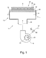
- FIG. 1 shows a schematic sectional view through a burner head with an associated burner fan of a burner
- FIG. 2 shows a schematic plan view of a tissue membrane of the burner according to FIG. 1,
- FIG. 3 is a diagrammatically enlarged side view of a fabric membrane and associated flame arrester.
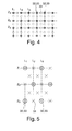
- FIG. 4 shows a schematic top view of FIG. 3 with a matrix of mutually arranged through-holes of the tissue membrane to through-holes of the flame arrestor barrier
- FIG. 5 shows a schematic top view of FIG. 3 of an alternative embodiment to FIG. 4, FIG.
- FIG. 6 shows a schematic view of a fabric membrane, at least with a flame arrestor block arranged twisted thereto,
- FIG. 7 shows a schematic side view of FIG. 6,
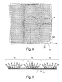
- FIG. 8 shows an alternative arrangement of the fabric membrane for the flashback arrestor according to FIG. 6,
- FIG. 9 shows a schematic side view of FIG. 8,
- Figure 10 is another view from above of a twisted arrangement of the tissue membrane for flame arrestor and
- Figures 11a and b are schematic views of a strip-shaped fabric membrane for flame arrestor.
- FIG. 1 schematically shows a burner 11 with a burner head 12.
- This comprises a housing 14, which receives a tissue membrane 16 on its outlet side.
- a flame arrester 17 is arranged in the housing 14 at a distance from the tissue membrane 16.
- an air supply line 23 the supply of air.
- the fuel-air mixture generated by the fan 19 is supplied via the supply line 18 to the burner head 12 so that it flows through the flame arrestor 17 and formed between the flame arrestor 17 and the tissue membrane 16 flow space 26 and after emerging from the tissue membrane 16 forms a flame matrix 27 on the burner side.
- This flame matrix 27 comprises individual flames 28 and holding flames 29 arranged between them, the individual flames 28 protruding from the holding flame 29.
- the flame matrix 27 points, for example, into a combustion chamber of a boiler.
- the burner can be operated on gas appliances in accordance with EN 676 "Gas fan burners", and operation in accordance with EN 746-2 on thermal processing plants is also possible in the industrial and commercial sectors.
- FIG. 2 shows a schematic view of the tissue membrane 16 of the burner head 12 according to FIG.
- This tissue membrane 16 has at the edge holes 31, which serve as mounting holes on the burner head 12 and housing 14.
- the tissue membrane 16 also has a plurality of through holes 32 which include a grid of holes and allow passage of the fuel-air mixture.
- the construction of such a membrane is evident from DE 10 2010 051 415.2, to which reference is made in its entirety and is the subject of this application.
- This burner tissue or this tissue membrane 16 make possible a combustion process which is described in DE 10 2010 051 414.4, to which reference is also made in its entirety and is the subject of this application.
- the tissue membrane 16 comprises a perforated grid in which the individual through-holes are spaced apart on a surface of, for example, 200 ⁇ 200 mm with, for example, a hole spacing of between 4 and 10 mm.
- the hole diameters of the through holes 32 are, for example, 0.5 to 3 mm.
- FIG. 3 shows a schematically enlarged view of the tissue membrane 16 and the flame arrester block 17 associated therewith in the burner head 12 according to FIG.
- FIG. 4 shows a plan view of FIG. 3.
- the flame arrester 17 comprises a perforated grid with through-holes 33, which preferably have half the distance between the through-holes of the fabric membrane 16, so that they comprise a distance of 1.5 to 5 mm.
- the same hole diameter of the through hole 39 is provided as with the through holes 32 or with a deviation in a range of +/- 20%.
- the perforations of the fabric membrane 16 and the flame arrester 17 are aligned with each other, that is, maximum coverage of the through holes 32 and through-holes 33 is provided.
- each second through-hole 33 along the lines L1, L2, L3, etc. and every other through-hole 33 along the lines Z1, Z2, Z3, etc. form a straight passage between the through-hole 33 and the through-hole 32.
- a rectangular-centered, two-dimensional Bravais grid is formed.
- the intermediate through hole 33 - ie every second through hole 33 - is covered by a surface portion of the fabric membrane 16.
- a free jet 35 for the holding flame 29 blowing on the tissue membrane 16 is formed.
- a continuous free jet 34 forming the individual flame 28 Adjacent to this, a continuous free jet 34 forming the individual flame 28 is formed.
- a flame matrix 27, as shown schematically in FIG. 3, is formed, wherein the single flame 28 is formed by the aligned through holes 33 and through holes 32 because of the continuous free jets 34 and the retaining flame 29 is supported by the concealed through holes 33 because of the blowing free jets 35 becomes.
- This is achieved in particular by the porosity of the tissue membrane 16 and causes a cooling of the flame root of the individual flame 28 and a cooling of the burner surface of the tissue membrane 16. This allows a high surface load.
- a noise reduction and reduction of CO and NO x emissions can be achieved by this ordered flame matrix 27.
- Another parameter for adjusting this flame matrix 27 may be the distance between the tissue membrane 16 and the flame arrestor 17.
- a distance in the above-described Lochrasttation from 2 to 10 mm, in particular 5 to 7 mm, given.
- the free flow space 26 is formed, that is, no further materials or the flow obstructing objects or objects are provided thereon, so that the flows formed by the through hole 33 of the flame arrester 17 undisturbed on the fabric material 16th can strike or pass through the aligned through holes 23 therethrough.
- the pitch pattern of the tissue membrane 16 and the pitch of the flame arrester 17 may be formed identically.
- the through holes 32 and through holes 33 are arranged in alignment with each other.
- FIG. 5 shows an alternative embodiment of a matrix of the through-holes 32 of the fabric membrane 16 and the through-holes 33 of the flame arrester 17.
- This matrix is designed as a two-dimensional hexagonal Bravais lattice.
- each second through-hole 32 of the fabric membrane 36 is congruent with the through-hole 32 of the flame arrester 17.
- the pitch of the lines Z1, Z2, Z3 is twice as large relative to the lines L1, L2, L3.
- FIG 6 an arrangement of the tissue membrane 16 and the flame arrester 17 is shown, if a further noise reduction is required.
- a rotation of the perforated grid of the tissue membrane 16 and the perforated grid of the flashback catch 17 from the aligned alignment or a twisted positioning takes place to each other.
- This twisted arrangement or positioning is to be understood in that the flame arrester 17 and the fabric membrane 16 initially maintained the same distance and also remain aligned in parallel.
- the rotation takes place about an axis aligned perpendicular to the plane of extent of the tissue membrane or the flame arrester, in particular the longitudinal central axis, or in that a displacement in the X and / or Y direction of the plane of extension of the tissue membrane 16 and / or the flame arrester 17 takes place.
- the tissue membrane 16 has been rotated about its longitudinal central axis 38, which is congruent with the longitudinal center axis 39 of the flame arrester block 17, for example by 1 °. Due to the rotation of the perforated rasters to each other, the hole pattern shown results in the plan view, wherein the upper membrane 16 is shown transparent to illustrate the effect.
- the through-holes 33 With the center near the longitudinal center axes 36, 37, there is provided an alignment of the through-holes 33 with the through-holes 32, but with further radially outward traveling, the offset between the through-holes 33 to the through-holes 32 becomes larger.
- Such an illustrated arrangement of the through holes 33 to the through holes 32 is referred to as a flame nest 40, wherein in the core at least one aligned through hole 33 and through hole 32 and outwardly offset from each other through holes 33 and through holes 32 are provided. This results in a flame matrix 27 according to FIG. 7.
- the free-jet effect is undisturbed as a fuel-air mixture, so that a free-jet vector 41 can emerge unhindered in the exit direction and corresponds to the resulting vector 43.
- an interfering vector 42 overlaps the free jet vector 41 so that a resulting vector 43 is formed and the individual flame 28 with respect to the longitudinal central axis 38 in the adjacent radially outwardly offset hole pair of the throughbore 33 to the through-hole 32 , 39 is inclined at an angle ⁇ 1 .
- the noise vector 42 becomes larger, so that the resulting vector 43 is aligned at a larger angle ⁇ 1 , ⁇ 2 , ⁇ 3 to the longitudinal central axis 38, 39 and at the same time the free jet vector 41 is reduced ,
- different exit frequencies are generated, which in turn enable a detuning, so that a further noise reduction at high Surface load is given.
- the same or similar frequencies and resulting interference are reduced in a plurality of through holes 32 with the same or very similar exit noise.
- FIG. 1 a plan view of the fabric membrane 16 and the flame arrester 17 it can be seen that at this angle of rotation of 4 ° seven flame nests 40 and in the corner regions have formed four half flame nests.
- FIG. 9 shows a side view to FIG. 8.
- a further disturbance in the adjacent areas of the flame nests 40 is achieved, which in turn leads to a further detuning and thus to a change in frequency of the exit noises lead to a resonance reduction.
- the tissue membrane 16 can be rotated relative to the non-return baffle 17 or the non-return baffle 17 relative to the tissue membrane 16 or both relative to one another.
- FIG. 11a shows a schematic view of a strip-shaped tissue membrane
- FIG. 11b shows a side view of the strip-shaped tissue membrane according to FIG. 11a and a corresponding flame arrestor barrier.
- tissue membrane 16 and flame arrester 17 are used for example in a inguinal burner, whose length comprises a multiple of the width.
- a single-row hole patterning of the through holes 32 and corresponding through holes 33 is provided.
- Figure 11b which corresponds for example to the line Z1 in Figure 4, so that reference is made.
- a two- or three-row perforation grid is provided in the case of tissue membranes 16 and flame arrester blocks 17, reference can be made to an arrangement according to lines Z1, Z2 and Z3 in FIG.
- a twisted arrangement analogous to Figures 6, 8 and 10 for this purpose, for example, the strip-shaped tissue membrane 16 is divided into short sections, so that the respective sections of the tissue membrane 16 in a twisted arrangement to the flame arrester 17 are positionable.
- Such an arrangement can also be provided in the case of a single-row perforated grid according to FIG. 11a.
- a reduction of the noise can also be effected by an at least slight offset of the perforation pattern of the tissue membrane 16 for perforating the flashback barrier 17 by a longitudinal displacement along the longitudinal axis of the strip-shaped strip burner or the longitudinal axis of the tissue membrane 16 and the flashback barrier 17.
Landscapes
- Engineering & Computer Science (AREA)
- Chemical & Material Sciences (AREA)
- Combustion & Propulsion (AREA)
- Mechanical Engineering (AREA)
- General Engineering & Computer Science (AREA)
- Gas Burners (AREA)
Priority Applications (1)
| Application Number | Priority Date | Filing Date | Title |
|---|---|---|---|
| EP13722468.9A EP2856027B1 (fr) | 2012-06-01 | 2013-05-15 | Procédé de combustion totale et à bruit réduit d'un mélange combustible-air, et brûleur correspondant |
Applications Claiming Priority (2)
| Application Number | Priority Date | Filing Date | Title |
|---|---|---|---|
| DE102012104741A DE102012104741A1 (de) | 2012-06-01 | 2012-06-01 | Verfahren zur vollständigen und geräuschreduzierten Verbrennung eines Brennstoff-Luft-Gemisches sowie Brenner hierzu |
| DE102012104741.3 | 2012-06-01 |
Publications (2)
| Publication Number | Publication Date |
|---|---|
| WO2013178465A2 true WO2013178465A2 (fr) | 2013-12-05 |
| WO2013178465A3 WO2013178465A3 (fr) | 2014-03-13 |
Family
ID=48430814
Family Applications (1)
| Application Number | Title | Priority Date | Filing Date |
|---|---|---|---|
| PCT/EP2013/060032 Ceased WO2013178465A2 (fr) | 2012-06-01 | 2013-05-15 | Procédé de combustion totale et à bruit réduit d'un mélange combustible-air, et brûleur correspondant |
Country Status (3)
| Country | Link |
|---|---|
| EP (1) | EP2856027B1 (fr) |
| DE (1) | DE102012104741A1 (fr) |
| WO (1) | WO2013178465A2 (fr) |
Cited By (2)
| Publication number | Priority date | Publication date | Assignee | Title |
|---|---|---|---|---|
| EP3184892A1 (fr) * | 2015-12-22 | 2017-06-28 | Bosch Termotecnologia S.A. | Brûleur |
| EP4141321A1 (fr) * | 2021-08-23 | 2023-03-01 | Viessmann Climate Solutions SE | Dispositif de brûleur à gaz avec dispositif arrête-flamme |
Families Citing this family (4)
| Publication number | Priority date | Publication date | Assignee | Title |
|---|---|---|---|---|
| DE202014101097U1 (de) * | 2014-03-11 | 2015-06-12 | Ulrich Dreizler | Brenner mit einer Oberflächenverbrennung |
| JP6853075B2 (ja) * | 2017-03-13 | 2021-03-31 | リンナイ株式会社 | 全一次燃焼式バーナ |
| JP2025502146A (ja) * | 2021-10-07 | 2025-01-24 | ポリドーロ ソチエタ ペル アツィオニ | プレミックスバーナー |
| DE102024202816A1 (de) * | 2024-03-25 | 2025-09-25 | Robert Bosch Gesellschaft mit beschränkter Haftung | Brennervorrichtung, Brennersystem und Heizgerät |
Citations (3)
| Publication number | Priority date | Publication date | Assignee | Title |
|---|---|---|---|---|
| EP0628146B1 (fr) | 1992-03-03 | 1998-12-16 | N.V. Bekaert S.A. | Plaque poreuse en fibres metalliques |
| DE102010051415A1 (de) | 2010-11-16 | 2012-05-16 | Ulrich Dreizler | Herstellverfahren einer Brennergewebemembrane |
| DE102010051414A1 (de) | 2010-11-16 | 2012-05-31 | Ulrich Dreizler | Verbrennungsverfahren |
Family Cites Families (13)
| Publication number | Priority date | Publication date | Assignee | Title |
|---|---|---|---|---|
| FR2063803A5 (fr) * | 1969-10-31 | 1971-07-09 | Gaz De France | |
| JPS6374925U (fr) * | 1986-11-05 | 1988-05-18 | ||
| SE468876B (sv) * | 1991-07-08 | 1993-04-05 | Staalhane Henrik | Anordning vid gaseldad grill |
| BE1007596A3 (nl) * | 1993-10-08 | 1995-08-16 | Bekaert Sa Nv | Poreuze metaalvezelplaat. |
| DE69503581T2 (de) * | 1994-08-26 | 1999-01-14 | Caradon Ideal Ltd., Hull, North Humberside | Gasbrenner |
| DE19724806A1 (de) * | 1996-06-11 | 1997-12-18 | Vaillant Joh Gmbh & Co | Vollvormischender atmosphärischer Strahlungsbrenner |
| JPH109522A (ja) * | 1996-06-25 | 1998-01-16 | Matsushita Electric Ind Co Ltd | 燃焼装置 |
| JPH109523A (ja) * | 1996-06-25 | 1998-01-16 | Matsushita Electric Ind Co Ltd | 燃焼装置 |
| DE19825047A1 (de) * | 1997-06-09 | 1998-12-10 | Vaillant Joh Gmbh & Co | Flächenbrenner |
| FR2835042B1 (fr) * | 2002-01-22 | 2004-12-17 | Mer Joseph Le | Bruleur a gaz, a face de combustion bipartite et chaudiere equipee d'un tel bruleur |
| ATE410105T1 (de) * | 2004-06-23 | 2008-10-15 | Willie H Best | Infrarot emittierende vorrichtung |
| BRPI0906568A2 (pt) * | 2008-01-28 | 2015-07-07 | Tetra Laval Holdings & Finance | Queimador de gás |
| KR101291627B1 (ko) * | 2011-10-14 | 2013-08-01 | 주식회사 경동나비엔 | 예혼합가스버너의 염공부 구조 |
-
2012
- 2012-06-01 DE DE102012104741A patent/DE102012104741A1/de not_active Withdrawn
-
2013
- 2013-05-15 EP EP13722468.9A patent/EP2856027B1/fr active Active
- 2013-05-15 WO PCT/EP2013/060032 patent/WO2013178465A2/fr not_active Ceased
Patent Citations (3)
| Publication number | Priority date | Publication date | Assignee | Title |
|---|---|---|---|---|
| EP0628146B1 (fr) | 1992-03-03 | 1998-12-16 | N.V. Bekaert S.A. | Plaque poreuse en fibres metalliques |
| DE102010051415A1 (de) | 2010-11-16 | 2012-05-16 | Ulrich Dreizler | Herstellverfahren einer Brennergewebemembrane |
| DE102010051414A1 (de) | 2010-11-16 | 2012-05-31 | Ulrich Dreizler | Verbrennungsverfahren |
Cited By (2)
| Publication number | Priority date | Publication date | Assignee | Title |
|---|---|---|---|---|
| EP3184892A1 (fr) * | 2015-12-22 | 2017-06-28 | Bosch Termotecnologia S.A. | Brûleur |
| EP4141321A1 (fr) * | 2021-08-23 | 2023-03-01 | Viessmann Climate Solutions SE | Dispositif de brûleur à gaz avec dispositif arrête-flamme |
Also Published As
| Publication number | Publication date |
|---|---|
| EP2856027B1 (fr) | 2016-07-13 |
| WO2013178465A3 (fr) | 2014-03-13 |
| DE102012104741A1 (de) | 2013-12-05 |
| EP2856027A2 (fr) | 2015-04-08 |
Similar Documents
| Publication | Publication Date | Title |
|---|---|---|
| EP2856027B1 (fr) | Procédé de combustion totale et à bruit réduit d'un mélange combustible-air, et brûleur correspondant | |
| DE69218531T2 (de) | Brenner mit geringer Erzeugung von Stickoxiden und kleine Verbrennungsvorrichtung | |
| DE102010051414B4 (de) | Verbrennungsverfahren mit kühler Flammenwurzel | |
| EP3289131B1 (fr) | Installation et procédé de consolidation et de structuration de fibres à un non-tissé | |
| DE102008020287B3 (de) | Abstandsgewirke mit geraden Kanälen in sich kreuzender Anordnung zwischen den Gewirkelagen | |
| EP3452650B1 (fr) | Structure ajourée synthétique avec chaînettes doubles | |
| DE69910106T2 (de) | Brennkammer | |
| DE2644996A1 (de) | Fadenkuehlvorrichtung | |
| DE60123437T2 (de) | Verfahren und vorrichtung zur verbesserung der isotropie von vliesstoffen | |
| EP2641023A2 (fr) | Procédé de déplacement pour la fabrication d'une membrane en tissu pour brûleur, permettant d'obtenir une base de flammes froide | |
| WO2006136231A1 (fr) | Systeme de fibres creuses | |
| EP3630304A1 (fr) | Filtre anti-flamme | |
| EP2864706B1 (fr) | Amélioration locale du mélange d'air et de combustible dans des brûleurs pourvus de générateurs de tourbillon comprenant des extrémités à aube entrecroisées dans la zone extérieure | |
| EP2382033B1 (fr) | Station de dérivation avec un dispositif mélangeur pour mélanger de l'eau et de la vapeur d'eau | |
| EP3159446B1 (fr) | Dispositif de traitement thermique d'une nappe de tissu textile | |
| DE69834669T2 (de) | Verbrennungsgerät | |
| EP4215661B1 (fr) | Procédé de fabrication de filets en métal précieux sur des tricoteuses rectilignes | |
| DE69410030T2 (de) | Flammenhalterplatte für Gasbrenner, Verfahren zu seiner Herstellung und Brenner mit einer solchen Platte | |
| CH703599B1 (de) | Brennkammer und Verfahren zum Betrieb einer Brennkammer. | |
| DE202021104211U1 (de) | Strahlregler | |
| DE102021120460A1 (de) | Strahlregler | |
| EP4215662A1 (fr) | Procédé de fabrication de filets en métal noble sur des tricoteuses rectilignes | |
| WO2008014842A1 (fr) | Dispositif pour la fabrication de non-tissés ajourés | |
| EP3979235B1 (fr) | Buse d'entrée d'air pour appareils de chauffage au gaz | |
| EP1939341A1 (fr) | Rouleau de gaufrage destiné à la fabrication d'une étoffe |
Legal Events
| Date | Code | Title | Description |
|---|---|---|---|
| DPE1 | Request for preliminary examination filed after expiration of 19th month from priority date (pct application filed from 20040101) | ||
| REEP | Request for entry into the european phase |
Ref document number: 2013722468 Country of ref document: EP |
|
| WWE | Wipo information: entry into national phase |
Ref document number: 2013722468 Country of ref document: EP |
|
| 121 | Ep: the epo has been informed by wipo that ep was designated in this application |
Ref document number: 13722468 Country of ref document: EP Kind code of ref document: A2 |