WO2013179877A1 - Dispositif d'évaluation de rupture de composant, procédé d'évaluation de rupture de composant, et programme informatique - Google Patents
Dispositif d'évaluation de rupture de composant, procédé d'évaluation de rupture de composant, et programme informatique Download PDFInfo
- Publication number
- WO2013179877A1 WO2013179877A1 PCT/JP2013/063286 JP2013063286W WO2013179877A1 WO 2013179877 A1 WO2013179877 A1 WO 2013179877A1 JP 2013063286 W JP2013063286 W JP 2013063286W WO 2013179877 A1 WO2013179877 A1 WO 2013179877A1
- Authority
- WO
- WIPO (PCT)
- Prior art keywords
- inclusion
- fatigue strength
- virtual
- stress
- deriving
- Prior art date
- Legal status (The legal status is an assumption and is not a legal conclusion. Google has not performed a legal analysis and makes no representation as to the accuracy of the status listed.)
- Ceased
Links
Images





Classifications
-
- G—PHYSICS
- G01—MEASURING; TESTING
- G01M—TESTING STATIC OR DYNAMIC BALANCE OF MACHINES OR STRUCTURES; TESTING OF STRUCTURES OR APPARATUS, NOT OTHERWISE PROVIDED FOR
- G01M13/00—Testing of machine parts
-
- G—PHYSICS
- G01—MEASURING; TESTING
- G01N—INVESTIGATING OR ANALYSING MATERIALS BY DETERMINING THEIR CHEMICAL OR PHYSICAL PROPERTIES
- G01N3/00—Investigating strength properties of solid materials by application of mechanical stress
- G01N3/32—Investigating strength properties of solid materials by application of mechanical stress by applying repeated or pulsating forces
-
- G—PHYSICS
- G06—COMPUTING OR CALCULATING; COUNTING
- G06F—ELECTRIC DIGITAL DATA PROCESSING
- G06F30/00—Computer-aided design [CAD]
- G06F30/20—Design optimisation, verification or simulation
-
- G—PHYSICS
- G06—COMPUTING OR CALCULATING; COUNTING
- G06F—ELECTRIC DIGITAL DATA PROCESSING
- G06F30/00—Computer-aided design [CAD]
- G06F30/20—Design optimisation, verification or simulation
- G06F30/23—Design optimisation, verification or simulation using finite element methods [FEM] or finite difference methods [FDM]
-
- G—PHYSICS
- G01—MEASURING; TESTING
- G01N—INVESTIGATING OR ANALYSING MATERIALS BY DETERMINING THEIR CHEMICAL OR PHYSICAL PROPERTIES
- G01N2203/00—Investigating strength properties of solid materials by application of mechanical stress
- G01N2203/02—Details not specific for a particular testing method
- G01N2203/0202—Control of the test
- G01N2203/0212—Theories, calculations
- G01N2203/0218—Calculations based on experimental data
-
- G—PHYSICS
- G06—COMPUTING OR CALCULATING; COUNTING
- G06F—ELECTRIC DIGITAL DATA PROCESSING
- G06F2119/00—Details relating to the type or aim of the analysis or the optimisation
- G06F2119/04—Ageing analysis or optimisation against ageing
-
- G—PHYSICS
- G06—COMPUTING OR CALCULATING; COUNTING
- G06F—ELECTRIC DIGITAL DATA PROCESSING
- G06F2119/00—Details relating to the type or aim of the analysis or the optimisation
- G06F2119/14—Force analysis or force optimisation, e.g. static or dynamic forces
Definitions
- the present invention relates to a component destructive evaluation device, a component destructive evaluation method, and a computer program, and is particularly suitable for use in evaluating the internal destructive performance of mechanical components.
- the fatigue fracture phenomenon is obtained under uniform stress by formulating the fatigue strength of mechanical parts and formulating the maximum inclusion size and maximum inclusion distribution by extreme value statistical processing. It is possible to perform fatigue design of machine parts in consideration of the volume effect that affects them. However, in the technique described in Non-Patent Document 1, the fatigue design of a machine part is performed in consideration of both the volume effect (inclusion size and density distribution) and the stress distribution inside the machine part. I can't. Moreover, in order to obtain
- the present invention has been made in view of the above problems, and an object of the present invention is to make it possible to evaluate the fracture performance of a machine part in consideration of the distribution of inclusions existing inside the machine part. .
- the component destruction evaluation method of the present invention is a component destruction evaluation method for evaluating the destruction performance of a machine component, and includes an inclusion contained in the sample from a sample made of the same type of material as that constituting the machine component.
- the inclusion size exceeds the threshold among the inclusions included in the sample based on the inclusion extraction step of extracting the inclusion and the inclusion size which is the size of the inclusion extracted by the inclusion extraction step
- the threshold excess inclusion number deriving step for deriving the number of inclusions exceeding the threshold that is the number of inclusions
- the distribution function of the inclusion size extracted by the inclusion extraction step follows a general Pareto distribution
- the inclusion size is
- the component destructive evaluation apparatus of the present invention is a component destructive evaluation apparatus for evaluating the destructive performance of a mechanical component, and is a size of an inclusion extracted from a sample made of the same kind of material as that constituting the mechanical component. Based on a certain inclusion size, out of the inclusions included in the sample, the threshold excess inclusion number deriving means for deriving the number of inclusions exceeding the threshold, which is the number of inclusions whose inclusion size exceeds the threshold, and the extraction Assuming that the distribution function of the inclusion size of the included inclusions follows a general Pareto distribution, the general Pareto is based on the extracted inclusion size, the number of inclusions exceeding the threshold, and the threshold.
- Coefficient deriving means for deriving a coefficient of distribution, out of inclusions included in the sample, the number of inclusions exceeding the threshold that is the number of inclusions whose inclusion size exceeds the threshold, and the inside of the sample
- a virtual inclusion ratio deriving means for deriving a virtual inclusion ratio that is a ratio with the number of inclusions exceeding zero that is the number of inclusions whose inclusion size exceeds 0 (zero) among the inclusions included; Based on the number of inclusions exceeding the threshold, the virtual inclusion ratio, and the volume of the sample, the virtual part in the case where the mechanical parts are equally divided by a plurality of virtual cells each including one inclusion.
- Virtual unit volume deriving means for deriving a virtual unit volume that is a volume of a cell, and evaluating the fracture performance of the mechanical part in units of virtual cells having the virtual unit volume derived by the virtual unit volume deriving means An index to be derived is derived, and the fracture performance of the machine part is evaluated using the derived index.
- the computer program of the present invention is a computer program for causing a computer to evaluate the fracture performance of a machine part, and includes inclusions extracted from a sample made of the same kind of material as that constituting the machine part.
- a threshold excess inclusion number derivation step for deriving a threshold excess inclusion number that is the number of inclusions whose inclusion size exceeds a threshold value among inclusions included in the sample based on the inclusion size that is a dimension; and Assuming that the distribution function of the extracted inclusion inclusion size follows a general Pareto distribution, based on the extracted inclusion inclusion size, the threshold excess inclusion number, and the threshold value,
- a coefficient deriving step for deriving a coefficient of a general Pareto distribution, and the number of inclusions whose inclusion size exceeds a threshold among the inclusions included in the sample A hypothetical inclusion which is a ratio of a certain number of inclusions exceeding a threshold and the number of inclusions exceeding zero, which is the number of inclusions whose inclusion size exceeds 0 (zero) among the inclusions included in
- a plurality of virtual cells each including one inclusion based on a virtual inclusion ratio deriving step for deriving a ratio, the number of inclusions exceeding the threshold, the virtual inclusion ratio, and the volume of the sample A virtual unit volume deriving step for deriving a virtual unit volume, which is a volume of the virtual cell when the machine part is equally divided in step 1, and causing the computer to execute the virtual unit volume derived by the virtual unit volume deriving step
- An index for evaluating the fracture performance of the machine part is derived in units of virtual cells having the following, and the fracture performance of the machine part is evaluated using the derived index.
- the machine parts are equally divided by a plurality of virtual cells each including one inclusion. Then, an index for evaluating the fracture performance of the machine part is derived for each virtual cell, and the fracture performance of the machine part is evaluated using the derived index. Therefore, the destruction performance of the machine part can be evaluated in consideration of the distribution of inclusions existing inside the machine part.
- FIG. 1 is a diagram illustrating an example of a hardware configuration of a component fatigue fracture evaluation apparatus.
- FIG. 2 is a diagram illustrating an example of a functional configuration of a component fatigue fracture evaluation apparatus.
- FIG. 3 is a diagram conceptually showing the virtual unit volume of the virtual cell.
- FIG. 4 is a diagram conceptually illustrating an example of a density function of inclusion dimensions.
- FIG. 5 is a diagram conceptually illustrating an example of a virtual cell.
- FIG. 6 is a diagram conceptually showing an overview of mechanical parts partitioned by virtual cells.
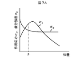
- FIG. 7A is a diagram conceptually illustrating an example of the relationship between the stress amplitude of the acting stress and the stress amplitude of the fatigue strength and the position of the mechanical component when the inclusion size is relatively large.
- FIG. 7A is a diagram conceptually illustrating an example of the relationship between the stress amplitude of the acting stress and the stress amplitude of the fatigue strength and the position of the mechanical component when the inclusion size is relatively large.
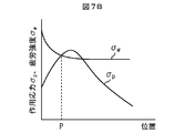
- FIG. 7B is a diagram conceptually illustrating an example of the relationship between the stress amplitude of the acting stress and the stress amplitude of the fatigue strength and the position of the mechanical component when the inclusion size ⁇ area is relatively medium.
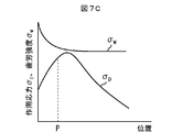
- FIG. 7C is a diagram conceptually illustrating an example of the relationship between the stress amplitude of the acting stress and the stress amplitude of the fatigue strength and the position of the mechanical component when the inclusion size ⁇ area is relatively small.
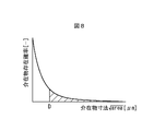
- FIG. 8 is a diagram conceptually illustrating an example of the relationship between the inclusion existence probability and the inclusion size in the virtual cell.
- FIG. 9 is a flowchart for explaining an example of the operation flow of the component fatigue fracture evaluation apparatus.
- FIG. 9 is a flowchart for explaining an example of the operation flow of the component fatigue fracture evaluation apparatus.
- FIG. 10 is a diagram showing the relationship between the distance (depth) from the surface of the wire of the coil spring and the stress amplitude of the residual stress of the coil spring.
- FIG. 11 is a diagram conceptually showing (part) of the virtual cells set for the coil spring.
- FIG. 12 is a diagram showing the fatigue strength excess probability of the coil springs of materials A and B and the experimental results (500 million fatigue failure probabilities) of each coil spring.
- FIG. 13 is a diagram showing the relationship between the distance (depth) from the surface of the round bar test piece and the stress amplitude of the residual stress of the round bar test piece.
- an inclusion having a dimension equal to or larger than a threshold is obtained by a method such as a slime extraction method in which a certain volume of material is dissolved in an electrolytic solution to extract only inclusions or an acid dissolution method You can measure how much exists.
- the minimum critical dimension of inclusions that can be collected is determined by the roughness of the filter of the apparatus, and not all inclusions can be extracted. Fortunately, internal fatigue failure is not a problem with small inclusions. Therefore, it is effective to evaluate the fatigue of machine parts using only the distribution of large inclusions that contribute to internal fatigue.
- the strength, internal stress, and the like may vary greatly depending on the location, and it is necessary to evaluate fatigue fracture in consideration of these.
- the present inventors quantitatively calculate the probability of exceeding the fatigue strength of a mechanical component when a stress state (average stress or repeated stress) is given as follows. I found a method. By using this method, it is possible to obtain a policy for determining an effective measure for preventing fatigue fracture.
- FIG. 1 is a diagram illustrating an example of a hardware configuration of a component fatigue fracture evaluation apparatus 100.
- the component fatigue fracture evaluation apparatus 100 is for evaluating the fracture performance of mechanical components.
- a component fatigue fracture evaluation apparatus 100 includes a CPU (Central Processing Unit) 101 and a ROM (Read Only). Memory) 102, RAM (Random Access Memory) 103, PD (Pointing Device) 104, HD (Hard Disk) 105, display device 106, speaker 107, communication I / F (Interface) 108, system And a bus 109.
- CPU Central Processing Unit
- ROM Read Only Memory
- RAM Random Access Memory
- PD Pointing Device
- HD Hard Disk
- display device 106 display device
- speaker 107 speaker
- communication I / F (Interface) 108 system And a bus 109.
- the CPU 101 controls the operation of the component fatigue fracture evaluation apparatus 100 in an integrated manner, and controls each component (102 to 108) of the component fatigue fracture evaluation apparatus 100 via the system bus 109.
- the ROM 102 stores a basic input / output system (BIOS) and an operating system program (OS), which are control programs for the CPU 101, programs necessary for the CPU 101 to execute processing described later, and the like.
- BIOS basic input / output system
- OS operating system program
- the RAM 103 functions as a main memory, work area, and the like for the CPU 101.
- the CPU 101 loads various computer programs and the like from the ROM 102 and necessary information from the HD 105 into the RAM 103, and executes various processes by executing the computer programs and the information.
- the PD 104 includes, for example, a mouse, a keyboard, and the like, and constitutes an operation input unit for an operator to input an operation to the component fatigue fracture evaluation apparatus 100 as necessary.
- the HD 105 constitutes storage means for storing various information, data, files, and the like.
- the display device 106 constitutes display means for displaying various information and images based on the control of the CPU 101.
- the speaker 107 constitutes an audio output unit that outputs audio related to various types of information based on the control of the CPU 101.
- the communication I / F 108 communicates various information and the like with an external device via a network based on the control of the CPU 101.
- a system bus 109 is a bus for connecting the CPU 101, ROM 102, RAM 103, PD 104, HD 105, display device 106, speaker 107, and communication I / F 108 so that they can communicate with each other.
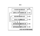
- FIG. 2 is a diagram illustrating an example of a functional configuration of the component fatigue fracture evaluation apparatus 100.
- the component fatigue fracture evaluation apparatus 100 assumes the number of inclusions existing in one machine part such as a spring based on the investigation result of the distribution of inclusions of the material constituting the machine part, Determine the probability that the fatigue strength will be exceeded for the stress state (average stress or repeated stress) where each inclusion is placed, and combine the results to determine the probability of excess fatigue strength for the entire machine part. calculate.
- the number of inclusions existing in one machine part such as a spring based on the investigation result of the distribution of inclusions of the material constituting the machine part.
- the component fatigue fracture evaluation apparatus 100 includes an inclusion distribution quantification unit 201, a virtual cell unit volume deriving unit 202, an estimated fatigue strength deriving unit 203, an acting stress amplitude deriving unit 204, and an excess fatigue strength.
- a probability deriving unit 205 and a fatigue strength excess probability output unit 206 are provided.
- ⁇ Inclusion Distribution Quantification Unit 201 First, measure the size of each inclusion (inclusion size ⁇ area [ ⁇ m]) contained in a sample made of the same type of material as the material constituting the machine part that is the subject of investigation of the fatigue strength excess probability (of the sample) Let the volume be V s [mm 3 ]).
- the inclusion dimension ⁇ area is a so-called “root area”, and is the square root ( ⁇ ) of the projected area (cross-sectional area of the inclusion) when the shape of the inclusion is projected onto a plane. Value.
- root area is a so-called “root area”, and is the square root ( ⁇ ) of the projected area (cross-sectional area of the inclusion) when the shape of the inclusion is projected onto a plane. Value.
- the shape of the inclusion is approximated to a simple figure (shape) such as a rectangle or ellipse, and the projected area of the inclusion (cross-sectional area of the inclusion) is estimated from the representative dimensions of the figure.
- the square root of the area may be the inclusion size ⁇ area.
- a value obtained by simply taking the square root of the product of the major axis and the minor axis, or the square root of the product of the major axis, the minor axis, and ⁇ is taken.
- the value may be an estimated value (inclusion size ⁇ area) of the projected area of the inclusion (cross-sectional area of the inclusion).
- ⁇ X represents X 1/2 (X to the power of 1/2)
- ⁇ area max represents area max 1/2 .
- Such inclusions can be extracted using, for example, a slime method.
- a sample is electrolyzed in a ferrous iron solution, the electrolyzed slime is collected in a mesh-like sampling bag, and residues other than inclusions made of non-ferrous metal are removed by a water tank operation. The residue remaining in the sampling bag is transferred to a magnetic dish and the residue is further removed, followed by sieving and separation.
- the slime method is a known technique as described in Patent Document 2 and the like, detailed description thereof is omitted here.
- the inclusion extraction process is not limited to the slime method.
- the inclusions contained in the sample may be extracted by using other methods such as acid dissolution method and microscopy, and the size of each inclusion ⁇ area may be measured.
- the inclusion distribution quantification unit 201 obtains information on the size of inclusions (inclusion size ⁇ area) extracted by the slime method among inclusions included in the sample, and the operation of the operator and the external device. The data is input and stored based on the communication. In the following description, the information on the inclusion size ⁇ area thus obtained is referred to as “actual measurement data” as necessary.
- the probability distribution of the inclusion size ⁇ area is represented by the conditional probability P of the inclusion whose inclusion size ⁇ area exceeds x.
- the density function p of the inclusion size ⁇ area is approximately expressed by the following formula (1) or (2).
- the distribution function is called differently depending on the value of the coefficient ⁇ , but these are collectively referred to as a density function of a general Pareto distribution.
- ⁇ area follows the general Pareto distribution.
- the inclusion distribution quantification unit 201 derives from the actually measured data the threshold excess inclusion number N u that is the number of inclusions whose inclusion size ⁇ area exceeds the threshold u.
- the inclusion distribution quantifying unit 201 is, for example, an average excess plot obtained by plotting the value of the following equation (3) or a median excess plot obtained by plotting the value of the following equation (4): Based on the threshold value u, the threshold value excess inclusion number N u can be obtained.
- the inclusion distribution quantification unit 201 displays the average excess plot or the median excess plot on the display device 106, determines the threshold u based on the operation of the PD 104 of the operator with respect to this display result, and exceeds the threshold u can be derived intervening the number as a threshold exceeded inclusions number N u.
- i is a variable [ ⁇ ] that specifies an inclusion
- x max is the maximum value [ ⁇ m] of the inclusion dimension ⁇ area included in the measured data.
- the threshold value u of the inclusion dimension ⁇ area does not need to be strictly determined, and the threshold value u of the inclusion dimension ⁇ area can be set to a size that is assumed to contribute to destruction.
- the average excess plot or the median excess plot is displayed on the display device 106, and the threshold value u is input by the operator so that the inclusion distribution quantification unit 201 derives the threshold excess inclusion number N u. I made it. However, this is not always necessary.
- an average excess plot or a median excess plot may be displayed on the display device 106, and the operator may be allowed to input the threshold excess inclusion number Nu .
- the operator himself performs the processing until obtaining the threshold excess inclusion number Nu (without involving the inclusion distribution quantification unit 201), and the inclusion distribution quantification unit 201 includes the threshold u and the threshold excess inclusion.
- the number of objects Nu may be input.
- the threshold u is set after all the inclusion dimensions ⁇ area extracted from each sample are combined. In this case, the threshold for each sample when a u s, it is obvious that a value of the threshold u exceeds the threshold u s.
- the inclusion distribution quantification unit 201 derives the coefficients ⁇ and ⁇ of the general Pareto distribution from the actually measured data.
- the coefficients ⁇ and ⁇ of the general Pareto distribution are derived using the maximum likelihood method.
- the distribution function H (y) of the general Pareto distribution is as shown in the following equation (5).
- the likelihood function L ( ⁇ , ⁇ ) is represented by the product of the density function h (y) represented by the following equation (6), and when the number of samples is n, the following equation (7) is obtained.
- the number of samples n, given threshold exceeded inclusions number N u
- the variable y, (x-u) is given (x is the inclusion size ⁇ area, u is the threshold value).
- the likelihood function L ( ⁇ , ⁇ ) is treated as a log likelihood l ( ⁇ , ⁇ ) expressed by the following equation (8), and the log likelihood l ( ⁇ , ⁇ ) are derived to maximize the coefficients ⁇ , ⁇ .
- the inclusion distribution quantification unit 201 derives the distribution function of the inclusion size ⁇ area and the coefficients ⁇ and ⁇ of the density function as described above.
- the inclusion distribution quantification unit 201 can be realized by using, for example, the CPU 101, the ROM 102, the RAM 103, the PD 104, the HD 105, the display device 106, and the communication I / F 108.
- FIG. 3 is a diagram conceptually showing the virtual unit volume V 0 of the virtual cell. As shown in FIG. 3, the sample volume V s is obtained by multiplying the virtual unit volume V 0 of the virtual cell by the number N 0 of inclusions contained in the sample. The volume V s of the sample is input by an operator's operation.
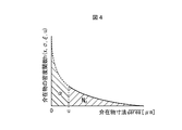
- FIG. 4 is a diagram conceptually illustrating an example of the density function h (x, ⁇ , ⁇ , u) of the inclusion size ⁇ area.
- the density function h (x, ⁇ , ⁇ , u) of the inclusion size ⁇ area determined from the coefficients ⁇ , ⁇ derived by the inclusion distribution quantifying unit 201, the integration range where the inclusion size ⁇ area is from the threshold u to ⁇ The value integrated with is 1.
- the virtual inclusion ratio ⁇ is in the sample volume V s with respect to the number N u of inclusions whose inclusion size ⁇ area exceeds the threshold u (the number Nu of excess inclusions exceeding the threshold). of inclusion sizes ⁇ area are representative of a ratio of 0 interposing the number exceeds (zero) N 0 (zero excess inclusions number N 0).
- the virtual unit volume V 0 of the virtual cell is expressed as the following equation (10).
- ⁇ is the number of inclusions in the range where the inclusion size ⁇ area is from 0 (zero) to the threshold u.
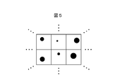
- FIG. 5 is a diagram conceptually illustrating an example of a virtual cell
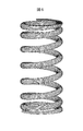
- FIG. 6 is a diagram conceptually illustrating an overview of mechanical parts (springs) partitioned by the virtual cell.
- One rectangular region shown in FIG. 5 is a virtual cell having a virtual unit volume V 0 , and the region of the machine part that is the object of investigation of the fatigue strength excess probability is represented by N Partition with V0 (identical) virtual cells.
- Each virtual cell contains one inclusion whose inclusion dimension ⁇ area exceeds 0 (zero), and the inclusion dimension ⁇ area is distributed according to the density function of the inclusion dimension ⁇ area. To do.
- Virtual cell unit volume deriving portion 202 derives a virtual unit volume V 0 which virtual cells, the N V0 amino virtual cells having a virtual unit volume V 0, the survey fatigue strength excess probability Set for machine parts.
- the number N V0 of virtual cells is expressed by the following equation (11).
- N V0 (V / V s ) ⁇ N u ⁇ ⁇ (11)
- V is the volume [mm 3 ] of the machine part that is the object of investigation of the fatigue strength excess probability, and is input by the operator.
- the virtual cell unit volume deriving unit 202 can be realized by using the CPU 101, the ROM 102, the RAM 103, and the PD 104, for example.
- mm 2 is expressed as a function of inclusion size ⁇ area, Vickers hardness Hv, and stress ratio R [ ⁇ ].
- the stress amplitude ⁇ w of the fatigue strength is expressed as in the following equation (12).
- ⁇ w ⁇ 1.56 ⁇ (Hv + 120) / ( ⁇ area max ) 1/6 ⁇ ⁇ ⁇ (1-R) / 2 ⁇ ⁇ (12)
- the equation (12) is originally an equation for estimating the fatigue limit, but the equation (12) is used as an equation for fatigue strength at about 10 7 times in consideration of the capability of the testing machine at the time of research.
- Hv Vickers hardness.
- R is a stress ratio and is expressed by the following equation (13).
- ⁇ is an influence multiplier of hardness and is expressed by the following equation (14).
- R ( ⁇ m ⁇ w ) / ( ⁇ m + ⁇ w ) (13)
- ⁇ 0.226 + Hv / 10000 (14)
- ⁇ m is the stress amplitude [N / mm 2 ] of the average stress of the machine part.
- the value of the Vickers hardness Hv is obtained from the result of the test of the material constituting the part. Further, the values of the average stress ⁇ m and the stress ratio R of the part are obtained from the load applied to the part and the dimension of the part.
- the stress ratio R the stress ratio of the equivalent stress at each position inside the component or the stress ratio of the main stress in the direction in which the fluctuation of the main stress at each position inside the component is maximized is adopted. To do. Which of these is adopted can be appropriately determined according to the components and the like.
- the inclusion size ⁇ area is determined by the distribution function of the inclusion size ⁇ area determined by the coefficients ⁇ and ⁇ derived by the inclusion distribution quantification unit 201 (see formula (1) or (2)). It is.
- the estimated fatigue strength deriving unit 203 inputs these values based on the operation by the operator, etc., calculates the equation (12), and applies a predetermined number of repeated loads to the machine part.
- the stress amplitude ⁇ w of the fatigue strength in each virtual cell set for the machine part is derived with respect to the stress ratio R in the virtual cell.
- a plurality of such stress amplitudes ⁇ w of fatigue strength are derived by differentiating the inclusion size ⁇ area max and the stress ratio R whose value varies depending on the virtual cell and the stress condition used. .
- the stress amplitude ⁇ w of the fatigue strength can be derived for each virtual cell with respect to the inclusion size ⁇ area max of the inclusion existing inside the machine part.
- the stress amplitude ⁇ w of the fatigue strength is derived from the equation (12).
- the stress amplitude ⁇ w of the fatigue strength is expressed as a function of the inclusion size ⁇ area, the Vickers hardness Hv, and the stress ratio R, it is not necessarily expressed by the equation (12). May be.
- the stress amplitude ⁇ w of the fatigue strength may be expressed by the following equation (15).
- ⁇ w ⁇ 1.56 ⁇ (Hv + 120) / ( ⁇ area max ) 1/6 ⁇ ⁇ 0.5 ⁇ ⁇ m (15)
- the stress amplitude ⁇ w of the fatigue strength is expressed not by the stress ratio R but by using the stress amplitude ⁇ m of the average stress of the part.
- the stress amplitude ⁇ m of the average stress of the component can be expressed by using the stress amplitude ⁇ w of the fatigue strength and the stress ratio R, so that the equation (15) is expressed by the stress ratio R Is equivalent to
- the coefficients shown in the equations (12) and (15) can be changed.
- the Vickers hardness Hv shown in the equations (12) and (15) has a correlation with the strength [N / mm 2 ] of the material of the part. Therefore, instead of the Vickers hardness Hv, the stress amplitude ⁇ w of the fatigue strength may be expressed using the strength of the material of the component.
- the formulas (12) and (15) are general formulas related to steel materials, the fatigue characteristics of the material to be evaluated are corrected by modifying these formulas and using the stress ratio, hardness, and inclusion dimensions as parameters. If a function tailored to is created and used, higher accuracy can be achieved.
- the estimated fatigue strength deriving unit 203 can be realized by using, for example, the CPU 101, the ROM 102, the RAM 103, the PD 104, and the HD 105.
- the applied stress amplitude deriving unit 204 applies a repeated load to a machine part under a load condition P set in advance by an operator, and the applied stress stress amplitude ⁇ acting on each virtual cell set for the machine part. p is derived.
- stress amplitude ⁇ p of acting stress acting on each virtual cell set for the machine part when a repeated load is applied to the machine part under the load condition P set in advance by the operator. “as needed, referred to as” stress amplitude sigma p of the working stress acting on each virtual cell of the mechanical parts "or” stress amplitude sigma p of the working stress ".
- the load condition P indicates what kind of repeated load is applied to the machine part.
- the acting stress amplitude deriving unit 204 inputs information on the machine part such as the shape of the machine part, the load condition P, and the strength of the material constituting the machine part (for example, tensile strength, yield stress, and work hardening characteristics).
- the applied stress amplitude deriving unit 204 acquires information on these mechanical parts based on an operator's operation, communication with an external device, or the like.
- the applied stress amplitude deriving unit 204 uses the acquired information on the machine part, and each stress in each virtual cell of the machine part when a repeated load is applied to the machine part under the load condition P set in advance by the operator. Derive component changes.
- the change of each stress component in each virtual cell of the machine part is, for example, FEM (Finite Element Method) or BEM (Boundary element).
- the method can be derived by performing an analysis using a method) or performing a calculation using a method based on material mechanics.
- heat treatment, plastic working, shot peening treatment, and the like are performed on the machine part, and internal stress may be generated in the machine part even in an unloaded state (a state where no load is applied).
- This internal stress can be measured, for example, by a method of alternately performing residual stress measurement by X-rays and electrolytic polishing.
- the internal stress in this unloaded state is added to the change of each stress component in each virtual cell of the machine part when a load is repeatedly applied under the load condition P set in advance by the operator using a method based on material mechanics. By combining them, it is possible to design a fatigue considering the internal stress in the no-load state.
- the working stress amplitude deriving unit 204 determines, as, for example, each virtual cell of the mechanical part as the stress amplitude ⁇ p of the working stress from the change of each stress component in each virtual cell of the mechanical part derived as described above.
- the amplitude of the corresponding stress or the amplitude of the main stress in the direction in which the fluctuation of the main stress in each virtual cell of the machine part is maximized is employed. Which of these is adopted can be appropriately determined according to the machine part and the like.
- a plurality of such stress amplitudes ⁇ p of the applied stress are derived with different virtual cells set for the machine part.
- the stress amplitude ⁇ p of the acting stress can be derived for each virtual cell set for the machine part.
- the equivalent stress based on the maximum value of the load amplitude applied to the machine part is also defined as the stress amplitude ⁇ p of the applied stress that is 1/2 of the equivalent stress based on the value obtained by subtracting the minimum value from the maximum value of the load amplitude applied to the machine component.
- the stress amplitude ⁇ p of the applied stress may be 1 ⁇ 2 of the value obtained by subtracting the equivalent stress based on the minimum value of the load amplitude.
- the applied stress amplitude deriving unit 204 can be realized by using the CPU 101, the ROM 102, the RAM 103, the PD 104, and the HD 105, for example.
- the fatigue strength determination function f ( ⁇ p , ⁇ w ) shown in the equation (16) is set for each virtual cell, and the stress amplitude ⁇ p of the acting stress of the virtual cell is the fatigue strength of the virtual cell.
- the value is 1 when the value of the stress amplitude ⁇ w exceeds 1 and 0 (zero) otherwise.
- the stress amplitude ⁇ w of the fatigue strength of the virtual cell is obtained for each inclusion size ⁇ area. Therefore, for one virtual cell, the value of the fatigue strength determination function f ( ⁇ p , ⁇ w ) is obtained for each inclusion size ⁇ area.
- FIG. 7 is a diagram conceptually illustrating an example of the relationship between the stress amplitude ⁇ p of the acting stress and the stress amplitude ⁇ w of the fatigue strength, and the position of the mechanical component.
- 7A shows the relationship when the inclusion size ⁇ area is relatively large
- FIG. 7B shows the relationship when the inclusion size ⁇ area is relatively medium
- FIG. 7C shows the inclusion size ⁇ The relationship when the area is relatively small is shown.
- the value of the fatigue strength determination function f ( ⁇ p , ⁇ w ) is 0 (zero).
- the stress amplitude ⁇ p of the acting stress of the virtual cell is determined as fatigue of the virtual cell.
- the inclusion sizes ⁇ area made to exceed the stress amplitude sigma w strength can be obtained in each virtual cell.
- the stress amplitude ⁇ p of the acting stress of the virtual cell exceeds the value of the stress amplitude ⁇ w of the fatigue strength of the virtual cell.
- the fatigue strength excess probability deriving unit 205 derives the fatigue strength excess probability pfV of the machine part as an index for determining fatigue failure of the machine part.
- This fatigue strength excess probability is a value indicating the probability that an acting stress acting on a mechanical part such as a spring will exceed the fatigue strength under repeated load conditions with a gigacycle order.
- the stress state around a certain inclusion is not affected by the stress distribution caused by neighboring inclusions, and as described above, the dimensions are not known. However, it is assumed that a plurality of virtual cells having a virtual unit volume V 0 containing one inclusion are collected to form a machine part.
- the fact that a mechanical part undergoes fatigue failure is defined as that one of these virtual cells undergoes fatigue failure. Then, a value obtained by subtracting from 1 the probability that all virtual cells do not undergo fatigue failure was derived as the fatigue strength excess probability pfV of the machine part.
- the fatigue strength excess probability p V0 in a virtual cell of a certain virtual unit volume V 0 is expressed by the following equation (17).
- h (x, ⁇ , ⁇ , u) / ⁇ is “inclusion in virtual cell” obtained by dividing density function of inclusion size ⁇ area by virtual inclusion ratio.
- Existence probability which is expressed by the following equations (18) and (19), respectively.
- FIG. 8 is a diagram conceptually illustrating an example of the relationship between the inclusion existence probability and the inclusion size ⁇ area in the virtual cell.
- the area of the hatched area shown in FIG. 8 represents the fatigue strength excess probability pV0 in one virtual cell.
- D in FIG. 8 is an inclusion dimension ⁇ area where the stress amplitude ⁇ p of the acting stress of the virtual cell exceeds the stress amplitude ⁇ w of the fatigue strength of the virtual cell, and the fatigue strength shown in FIG. This corresponds to the inclusion size ⁇ area when the stress amplitude ⁇ w is obtained.
- the probability of exceeding the fatigue strength in the entire machine part that is, the fatigue strength excess probability pfV of the entire machine part composed of all virtual cells is expressed by the following equation (20).
- i is a variable [ ⁇ ] that identifies the virtual cell.
- the fatigue strength excess probability pfV of a mechanical part is a value obtained by subtracting the probability that all virtual cells will not undergo fatigue failure from 1 (see the right side of equation (20)).
- the fatigue strength excess probability deriving unit 205 derives the fatigue strength excess probability pfV of the entire machine part as described above.
- the fatigue strength excess probability deriving unit 205 can be realized by using, for example, the CPU 101, the ROM 102, and the RAM 103.
- the fatigue strength excess probability output unit 206 displays the value of the fatigue strength excess probability pfV of the entire mechanical component derived by the fatigue strength excess probability derivation unit 205 on a display device based on an instruction from an operator, Or stored in a storage medium.
- a method of using the fatigue strength excess probability pfV of the entire machine part for example, design of the machine part so that the fatigue strength excess probability pfV of the entire machine part becomes a predetermined value (external force as a use condition, shape of the machine part) The material constituting the machine part is determined), and the machine part can be manufactured according to the design.
- the fatigue strength excess probability output unit 206 can be realized by using, for example, the CPU 101, the ROM 102, the RAM 103, the PD 104, the HD 105, the display device 106, and the communication I / F 108.
- step S1 the inclusion distribution quantification unit 201 performs actual measurement data acquisition processing. Specifically, the inclusion distribution quantification unit 201 acquires information on the inclusion size ⁇ area of the sample (made of the same kind of material as the machine part) obtained by the slime method or the like as performance data.
- step S ⁇ b> 2 the inclusion distribution quantification unit 201 performs a threshold excess inclusion number derivation process. Specifically, the inclusion distribution quantification unit 201 creates and displays an average excess plot or a median excess plot using the result data obtained in step S1.
- the inclusion distribution quantification unit 201 inputs a threshold u visually determined by the operator based on the average excess plot or the median excess plot, and from the actual data, the number of inclusions exceeding the threshold u is included. derived as object number N u.
- step S3 the inclusion distribution quantification unit 201 performs a general Pareto distribution coefficient derivation process. Specifically, the inclusion distribution quantification unit 201 calculates the log likelihood l ( ⁇ , ⁇ ) of the equation (8) based on the actual data obtained in step S1 and the threshold u derived in step S2. The maximum coefficients ⁇ and ⁇ are derived.
- step S4 the virtual cell unit volume deriving unit 202 performs a virtual inclusion ratio deriving process. Specifically, the virtual cell unit volume deriving unit 202 calculates the equation (9) based on the threshold value u derived in step S2 and the coefficients ⁇ and ⁇ derived in step S3, and calculates the virtual inclusion ratio. Derived ⁇ .
- step S5 the virtual cell unit volume deriving unit 202 performs a virtual unit volume deriving process. Specifically virtual cell unit volume deriving unit 202 receives the volume V s of the sample, and the volume V s of the sample, and the over-threshold inclusions number N u derived in step S2, derived in step S4 Based on the virtual inclusion ratio ⁇ , the calculation of equation (10) is performed to derive the virtual unit volume V 0 of the virtual cell.
- the virtual cell unit volume deriving unit 202 receives the volume V of the machine parts, and the volume V of the machine parts, and volume V s of the sample, a threshold excess inclusions number N u derived in step S2, Based on the virtual inclusion ratio ⁇ derived in step S4, the calculation of equation (11) is performed to derive the number N V0 of virtual cells. Then, the virtual cell unit volume deriving unit 202 sets a virtual cell for the machine part (that is, divides the region of the machine part by N V0 virtual cells having the virtual unit volume V 0 ).
- step S6 the applied stress amplitude deriving unit 204 performs an applied stress derivation process. Specifically, the acting stress amplitude deriving unit 204 acquires information on the machine part, and uses the acquired information on the machine part to apply each load when a load is repeatedly applied to the machine part under the load condition P set in advance by the operator. The change of each stress component in the virtual cell is derived. Then, the applied stress amplitude deriving unit 204 acts on the mechanical component when a repeated load is applied to the mechanical component under the load condition P set in advance by the operator from the change of each stress component in the derived virtual cell. The stress amplitude ⁇ p of the applied stress is derived for each virtual cell.
- the estimated fatigue strength deriving unit 203 performs fatigue strength deriving processing. Specifically, the estimated fatigue strength deriving unit 203 inputs values of the Vickers hardness Hv, the average stress ⁇ m of the machine part, and the stress ratio R. The estimated fatigue strength deriving unit 203 then distributes the inclusion size ⁇ area determined by the Vickers hardness Hv, the average stress ⁇ m of the machine part, and the stress ratio R, and the coefficients ⁇ and ⁇ derived in step S3. (12) is calculated based on the inclusion size ⁇ area obtained based on.
- a predetermined load is repeatedly applied to the machine part, and the stress amplitude ⁇ w of the fatigue strength corresponding to the fatigue limit where the number of repetitions is approximately 10 7 times or more becomes the inclusion size ⁇ area For each virtual cell.
- step S8 the fatigue strength excess probability deriving unit 205 performs a fatigue strength determination function derivation process. Specifically, the fatigue strength excess probability deriving unit 205 calculates “the stress amplitude ⁇ w of fatigue strength for each inclusion cell ⁇ area and each virtual cell” derived in step S7 and “every virtual cell for each virtual cell” derived in step S6.
- the fatigue strength determination function f ( ⁇ p , ⁇ w ) is derived based on the calculation of the equation (16) based on the stress amplitude ⁇ p of the applied stress.
- step S9 the fatigue strength excess probability deriving unit 205 performs virtual cell fatigue strength excess probability derivation processing.
- the fatigue strength excess probability deriving unit 205 includes the threshold value u derived in step S2, the coefficients ⁇ and ⁇ derived in step S3, and the fatigue strength determination function f ( ⁇ p , ⁇ derived in step S8. w )), the integration is performed in the inclusion size range from 0 to infinity using the equation (17), and the fatigue strength excess probability pV0 in each virtual cell is derived.
- step S10 the fatigue strength excess probability deriving unit 205 performs a total fatigue strength excess probability derivation process. Specifically, the fatigue strength excess probability deriving unit 205 calculates the equation (20) based on the fatigue strength excess probability p V0 in each virtual cell derived in step S9, and makes a machine comprising all virtual cells. The fatigue strength excess probability pfV of the entire part is derived.
- step S11 the fatigue strength excess probability output unit 206 performs total fatigue strength excess probability output processing. Specifically, the fatigue strength excess probability output unit 206 displays the fatigue strength excess probability pfV of the entire machine part derived in step S10 on the display device based on an instruction from the operator, or transmits it to an external device. Or store it on a storage medium.
- the virtual unit volume V 0 obtained by equally dividing the region of the machine part so as to include one inclusion is obtained.
- the probability that the stress amplitude ⁇ p of the applied stress exceeds the stress amplitude ⁇ w of the fatigue strength (the virtual cell fatigue strength excess probability p V0 ) is derived.
- the probability that the stress amplitude ⁇ p of the applied stress exceeds the stress amplitude ⁇ w of the fatigue strength in at least one virtual cell is calculated .
- This method can be applied to a wide range of applications, for example, inclusion control, hardness control, residual stress control, shape stress, and examination of design stress based on usage conditions to satisfy the fatigue performance and fracture probability of target machine parts. It is considered possible. Furthermore, this method can clarify how much each parameter has an influence on other parameters, and can uniformly express the effects of parameters that have been studied separately. Therefore, this method can be an effective tool for fatigue design of machine parts. This method can also be applied to the evaluation of materials having different hardness depending on the part and the evaluation considering the difference in the influence of inclusion species on the fatigue strength. Furthermore, this method can be applied to various machine parts such as a coil spring.
- the stress distribution of one virtual cell needs to be substantially uniform.
- the virtual unit volume V 0 may increase with respect to the stress distribution.
- the sub virtual cell setting process for setting the sub virtual cell by equally dividing the virtual unit volume V 0 into a plurality of parts can be performed in at least one of the virtual cells.
- the fatigue strength excess probability p Dj in the sub-virtual cell is expressed by the following equation (21).
- V Dj is the volume of the sub virtual cell
- ⁇ pi, j is the stress amplitude of the acting stress acting on each sub virtual cell.
- N D the number of sub-virtual cells
- the fatigue strength excess probability p V0 in the virtual cell is derived by the following equation (22)
- the fatigue strength excess probability p fV of the machine part is expressed by the following (23) It is derived by the formula.
- the fatigue strength excess probability p V0 in the virtual cell is obtained by integrating the fatigue strength excess probabilities p Dj in the sub virtual cells shown in the equation (21).
- the fatigue strength excess probability pfV of the machine part is obtained by subtracting from 1 the probability that all virtual cells will not undergo fatigue failure.
- the distribution function of the inclusion size ⁇ area is a Pareto distribution or a beta distribution is shown.
- the density function h (x, ⁇ , ⁇ , u) of the inclusion size ⁇ area in the equations (21) to (23) is the density function h (x, ⁇ , u)
- the inclusion size ⁇ area This can also be applied when the distribution function of is an exponential distribution. As described above, even if the number of inclusions is small or there is a steep stress gradient inside the mechanical component, the fatigue strength excess probability pfV of the entire mechanical component can be appropriately derived. .
- Example 1 a coil spring having a compressive residual stress introduced on the surface thereof is used as a machine part.
- the material A is a material collected from a site where the density of inclusions is (relatively) high
- the material B is a material collected from a position where the density of inclusions is (relatively) low.
- FIG. 10 is a diagram showing the relationship between the distance (depth) from the surface of the wire of the coil spring and the stress amplitude of the residual stress of the coil spring.
- the residual stress shown in FIG. 10 is introduced into the coil spring.
- material A having a volume of 2500 [mm 3 ]
- the iron portion was melted and only the inclusions were extracted.
- 100 inclusions with an inclusion size ⁇ area of 20 [ ⁇ m] or more were extracted from the material A.
- the material B having a volume of 7500 [mm 3 ] the iron portion was melted and only the inclusions were extracted using the slime extraction method.
- the number was 100.
- the fatigue strength excess probability pfV of the entire coil spring was predicted. From the distribution function of the inclusion size ⁇ area of the materials A and B, 0.733 [mm 3 ] as the virtual unit volume V 0A of the material A and 2.1 [mm 3 ] as the virtual unit volume V 0B of the material B, respectively. Obtained.
- the coil spring of material A was partitioned with 3409 virtual cells, the same as the number of inclusions assumed to be present in the coil spring to be evaluated.
- the coil spring of the material B since the density of the inclusion is 1/3 of the material A, the coil spring can be defined by 1/3 the number of virtual cells of the material A.
- the size of the virtual cell is too large, and a large stress distribution is generated in one virtual cell. From this, for the coil spring of material B, the coil spring was partitioned by sub-virtual cells obtained by dividing one virtual cell into three.
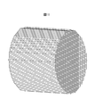
- FIG. 11 is a diagram conceptually showing (part) of the virtual cells set for the coil spring.
- Coil springs wound at an equal pitch are in a uniform stress state in the length direction of the strands. For this reason, the length direction of the strand was not partitioned by virtual cells.
- the cross section of the strand was finely divided so that the stress at the position can be reproduced in each virtual cell. Since 3409 virtual cells are used for the coil spring of material A, the coil spring of material A is partitioned by 3409 virtual cells that are in the form of a spring.
- the stress distribution of each of these virtual cells and sub-virtual cells is uniform.
- the inclusion existence probability in the sub virtual cell is 1/3 times the inclusion existence probability in the virtual cell.
- Murakami's equation is an equation for estimating the fatigue limit, it has been found from the experimental results of the present inventors that it corresponds to a fatigue strength of about 10 8 to 10 10 times. It has also been confirmed that the change in fatigue strength after 10 8 to 10 10 times is extremely small and is several percent or less.
- the stress used for fatigue evaluation was the stress ratio and amplitude of the maximum principal stress.
- the state of stress distribution inside the coil spring is the stress that can be estimated by the coil spring whirl theory as the fluctuating stress generated inside the coil spring under repeated load, the residual stress due to shot peening as the static stress, and the length of the coil spring.
- the torsional stress corresponding to the load necessary to fix the thickness can be added up and calculated.
- FIG. 12 is a diagram showing the fatigue strength excess probability pfV of the entire coil springs of materials A and B estimated under the above conditions, and the experimental results (probability of fatigue failure of 500 million times) of each coil spring.
- the solid line is the fatigue strength excess probability pfV of the entire coil spring of material A
- the white circle is the experimental result (500 million fatigue failure probability) of the coil spring of material A.
- the broken line is the fatigue strength excess probability pfV of the entire coil spring of material B
- the black circle is the experimental result (probability of fatigue failure of 500 million times) of the coil spring of material B.
- FIG. 12 it can be seen that the fatigue strength excess probability pfV of the whole coil spring and the experimental result are in good agreement.
- Example 2 Next, Example 2 will be described. In the present embodiment, a description will be given of a case where a rotating bending test is performed in which a tensile moment and a compressive force are repeatedly applied to the surface while a bending moment is applied.
- a round bar test piece in which compressive residual stress was introduced into the surface by shot peening was used as a machine part.
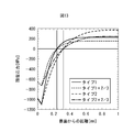
- FIG. 13 is a graph showing the relationship between the distance (depth) from the surface of the round bar test piece and the stress amplitude of the residual stress of the round bar test piece.
- the residual stress near the surface layer of the round bar test piece was measured, and the residual stress pattern inside the round bar test piece was determined from the measured residual stress near the surface layer.
- the residual stress patterns are five patterns in which the magnitude and depth distribution of the residual stress are changed, and one of them is assumed to have no residual stress.
- the iron part was melt
- 100 inclusions having an inclusion size ⁇ area of 20 [ ⁇ m] or more were extracted.
- a distribution function of inclusion size ⁇ area an approximate function was obtained by a maximum likelihood method using a beta distribution of general Pareto distribution as an extreme value statistical function.
- the test stress stress amplitude on the surface of the test piece
- the embodiment of the present invention described above can be realized by a computer executing a program. Further, a computer-readable recording medium in which the program is recorded and a computer program product such as the program can also be applied as an embodiment of the present invention.
- the recording medium for example, a flexible disk, a hard disk, an optical disk, a magneto-optical disk, a CD-ROM, a magnetic tape, a nonvolatile memory card, a ROM, or the like can be used.
- the embodiments of the present invention described above are merely examples of implementation in carrying out the present invention, and the technical scope of the present invention should not be construed as being limited thereto. Is. That is, the present invention can be implemented in various forms without departing from the technical idea or the main features thereof.
- the present invention can be used, for example, for designing and manufacturing machine parts and estimating the cause of destruction of machine parts.
Landscapes
- Physics & Mathematics (AREA)
- Engineering & Computer Science (AREA)
- General Physics & Mathematics (AREA)
- Theoretical Computer Science (AREA)
- Computer Hardware Design (AREA)
- Evolutionary Computation (AREA)
- Geometry (AREA)
- General Engineering & Computer Science (AREA)
- Health & Medical Sciences (AREA)
- Life Sciences & Earth Sciences (AREA)
- Chemical & Material Sciences (AREA)
- Analytical Chemistry (AREA)
- Biochemistry (AREA)
- General Health & Medical Sciences (AREA)
- Immunology (AREA)
- Pathology (AREA)
- Investigating Strength Of Materials By Application Of Mechanical Stress (AREA)
Abstract
Priority Applications (5)
| Application Number | Priority Date | Filing Date | Title |
|---|---|---|---|
| EP13797991.0A EP2772746B1 (fr) | 2012-05-29 | 2013-05-13 | Dispositif d'évaluation de rupture de composant, procédé d'évaluation de rupture de composant, et programme informatique |
| KR1020147008922A KR101461858B1 (ko) | 2012-05-29 | 2013-05-13 | 부품의 파괴 평가 장치, 부품의 파괴 평가 방법 및 컴퓨터 프로그램이 기록된 컴퓨터 판독 가능한 기록 매체 |
| US14/344,220 US9069917B2 (en) | 2012-05-29 | 2013-05-13 | Component fracture evaluation device, component fracture evaluation method and computer program |
| CN201380003346.0A CN103890560B (zh) | 2012-05-29 | 2013-05-13 | 部件的破坏评价装置、部件的破坏评价方法 |
| JP2013547773A JP5445727B1 (ja) | 2012-05-29 | 2013-05-13 | 部品の破壊評価装置、部品の破壊評価方法、及びコンピュータプログラム |
Applications Claiming Priority (2)
| Application Number | Priority Date | Filing Date | Title |
|---|---|---|---|
| JP2012122295 | 2012-05-29 | ||
| JP2012-122295 | 2012-05-29 |
Publications (1)
| Publication Number | Publication Date |
|---|---|
| WO2013179877A1 true WO2013179877A1 (fr) | 2013-12-05 |
Family
ID=49673081
Family Applications (1)
| Application Number | Title | Priority Date | Filing Date |
|---|---|---|---|
| PCT/JP2013/063286 Ceased WO2013179877A1 (fr) | 2012-05-29 | 2013-05-13 | Dispositif d'évaluation de rupture de composant, procédé d'évaluation de rupture de composant, et programme informatique |
Country Status (6)
| Country | Link |
|---|---|
| US (1) | US9069917B2 (fr) |
| EP (1) | EP2772746B1 (fr) |
| JP (1) | JP5445727B1 (fr) |
| KR (1) | KR101461858B1 (fr) |
| CN (1) | CN103890560B (fr) |
| WO (1) | WO2013179877A1 (fr) |
Cited By (3)
| Publication number | Priority date | Publication date | Assignee | Title |
|---|---|---|---|---|
| JP2017207488A (ja) * | 2016-05-17 | 2017-11-24 | 東芝機械株式会社 | 鋳鉄材料の疲労強度を予測する方法 |
| WO2022038840A1 (fr) * | 2020-08-17 | 2022-02-24 | 株式会社日立製作所 | Dispositif d'évaluation de progression de fissure et programme d'évaluation de progression de fissure |
| CN115034092A (zh) * | 2022-08-09 | 2022-09-09 | 中国航发北京航空材料研究院 | 含夹杂物的粉末高温合金低周疲劳寿命的预测方法 |
Families Citing this family (10)
| Publication number | Priority date | Publication date | Assignee | Title |
|---|---|---|---|---|
| JP6215446B2 (ja) * | 2014-03-03 | 2017-10-18 | 株式会社日立製作所 | 機械の材料疲労の表示方法、及びその装置 |
| JP6780575B2 (ja) * | 2017-04-27 | 2020-11-04 | 日本製鉄株式会社 | 疲労限度を予測する方法及びコンピュータプログラム |
| GB2565528B (en) * | 2017-06-20 | 2022-04-13 | Verderg Pipe Tech Ltd | Method of designing a pipe joint for use in a subsea pipeline |
| DE102017127276A1 (de) * | 2017-08-30 | 2019-02-28 | Taiwan Semiconductor Manufacturing Co., Ltd. | Standardzellen und abwandlungen davon innerhalb einer standardzellenbibliothek |
| CN109522569B (zh) * | 2017-09-19 | 2022-10-04 | 浙江大学 | 基于Weibull方程和残余变形的混凝土疲劳寿命预测方法和装置 |
| JP7059050B2 (ja) * | 2018-03-09 | 2022-04-25 | 三菱重工業株式会社 | 応力推定装置、応力推定方法およびプログラム |
| CN109142663B (zh) * | 2018-08-27 | 2021-03-26 | 佛山科学技术学院 | 一种高强度钢抗超高周疲劳机械加工表面评价方法 |
| EP4239313B1 (fr) * | 2020-12-03 | 2025-10-08 | JFE Steel Corporation | Procédé et programme d'évaluation de caractéristique de cassure retardée |
| CN116090138B (zh) * | 2023-04-03 | 2023-06-27 | 浙江远算科技有限公司 | 一种基于数据监测的水轮机转轮疲劳仿真计算方法和系统 |
| CN117349947B (zh) * | 2023-12-04 | 2024-03-15 | 中交长大桥隧技术有限公司 | 一种基于sn曲线与svm的结构安全智慧监测方法 |
Citations (3)
| Publication number | Priority date | Publication date | Assignee | Title |
|---|---|---|---|---|
| JPS63194279A (ja) | 1987-02-06 | 1988-08-11 | Nec Corp | 電子写真式記録装置 |
| JP2010256351A (ja) | 2009-04-01 | 2010-11-11 | Nippon Steel Corp | 部材の疲労破壊確率推定装置、部材の疲労破壊確率推定方法、及びコンピュータプログラム |
| JP2012073059A (ja) * | 2010-09-28 | 2012-04-12 | Ntn Corp | 超音波軸荷重疲労試験による高強度鋼中アルミナ系介在物の検査方法 |
Family Cites Families (9)
| Publication number | Priority date | Publication date | Assignee | Title |
|---|---|---|---|---|
| KR19990054619A (ko) * | 1997-12-26 | 1999-07-15 | 유무성 | 피로시험장치 및 피로시험방법 |
| KR100324900B1 (ko) * | 1999-05-25 | 2002-02-28 | 조양호 | 피로수명 예측 방법 |
| US6699335B2 (en) * | 2000-11-15 | 2004-03-02 | Nsk Ltd. | Machine part |
| US7117574B2 (en) * | 2002-03-15 | 2006-10-10 | Purdue Research Foundation | Determining expected fatigue life of hard machined components |
| US8116990B2 (en) * | 2007-10-19 | 2012-02-14 | Ashok Koul | Method and system for real-time prognosis analysis and usage based residual life assessment of turbine engine components and display |
| ES2677594T3 (es) * | 2007-11-12 | 2018-08-03 | Nippon Steel & Sumitomo Metal Corporation | Método para producir conductos comunes y conductos comunes parcialmente reforzados |
| US8794215B2 (en) * | 2009-03-12 | 2014-08-05 | Nippon Steel & Sumitomo Metal Corporation | Method of producing common rail and common rail |
| JP2011243790A (ja) * | 2010-05-19 | 2011-12-01 | Panasonic Electric Works Co Ltd | 配線方法、並びに、表面に配線が設けられた構造物、半導体装置、配線基板、メモリカード、電気デバイス、モジュール及び多層回路基板 |
| US8688418B2 (en) * | 2011-09-01 | 2014-04-01 | Mcmoran Oil & Gas, Llc | Engineered methodology for design verification and validation of ultra-deep high pressure high temperature oil and gas well control equipment |
-
2013
- 2013-05-13 WO PCT/JP2013/063286 patent/WO2013179877A1/fr not_active Ceased
- 2013-05-13 EP EP13797991.0A patent/EP2772746B1/fr not_active Not-in-force
- 2013-05-13 US US14/344,220 patent/US9069917B2/en not_active Expired - Fee Related
- 2013-05-13 JP JP2013547773A patent/JP5445727B1/ja active Active
- 2013-05-13 CN CN201380003346.0A patent/CN103890560B/zh not_active Expired - Fee Related
- 2013-05-13 KR KR1020147008922A patent/KR101461858B1/ko not_active Expired - Fee Related
Patent Citations (3)
| Publication number | Priority date | Publication date | Assignee | Title |
|---|---|---|---|---|
| JPS63194279A (ja) | 1987-02-06 | 1988-08-11 | Nec Corp | 電子写真式記録装置 |
| JP2010256351A (ja) | 2009-04-01 | 2010-11-11 | Nippon Steel Corp | 部材の疲労破壊確率推定装置、部材の疲労破壊確率推定方法、及びコンピュータプログラム |
| JP2012073059A (ja) * | 2010-09-28 | 2012-04-12 | Ntn Corp | 超音波軸荷重疲労試験による高強度鋼中アルミナ系介在物の検査方法 |
Non-Patent Citations (8)
| Title |
|---|
| "MURAKAMI Yukitaka", 25 December 2008, YOKENDO, article "Metal Fatigue; Effects of small defects and inclusions" |
| ANDERSON C W ET AL.: "The precision of methods using the statistics of extremes for the estimation of the maximum size of inclusions in clean steels.", ACTA MATER, vol. 48, no. 17, 8 November 2000 (2000-11-08), pages 4235 - 4246, XP055131417 * |
| HIROSHI SHIMANUKI: "Jikuukeko SUJ2 no Giga Cycle Hiro Tokusei ni Oyobosu Kaizaibutsu Sunpo no Eikyo", CURRENT ADVANCES IN MATERIALS AND PROCESSES (CD-ROM), vol. 23, no. 2, 1 September 2010 (2010-09-01), pages ROMBUNNO.404, XP008171239 * |
| HU CHAO ET AL.: "Locally enhanced Voronoi cell finite element model (LE-VCFEM) for simulating evolving fracture in ductile microstructures containing inclusions", INT J NUMER METHODS ENG, vol. 76, no. 12, 17 December 2008 (2008-12-17), pages 1955 - 1992, XP055131418 * |
| MATSUMOTO: "Effect of inclusion on rotating bending fatigue strength of carburized and shot-peened steels for gear use", PROCEEDINGS OF THE JAPAN SOCIETY OF MECHANICAL ENGINEERS CONFERENCE ON MATERIAL MECHANICS, 1990, pages 275,277 |
| See also references of EP2772746A4 |
| SHIMANUKI H.: "Effect of Inclusion Size on Giga-Cycle Fatigue Properties of SUJ2", CAMP-ISIJ, 2010, pages 688 |
| ZHANG J.M. ET AL.: "Estimation of maximum inclusion size and fatigue strength in high-strength ADF1 steel", MATER SCI ENG A STRUCT MATER PROP MICROSTRUCT PROCESS, vol. A394, no. 1/2, 15 March 2005 (2005-03-15), pages 126 - 131, XP004784389 * |
Cited By (5)
| Publication number | Priority date | Publication date | Assignee | Title |
|---|---|---|---|---|
| JP2017207488A (ja) * | 2016-05-17 | 2017-11-24 | 東芝機械株式会社 | 鋳鉄材料の疲労強度を予測する方法 |
| WO2022038840A1 (fr) * | 2020-08-17 | 2022-02-24 | 株式会社日立製作所 | Dispositif d'évaluation de progression de fissure et programme d'évaluation de progression de fissure |
| JP2022033464A (ja) * | 2020-08-17 | 2022-03-02 | 株式会社日立製作所 | き裂進展評価装置、及びき裂進展評価プログラム |
| JP7429619B2 (ja) | 2020-08-17 | 2024-02-08 | 株式会社日立製作所 | き裂進展評価装置、及びき裂進展評価プログラム |
| CN115034092A (zh) * | 2022-08-09 | 2022-09-09 | 中国航发北京航空材料研究院 | 含夹杂物的粉末高温合金低周疲劳寿命的预测方法 |
Also Published As
| Publication number | Publication date |
|---|---|
| US9069917B2 (en) | 2015-06-30 |
| EP2772746A1 (fr) | 2014-09-03 |
| CN103890560A (zh) | 2014-06-25 |
| CN103890560B (zh) | 2015-11-25 |
| JPWO2013179877A1 (ja) | 2016-01-18 |
| EP2772746B1 (fr) | 2017-07-05 |
| EP2772746A4 (fr) | 2014-11-26 |
| JP5445727B1 (ja) | 2014-03-19 |
| KR20140066749A (ko) | 2014-06-02 |
| KR101461858B1 (ko) | 2014-11-13 |
| US20140350904A1 (en) | 2014-11-27 |
Similar Documents
| Publication | Publication Date | Title |
|---|---|---|
| JP5445727B1 (ja) | 部品の破壊評価装置、部品の破壊評価方法、及びコンピュータプログラム | |
| Nicoletto et al. | Characterization of microshrinkage casting defects of Al–Si alloys by X-ray computed tomography and metallography | |
| Banvillet et al. | Fatigue life under non-Gaussian random loading from various models | |
| JP5059224B2 (ja) | 部品の疲労破壊評価装置、部品の疲労破壊評価方法、及びコンピュータプログラム | |
| JP2010256351A (ja) | 部材の疲労破壊確率推定装置、部材の疲労破壊確率推定方法、及びコンピュータプログラム | |
| Costa et al. | A new method for prediction of nodular cast iron fatigue limit | |
| JP5710997B2 (ja) | 疲労限度特定システムおよび疲労限度特定方法 | |
| JP7705044B2 (ja) | 疲労評価方法及び疲労評価プログラム | |
| CN106383052A (zh) | 一种考虑夹杂的金属疲劳载荷下薄弱区域确定方法 | |
| JP2009092652A (ja) | 金属材料の余寿命評価方法及び変形量評価方法 | |
| McMurtrey et al. | Fracture mechanics modelling of constant and variable amplitude fatigue behaviour of field corroded 7075‐T6511 aluminium | |
| JP6982847B2 (ja) | 破壊現象の解析装置、破壊現象の解析方法、及びプログラム | |
| Zhang et al. | A fully numerical life prediction framework for notched structures under different types of creep-fatigue loadings and damage mechanisms | |
| Yang et al. | Existence and insufficiency of the crack closure for fatigue crack growth analysis | |
| Lu et al. | Experimental investigation of random loading sequence effect on fatigue crack growth | |
| Lipski | Determination of the SN curve and the fatigue limit by means of the thermographic method for ductile cast iron | |
| Li et al. | Computational Prediction of Total Fatigue Life With an Integrated Approach | |
| Baxevanakis et al. | Data-driven damage model based on nondestructive evaluation | |
| Kumar et al. | Methodology for application of damage mechanics approach to model high temperature fatigue damage evolution in a turbine disc superalloy | |
| JP2024529337A (ja) | 繊維試料の疲労評価 | |
| Khellafi et al. | Finite element based fatigue analysis of 6082 Aluminum alloy under random loading | |
| JP2020176855A (ja) | 非破壊評価方法および非破壊評価システム | |
| Golden et al. | Confidence bound estimation for mechanism-based small crack growth probabilistic design life predictions | |
| RU2439532C2 (ru) | Способ определения долговечности образцов из композиционных материалов при циклическом нагружении | |
| JP2024137163A (ja) | 疲労評価方法及び疲労評価プログラム |
Legal Events
| Date | Code | Title | Description |
|---|---|---|---|
| ENP | Entry into the national phase |
Ref document number: 2013547773 Country of ref document: JP Kind code of ref document: A |
|
| 121 | Ep: the epo has been informed by wipo that ep was designated in this application |
Ref document number: 13797991 Country of ref document: EP Kind code of ref document: A1 |
|
| WWE | Wipo information: entry into national phase |
Ref document number: 14344220 Country of ref document: US |
|
| REEP | Request for entry into the european phase |
Ref document number: 2013797991 Country of ref document: EP |
|
| WWE | Wipo information: entry into national phase |
Ref document number: 2013797991 Country of ref document: EP |
|
| ENP | Entry into the national phase |
Ref document number: 20147008922 Country of ref document: KR Kind code of ref document: A |
|
| NENP | Non-entry into the national phase |
Ref country code: DE |