WO2013180145A1 - Tendeur - Google Patents
Tendeur Download PDFInfo
- Publication number
- WO2013180145A1 WO2013180145A1 PCT/JP2013/064812 JP2013064812W WO2013180145A1 WO 2013180145 A1 WO2013180145 A1 WO 2013180145A1 JP 2013064812 W JP2013064812 W JP 2013064812W WO 2013180145 A1 WO2013180145 A1 WO 2013180145A1
- Authority
- WO
- WIPO (PCT)
- Prior art keywords
- guide
- propulsion
- propelling
- tensioner
- guide hole
- Prior art date
- Legal status (The legal status is an assumption and is not a legal conclusion. Google has not performed a legal analysis and makes no representation as to the accuracy of the status listed.)
- Ceased
Links
Images










Classifications
-
- F—MECHANICAL ENGINEERING; LIGHTING; HEATING; WEAPONS; BLASTING
- F16—ENGINEERING ELEMENTS AND UNITS; GENERAL MEASURES FOR PRODUCING AND MAINTAINING EFFECTIVE FUNCTIONING OF MACHINES OR INSTALLATIONS; THERMAL INSULATION IN GENERAL
- F16H—GEARING
- F16H7/00—Gearings for conveying rotary motion by endless flexible members
- F16H7/08—Means for varying tension of belts, ropes or chains
- F16H7/0848—Means for varying tension of belts, ropes or chains with means for impeding reverse motion
-
- F—MECHANICAL ENGINEERING; LIGHTING; HEATING; WEAPONS; BLASTING
- F16—ENGINEERING ELEMENTS AND UNITS; GENERAL MEASURES FOR PRODUCING AND MAINTAINING EFFECTIVE FUNCTIONING OF MACHINES OR INSTALLATIONS; THERMAL INSULATION IN GENERAL
- F16H—GEARING
- F16H7/00—Gearings for conveying rotary motion by endless flexible members
- F16H7/08—Means for varying tension of belts, ropes or chains
- F16H2007/0802—Actuators for final output members
- F16H2007/0806—Compression coil springs
-
- F—MECHANICAL ENGINEERING; LIGHTING; HEATING; WEAPONS; BLASTING
- F16—ENGINEERING ELEMENTS AND UNITS; GENERAL MEASURES FOR PRODUCING AND MAINTAINING EFFECTIVE FUNCTIONING OF MACHINES OR INSTALLATIONS; THERMAL INSULATION IN GENERAL
- F16H—GEARING
- F16H7/00—Gearings for conveying rotary motion by endless flexible members
- F16H7/08—Means for varying tension of belts, ropes or chains
- F16H7/0848—Means for varying tension of belts, ropes or chains with means for impeding reverse motion
- F16H2007/0853—Ratchets
Definitions
- the present invention relates to a tensioner used to keep the tension of an endless belt or chain constant.
- the tensioner for example, presses a timing chain or timing belt used in an automobile engine with a predetermined force, and acts to keep the tension constant when the chain is stretched or loosened.
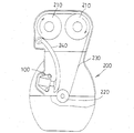
- FIG. 32 shows a state in which the tensioner 100 is mounted on the engine body 200 of the automobile.
- a pair of cam sprockets 210 and 210 and a crank sprocket 220 are arranged inside the engine body 200, and a timing chain 230 is stretched between the sprockets 210, 210 and 220 in an endless manner.
- a chain guide 240 is swingably disposed on the moving path of the timing chain 230, and the timing chain 230 slides on the chain guide 240.
- the engine body 200 is filled with lubricating oil (not shown).
- the tensioner 100 is fixed inside the engine body 200 to press the chain guide 240, and tension is applied to the timing chain 230 by the pressing.
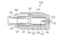
- FIG. 33 shows a tensioner 100 conventionally used.
- a thrust member 130 is formed by a cylindrical body extending in the axial direction, and the thrust member 130 is assembled to move forward and backward with respect to the case 110.
- the chain guide 240 is pressed. It is.
- the propulsion member 130 has a female thread portion 131 formed on the inner peripheral surface thereof, and the male screw portion 121 is screwed into the female thread portion 131 so that the rotating member 120 is assembled to the propulsion member 130, and these are integrated into the case 110. Is housed.
- the rotating member 120 is urged to rotate by the elastic member 150, and the propelling member 130 advances from the case 110 by the rotation of the rotating member 120.
- the elastic member 150 uses a torsion spring, and the hook portion 151 on one end side is locked to the case 110, and the hook portion 152 on the other end side is inserted into the rotating member 120 and locked to rotate the rotating member 120. The rotation is energized.
- the propelling member 130 is rotationally restrained by the bearing 160, and the rotating member 120 moves forward in this rotationally restrained state to advance from the case 110, and the reaction force from the timing chain 230 acts to retract to the case 110 side.
- the bearing 160 is fixed to the tip portion of the case 110, and the propelling member 130 passes through the sliding hole 161.
- the inner surface of the sliding hole 161 and the outer surface of the propelling member 130 are formed in an oval shape, a parallel cut, or other non-circular shape, whereby the propelling member 130 is rotationally restrained and linearly moves back and forth.
- a cylindrical spacer 170 is disposed outside the rotating member 120.
- the spacer 170 has a front end faced to the bearing 160, and when the spacer 170 comes into contact with the bearing 160, the propulsion member 130 is prevented from advancing, and the propulsion member 130 is prevented from falling off the case 110.
- Reference numeral 140 denotes a stopper member, which is inserted into the case 110 through an opening 112 formed at the right end portion of the case 110, and the distal end portion of the insertion enters a stopper slit 124 formed in the bottom wall surface 123 of the rotating member 120 and rotates. Engage with member 120. Since the rotation of the rotating member 120 is locked by the engagement of the stopper member 140, delivery, mounting to the engine body 200, and the like can be performed in this state.
- the rotating member 120 is rotated by the urging force of the elastic member 150, and this rotating force is converted into the propelling force of the propelling member 130, so that the propelling member 130 advances from the case 110.
- the propulsion member 130 presses the timing chain 230 via the chain guide 240, so that the tension of the timing chain 230 can be applied.
- the tensioner is not limited to the tensioner 100 shown in FIG. 33, and the propelling member 130 is retracted to the tail and temporarily fixed, delivered in this temporarily fixed state, and mounted on the engine body 200. Accordingly, it is necessary to temporarily fix the propelling member 130 in a retracted state, and structures for that purpose are described in Patent Documents 1 to 4.
- the tensioner of Patent Document 1 uses a stopper member (reference numeral 50 in Patent Document 1) similar to the stopper member 140 of FIG. 33.
- the rotation of the rotating member is locked by the stopper member, and the propulsion member is retracted indirectly. The state is retained.
- the stopper member is removed and the lock is released to bring it into an operating state.
- the tensioner disclosed in Patent Document 2 has a structure in which a torsion spring (reference numeral 10 in Patent Document 2) is wound and locked around a rotating member, thereby holding the propelling member in a retracted state.
- an annular locking groove (12b in Patent Document 3) is formed in the propelling member, and a locking pin (reference S in Patent Document 3) is passed through the case to engage with the locking groove.
- the structure is such that the propulsion member is retracted and stopped.
- an extension piece (reference numeral 12 in Patent Document 4) is extended from the case toward the propulsion member, and a stopper pin (reference numeral 15 in Patent Document 4) is inserted between the extension piece and the propulsion member.
- the propulsion member is kept in the retracted state.
- a spacer (reference numeral 101 in Patent Document 1) is arranged outside the rotating member, and the spacer prevents the propulsion member from falling out of the case.
- a retaining piece (reference numeral 21 in Patent Document 2) is attached to the rear end portion of the propelling member, and the retaining member is brought into contact with the case, so that the advancement of the propelling member is stopped and the falling is prevented. It has a structure.
- the present invention has been made in consideration of such problems of the conventional tensioner, and an object of the present invention is to provide a tensioner capable of temporarily fixing the propulsion member and preventing it from coming off with a simple structure. .
- the tensioner of the present invention is capable of moving forward and backward in the axial direction with respect to the support member, and propels a propelling member that presses the mating member by advancing in the axial direction and an axial load for the propelling member to advance.
- An elastic member that acts directly or indirectly on the member, a guide member that is formed in an elongated shape extending in the axial direction of the propulsion member, and is disposed so as to move forward and backward along the axial direction of the propulsion member;
- a guide hole formed in the guide member so as to extend along the axial direction of the propulsion member in a state where both ends of the direction are closed, at least one engagement recess formed in the guide hole, and the guide hole
- the guide member is provided in the support member so as to be relatively slidable while being inserted into the interior of the support member, and the forward and backward movement of the propulsion member is locked through the guide member by engagement with the engagement recess,
- the disengagement of the serial engaging recess characterized
- the support member includes a holding member that accommodates the propelling member so as to be movable back and forth, and a fixing bracket that holds the holding member, and the engaging convex portion is provided on the fixing bracket. It is preferable. Further, it is preferable that the engaging convex portion is extracted to the outside of the guide hole, and the extraction end portion is a retaining piece that is wider than the width of the guide hole. Moreover, it is preferable that the engaging recess is formed at an end of the guide hole on the advancing direction side of the propulsion member. Further, it is preferable that the engaging recess is formed at an end portion on the advance direction side and an end portion on the reverse direction side of the propulsion member in the guide hole.
- the guide member is coupled to the propulsion member so as to be movable forward and backward integrally with the propulsion member.
- the propulsion member penetrates the guide member so as to be relatively movable, and a connecting means is provided for connecting the propulsion member and the guide member when the propulsion member moves in the advance direction.
- a plurality of the guide holes are formed in the guide member, and the engaging convex portions are provided corresponding to the plurality of guide holes, respectively.
- a plurality of recesses for engagement are formed in the guide hole, and the protrusions for engagement are engageable at the positions of the plurality of recesses for engagement.
- another tensioner of the present invention can move forward and backward in the axial direction with respect to the support member, and a propelling member that presses the mating member by advancing in the axial direction, and a shaft for the propelling member to advance
- An elastic member that causes a directional load to act directly or indirectly on the propulsion member, an elongated shape that extends in the axial direction of the propulsion member, and can move forward and backward integrally with the propulsion member;
- a screw member that locks the forward and backward movement of the propulsion member and allows the forward and backward movement by loosening the tightening.
- the engaging member provided on the support member is engaged with the engaging recessed portion of the guide hole so that the propelling member is locked via the guide member, so that the propelling member is temporarily fixed. be able to.
- the engaging convex portion provided on the propulsion member is located inside the guide hole whose both ends in the length direction are closed, the propulsion member does not fall off from the support member. Therefore, the propulsion member can be temporarily fixed and prevented from falling off with a simple structure. Furthermore, since there is no need to discard a part for temporarily fixing the propulsion member, the part is not wasted.
- the screw member is provided through the guide hole, and the propulsion member is locked by tightening the screw member, so that the propulsion member can be temporarily fixed. Further, since the screw member passes through the guide hole whose both ends in the length direction are closed, the propulsion member does not fall out of the support member. Therefore, the propulsion member can be temporarily fixed and prevented from falling off with a simple structure. Furthermore, since there is no need to discard a part for temporarily fixing the propulsion member, the part is not wasted.
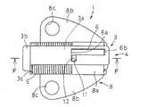
- FIG. 5 is a sectional view taken along line FF in FIG. 2.
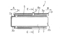
- FIG. 4 is a sectional view taken along line EE in FIG. 3.
- the guide member of 1st Embodiment is shown, (a) is a top view, (b) is a GG sectional view, (c) is a left view.
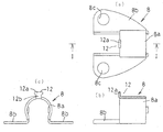
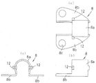
- the bracket for fixation of a 1st embodiment is shown, (a) is a top view, (b) is a HH line sectional view, and (c) is a left side view.
- FIG. 12 is a sectional view taken along line JJ in FIG. 11.
- the propulsion member of 3rd Embodiment is shown, (a) is a top view, (b) is a left view.
- the guide member of 3rd Embodiment is shown, (a) is a top view, (b) is KK sectional view, (c) is a left view. It is a perspective view at the time of the action
- FIG. 18 is a sectional view taken along line MM in FIG.
- the bracket for fixation of 4th Embodiment is shown, (a) is a top view, (b) is a front view, (c) is a left view.
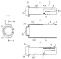
- the guide member of 4th Embodiment is shown, (a) is a front view, (b) is a NN sectional view, (c) is a rear view, (d) is a left view.
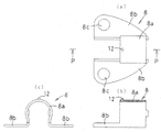
- the bracket for fixation of 5th Embodiment is shown, (a) is a top view, (b) is a PP line sectional drawing, (c) is a left view.
- FIG. 29 is a sectional view taken along line RR in FIG. 28. It is a left view of FIG. 28. It is sectional drawing which shows the tensioner of the deformation
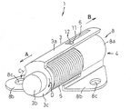
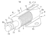
- (First embodiment) 1 to 6 show a tensioner 1 according to a first embodiment of the present invention.
- the tensioner 1 includes a propelling member 2, a guide member 3, a support member 4, and an elastic member 5.
- a guide hole 6 is formed in the guide member 3.
- the propulsion member 2 is composed of a single-diameter shaft, and moves forward and backward along the axial direction (longitudinal direction).
- the left direction in FIGS. 2 and 3 is the advance direction A of the propulsion member 2, and the right direction is the backward direction B of the propulsion member 2, and the propulsion member 2 presses the mating member when the propulsion member 2 advances in the advance direction A.
- the tensioner 1 is used in an engine body for an automobile
- the counterpart member is a timing chain 230 or a timing belt 240 (see FIG. 32) wound endlessly in the engine body 200.
- the propelling member 2 is accommodated in a holding member 7 that is a constituent member of the support member 4, and can move forward and backward within the holding member 7.
- the guide member 3 includes a plate-shaped guide main body portion 3a extending in the same direction as the axial direction of the propelling member 2, and the advancing direction A of the propelling member 2 in the guide main body portion 3a.
- the bottomed fixing cylinder 3b integrally formed on the side and the guide main body 3a and the fixing cylinder 3b are bent at right angles from the guide main body 3a toward the fixing cylinder 3b. Formed by the flange portion 3c.
- the end portion 2a on the advancing direction A side of the propelling member 2 is inserted into the bottomed fixing cylinder portion 3b, and the propelling member 2 and the guide are clamped from the outer peripheral side of the fixing cylinder portion 3b in this inserted state.
- the member 3 is coupled. Accordingly, the guide member 3 moves forward and backward together with the propelling member 2. Further, since the propelling member 2 is integrated with the guide member 3 in this manner, the propelling member 2 is in a state in which the rotation with respect to the guide member 3 is restricted.
- the fixing cylinder portion 3b and the propelling member 2 can be coupled by using other means such as soldering, screwing, and screwing.
- the support member 4 is formed by the holding member 7 and the fixing bracket 8 described above.
- the holding member 7 has a cylindrical shape, and accommodates the propelling member 2 therein so as to be movable forward and backward.
- the fixing bracket 8 is attached to the holding member 7 by holding the holding member 7.
- the fixing bracket 8 is formed by a holding portion 8a for holding the holding member 7, and a pair of fixing portions 8b extending in a plate shape from the left and right sides of the holding portion 8a. Yes.
- the holding portion 8a has a substantially arc shape, and is attached to the holding member 7 in a holding state by being crimped with the holding member 7 accommodated therein.
- the pair of plate-like fixing portions 8b are for fixing the tensioner 1 to the engine main body 200, and fixing holes 8c for fixing the tensioner 1 to the engine main body 200 are formed.
- the fixing bracket 8 and the holding member 7 may be provided integrally or may be attached integrally.
- the elastic member 5 is composed of a compression coil spring, and applies an axial load for the propelling member 2 to propel. As shown in FIGS. 1 to 3, the elastic member 5 is disposed between one end of the elastic member 5 by contacting the flange portion 3c of the guide member 3 and the other end contacting the holding portion 8a of the fixing bracket 8. The guide member 3 is urged to move in the advance direction A. The propelling member 2 is coupled to the guide member 3, and the propelling member 2 is indirectly applied with an axial load in the advancing direction via the guide member 3 by the biasing of the elastic member 5 to the guide member 3.
- the guide hole 6 is formed in the guide body 3 a of the guide member 3 so as to extend along the axial direction of the propulsion member 2.
- the guide hole 6 is formed in the guide main body 3a so as to be positioned on the side of the propelling member 2 in the backward direction B.
- the guide hole 6 is a closed space in which both end portions 6a and 6b in the length direction are closed.
- the end 6a on one side in the length direction of the guide hole 6 will be described as a start end 6a, and the other end 6b will be described as a termination 6b.
- An engaging recess 11 is formed in the guide hole 6.
- the engaging recess 11 is formed so as to communicate with the guide hole 6 at an end of the guide hole 6 on the advancing direction A side of the propelling member 2 (starting end 6 a of the guide hole 6), and together with the guide hole 6, the guide member 3. Is provided.
- the engaging recess 11 communicates with the guide hole 6 so as to be orthogonal to the length direction of the guide hole 6.
- the engaging recess 11 in this embodiment is formed corresponding to the position where the elastic member 5 is kept in the maximum compression state.
- the engaging convex part 12 is provided with respect to the engaging concave part 11. As shown in FIGS. 1 to 4 and 6, the engaging convex portion 12 is provided on the fixing bracket 8 of the support member 4, and is substantially from the top of the substantially arc-shaped holding portion 8 a in the fixing bracket 8. It is formed in a U shape so as to protrude upward.
- the engaging convex portion 12 is provided corresponding to the guide hole 6 and the engaging concave portion 11, and can be engaged with and disengaged from the engaging concave portion 11, and is provided inside the guide hole 6.
- the guide member 3 is slidable relative to the engaging convex portion 12.
- the guide member 3 When the engaging convex portion 12 engages with the engaging concave portion 11, the guide member 3 is engaged with the fixing bracket 8, and the forward and backward movement of the guide member 3 with respect to the fixing bracket 8 is locked.
- the engaging convex portion 12 is disengaged from the engaging concave portion 11, the engaging convex portion 12 enters the guide hole 6 of the guide member 3, so that the forward / backward movement of the guide member 3 is locked. It is released to allow the member 3 to move forward and backward. At this time, the guide member 3 moves forward and backward while sliding with respect to the engaging convex portion 12 on the fixed side.
- the guide member 3 is slid in the backward direction B.
- the propelling member 2 is retracted in the same direction and the elastic member 5 is compressed.
- the engaging convex portion 12 of the fixing bracket 8 is located at the position facing the start end portion 6 a of the guide hole 6. Thereafter, by rotating the guide member 3 in the direction of arrow C in FIG. 1 (counterclockwise in FIG. 1), the engaging concave portion 11 of the guide member 3 engages with the engaging convex portion 12 of the fixing bracket 8.
- the guide member 3 is rotated in the direction of arrow D in FIG.
- the engaging convex portion 12 is disengaged from the engaging concave portion 11 and enters the guide hole 6. Accordingly, the lock of the guide member 3 is released, and the forward / backward movement is allowed.
- the propelling member 2 advances together with the guide member 3 due to the axial load of the elastic member 5 acting on the guide member 3, and presses the chain guide 240 (see FIG. 32) in the engine body 200. Appropriate tension can be applied to the timing chain 230.
- the guide hole 6 provided in the guide member 3, the engagement concave portion 11 provided in the guide hole 6, and the engagement convex portion 12 provided in the fixing bracket 8 of the support member 4 are supported. It is possible to temporarily fix the propelling member 2 to the member 4 (fixing bracket 8) and prevent it from falling off. Therefore, the number of parts is small, the structure is simple, and the assembly is easy. Moreover, since it is not necessary to discard the part for temporarily fixing the propelling member 2, the part is not wasted.
- the dimension of the engaging convex part 12 on the fixing bracket 8 side and the width of the guide hole 6 on the guide member 3 side are set to dimensions that can restrict the rotation of the guide member 3.
- the rotation of the propulsion member 2 can be restricted. That is, in addition to the guide member 3 being restricted in rotation with respect to the fixing bracket 8 by the above dimension setting, the propelling member 2 and the guide member 3 are integrally coupled by caulking. Therefore, the rotation of the propelling member 2 can be restricted via the guide member 3. Accordingly, it is possible to cope with a case where regulation in the rotation direction is necessary.
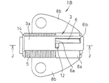
- (Second Embodiment) 7 to 9 show a tensioner 1A of the present invention.
- the tensioner 1A is different from the tensioner 1 of the first embodiment in that the engaging convex portion 12 provided in the fixing bracket 8 is changed and two engaging concave portions 11 and 15 are formed in the guide hole 6 of the guide member 3.
- Other configurations are the same as those of the tensioner 1 of the first embodiment.
- the fixing bracket 8 has a substantially arc-shaped holding portion 8 a for holding the holding member 7, and extends in a plate shape from the left and right sides of the holding portion 8 a and is fixed to the engine body 200.
- the engaging convex portion 12 is provided by projecting upward from the top of the substantially arc-shaped holding portion.
- the engaging convex portion 12 is formed by a leg portion 12b standing up from the holding portion 8a and a retaining piece portion 12a formed wide above the leg portion 12b.
- two engagement recesses 11 and 15 are formed in the guide hole 6 of the guide member 3.
- the engaging recess 11 is formed at the start end 6a of the guide hole 6 (the end of the propelling member 2 on the advancing direction A side), and the sub engaging recess 15 is the terminal end 6b of the guide hole 6 (retracting direction B of the propelling member 2) Each of which communicates with the guide hole 6 in a state orthogonal to the length direction of the guide hole 6.
- the engaging recesses 11 and 15 are engaged with the engaging protrusions 12 formed on the fixing bracket 8 so as to be freely disengaged.
- the engaging protrusions 12 are formed on the engaging recesses 11 on the start end 6a side. By engaging, the forward / backward movement of the guide member 3 is locked, and the engaging convex portion 12 engages with the sub engaging concave portion 15 on the terminal end portion 6b side, so that the propulsion member 2 and the guide member 3 at the time of tensioner assembly are engaged. Temporarily fix.
- the leg portion 12 b of the engaging convex portion 12 is inserted into a guide hole 6 formed in the guide main body portion 3 a of the guide member 3, and the guide member 3 slides with respect to the engaging convex portion 12.
- the retaining piece 12 a is extracted from the guide hole 6 to the outside of the guide member 3, and its width is wider than the guide hole 6. This prevents the guide hole 6 from coming out of the retaining piece 12 a and prevents the guide member 3 from floating from the fixing bracket 8.
- the guide member 3 is thin and the guide member 3 is not lifted even when an upward bending stress is applied. It is possible to prevent the bracket from coming off from the fixing bracket 8. Further, the engaging convex portion 12 is engaged with the sub engaging concave portion 15 of the terminal end portion 6b of the guide hole 6, so that the propelling member 2 and the guide member 3 are positioned temporarily when the tensioner 1A is assembled. I do. Thus, since the temporary fixation at the time of assembly can be performed, the tensioner 1A can be easily assembled.
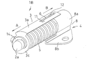
- (Third embodiment) 10 to 15 show a tensioner 1B according to a third embodiment of the present invention.
- the tensioner 1B is configured such that the propelling member 2 and the guide member 3 can be moved relative to the tensioner 1 of the first embodiment. That is, in the tensioner 1 of the first embodiment, the propulsion member 2 and the guide member 3 are joined together by caulking so that they are integrally moved forward and backward, whereas the tensioner of this embodiment is 1B has a separate structure in which the propulsion member 2 penetrates the guide member 3, so that they move synchronously only when the propulsion member 2 moves in the advance direction (direction A), and the propulsion member 2 moves backward. Only the guide member 3 can be retracted when moving in the (B direction).
- the guide member 3 is bent from the guide main body 3a extending in the same direction as the axial direction of the propelling member 2 and the end of the guide main body 3a on the advancing direction A side of the propelling member 2. Therefore, it has a flange portion 3b formed integrally with the guide member 3.
- the flange portion 3b is formed with a through-hole portion 3d penetrating in the thickness direction.
- the propulsion member 2 is slidably penetrated through the through hole 3d.
- the propelling member 2 has a main body portion 2c extending in the axial direction, and a locking groove portion 2d formed in an end portion 2a on the advancing direction side of the main body portion 2c.
- the outer diameter of the main body portion 2c is slightly smaller than the inner diameter of the through hole portion 3d of the guide member 3, and when the propulsion member 2 passes through the through hole portion 3d, the propulsion member 2 and the guide member 3 are in the axial direction. It can move freely in the direction of rotation.
- the propulsion member 2 is assembled to the guide member 3 so that the locking groove 2d is pulled out of the through hole 3d. Then, as shown in FIGS. 10 to 12 and 15, a retaining ring 14 as a connecting means is fitted into and fixed to the locking groove 2d (through end of the propelling member 2) that has come out of the through hole 3d. .
- the retaining ring 14 is sized to contact the flange portion 3c of the guide member 3, and the guide member 3 and the propelling member 2 are connected in a state of being prevented from coming off by this contact.
- the elastic member 5 is disposed between the flange portion 3c of the guide member 3 and the holding portion 8a of the fixing bracket 8 (see FIG. 12), and the axial load for the propelling member 2 to advance Is applied to the propelling member 2 via the guide member 3.
- the guide member 3 is rotated in the direction of arrow D (see FIG. 1) in the same manner as in the first embodiment to release the engagement between the engaging convex portion 12 and the engaging concave portion 11.
- the guide member 3 advances due to the axial load of the elastic member 5 acting on the guide member 3.
- the propulsion member 2 to which the retaining ring 14 is attached advances together with the guide member 3, and the propulsion member 2 moves to the chain guide 240 in the engine body 200. Press.
- an appropriate tension can be applied to the timing chain 230.
- the propulsion member 2 Since the axial load of the elastic member 5 that presses the guide member 3 does not act on the propulsion member 2, the propulsion member 2 stops in a state where it has advanced from the holding member 7 of the fixed side member 4. Thereby, the tensioner 1B can be easily removed from the engine body 200.
- the propulsion member 2 in the advanced state is not retracted in the B direction by only pressing in the axial direction, as in the sixth embodiment described later. Suitable for maintenance.
- the propulsion member 2 and the guide member 3 are relatively rotatable, and the rotation of the propulsion member 2 is not restricted.
- the illustration is omitted, but the propulsion member 2 penetrating the through hole portion 3d and the through hole portion 3d of the guide member 3 has an oval shape, a parallel cut shape, a polygonal shape, or the like.
- the non-circular shape is formed.
- the propulsion member 2 can move forward and backward relative to the guide member 3 in the axial direction and is restricted in rotation, so that it is possible to cope with a case where restriction in the rotation direction is required.
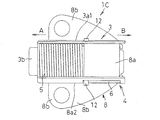
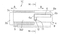
- (Fourth embodiment) 16 to 20 show a tensioner 1C according to a fourth embodiment of the present invention.
- the tensioner 1 ⁇ / b> C of this embodiment two guide holes 6 are formed in the guide member 3, and engaging convex portions 12 are provided in the respective guide holes 6.
- FIG. 20 shows the guide member 3 of this embodiment.
- the guide member 3 has two guide main body portions including a first guide main body portion 3a1 and a second guide main body portion 3a2. These guide main body portions 3 a 1 and 3 a 2 are formed in a long shape extending in parallel with the same direction as the axial direction of the propelling member 2 from the fixing cylinder portion 3 b fixed by caulking to the propelling member 2.
- the two guide main body portions 3 a 1 and 3 a 2 are provided on both sides of the propelling member 2. That is, the two guide main body portions 3 a 1 and 3 a 2 are provided laterally with respect to the propelling member 2.
- Guide holes 6 similar to those of the tensioner 1 of the first embodiment are formed in the guide main body portions 3a1 and 3a2.
- the guide hole 6 is formed so as to extend along the axial direction of the propulsion member 2 in a state where the guide hole 6 is positioned in the backward direction B side of the propulsion member 2 in each guide main body portion 3a1, 3a2.
- An engaging recess 11 is formed at the start end 6a (the end of the propelling member 2 on the advancing direction A side) in each guide hole 6.
- the engaging recess 11 communicates with the guide hole 6 in a state orthogonal to the length direction of the guide hole 6.
- the engaging recess 11 acts to temporarily fix the retracted state of the propelling member 2 as in the first embodiment.
- the fixing bracket 8 constituting the support member 4 has two engaging convex portions 12 corresponding to the respective guide holes 6 of the first guide main body portion 3a1 and the second guide main body portion 3a2. Is formed.
- the two engaging convex portions 12 are formed so as to protrude laterally from the side portion of the substantially arc-shaped holding portion 8 a of the fixing bracket 8.
- Each engaging convex portion 12 is inserted into the corresponding guide hole 6, and the guide hole 6 is slidable with respect to the engaging convex portion 12. Further, each engaging convex portion 12 can be engaged and disengaged with respect to the engaging concave portion 11 formed in the guide hole 6. This engagement and disengagement is performed by rotating the guide member 3 in the directions of arrows C and D (see FIGS. 1 and 18).
- FIGS. 16 to 18 show that the engaging convex portion 12 corresponding to the second guide main body portion 3a2 is engaged with the engaging concave portion 11 of the main body portion 3a2, so that the propelling member 2 is temporarily fixed with the retracted state maintained.
- the engaging convex portion 12 corresponding to the first guide main body portion 3a1 is located in the guide hole 6 of the main body portion 3a1. Therefore, in this state, the tensioner 1C can be delivered or attached to the engine body 200.
- the engaging convex portion 12 is disengaged from the engaging concave portion 11 in the second guide main body portion 3a2.
- the temporarily fixed lock is released, and the respective engaging convex portions 12 can slide relative to the respective guide holes 6 of the guide main body portions 3a1 and 3a2, so that the guide member 3 is engaged with the engaging convex portions. It moves linearly while sliding with respect to the section 12. This movement is performed by the axial load of the elastic member 5, and the propelling member 2 advances together with the guide member 3.
- the guide member 3 is provided with two guide main body portions 3a1 and 3a2, and the engaging main body portions 3a1 and 3a2 have engaging convex portions for the fixing bracket 8. Since 12 is engaged, even if axial or torsional loads act on the guide member 3 or the propelling member 2, the strength against these loads increases, and deformation and breakage can be prevented. Further, the first guide main body 3a1 and the second guide main body 3a2 are provided in the lateral direction on both sides of the propelling member 2, and the engaging projections 12 are inserted into these guide holes 6, so that the tensioner 1C can be lowered in the height direction, and the degree of freedom of arrangement in the engine body 200 is expanded.
- three or more guide main body portions may be provided for the guide member 3, and the position and quantity of the engaging convex portions 12 of the fixing bracket can be arbitrarily selected. .
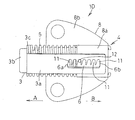
- (Fifth embodiment) 21 to 23 show a tensioner 1D according to a fifth embodiment of the present invention.
- the tensioner 1D of this embodiment is provided with a plurality of engaging recesses 11 in the guide hole 6 of the guide member 3, and the other configuration is the same as that of the first embodiment.
- the plurality of engaging recesses 11 are formed on one end surface of the long-side end surfaces of the guide hole 6, and are between the start end portion 6 a and the end end portion 6 b. Are formed so as to be continuous along the length direction of the guide hole 6.
- Each engaging recess 11 is formed in an oblique U-shape inclined with respect to the backward direction B of the propelling member 2.
- Engaging convex portions 12 are formed on the fixing bracket 8 which is a constituent member of the supporting member 4 with respect to the plurality of engaging concave portions 11 on the guide member 3 side. As shown in FIG. 23, the engaging convex portion 12 is formed so as to protrude upward from the top of the substantially arc-shaped holding portion 8a of the fixing bracket 8, and the engaging convex portion 12 of this embodiment. Has a cylindrical shape with a diameter that can be engaged with the engaging convex portion 11.
- the guide member 3 is integrated.
- the advancement of the propulsion member 2 is stopped, and a temporarily fixed state in which the retracted state of the propulsion member 2 is maintained can be obtained. Therefore, the propelling member 2 can be temporarily fixed as appropriate while the propelling member 2 is advanced. And with respect to this temporarily fixed state, the propelling member 2 can be advanced again by rotating the guide member 3 to release the engaging convex portion 12 from the engaging concave portion 11.
- Other effects are the same as those of the first embodiment.
- the plurality of engaging recesses 11 of the guide hole 6 are formed so as to be continuous along the length direction of the guide hole 6, but are formed in a state of being separated at a predetermined interval. Also good. Moreover, as the convex part 11 for engagement, it is good also as rectangular shapes other than diagonal U shape, a triangular shape, etc.
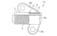
- (Sixth embodiment) 24 to 26 show a tensioner 1E according to a sixth embodiment of the present invention.
- the tensioner 1E of this embodiment is obtained by changing the tensioner 1 of the first embodiment to a ratchet type.
- the propulsion member 2 is inserted into the holding member 7 so as to move forward.
- the ratchet 23 is provided to face the end portion 2b of the propelling member 2 on the backward direction side.
- a taper portion 21 whose diameter gradually decreases rearward is formed on the end portion 2b of the propelling member 2 in the backward direction, and a plurality of ratchets 23 are provided in the holding member 7 so as to contact the taper portion 21.
- Ratchet teeth 25 are formed between each ratchet 23 and the holding member 7. The ratchet teeth 25 allow the propelling member 2 to move in the advancing direction, but are formed so that the propelling member 2 bites each other by moving in the backward direction. Thereby, the backward movement of the propelling member 2 can be stopped by the ratchet 23.
- a folded tube portion 3e is formed on the guide member 3.
- the folded tube portion 3e is folded at a position facing the end portion 2a on the advancing direction side of the propelling member 2, and the end portion on the advancing direction side of the propelling member 2 is inserted into the folded tube portion 3e and crimped.
- the guide member 3 and the propelling member 2 are coupled, and these move forward and backward together.
- the guide member 3 is located at an oblique portion in the circumferential direction of the propelling member 2, and is an engaging convex portion that is slidably inserted into the guide hole 6 of the guide member 3.
- Reference numeral 12 denotes a circumferentially inclined portion of the propelling member 2.
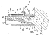
- FIG. 27 shows a tensioner 1F according to a seventh embodiment of the present invention.
- the support member 4 is formed only by the cylindrical holding member 7, and the fixing bracket 8 is omitted.
- the holding member 7 is directly attached to the inside of the engine main body 200.
- an attachment convex portion 250 is formed on the inner surface of the engine main body 200.
- a screw portion 250a is formed on the outer peripheral surface of the attachment convex portion 250, and a screw portion 7a is formed on the inner peripheral surface of the holding member 7.
- the tensioner 1F is attached to the engine body 200 by screwing them together.
- the propelling member 2 is held by a cylindrical holding member 7 and moves forward and backward in the axial direction in this holding state.
- the propulsion member 2 in this embodiment is formed in a bottomed cylindrical shape in which the end portion 2a on the advancing direction side is closed and the end portion 2b on the reverse direction side is opened, and the elastic member 5 is inserted therein. Yes.
- One end of the elastic member 5 is in contact with the end surface of the end portion 2 a on the advancing direction side of the propelling member 2, and the other end is in contact with the end surface of the mounting convex portion 250 of the engine body 200.
- the elastic member 5 has a structure in which an urging force is directly applied to the propelling member 2.
- the guide member 3 is coupled to the propelling member 2 by crimping the fixing cylinder portion 3b, so that the guide member 3 and the propelling member 2 can move forward and backward.
- the bottomed cylindrical propelling member 2 has an end 2b on the reverse direction side facing an outlet of a hydraulic circuit 260 formed in the engine body 200, and oil from the hydraulic circuit 260 is introduced into the outlet. Therefore, the tensioner 1F of this embodiment has a structure in which an axial load is applied to the propelling member 2 by both the urging force of the elastic member 5 and the oil pressure of the hydraulic circuit 260.
- a screw member 27 is attached to the tensioner 1F.
- the screw member 27 is formed by a nut 28 and a bolt 29.
- the bolt 29 of the screw member 27 passes through the guide hole 6 formed in the guide member 3 and is fixed to the holding member 7. Accordingly, when the guide member 3 moves, the bolt 29 relatively moves inside the guide hole 6.
- the guide member 3 can be stopped at an arbitrary position, and the forward / backward movement of the propelling member 2 can be locked.
- the propulsion member 2 can be moved back and forth, and the propulsion member 2 moves forward due to the elastic member 5 acting on the propulsion member 2 and the axial load caused by the oil pressure.
- Appropriate tension can be applied to 230.
- the guide hole 6 is formed in the elongate shape which the start end part 6a and the termination
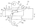
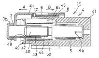
- (Eighth embodiment) 28 to 30 show a tensioner 1G according to an eighth embodiment of the present invention.
- the propelling member 2 is attached in a state of being screwed to the rotating member 40, and the propelling member 2 and the rotating member 40 are accommodated in the case 41 in a screwed state.
- the propulsion member 2 is formed by a cylindrical body extending in the axial direction
- the internal thread portion 43 is formed on the inner peripheral surface of the propulsion member 2
- the external thread portion 44 on the outer peripheral surface of the rotating member 40 is screwed to the internal thread portion 43.
- the rotating member 40 is rotationally biased by the elastic member 5 made of a torsion spring, and the propelling member 2 moves forward and backward in the axial direction with respect to the case 41 by the rotation of the rotating member 40. That is, the elastic member 5 in this embodiment indirectly applies an axial load to the propelling member 2 via the rotating member 40.
- the elastic member 5 In order to urge the rotating member 40 to rotate, the elastic member 5 has a hook portion 45 on one end side locked to the case 41 and a hook portion 46 on the other end side inserted into the rotating member 40 and locked.
- the case 41 functions as the holding member 7 that accommodates the propelling member 2 so as to be movable forward and backward.
- the case 41 is held by the holding portion 8 a of the fixing bracket 8, and the support member 4 of this embodiment is formed by the case 41 and the fixing bracket 8.
- the fixing bracket 8 has a pair of fixing portions 8b attached to the engine body 200 integrally formed on both sides of the holding portion 8a.
- the propulsion member 2 is rotationally restricted by a bearing 47 attached to the tip portion of the case 41, and the propelling member 2 advances from the case 41 by rotating the rotating member 40 in this rotationally restricted state. Etc. are pressed.
- the bearing 47 is fixed to the tip portion of the case 41 by a press ring 49.
- the bearing 47 is formed with a non-circular sliding hole 48 such as an oval shape or a parallel cut, and the propelling member 2 having the same non-circular outer shape penetrates the sliding hole 48 so that the propelling member 2 is It is constrained to rotate and moves linearly back and forth in the axial direction.
- a cylindrical spacer 50 is disposed outside the rotating member 40.
- the spacer 50 has a front end faced to the bearing 47, and when the spacer 50 abuts the bearing 47, the advancement of the propulsion member 2 is prevented and the dropout of the propulsion member 2 from the case 41 is prevented.
- the guide member 3 is attached to the propelling member 2.
- the guide member 3 is a plate-shaped guide main body portion 3a extending in the same direction as the axial direction of the propelling member 2, and a bottomed fixing cylinder integrally formed on the guide main body portion 3a on the advancing direction A side of the propelling member 2. It is formed by the part 3b. And the guide member 3 can be united with the propulsion member 2 and propelled by inserting the tip of the propulsion member 2 into the fixing cylinder portion 3b.
- the guide member 3 is rotatable with respect to the propelling member 3 in the clockwise and counterclockwise directions indicated by arrows C and D.
- a guide hole 6 and an engagement recess 11 are formed, and an engagement protrusion 12 corresponding to the guide hole 6 and the engagement recess 11 is formed in the fixing bracket 8.
- the guide hole 6 is formed in the guide main body 3a of the guide member 3 so as to extend along the axial direction of the propelling member 2.
- the guide hole 6 is a closed space in which both end portions 6a and 6b in the length direction are closed.
- the engaging recess 11 is formed at the end of the propelling member 2 on the advancing direction A side (starting end 6a of the guide hole 6) so as to extend in a direction orthogonal to the length direction of the guide hole 6.
- the engaging convex portion 12 is formed so as to protrude upward from the top portion of the holding portion 8 a in the fixing bracket 8, and can be engaged with and disengaged from the engaging concave portion 11. Further, the engaging convex portion 12 is located inside the guide hole 6, and the guide member 3 is slidable relative to the engaging convex portion 12.
- the engaging convex portion 12 is engaged with the engaging concave portion 11, and the forward and backward movement of the propelling member 2 is locked. Can be installed.
- the guide projection 3 is rotated in the direction of the arrow D, whereby the engagement projection 12 is disengaged from the engagement recess 11. Since the engaging convex portion 12 enters the guide hole 6, the forward and backward movement of the propelling member 2 is allowed.
- the propulsion member 2 advances by the spring force of the elastic member 5, presses the chain guide 240, and applies an appropriate tension to the timing chain 230.
- the propulsion member 2 is temporarily moved with respect to the case 41 by the guide hole 6 of the guide member 3, the engaging concave portion 11 provided in the guide hole 6, and the engaging convex portion 12 provided in the fixing bracket 8. Fixing and prevention of falling off can be performed. For this reason, the number of parts is small, the structure is simple and the assembly is easy, and it is not necessary to discard the parts for temporarily fixing the propelling member 2, so that waste can be eliminated.
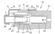
- FIG. 31 shows a tensioner 1H according to a modification of this embodiment.
- the tensioner 1H is a unit in which the case 41 and the fixing bracket 8 in the tensioner 1G shown in FIGS. 28 to 30 are integrated.
- Reference numeral 51 denotes a case member integrated with the fixing bracket.
- the case member 51 is formed with an engaging convex portion 12, and the engaging convex portion 12 is inserted into the guide hole 6 of the guide member 3 and is freely detachable from the engaging concave portion 11 on the guide hole 6 side. Yes. With such a structure, the number of parts can be further reduced, and assembly is facilitated. Other effects are the same as those of the tensioner 1G shown in FIGS.
- the present invention is not limited to the above embodiment, and various modifications can be made.
- a compression coil spring is used as the elastic member 5
- a spring or a disc spring can be used.
Landscapes
- Engineering & Computer Science (AREA)
- General Engineering & Computer Science (AREA)
- Mechanical Engineering (AREA)
- Devices For Conveying Motion By Means Of Endless Flexible Members (AREA)
Priority Applications (1)
| Application Number | Priority Date | Filing Date | Title |
|---|---|---|---|
| JP2014518689A JP6175057B2 (ja) | 2012-05-30 | 2013-05-28 | テンショナー |
Applications Claiming Priority (2)
| Application Number | Priority Date | Filing Date | Title |
|---|---|---|---|
| JP2012123018 | 2012-05-30 | ||
| JP2012-123018 | 2012-05-30 |
Publications (1)
| Publication Number | Publication Date |
|---|---|
| WO2013180145A1 true WO2013180145A1 (fr) | 2013-12-05 |
Family
ID=49673335
Family Applications (1)
| Application Number | Title | Priority Date | Filing Date |
|---|---|---|---|
| PCT/JP2013/064812 Ceased WO2013180145A1 (fr) | 2012-05-30 | 2013-05-28 | Tendeur |
Country Status (2)
| Country | Link |
|---|---|
| JP (1) | JP6175057B2 (fr) |
| WO (1) | WO2013180145A1 (fr) |
Cited By (4)
| Publication number | Priority date | Publication date | Assignee | Title |
|---|---|---|---|---|
| DE102014203947A1 (de) * | 2014-03-05 | 2015-09-10 | Schaeffler Technologies AG & Co. KG | Schraubtriebspanner aus Blech |
| WO2016021567A1 (fr) * | 2014-08-08 | 2016-02-11 | 日本発條株式会社 | Dispositif d'application de charge |
| JPWO2016021740A1 (ja) * | 2014-08-08 | 2017-06-01 | 日本発條株式会社 | テンショナ |
| CN109210159A (zh) * | 2017-07-07 | 2019-01-15 | 株式会社椿本链条 | 张紧装置 |
Citations (4)
| Publication number | Priority date | Publication date | Assignee | Title |
|---|---|---|---|---|
| JPH08145130A (ja) * | 1994-11-25 | 1996-06-04 | Toyota Motor Corp | テンショナ |
| JPH0953692A (ja) * | 1995-08-11 | 1997-02-25 | Borg Warner Automot Kk | 油圧テンショナ |
| JPH09303503A (ja) * | 1996-05-10 | 1997-11-25 | Borg Warner Automot Kk | 油圧テンショナ |
| JP2011021643A (ja) * | 2009-07-14 | 2011-02-03 | Ntn Corp | チェーンテンショナ |
Family Cites Families (1)
| Publication number | Priority date | Publication date | Assignee | Title |
|---|---|---|---|---|
| JP3329609B2 (ja) * | 1994-12-28 | 2002-09-30 | ボーグ・ワーナー・オートモーティブ株式会社 | テンショナ |
-
2013
- 2013-05-28 WO PCT/JP2013/064812 patent/WO2013180145A1/fr not_active Ceased
- 2013-05-28 JP JP2014518689A patent/JP6175057B2/ja active Active
Patent Citations (4)
| Publication number | Priority date | Publication date | Assignee | Title |
|---|---|---|---|---|
| JPH08145130A (ja) * | 1994-11-25 | 1996-06-04 | Toyota Motor Corp | テンショナ |
| JPH0953692A (ja) * | 1995-08-11 | 1997-02-25 | Borg Warner Automot Kk | 油圧テンショナ |
| JPH09303503A (ja) * | 1996-05-10 | 1997-11-25 | Borg Warner Automot Kk | 油圧テンショナ |
| JP2011021643A (ja) * | 2009-07-14 | 2011-02-03 | Ntn Corp | チェーンテンショナ |
Cited By (8)
| Publication number | Priority date | Publication date | Assignee | Title |
|---|---|---|---|---|
| DE102014203947A1 (de) * | 2014-03-05 | 2015-09-10 | Schaeffler Technologies AG & Co. KG | Schraubtriebspanner aus Blech |
| WO2016021567A1 (fr) * | 2014-08-08 | 2016-02-11 | 日本発條株式会社 | Dispositif d'application de charge |
| JPWO2016021740A1 (ja) * | 2014-08-08 | 2017-06-01 | 日本発條株式会社 | テンショナ |
| CN109210159A (zh) * | 2017-07-07 | 2019-01-15 | 株式会社椿本链条 | 张紧装置 |
| KR20190005756A (ko) * | 2017-07-07 | 2019-01-16 | 가부시기가이샤쯔바기모도체인 | 텐셔너 |
| US10767739B2 (en) | 2017-07-07 | 2020-09-08 | Tsubakimoto Chain Co. | Tensioner |
| KR102156056B1 (ko) * | 2017-07-07 | 2020-09-15 | 가부시기가이샤쯔바기모도체인 | 텐셔너 |
| CN109210159B (zh) * | 2017-07-07 | 2021-07-30 | 株式会社椿本链条 | 张紧装置 |
Also Published As
| Publication number | Publication date |
|---|---|
| JPWO2013180145A1 (ja) | 2016-01-21 |
| JP6175057B2 (ja) | 2017-08-02 |
Similar Documents
| Publication | Publication Date | Title |
|---|---|---|
| DE69912558T2 (de) | Hydraulische Spannvorrichtung mit externem Klinkenwerk | |
| JP6175057B2 (ja) | テンショナー | |
| JP4938102B2 (ja) | チェーンテンショナ | |
| CN102171487B (zh) | 张紧器 | |
| JP5266286B2 (ja) | 制限システムを備えた張力付与装置 | |
| US6547684B2 (en) | Ratchet tensioner with plunger releasing mechanism | |
| KR20030057393A (ko) | 래치트 기구를 구비한 유압식 장력기 | |
| JPS63500467A (ja) | 自己展張式ベルト展張装置 | |
| US8419575B2 (en) | Ball-type tensioner | |
| US20150063939A1 (en) | Self-Locking Screwing Attachment Device And Assembly Provided With Same | |
| JP4416769B2 (ja) | チェーンテンショナ | |
| US9046153B2 (en) | Ratchet tensioner | |
| JP3538662B2 (ja) | 推進力付与装置 | |
| RU104268U1 (ru) | Натяжитель цепи двигателя автомобиля | |
| JP3883191B2 (ja) | ラチェット式テンショナのプランジャ制止具 | |
| JP6818025B2 (ja) | テンショナ | |
| KR100491373B1 (ko) | 래칫식 텐셔너의 수지제 플런저 제지기구 | |
| JP2008223790A (ja) | テンショナー | |
| US20050215370A1 (en) | Hydraulic tensioner | |
| JP6867383B2 (ja) | テンショナ | |
| WO2010038619A1 (fr) | Tendeur | |
| JP2006305679A (ja) | ねじ締付工具用仮締装置 | |
| JP4680160B2 (ja) | テンショナリフタ | |
| JP4917789B2 (ja) | オートテンショナ | |
| JP4927376B2 (ja) | オートテンショナ |
Legal Events
| Date | Code | Title | Description |
|---|---|---|---|
| 121 | Ep: the epo has been informed by wipo that ep was designated in this application |
Ref document number: 13796477 Country of ref document: EP Kind code of ref document: A1 |
|
| ENP | Entry into the national phase |
Ref document number: 2014518689 Country of ref document: JP Kind code of ref document: A |
|
| NENP | Non-entry into the national phase |
Ref country code: DE |
|
| 122 | Ep: pct application non-entry in european phase |
Ref document number: 13796477 Country of ref document: EP Kind code of ref document: A1 |