WO2013183147A1 - Dispositif de téléphone sous l'eau - Google Patents
Dispositif de téléphone sous l'eau Download PDFInfo
- Publication number
- WO2013183147A1 WO2013183147A1 PCT/JP2012/064698 JP2012064698W WO2013183147A1 WO 2013183147 A1 WO2013183147 A1 WO 2013183147A1 JP 2012064698 W JP2012064698 W JP 2012064698W WO 2013183147 A1 WO2013183147 A1 WO 2013183147A1
- Authority
- WO
- WIPO (PCT)
- Prior art keywords
- underwater
- microphone
- diver
- communication device
- bone
- Prior art date
- Legal status (The legal status is an assumption and is not a legal conclusion. Google has not performed a legal analysis and makes no representation as to the accuracy of the status listed.)
- Ceased
Links
Images











Classifications
-
- B—PERFORMING OPERATIONS; TRANSPORTING
- B63—SHIPS OR OTHER WATERBORNE VESSELS; RELATED EQUIPMENT
- B63C—LAUNCHING, HAULING-OUT, OR DRY-DOCKING OF VESSELS; LIFE-SAVING IN WATER; EQUIPMENT FOR DWELLING OR WORKING UNDER WATER; MEANS FOR SALVAGING OR SEARCHING FOR UNDERWATER OBJECTS
- B63C11/00—Equipment for dwelling or working underwater; Means for searching for underwater objects
- B63C11/02—Divers' equipment
- B63C11/26—Communication means, e.g. means for signalling the presence of divers
Definitions
- the present invention relates to an underwater communication device.
- An underwater communication device that is used by a diver to have a conversation underwater is known (for example, see Patent Document 1).
- Some underwater communication devices have a structure in which a mouth such as a full face mask or a half mask is used to cover the mouth and the nose, mouth and lips can be moved freely. If this kind of underwater communication device is used, it is possible to make a call in the same way as on land.
- the mask that covers the mouth and the like has a structure that cannot be easily detached and is difficult to handle.
- this type of underwater communication device is used for divers who need to speak underwater for business purposes, such as military, firefighting, and underwater reporters, and is not used for recreational divers.
- a microphone and a speaker are generally connected to the main body with a cable.
- the cable is entangled with the hose around the diver and the string for fixing the equipment, and handling is complicated.
- the microphone and speaker it is also possible to fix the microphone and speaker to the main unit so that the cable is not exposed to the outside.
- the vibration of the speaker is diffused throughout the underwater communication device, and the vibration cannot be efficiently transmitted to the diver as sound.
- vibration caused by diver's breathing or the like vibrates the underwater communication device, and this vibration is transmitted to the microphone and mixed into the microphone output as noise.
- the present invention has been made in view of the above circumstances, and an object of the present invention is to provide an underwater call device that enables high-quality voice calls while wearing diving equipment.
- an underwater communication device includes: A microphone that converts the diver's audio signal into an electrical signal; A transmitter for transmitting an electrical signal output from the microphone to the outside; With the microphone in contact with the diver, a mounting part to be mounted on the diver; With The microphone is mounted apart from the mounting portion via an elastic body. It is characterized by that.
- an underwater communication device provides: A receiver for receiving audio data transmitted from the outside; A bone-conducting speaker that outputs vibration corresponding to the audio data received by the receiver; With the bone conduction speaker in contact with the diver, a mounting part to be mounted on the diver, With The bone-conducting speaker is mounted apart from the mounting portion via an elastic body. It is characterized by that.
- an underwater communication device that enables a high-quality sound call while wearing diving equipment.
- the underwater communication device 100 is a device that demodulates an ultrasonic wave received from an external device into an audio signal and transmits it to a diver via a bone-conducting speaker.
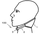
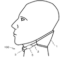
- the underwater communication device 100 has an external configuration shown in FIGS. 1A and 1B, and is attached to a diver as shown in FIG. 1C.
- the underwater communication device 100 includes a main body unit 1, a band unit 2, and a connecting unit 3.
- the main body 1 is composed of a cushion 4 and a voice interface 10, and the voice interface 10 is built in the cushion 4.
- the cushion 4 is made of a flexible material (such as chloroprene rubber) having water repellency and an anti-vibration effect. As shown in FIGS. 1A and 1B, a protrusion 11 (described later) is inserted into a portion of the cushion 4 that comes into contact with the back of the diver (including the back of the base of the neck and the vicinity of the tibia) when the main body 1 is mounted. The opening 4a to be formed is formed.
- the voice interface 10 has a resin casing, and as shown in FIG. 2, a protrusion 11 is formed on one surface of the casing. A hole 14 is formed in the protruding portion 11, and the bone conduction speaker 12 is incorporated in the hole 14.
- the bone-conducting speaker 12 is exposed on the surface of the main body 1 and contacts the back of the diver with the underwater communication device 100 attached to the diver. Thereby, the vibration emitted from the bone-conducting speaker 12 is transmitted to the diver's ear (cochlea) via the diver's bone and recognized as sound.
- the audio interface 10 demodulates and amplifies a signal from the receiving unit 17a described later.
- the voice interface 10 houses a battery 10a to be supplied to the underwater communication device 100, a charging terminal, wiring, a demodulation circuit, an amplification electronic circuit, and the like in a casing, and these are modularized. A specific structure for attaching the bone-conducting speaker 12 to the audio interface 10 will be described later.
- the battery 10a is composed of a storage battery, and is charged by being supplied with electric power from an external power source via a charging terminal. Therefore, it is not necessary to replace the battery 10a, and it is not necessary to provide a battery cover necessary for the replacement on the audio interface 10. For this reason, the gap between the battery cover and the audio interface 10 formed when the battery cover is installed is not formed, and the audio interface 10 can be configured to be watertight. Therefore, there is no possibility that water will enter the voice interface 10 by replacing the battery while the diver is wet.
- a gap is provided inside the voice interface 10.
- the voice interface 10 is watertight, it is not necessary to fill the voice interface 10 with a filler (resin or the like) for preventing water from entering the voice interface 10. Accordingly, manufacturers, divers, and the like of the underwater communication device 100 can easily disassemble the underwater communication device 100 and perform maintenance and repair.
- the receiving unit 17a is arranged on the outer surface of the main body unit 1 (the back surface of the audio interface 10, the position of the opening 4a).
- the receiving unit 17a is converted into an electrical signal.
- the data is converted and output to a demodulation circuit in the audio interface 10.
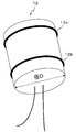
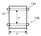
- the bone-conducting speaker 12 has a cylindrical outer shape with a diameter D as shown in FIG. Further, a power line and a signal line are drawn out from one end thereof. The bone conduction speaker 12 is connected to the receiving unit 17a through these lines.
- an O-ring 12a is arranged at a position away from one end of the bone-conducting speaker 12 by a predetermined distance, and an O-ring 12b is arranged at a position away from the other end by a predetermined distance.
- the O-rings 12a and 12b are formed from an elastic body such as resin.
- the O-rings 12 a and 12 b are formed so that the outer diameter is slightly larger than the inner diameter of the hole 14.
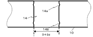
- the hole 14 has a diameter that is 2d larger than the diameter D of the bone-conducting speaker 12, for example, about 3 mm to 20 mm. Further, grooves 14 a and 14 b that engage with the O-ring are formed on the inner surface of the hole 14.
- the bone conduction speaker 12 is inserted into the hole 14 in a state where the O-rings 12a and 12b are compressed between the inner walls of the grooves 14a and 14b and the outer periphery of the bone conduction speaker 12. Due to the restoring force of the O-rings 12a and 12b, surface pressure is generated on the inner wall of the hole 14, the bone conduction speaker 12 is held in the hole 14, and the thickness between the inner wall of the hole 14 and the bone conduction speaker 12 is increased. A gap d is formed.
- an airtight space 16 is formed by the O-rings 12a and 12b, the outer surface of the bone-conducting speaker 12, and the inner surface of the hole 14.
- the airtightness of the space 16 is set to a waterproof performance equal to or higher than the diver's diving depth.
- the band portion 2 is composed of two bands made of an elastic body, and each band is connected to both ends of the main body portion 1. The other end of each band is connected to the connecting portion 3.
- the connecting portions 3 are paired and can be separated.
- the underwater communication device 100 is attached to the neck of the diver by connecting the connecting unit 3.
- the underwater communication device 100 is in close contact with the neck of the diver by the elastic force of the band unit 2.
- the diver wears the underwater communication device 100 as shown in FIG. 1C when diving.
- the receiving unit 17 a receives this, converts it into an electric signal, and supplies it to a demodulation circuit in the audio interface 10.
- the demodulation circuit demodulates the audio signal and transmits the audio signal to the bone conduction speaker 12.
- the bone conduction speaker 12 vibrates according to the received audio signal.
- the vibration emitted from the bone conduction speaker 12 is transmitted to the diver's ear (cochlea) via the diver's tibia and recognized as sound.
- the receiving unit 17a has received an ultrasonic wave including audio data.
- the received ultrasonic wave is converted into an electric signal, which is converted into an electric signal and output to a demodulation circuit in the audio interface 10.
- the electrical signal is demodulated by the demodulation circuit and output to the bone conduction speaker 12, and the bone conduction speaker 12 vibrates.
- the vibration of the bone conduction speaker 12 is attenuated by the space 16 and the O-rings 12a and 12b, and the housing of the audio interface 10 hardly vibrates. For this reason, as will be described later in Embodiment 2 and the like, even when a device (such as a microphone or gyroscope) that detects vibration is incorporated in the audio interface 10, the vibration of the bone-conducting speaker 12 propagates to the aforementioned device. And the aforementioned device does not detect the vibration of the bone-conducting speaker 12.
- a device such as a microphone or gyroscope
- the case of the bone conduction speaker 12 has a cylindrical shape and is made of a single material. For this reason, the rigidity of the case of the bone conduction speaker 12 is single, and the distortion of the vibration propagated from the vibration source disposed at the center of the case of the bone conduction speaker 12 to the diver is small. Therefore, the frequency characteristic of the bone-conducting speaker 12 is flat, and a diver can make a high-quality call using the underwater call device 100.
- the main body 1 and the like are wound around the neck, the main body 1 and the like do not block the diver's mouth and the periphery of the eyes. For this reason, it is possible to wear the underwater communication device 100 even when a diving equipment such as an underwater mask or a regulator is worn.
- the bone conduction speaker 12 is covered with the diver and the main body 1. For this reason, the bone conduction speaker 12 does not receive a physical stimulus from the outside and does not fall off. Furthermore, since the space 16 has a certain waterproof performance, even if a diver dives, the air layer between the bone conduction speaker 12 and the audio interface 10 is not lost, and the vibration of the bone conduction speaker 12 is not lost. Does not propagate to the audio interface 10.
- the bone conduction speaker 12 is fixed to the audio interface 10 through a plurality of O-rings. For this reason, it is possible to remove the bone-conducting speaker 12 from the audio interface 10, and replacement and repair are easy.
- the bone interface speaker 12, the receiving unit 17a, the battery, the wiring, the electronic circuit, and the like can be housed in the audio interface 10 and modularized.
- the bone-conducting speaker 12 is held by the two O-rings 12a and 12b, but may be held by three or more O-rings in order to improve stability.
- an O-ring is used as an example of means for holding the bone-conducting speaker 12 away from the housing of the audio interface 10
- specific means are arbitrary.
- another elastic ring such as a C-ring can be used instead of the O-ring, and even if the gap between the bone-conducting speaker 12 and the audio interface 10 is sealed with an elastic gasket, the vibration from the bone-conducting speaker 12 can be transmitted to the audio interface. It is possible to obtain a similar effect of not propagating to 10 cases.
- the wiring connected to the bone-conducting speaker 12 may be covered with a flexible member. In this way, vibration transmitted from the bone conduction speaker 12 to the wiring can be reduced.
- the space 16 may be filled with a vibration isolating material (chloroprene rubber or the like). In this way, it is possible to further suppress vibration from the bone-conducting speaker 12 to the housing of the audio interface 10.
- a vibration isolating material chloroprene rubber or the like.
- the reception-only underwater telephone (receiving) apparatus 100 including the receiving unit 17a and the bone conduction speaker 12 has been described.
- the present invention is a bidirectional underwater telephone apparatus including a microphone in addition to the speaker. 200 is also applicable.
- the bidirectional underwater communication device 200 will be described.
- the external configuration of the underwater communication device 200 according to the present embodiment is substantially the same as that shown in FIGS. 1A and 1B, but is different from the underwater communication device 100 in that the microphone 13 is provided.
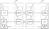
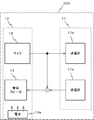
- the bone interface speaker 12 and the microphone 13 are mounted side by side on the audio interface 10 as shown in FIG.
- the microphone 13 is composed of a bone-conduction microphone including a piezoelectric element and the like, has a cylindrical shape like the bone-conduction speaker 12 shown in FIG. 3, and two O-rings are mounted on the outer periphery thereof.
- the voice interface 10 has a hole 15 for accommodating the microphone 13. Similarly to the hole 14, the hole 15 has a groove corresponding to the O-ring.
- the microphone 13 is attached in such a form that an O-ring is held in a groove in the hole 15.
- An airtight space filled with air is formed between the microphone 13 and the inner surface of the hole 15.
- the microphone 13 senses the diver's vocal cord vibration through, for example, the tibia, and converts the vibration into an electrical signal (audio signal) including audio data and outputs the electric signal.
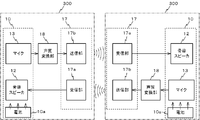
- the main body 1 further includes a transmission unit 17b in addition to the reception unit 17a.
- the receiving unit 17a and the transmitting unit 17b are accommodated in a transmitting / receiving unit 17 including a transmitting circuit, a transmitting antenna, and the like.
- the transmission circuit modulates the audio signal output from the microphone 13.
- the transmission antenna converts the modulated audio signal into an ultrasonic wave and outputs it to the outside.
- each diver wears the underwater communication device 200. As shown in FIG. 7, when any diver speaks, the vibration is transmitted through the bone to vibrate the tibia. This vibration is picked up by the bone-conduction microphone 13, converted into an electrical signal, and supplied to the transmitter 17b.
- the transmission unit 17b modulates the received electrical signal, converts the modulated signal into an ultrasonic wave, and outputs it into water.
- the ultrasonic wave propagated in water is received by the receiving unit 17a of another diver, converted into an electric signal, demodulated, and supplied to the bone-conducting speaker 12.
- the bone conduction speaker 12 transmits the vibration to the diver's tibia. The vibration is transmitted to the diver's ear via the tibia and recognized as sound.
- voice data is transmitted / received by ultrasonic waves between the underwater communication devices 200, so that divers can communicate with each other underwater.
- the vibration of the bone conduction speaker 12 is attenuated by the difference in acoustic impedance between the air in the gap 7 around the bone conduction speaker 12 and the air in the gap around the microphone 13.
- external vibration propagating through the main body 1 is also attenuated by the air in the gap around the microphone 13. For this reason, the microphone 13 can acquire clear sound.
- vibration to the microphone 13 can be further suppressed, and the microphone 13 can acquire a clear sound.
- the microphone 13 is not affected by external noise (vibration and exhaust sound), and can obtain a clear sound quality and flat characteristics. Therefore, for example, when a tour customer and a tour guide wear the underwater communication device 200, the tour guide can transmit a clear instruction to the tour customer even in the water, and confirms a response from the tour customer. be able to.
- the underwater communication device 200 according to the second embodiment is used in a state of being wound around a diver's neck. Therefore, it can be worn even with leisure diving equipment such as underwater masks and regulators.
- the receiving unit 17a, the bone conduction speaker 12, the transmitting unit 17b, and the microphone 13 are integrally attached to the main body unit 1. For this reason, the whole apparatus can be formed compactly so that it does not get in the way even if a diver is attached.
- the microphone 13 may be a throat microphone, for example.
- the microphone 13 is disposed not in the audio interface 10 but in the small casing 5 as shown in FIG.
- the small casing 5 is arranged via the band unit 2 so as to be positioned near the throat when the underwater communication device 200 is mounted.
- the small housing 5 has a microphone mounting hole having the structure illustrated in FIG. 4B, and a throat microphone is mounted in this hole as illustrated in FIG. 4C.
- the voice of the diver sensed by the microphone 13 is transmitted only to the transmission unit 17b.
- the voice of the diver sensed by the microphone 13 is transmitted only to the transmission unit 17b.
- it is transmitted to the transmission unit 17b and also transmitted to the bone conduction speaker 12. May be.
- the voice of the diver input to the microphone 13 is also transmitted to the diver himself via the bone conduction speaker 12.
- Divers can check their voices in real time and understand how clearly the other party is listening to the voices.
- the diver can appropriately provide a clear sound quality to the other party by adjusting the position of the microphone 13 in contact with the diver.
- the receiving unit 17a, the bone conduction speaker 12, the transmitting unit 17b, and the microphone 13 are all arranged in the main body 1.
- the receiving unit 17a, At least one of the bone-conducting speaker 12, the transmission unit 17b, and the microphone 13 may be used in a state where it is detached from the main body unit 1 (separated from the main body unit 1).
- the portion separated from the main body 1 is connected to a corresponding portion in the main body 1 (bone conduction speaker 12 and receiving portion 17a or microphone 13 and transmitting portion 17b) with a cable (not shown) for transmitting an audio signal. Will be.
- the degree of freedom of the mounting position of the receiving unit 17a, the bone-conducting speaker 12, the transmitting unit 17b, and the microphone 13 can be increased.
- the main body 1 can be attached to the neck of a diver, and the bone conduction speaker 12 and the microphone 13 can be attached to the mask strap. Further, if each part can be separated, the maintenance of the apparatus becomes easy.
- voice can be transmitted and received at the same time, and full-duplex communication is realized.
- full-duplex communication may be used.
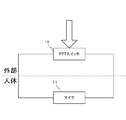
- a PTT (Push To Talk) switch may be used so that only voice transmission is possible when pressed and only voice reception is possible when released.
- PTT switch When such a PTT switch is pressed, the connection between the receiving unit 17a and the bone conduction speaker 12 is cut off, the transmission unit 17b and the microphone 13 are connected, and when released, the receiving unit 17a and the bone conduction speaker 12 are connected. This is realized by connecting the speaker 12 and assembling a circuit so as to disconnect the connection between the transmitter 17b and the microphone 13.
- a PTT switch 19 When a PTT switch is used, a PTT switch 19 may be arranged on the same axis as the microphone 13 as shown in FIG. With such an arrangement, when the diver presses the PTT switch 19, the microphone 13 arranged below the PTT switch 19 is in close contact with the body of the diver. For this reason, the microphone 13 can stably pick up the voice of the diver.
- the diver is not switched to the transmission mode unless the PTT switch 19 is pressed, and there is no possibility that the diver unintentionally transmits his / her voice.
- a switch may be used that transmits when it is tilted to the transmitting side and receives when it is tilted to the receiving side.
- the diver does not need to keep pressing the PTT switch 19 when it is desired to always transmit voice, so that the convenience of the underwater communication device 200 is improved.
- the bone-conducting speaker 12 is a component dedicated to voice output
- the microphone 13 is a component dedicated to voice input.
- the voice input / output function may be realized by a single component. . That is, the bone conduction speaker 12 may be used as the microphone 13, and the microphone 13 may be used as the bone conduction speaker 12. According to such a configuration, since the number of components installed in the underwater telephone device 200 is reduced, the underwater telephone device 200 can be downsized.
- the underwater communication device 200 according to the second embodiment is advantageous in terms of cost because it has a simpler configuration than those according to the following embodiments.
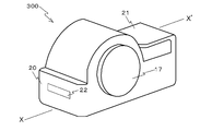
- the underwater communication device 300 according to the third embodiment is substantially the same as the underwater communication devices 100 and 200 according to the first and second embodiments described above, except that the internal circuit configuration includes an external interface 22 described later. Although it is the same, it differs from the underwater communication devices 100 and 200 according to Embodiments 1 and 2 in the appearance and the diver mounting method.
- the underwater communication device 300 includes a housing 20, a hook 21, a transmission / reception unit 17, an external interface 22, a diaphragm 23, a bone conduction speaker 12, and a microphone 13.
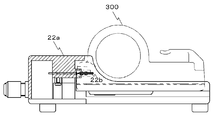
- FIG. 11B is an X-X ′ sectional view in FIG. 11A.
- the housing 20 is composed of a watertight member, and a hook 21 is installed at one end in the short direction and an external interface 22 is installed at the other end.
- a cylindrical transmission / reception unit 17 is installed on the top surface of the housing 20, and a diaphragm 23, a bone conduction speaker 12, a microphone 13, a bone conduction speaker 12 and a microphone 13 are provided on the bottom surface of the housing 20. Two openings are provided for storing the.
- the external interface 22 is an interface to which a dedicated connector (for example, for USB (Universal Serial Bus) cable, mini USB cable, etc.) is connected, and the underwater communication device 300 transmits and receives data to and from an external device via the external interface 22. It can be charged.
- a dedicated connector for example, for USB (Universal Serial Bus) cable, mini USB cable, etc.
- the diaphragm 23 is fixed in close contact with the housing 20.
- the diaphragm 23 has an opening at a position where the housing 20 engages with the opening in which the microphone 13 is accommodated.
- the microphone 13 penetrates through the opening of the diaphragm 23 and is exposed to the outside, and is disposed in the housing 20 via an O-ring in the same manner as the underwater communication device 200 in the second embodiment.
- the bone-conducting speaker 12 is not exposed to the outside, and is fixed to the diaphragm 23 with screws as shown in the figure.
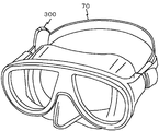
- the underwater communication device 300 As shown in FIG. 13, the underwater communication device 300 according to the third embodiment is attached to a mask strap 70 used by a diver.
- the underwater communication device 300 is attached such that the mask strap 70 is passed between the hook 21 and the housing 20 (the mask strap 70 is sandwiched), and the mask strap 70 and the head of the diver are interposed between the underwater communication device 300. ing.
- the vibration generated by the bone conduction speaker 12 propagates to the entire surface in contact with the head of the diver, that is, the diaphragm 23 and is transmitted to the head of the diver.
- the underwater communication device 300 can transmit all sound vibrations emitted from the bone-conducting speaker 12 to the diver.
- the microphone 13 since the microphone 13 is installed in the housing 20 via the O-rings 12a and 12b as in the second embodiment, it is not affected by external noise.
- the underwater communication device 300 is fastened to the mask strap 70, so that the bone conduction speaker 12 (diaphragm 23) and the microphone 13 are in close contact with the head of the diver, and the bone conduction is performed.
- the sound vibration emitted from the speaker 12 can be efficiently transmitted to the diver, and the sound emitted from the diver can be efficiently transmitted to the microphone 13.
- a diver can make a high-quality call using the underwater call device 300.
- the dedicated connector of the external interface 22 of the underwater communication device 300 may be, for example, a contact probe.
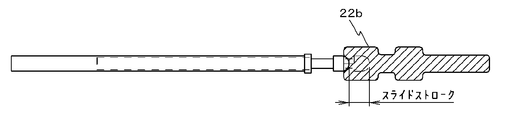
- the external interface 22 has an external connection having terminals including spring pins, contact probes, and the like. It is possible to connect to the device 22a, and the underwater communication device 300 can transmit / receive data to / from the external connection device 22a, charge, etc. via the contact probe and the dedicated terminal 22b.
- the dedicated terminal 22b of the external interface 22 can supply power even when wet, it is not necessary to install a lid on the external interface 22. Therefore, the user does not need to open and close the lid, and the underwater communication device 300 can be easily connected to an external device.
- an O-ring 22c may be provided in the groove portion of the dedicated terminal 22b.
- the underwater communication device 300 can be configured to be more watertight.
- a plurality of O-rings 22c may be provided in the groove portion of the dedicated terminal 22b. According to such a configuration, the dedicated terminal 22b is stably held by the underwater communication device 300.
- the bone conduction speaker 12 is fixed to the diaphragm 23 with screws, but the fixing method itself is arbitrary.
- an adhesive may be applied to the bone conduction speaker and fixed to the diaphragm 23.
- the overall configuration of the underwater communication device 400 according to Embodiment 4 is substantially the same as that shown in FIGS. 1A and 1B.
- the underwater call device 400 according to the fourth embodiment is different in the internal circuit configuration from the underwater call devices 100, 200, and 300 according to the first, second, and third embodiments.
- the underwater communication device 400 according to the fourth embodiment is different from the first, second, and third embodiments in that a voice quality conversion unit 18 is further provided.
- the voice quality conversion unit 18 inputs the voice signal output from the microphone 13.
- the voice quality conversion unit 18 performs, for example, phoneme analysis processing and voice recognition processing, converts voice based on the input voice signal into clearer voice, and sends a voice signal corresponding to the converted voice to the transmission unit 17b. Output.
- the voice quality conversion unit 18 may convert the indistinct speech into the clear speech in units of phonemes, or may recognize the indistinct speech and convert it into the clear artificial speech. In this case, voice quality conversion may be performed using a database that links unclear sound data and clear sound data.
- cepstrum and LPC Linear Predictive Coding
- HMM Hidden Markov Model
- the underwater communication device 400 since the voice that is unclear in the water is transmitted as ultrasonic waves as clear, the clear conversation even in the water. Is possible.
- the receiving unit 17a, the bone conduction speaker 12, the transmitting unit 17b, the microphone 13, and the voice quality converting unit 18 are integrally attached to the main body unit 1. In this way, the entire apparatus can be designed to be compact so that it does not get in the way even if a diver is attached.
- the receiving unit 17a, the bone-conducting speaker 12, the transmitting unit 17b, the microphone 13, and the voice quality conversion unit 18 is detached from the main body 1 and separated (from the main body 1). And may be made available.
- the portion separated from the main body 1 is connected to a corresponding portion in the main body 1 (bone conduction speaker 12 and receiving portion 17a or microphone 13 and transmitting portion 17b) with a cable (not shown) for transmitting an audio signal. Will be.
- the degree of freedom of the mounting positions of the receiving unit 17a, the bone conduction speaker 12, the transmitting unit 17b, and the microphone 13 can be increased.
- the underwater communication device 100, 200, 400 is of a type that is wound around the neck of a diver.
- the present invention is not limited to this.
- the underwater communication devices 100, 200, and 400 may be attached to a diving suit 50, a diving hood 60, and a diving mask strap 70 that a diver wears. .
- the bone conduction speaker 12 and the microphone 13 come into contact with the body of the diver through the diving suit 50 or the like.
- the output of the bone conduction speaker 12 is absorbed by the diving suit 50 and the like, and only a part is transmitted to the diver.
- the output of the diver to the microphone 13 is absorbed by the diving suit 50 and the like, and only a part is transmitted to the microphone 13.
- the amplification factor of the amplification electronic circuit in the voice interface 10 is set to a value that can obtain a volume suitable for a call. With this setting, even if the output of the bone conduction speaker 12 and the input to the microphone 13 are absorbed by the diving suit 50 or the like, the diver can talk clearly.
- the transmission / reception unit 17 is not exposed to the outside and is covered with the diving suit 50 or the like. At this time, it becomes difficult for the transmitter / receiver 17 to transmit / receive ultrasonic waves. In this case, an opening may be provided in the diving suit 50 or the like so that the transmission / reception unit 17 is exposed.
- the main body 1 and the transmission / reception unit 17 may be connected by a waterproof flexible cable or the like so that the transmission / reception unit 17 is exposed to the outside.
- the transmission / reception unit 17 is not covered with the diving suit 50 or the like, and it is easy to transmit / receive ultrasonic waves.
- the underwater communication device 100, 200, 400 is attached to the mask strap 70 as shown in FIG. 17, the bone conduction speaker 12, the microphone 13, and the transmission / reception unit 17 are connected to the underwater communication device 100, 200, An opening may be provided in the mask strap 70 so that 400 is exposed to the outside while being attached to the mask strap 70. According to this structure, the bone-conducting speaker 12, the microphone 13, and the transmission / reception unit 17 are not covered with the mask strap 70, and the diver can make a high-quality call.
- cover 6 shown in FIG. 18A may cover the voice interface 10 of the underwater communication devices 100, 200, and 400 as shown in FIG. 18B.
- the cover 6 may be made of a flexible material (such as chloroprene rubber) that has water repellency and has an anti-vibration effect. If the cover 6 is made of such a material, the exhaust sound of the diver or the like does not propagate to the audio interface 10 as in the case where the audio interface 10 is covered with the cushion 4.
- a flexible material such as chloroprene rubber
- an opening may be provided at a position of the mask strap 70 where the transmitting / receiving unit 17 of the cover 6, the bone-conducting speaker 12, and the microphone 13 are inserted.
- the bone-conducting speaker 12, the microphone 13, and the transmission / reception unit 17 are not covered with the mask strap 70, and the diver can make a high-quality call.
- the underwater communication devices 100, 200, 300, and 400 may be easily attached and detached underwater without being attached to the diver's attachment. As a result, the divers can lend and borrow the underwater communication devices 100, 200, 300, and 400, and if they are not necessary, they do not have to bring them underwater.
- the underwater communication device 100, 200, 300, 400 may be provided with a light source (LED (Light Emitting Diode) or the like) and a control circuit so that the light source emits light. According to this configuration, a diver can communicate his position to other divers by light.
- a light source LED (Light Emitting Diode) or the like
- Disposable chemical lights are generally used for divers to identify groups. However, if the underwater communication device 100, 200, 300, 400 is provided with the light source and the control circuit as described above so that each diver can identify the group by the light source, the chemical light becomes unnecessary. .
- the bone conduction speaker 12 and the microphone 13 are formed in a cylindrical shape.
- the bone conduction speaker 12 and the microphone 13 may have any shape, for example, a triangular prism, a quadrangular prism, a cone, A truncated cone may be used.
- the hole formed in the housing that houses the bone-conducting speaker 12 and the microphone 13 has a shape that matches these shapes.
- the hole does not need to be a through hole, and may be a bottomed hole (dent).
- the means for forming a gap between these members and the housing portion is not limited to the O-ring. It may be a C-ring or a gasket.
- the circuit for amplifying an audio signal modulated into ultrasonic waves provided in the underwater communication devices 100, 200, 300, and 400 in the first, second, third, and fourth embodiments may be any circuit as long as it is an amplification circuit. Applicable.
- a SEPP (Single Ended Push Pull) circuit 24 as shown in FIG. 19 may be used.
- the SEPP circuit 24 is a push-pull type amplifier circuit as shown, and includes a signal source 24aNPN transistor 24b, a PNP transistor 24c, a capacitor 24d, and an ultrasonic piezoelectric element 24e.
- One end of the signal source 24a is connected to the ground, and the other end is connected to the base of the NPN transistor 24b and the base of the PNP transistor 24c.
- DC voltages VCC and VEE are applied to the collector of the NPN transistor 24b and the emitter of the PNP transistor 24c, respectively.
- the DC voltage VCC and the DC voltage VEE are DC voltages of the battery 10a boosted by the booster circuit, and the DC voltage VCC is set to be sufficiently higher than the DC voltage VEE.
- the emitter of the NPN transistor 24b and the collector of the PNP transistor 24c are connected to one end of the capacitor 24d.
- the other end of the capacitor 24d is connected to one end of the ultrasonic piezoelectric element 24e, and the other end of the ultrasonic piezoelectric element 24e is connected to the ground.
- the underwater communication devices 100, 200, 300, and 400 can be reduced in size.
- NPN transistor 24b and the PNP transistor 24c of the above-described SEPP circuit 24 are composed of bipolar transistors, the type of the transistor itself is arbitrary, and may be composed of a unipolar transistor or the like.
- the bone-conducting speaker outputs a vibration corresponding to an electrical signal output from the microphone;
- the underwater communication device according to appendix 2 or 3, characterized in that.
- the transmitter amplifies an audio signal output from the microphone via a push-pull type amplifier circuit.
- the underwater communication device according to any one of appendices 1 to 6, characterized in that:
- Appendix 8 A storage battery for supplying and driving electric power to the transmitter;
- the underwater communication device according to any one of appendices 1 to 7, characterized in that:
- An underwater communication device characterized by that.
- the elastic body is composed of an O-ring.
- the underwater communication device according to any one of appendices 1 to 10, characterized in that:
- Appendix 12 A communication unit that transmits and receives electrical signals to and from an external device;
- the external device includes a contact probe as a signal path of an electrical signal,
- the communication unit includes a terminal that engages with the contact probe,
- the underwater communication device according to any one of appendices 1 to 11, characterized in that:
- the present invention is suitable for underwater phone calls.
Landscapes
- Engineering & Computer Science (AREA)
- Mechanical Engineering (AREA)
- Ocean & Marine Engineering (AREA)
- Details Of Audible-Bandwidth Transducers (AREA)
- Telephone Set Structure (AREA)
Priority Applications (1)
| Application Number | Priority Date | Filing Date | Title |
|---|---|---|---|
| PCT/JP2012/064698 WO2013183147A1 (fr) | 2012-06-07 | 2012-06-07 | Dispositif de téléphone sous l'eau |
Applications Claiming Priority (1)
| Application Number | Priority Date | Filing Date | Title |
|---|---|---|---|
| PCT/JP2012/064698 WO2013183147A1 (fr) | 2012-06-07 | 2012-06-07 | Dispositif de téléphone sous l'eau |
Publications (1)
| Publication Number | Publication Date |
|---|---|
| WO2013183147A1 true WO2013183147A1 (fr) | 2013-12-12 |
Family
ID=49711564
Family Applications (1)
| Application Number | Title | Priority Date | Filing Date |
|---|---|---|---|
| PCT/JP2012/064698 Ceased WO2013183147A1 (fr) | 2012-06-07 | 2012-06-07 | Dispositif de téléphone sous l'eau |
Country Status (1)
| Country | Link |
|---|---|
| WO (1) | WO2013183147A1 (fr) |
Cited By (4)
| Publication number | Priority date | Publication date | Assignee | Title |
|---|---|---|---|---|
| WO2017071899A1 (fr) * | 2015-10-30 | 2017-05-04 | Peiker Acustic Gmbh & Co. Kg | Dispositif de reproduction sonore, procédé d'adaptation d'un dispositif de reproduction sonore, masque de plongée et appareil de communication |
| WO2020036562A2 (fr) | 2018-07-27 | 2020-02-20 | Bahcesehir Universitesi | Dispositif de communication sous-marine |
| WO2022074347A1 (fr) * | 2020-10-09 | 2022-04-14 | Vt Innov | Dispositif de diffusion sonore à encombrement réduit pour sport nautique |
| FR3114977A1 (fr) * | 2020-10-09 | 2022-04-15 | Vt Innov | Dispositif de diffusion sonore à encombrement réduit pour sport nautique |
Citations (5)
| Publication number | Priority date | Publication date | Assignee | Title |
|---|---|---|---|---|
| JPS6397088A (ja) * | 1986-10-13 | 1988-04-27 | Meisei Electric Co Ltd | 通話装置 |
| JPH03160832A (ja) * | 1989-11-20 | 1991-07-10 | Nippon Telegr & Teleph Corp <Ntt> | 遠隔対話型音声送受信装置 |
| JPH06191480A (ja) * | 1992-12-24 | 1994-07-12 | Asutei Kk | 通信装置 |
| JP2005212632A (ja) * | 2004-01-30 | 2005-08-11 | Nobuo Ota | 水中通話用マウスマスク |
| JP2007074229A (ja) * | 2005-09-06 | 2007-03-22 | Hosiden Corp | 音声通信システム |
-
2012
- 2012-06-07 WO PCT/JP2012/064698 patent/WO2013183147A1/fr not_active Ceased
Patent Citations (5)
| Publication number | Priority date | Publication date | Assignee | Title |
|---|---|---|---|---|
| JPS6397088A (ja) * | 1986-10-13 | 1988-04-27 | Meisei Electric Co Ltd | 通話装置 |
| JPH03160832A (ja) * | 1989-11-20 | 1991-07-10 | Nippon Telegr & Teleph Corp <Ntt> | 遠隔対話型音声送受信装置 |
| JPH06191480A (ja) * | 1992-12-24 | 1994-07-12 | Asutei Kk | 通信装置 |
| JP2005212632A (ja) * | 2004-01-30 | 2005-08-11 | Nobuo Ota | 水中通話用マウスマスク |
| JP2007074229A (ja) * | 2005-09-06 | 2007-03-22 | Hosiden Corp | 音声通信システム |
Cited By (6)
| Publication number | Priority date | Publication date | Assignee | Title |
|---|---|---|---|---|
| WO2017071899A1 (fr) * | 2015-10-30 | 2017-05-04 | Peiker Acustic Gmbh & Co. Kg | Dispositif de reproduction sonore, procédé d'adaptation d'un dispositif de reproduction sonore, masque de plongée et appareil de communication |
| US10547958B2 (en) | 2015-10-30 | 2020-01-28 | Peiker Acustic Gmbh & Co. Kg | Sound reproduction device, method for adapting a sound reproduction device, diving goggles, and communication device |
| WO2020036562A2 (fr) | 2018-07-27 | 2020-02-20 | Bahcesehir Universitesi | Dispositif de communication sous-marine |
| EP3829972A4 (fr) * | 2018-07-27 | 2022-03-16 | Bahçesehir Üniversitesi | Dispositif de communication sous-marine |
| WO2022074347A1 (fr) * | 2020-10-09 | 2022-04-14 | Vt Innov | Dispositif de diffusion sonore à encombrement réduit pour sport nautique |
| FR3114977A1 (fr) * | 2020-10-09 | 2022-04-15 | Vt Innov | Dispositif de diffusion sonore à encombrement réduit pour sport nautique |
Similar Documents
| Publication | Publication Date | Title |
|---|---|---|
| JP5315461B2 (ja) | 水中通話装置 | |
| AU2013350472B2 (en) | Bone-conduction speaker unit | |
| US5825718A (en) | Underwater communication apparatus and underwater microphone, and closed-type sound converter | |
| US9380372B2 (en) | Waterproof controller for audio headsets | |
| US6614722B2 (en) | System for housing an audio system in an aquatic environment | |
| CN1035589C (zh) | 一体的潜水员面罩和超声频水下话音通讯装置 | |
| JP2015023495A (ja) | イヤホンマイク | |
| US9614945B1 (en) | Anti-noise canceling headset and related methods | |
| US5926532A (en) | Integrated wireless communication system | |
| KR102417231B1 (ko) | 풀 페이스 마스크에 착탈식으로 장착할 수 있는 수중 통신 장치 | |
| JP7673986B2 (ja) | ワイヤレスイヤホン | |
| US3337841A (en) | Underwater telephone | |
| JP7768504B2 (ja) | ヘルメット用通話装置 | |
| US3427579A (en) | Underwater communication transducers | |
| GB2362535A (en) | Non-electrical headset link for mobile phones | |
| CN115432146B (zh) | 一种潜水装置 | |
| KR20190000892U (ko) | 자기발음청취용마스크 | |
| CN210093463U (zh) | 自带音腔的耳机模组 | |
| KR20110084581A (ko) | 골전도 마이크로폰 | |
| JP2013147110A (ja) | 水中通話装置 | |
| CA2407417A1 (fr) | Appareil de transmission de sons | |
| KR102279736B1 (ko) | 풀 페이스 마스크에 착탈식으로 장착할 수 있는 수중 통신 장치 | |
| CN201174703Y (zh) | 一种水下通话装置 | |
| KR200477805Y1 (ko) | 수중 이어폰 | |
| KR102754589B1 (ko) | 사운드 디바이스 |
Legal Events
| Date | Code | Title | Description |
|---|---|---|---|
| 121 | Ep: the epo has been informed by wipo that ep was designated in this application |
Ref document number: 12878241 Country of ref document: EP Kind code of ref document: A1 |
|
| NENP | Non-entry into the national phase |
Ref country code: DE |
|
| 122 | Ep: pct application non-entry in european phase |
Ref document number: 12878241 Country of ref document: EP Kind code of ref document: A1 |
|
| NENP | Non-entry into the national phase |
Ref country code: JP |