WO2013183164A1 - ハイブリッド車両の制御装置 - Google Patents
ハイブリッド車両の制御装置 Download PDFInfo
- Publication number
- WO2013183164A1 WO2013183164A1 PCT/JP2012/064805 JP2012064805W WO2013183164A1 WO 2013183164 A1 WO2013183164 A1 WO 2013183164A1 JP 2012064805 W JP2012064805 W JP 2012064805W WO 2013183164 A1 WO2013183164 A1 WO 2013183164A1
- Authority
- WO
- WIPO (PCT)
- Prior art keywords
- state
- mode
- vehicle
- rotating
- engagement member
- Prior art date
- Legal status (The legal status is an assumption and is not a legal conclusion. Google has not performed a legal analysis and makes no representation as to the accuracy of the status listed.)
- Ceased
Links
Images



Classifications
-
- B—PERFORMING OPERATIONS; TRANSPORTING
- B60—VEHICLES IN GENERAL
- B60K—ARRANGEMENT OR MOUNTING OF PROPULSION UNITS OR OF TRANSMISSIONS IN VEHICLES; ARRANGEMENT OR MOUNTING OF PLURAL DIVERSE PRIME-MOVERS IN VEHICLES; AUXILIARY DRIVES FOR VEHICLES; INSTRUMENTATION OR DASHBOARDS FOR VEHICLES; ARRANGEMENTS IN CONNECTION WITH COOLING, AIR INTAKE, GAS EXHAUST OR FUEL SUPPLY OF PROPULSION UNITS IN VEHICLES
- B60K6/00—Arrangement or mounting of plural diverse prime-movers for mutual or common propulsion, e.g. hybrid propulsion systems comprising electric motors and internal combustion engines
- B60K6/20—Arrangement or mounting of plural diverse prime-movers for mutual or common propulsion, e.g. hybrid propulsion systems comprising electric motors and internal combustion engines the prime-movers consisting of electric motors and internal combustion engines, e.g. HEVs
- B60K6/22—Arrangement or mounting of plural diverse prime-movers for mutual or common propulsion, e.g. hybrid propulsion systems comprising electric motors and internal combustion engines the prime-movers consisting of electric motors and internal combustion engines, e.g. HEVs characterised by apparatus, components or means specially adapted for HEVs
- B60K6/38—Arrangement or mounting of plural diverse prime-movers for mutual or common propulsion, e.g. hybrid propulsion systems comprising electric motors and internal combustion engines the prime-movers consisting of electric motors and internal combustion engines, e.g. HEVs characterised by apparatus, components or means specially adapted for HEVs characterised by the driveline clutches
- B60K6/387—Actuated clutches, i.e. clutches engaged or disengaged by electric, hydraulic or mechanical actuating means
-
- B—PERFORMING OPERATIONS; TRANSPORTING
- B60—VEHICLES IN GENERAL
- B60K—ARRANGEMENT OR MOUNTING OF PROPULSION UNITS OR OF TRANSMISSIONS IN VEHICLES; ARRANGEMENT OR MOUNTING OF PLURAL DIVERSE PRIME-MOVERS IN VEHICLES; AUXILIARY DRIVES FOR VEHICLES; INSTRUMENTATION OR DASHBOARDS FOR VEHICLES; ARRANGEMENTS IN CONNECTION WITH COOLING, AIR INTAKE, GAS EXHAUST OR FUEL SUPPLY OF PROPULSION UNITS IN VEHICLES
- B60K6/00—Arrangement or mounting of plural diverse prime-movers for mutual or common propulsion, e.g. hybrid propulsion systems comprising electric motors and internal combustion engines
- B60K6/20—Arrangement or mounting of plural diverse prime-movers for mutual or common propulsion, e.g. hybrid propulsion systems comprising electric motors and internal combustion engines the prime-movers consisting of electric motors and internal combustion engines, e.g. HEVs
- B60K6/42—Arrangement or mounting of plural diverse prime-movers for mutual or common propulsion, e.g. hybrid propulsion systems comprising electric motors and internal combustion engines the prime-movers consisting of electric motors and internal combustion engines, e.g. HEVs characterised by the architecture of the hybrid electric vehicle
- B60K6/44—Series-parallel type
- B60K6/445—Differential gearing distribution type
-
- B—PERFORMING OPERATIONS; TRANSPORTING
- B60—VEHICLES IN GENERAL
- B60K—ARRANGEMENT OR MOUNTING OF PROPULSION UNITS OR OF TRANSMISSIONS IN VEHICLES; ARRANGEMENT OR MOUNTING OF PLURAL DIVERSE PRIME-MOVERS IN VEHICLES; AUXILIARY DRIVES FOR VEHICLES; INSTRUMENTATION OR DASHBOARDS FOR VEHICLES; ARRANGEMENTS IN CONNECTION WITH COOLING, AIR INTAKE, GAS EXHAUST OR FUEL SUPPLY OF PROPULSION UNITS IN VEHICLES
- B60K6/00—Arrangement or mounting of plural diverse prime-movers for mutual or common propulsion, e.g. hybrid propulsion systems comprising electric motors and internal combustion engines
- B60K6/20—Arrangement or mounting of plural diverse prime-movers for mutual or common propulsion, e.g. hybrid propulsion systems comprising electric motors and internal combustion engines the prime-movers consisting of electric motors and internal combustion engines, e.g. HEVs
- B60K6/42—Arrangement or mounting of plural diverse prime-movers for mutual or common propulsion, e.g. hybrid propulsion systems comprising electric motors and internal combustion engines the prime-movers consisting of electric motors and internal combustion engines, e.g. HEVs characterised by the architecture of the hybrid electric vehicle
- B60K6/46—Series type
-
- B—PERFORMING OPERATIONS; TRANSPORTING
- B60—VEHICLES IN GENERAL
- B60Y—INDEXING SCHEME RELATING TO ASPECTS CROSS-CUTTING VEHICLE TECHNOLOGY
- B60Y2400/00—Special features of vehicle units
- B60Y2400/42—Clutches or brakes
- B60Y2400/421—Dog type clutches or brakes
-
- Y—GENERAL TAGGING OF NEW TECHNOLOGICAL DEVELOPMENTS; GENERAL TAGGING OF CROSS-SECTIONAL TECHNOLOGIES SPANNING OVER SEVERAL SECTIONS OF THE IPC; TECHNICAL SUBJECTS COVERED BY FORMER USPC CROSS-REFERENCE ART COLLECTIONS [XRACs] AND DIGESTS
- Y02—TECHNOLOGIES OR APPLICATIONS FOR MITIGATION OR ADAPTATION AGAINST CLIMATE CHANGE
- Y02T—CLIMATE CHANGE MITIGATION TECHNOLOGIES RELATED TO TRANSPORTATION
- Y02T10/00—Road transport of goods or passengers
- Y02T10/60—Other road transportation technologies with climate change mitigation effect
- Y02T10/62—Hybrid vehicles
Definitions
- an internal combustion engine and an electric motor are mounted as a driving source for traveling, and the traveling mode is an EV mode in which the internal combustion engine is separated from the drive wheels and travels by the motor, a parallel mode in which the traveling is mainly performed by the internal combustion engine, and an internal combustion engine
- the present invention relates to a control device applied to a hybrid vehicle capable of switching to a series parallel mode in which power is divided into drive wheels and a generator.
- a hybrid vehicle equipped with an internal combustion engine and an electric motor is known as a driving source for traveling.
- hybrid vehicle drive systems for example, a series hybrid, a parallel hybrid, a series parallel hybrid, and the like are known. And the hybrid vehicle comprised so that these drive systems can be switched according to a vehicle speed and a torque is known (refer patent document 1).
- Patent Document 2 as a prior art document related to the present invention.
- the first clutch is provided between the ring gear of the planetary gear mechanism and the motor.
- a second clutch is provided between the ring gear of the planetary gear mechanism and the carrier.
- the drive system is switched by switching the states of these two clutches.
- the vehicle travel mode is switched.
- a clutch provided in a vehicle drive device a clutch that requires synchronous control when engaged, for example, a dog clutch, is known.
- the synchronization control is performed by a motor connected to the sun gear of the planetary gear mechanism.
- the rotational speed control of the ring gear or the carrier is performed via a planetary gear mechanism. Therefore, the synchronous control is affected by the backlash of each part of the planetary gear mechanism. Therefore, abnormal noise and vibration may occur when the driving mode is switched.
- an object of the present invention is to provide a control device for a hybrid vehicle that can suppress abnormal noise and vibration when the driving mode is switched.
- the control device of the present invention includes an internal combustion engine, a motor / generator functioning as an electric motor and a generator, an output member connected to drive wheels so as to be able to transmit power, an electric motor capable of outputting power to the output member, A battery electrically connected to the electric motor and the motor / generator; and at least three rotating elements capable of differentially rotating with each other, wherein the first rotating element of the three rotating elements is an output of the internal combustion engine A differential mechanism in which a second rotating element of the three rotating elements is connected to a rotor shaft of the motor / generator, a third rotating element of the three rotating elements, and the output member A clutch mechanism that can be switched between an engaged state in which power can be transmitted and a released state in which the third rotating element and the output member are separated, the first rotating element, and the A lock mechanism that can be switched between a locked state that fixes a gear ratio between two rotating elements and an unlocked state that releases the fixed gear ratio, and the clutch mechanism is switched to the released state, An EV mode in which the drive wheel is driven by
- the locking mechanism includes a first rotating member provided on a rotor shaft of the motor / generator, and a second rotating member that rotates integrally with the third rotating element, and the first rotation in the locked state. A member is connected to the second rotating member, and in the unlocked state, the connection between the first rotating member and the second rotating member is released.
- the first rotating member of the lock mechanism is provided on the rotor shaft of the motor / generator, no gear or the like is interposed between the first rotating member and the motor / generator. Therefore, when the motor / generator synchronizes the first rotating member with the second rotating member, it is not affected by gear backlash or the like. Therefore, it is possible to suppress abnormal noise and vibration when switching the travel mode.
- a first engagement member as the first rotation member, a second engagement member as the second rotation member, and a third engagement that rotates integrally with the output member A first state in which the first engagement member and the second engagement member rotate together and the third engagement member is disconnected, and the second engagement member A second state in which the third engagement member rotates integrally and the first engagement member is disconnected, and the first engagement member, the second engagement member, and the third engagement member are integrated.
- the connection switching means that can be switched to the third state that rotates in the first direction is provided, and the clutch mechanism and the lock mechanism may be the connection switching means.
- the second rotation element and the third rotation element can be connected by switching the connection switching means to the first state or the third state.
- connection between the second rotating element and the third rotating element can be released by switching the connection switching means to the second state. Further, by switching the connection switching means to the second state or the third state, the third rotating element and the output member can be connected so as to be able to transmit power. On the other hand, the third rotating element and the output member can be separated by switching the connection switching means to the first state.
- the connection switching unit can switch the connection between the second rotation element and the third rotation element and the release of the connection. Further, the same connection switching means can switch between the connection between the third rotating element and the output member and the release of the connection. Therefore, the apparatus can be reduced in size. Moreover, the mounting property to a vehicle can be improved by this.
- a single pinion type planetary gear mechanism is provided as the differential mechanism, the first rotating element is a carrier of the planetary gear mechanism, and the second rotating element is a sun gear of the planetary gear mechanism.
- the third rotating element is a ring gear of the planetary gear mechanism, and the control means switches the connection switching means to the first state in the EV mode, and the internal combustion engine is in the EV mode when the vehicle travel mode is the EV mode.
- the connection switching means is in the first state, the third rotating element and the output member can be disconnected.
- the internal combustion engine is cranked in this state, so that the vibration of the vehicle at the start of the internal combustion engine can be suppressed.
- the control means is configured such that the running state of the vehicle specified by the speed of the vehicle and the driving force required for the vehicle is within a predetermined EV mode region.
- the vehicle driving mode is switched to the EV mode, and the vehicle driving mode is switched to the parallel mode when the vehicle driving state is within a predetermined parallel mode region.
- the parallel mode region has a predetermined determination.
- An operation region that is greater than or equal to the speed and less than or equal to a predetermined determination drive force is included, and the EV mode region includes an operation region that is less than the determination speed and less than or equal to the determination drive force.
- the vehicle is switched to the EV mode when the vehicle travels at a low torque and a low vehicle speed.
- the parallel mode region includes an operation region that is equal to or higher than the determination speed and equal to or lower than the determination driving force. Therefore, even if the vehicle is operated for a long time with a determination driving force or less, it is possible to suppress the motor from being continuously operated for a long time.
- control means includes area changing means for changing the size of the EV mode area according to the state of charge of the battery so that the EV mode area becomes smaller as the remaining amount of the battery is smaller. May be. Thus, by changing the size of the EV mode area, it is possible to secure the remaining battery level.
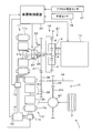
- FIG. 1 schematically shows a hybrid vehicle in which a control device according to one embodiment of the present invention is incorporated.
- vehicle 1 includes an internal combustion engine (hereinafter sometimes referred to as an engine) 10, a first motor / generator (hereinafter sometimes abbreviated as a first MG) 11, and a second motor / generator (hereinafter referred to as a first motor / generator). (It may be abbreviated as second MG.)
- the engine 10 is a known spark ignition type internal combustion engine mounted on a hybrid vehicle. Therefore, detailed description is omitted.
- the first MG 11 and the second MG 12 are well-known motor generators that function as an electric motor and a generator.
- the first MG 11 includes a rotor 11b that rotates integrally with the rotor shaft 11a, and a stator 11c that is coaxially disposed on the outer periphery of the rotor 11b and fixed to a case (not shown).
- the second MG 12 includes a rotor 12b that rotates integrally with the rotor shaft 12a, and a stator 12c that is coaxially disposed on the outer periphery of the rotor 12b and fixed to the case.
- First MG 11 is electrically connected to battery 14 via first inverter 13.
- the second MG 12 is electrically connected to the battery 14 via the second inverter 15.
- the vehicle 1 is provided with a power split mechanism 16 and an output unit 17 for transmitting power to the drive wheels 2 of the vehicle 1.
- the output unit 17 includes an output shaft 18 as an output member and an output gear 19 that rotates integrally with the output shaft 18.
- the output gear 19 meshes with a ring gear 20 a provided in the case of the differential mechanism 20.
- the differential mechanism 20 is a known mechanism that distributes the transmitted power to the left and right drive wheels 2.
- the power split mechanism 16 includes a planetary gear mechanism 21 as a differential mechanism.
- the planetary gear mechanism 21 is a single pinion type planetary gear mechanism.
- the planetary gear mechanism 21 includes a sun gear S, a ring gear R, a pinion gear P, and a carrier C.
- the sun gear S is an external gear.
- the ring gear R is an internal gear.
- the ring gear R is disposed coaxially with the sun gear S.
- the pinion gear P meshes with each of the sun gear S and the ring gear R.
- the carrier C supports the pinion gear P so that it can rotate and can revolve around the sun gear S. As shown in this figure, the carrier C is connected to the output shaft 10 a of the engine 10.
- Sun gear S is connected to rotor shaft 11a of first MG 11. Therefore, the carrier C corresponds to the first rotating element of the present invention, and the sun gear S corresponds to the second rotating element of the present invention.
- the power split mechanism 16 includes a dog clutch 22 as connection switching means.
- the dog clutch 22 includes a first engagement member 23, a second engagement member 24, a third engagement member 25, and a sleeve 26.
- the first engagement member 23 is fixed to the rotor shaft 11a of the first MG 11.
- the second engagement member 24 is connected to the ring gear R so as to rotate integrally.
- the third engagement member 25 is coupled to rotate integrally with the first drive gear 27.
- the output shaft 18 is provided with a driven gear 28 that rotates integrally with the output shaft 18.
- the first drive gear 27 meshes with the driven gear 28.
- a second drive gear 29 is provided on the rotor shaft 12 a of the second MG 12.
- the second drive gear 29 meshes with the driven gear 28. Therefore, the second MG 12 corresponds to the electric motor of the present invention.
- Dog teeth are provided on the outer peripheral surfaces of the first engagement member 23, the second engagement member 24, and the third engagement member 25.
- dog teeth capable of meshing with the dog teeth of the engaging members 23 to 25 are provided.
- the sleeve 26 is movably provided in a first position shown in FIG. 1, a second position shown in FIG. 2, and a third position shown in FIG. In the first position, the sleeve 26 engages with the first engagement member 23 and the second engagement member 24. On the other hand, the sleeve 26 does not engage with the third engagement member 25.
- this state is referred to as a first state.
- the sleeve 26 engages with the second engagement member 24 and the third engagement member 25.
- the sleeve 26 does not engage with the first engagement member 23. Therefore, in this state, the second engagement member 24 and the third engagement member 25 rotate together. And the 1st engagement member 23 becomes relative rotation with respect to these.
- this state is referred to as a second state.
- the sleeve 26 engages with all of the first engagement member 23, the second engagement member 24, and the third engagement member 25. Therefore, in this state, the 1st engagement member 23, the 2nd engagement member 24, and the 3rd engagement member 25 rotate integrally.
- this state is referred to as a third state.
- the dog clutch 22 When the dog clutch 22 is switched to the first state or the third state, the first engagement member 23 and the second engagement member 24 are connected. In this case, since the sun gear S and the ring gear R are connected, the sun gear S, the ring gear R, and the carrier C rotate together. Therefore, the gear ratio between the sun gear S and the ring gear R is fixed. On the other hand, when the dog clutch 22 is switched to the second state, the first engagement member 23 and the second engagement member 24 are disconnected. Therefore, in this case, the fixed gear ratio is released. Therefore, the first state and the third state correspond to the locked state of the present invention. The second state corresponds to the unlocked state of the present invention. The dog clutch 22 corresponds to the lock mechanism of the present invention.
- the dog clutch 22 when the dog clutch 22 is switched to the second state or the third state, the third engagement member 25 and the second engagement member 24 are connected. In this case, since the ring gear R and the first drive gear 27 are coupled, the ring gear R and the output shaft 18 are connected so that power can be transmitted. Therefore, the second state or the third state corresponds to the engaged state of the present invention.
- the dog clutch 22 when the dog clutch 22 is switched to the first state, the third engagement member 25 and the second engagement member 24 are disconnected. Therefore, in this case, the ring gear R and the output shaft 18 are disconnected. Therefore, the second state and the third state correspond to the engaged state of the present invention.
- the first state corresponds to the released state of the present invention.
- the dog clutch 22 corresponds to the clutch mechanism of the present invention.
- the ring gear R corresponds to the third rotating element of the present invention.
- the engine 10, the first MG 11, the second MG 12, and the dog clutch 22 are controlled by the vehicle control device 40.
- the vehicle control device 40 is configured as a computer unit including a microprocessor and peripheral devices such as RAM and ROM necessary for its operation.
- the vehicle control device 40 holds various control programs for causing the vehicle 1 to travel appropriately.
- the vehicle control device 40 executes control of the control target such as the engine 10 and the MGs 11 and 12 by executing these programs.
- the vehicle control device 40 controls the first MG 11 by controlling the first inverter 13. Further, the vehicle control device 40 controls the second MG 12 by controlling the second inverter 15.
- Various sensors for acquiring information relating to the vehicle 1 are connected to the vehicle control device 40.
- an accelerator opening sensor 41 for example, an accelerator opening sensor 41, a vehicle speed sensor 42, a battery sensor 43, and the like are connected to the vehicle control device 40.
- the accelerator opening sensor 41 outputs a signal corresponding to the depression amount of the accelerator pedal, that is, the accelerator opening.
- the vehicle speed sensor 42 outputs a signal corresponding to the speed (vehicle speed) of the vehicle 1.
- the battery sensor 43 outputs a signal corresponding to the state of charge of the battery 14.
- various sensors are connected to the vehicle control device 40, but their illustration is omitted.
- a plurality of travel modes are realized by appropriately controlling the engine 10, the first MG 11, the second MG 12, and the dog clutch 22.
- the EV mode, the parallel mode, and the series parallel mode are set as the plurality of travel modes.
- Each travel mode will be described with reference to FIGS.
- FIG. 4 shows an alignment chart in the EV mode.
- FIG. 5 shows an alignment chart in the parallel mode.
- FIG. 6 shows an alignment chart in the series parallel mode.
- “ENG” indicates the engine 10 and “OUT” indicates the output shaft 18.
- MG1” indicates the first MG11
- MG2 indicates the second MG12.
- S indicates the sun gear S
- R indicates the ring gear R
- C indicates the carrier C.
- the dog clutch 22 In the EV mode, the dog clutch 22 is switched to the first state. In this case, the third engagement member 25 is separated from the first engagement member 23 and the second engagement member 24. Therefore, the output unit 17 is separated from the power split mechanism 16 as shown in FIG. That is, the engine 10 and the first MG 11 are disconnected from the drive wheel 2. Therefore, in the EV mode, the drive wheel 2 is driven by the second MG 12.
- the dog clutch 22 When the dog clutch 22 is in the first state, the first engagement member 23 and the second engagement member 24 are connected. In this case, since the sun gear S and the ring gear R are connected, the sun gear S, the carrier C, and the ring gear R rotate together. Therefore, the first MG 11 can function as a generator, and the engine 10 can drive the first MG 11 to generate power.
- the driving method of the vehicle 1 is a series hybrid.
- the dog clutch 22 is switched to the third state.
- the first engagement member 23, the second engagement member 24, and the third engagement member 25 are all connected.
- the sun gear S and the ring gear R are coupled, so that the sun gear S, the carrier C, and the ring gear R rotate together.
- the first drive gear 27 is also connected thereto. Therefore, the output shaft 10a of the engine 10 and the first drive gear 27 rotate integrally. That is, the power output from the engine 10 is transmitted to the drive wheels 2. Therefore, in the parallel mode, the drive wheel 2 can be driven by the engine 10 and the second MG 12.
- the driving method of the vehicle 1 is a parallel hybrid.
- the dog clutch 22 is switched to the second state.
- the first engagement member 23 is separated from the second engagement member 24 and the third engagement member 25. Therefore, the sun gear S and the ring gear R are separated. Therefore, the sun gear S, the ring gear R, and the carrier C are in a state where they can rotate relative to each other.
- the 2nd engagement member 24 and the 3rd engagement member 25 are connected, the ring gear R and the 1st drive gear 27 rotate integrally. Therefore, in this case, the power output from the engine 10 can be divided into the first MG 11 and the first drive gear 27 as shown in FIG. Therefore, the drive wheel 2 can be driven by the engine 10 and the second MG 12 even in the series parallel mode. Further, the engine 10 can generate power by driving the first MG 11.
- the drive system of the vehicle 1 is a series / parallel hybrid.
- the vehicle control device 40 switches between these travel modes based on the map shown in FIG.
- This figure shows the relationship between the vehicle speed, the driving force required for the vehicle 1, and the travel mode.
- the series parallel mode region Rsp in this figure is a region where the traveling mode is switched to the series parallel mode.
- the parallel mode region Rp is a region where the traveling mode is switched to the parallel mode.
- the EV mode area Rev is an area where the traveling mode is switched to the EV mode.
- the relationship shown in this figure may be obtained in advance by experiment or numerical calculation and stored in the vehicle control device 40 as a map.
- an operation region between a predetermined first vehicle speed V1 and a predetermined second vehicle speed V2 and less than or equal to a predetermined determination driving force P is set.
- the EV mode area Rev is set so as to include an operation area that is less than the first vehicle speed V1 and equal to or less than the determination driving force P. Therefore, the first vehicle speed V1 corresponds to the determination speed of the present invention.
- the size of the EV mode area Rev is changed according to the state of charge of the battery 14 so as to decrease as the remaining amount of the battery 14 decreases.
- the vehicle control device 40 functions as the area changing means of the present invention.
- the vehicle control device 40 first acquires the traveling state of the vehicle 1 based on the vehicle speed and the driving force required for the vehicle 1. Thereafter, the travel mode is switched according to which region the acquired travel state is in. As shown in this figure, the EV mode region Rev when the state of charge of the battery 14 is high overlaps the parallel mode region Rp. When the traveling state of the vehicle 1 is in a portion where the region Rev and the region Rp overlap, the traveling mode is switched according to a predetermined rule set in advance. For example, when the region Rev and the region Rp overlap, the rule is set so that the EV mode is selected. Thus, the vehicle control device 40 functions as the control means of the present invention by switching the travel modes.
- the dog clutch 22 is in a different state in each travel mode. Therefore, when switching the travel mode, it is necessary to switch the state of the dog clutch 22.
- the vehicle control device 40 synchronizes the first engagement member 23 and the third engagement member 25 with the first MG 11. For example, when the dog clutch 22 is switched from the second state to the third state, the difference between the rotation speed of the first engagement member 23 and the rotation speed of the third engagement member 25 falls within a predetermined allowable range. The first MG 11 is controlled. Thereafter, the sleeve 26 is moved to the third position. Similarly, when switching the dog clutch 22 from the first state to the third state, the first engagement member 23 and the third engagement member 25 are synchronized by the first MG 11.
- the vehicle control device 40 cranks the engine 10 with the first MG 11 when a predetermined start condition for starting the engine 10 is satisfied when the traveling mode is the EV mode. Note that it is determined that the start condition is satisfied when, for example, the travel mode is switched from the EV mode to another travel mode, or when the first MG 11 needs to generate power. At this time, the vehicle control device 40 cranks the engine 10 by the first MG 11 with the dog clutch 22 in the first state. As a result, the engine 10 is started. By starting the engine 10 in this way, the vehicle control device 40 functions as the starting means of the present invention.
- the first engagement member 23 of the dog clutch 22 is provided on the rotor shaft 11 a of the first MG 11. Therefore, no gear or the like is interposed between the first MG 11 and the first engagement member 23. Therefore, when the first engagement member 23 is synchronized with the other engagement members 24 and 25, it is not affected by gear backlash or the like. Therefore, it is possible to suppress abnormal noise and vibration when switching the travel mode.
- the gear ratio between the sun gear S and the ring gear R can be fixed or released by the dog clutch 22.
- the dog clutch 22 can connect the ring gear R and the output shaft 18 so that power can be transmitted, or can cancel the connection.
- the switching can be performed by one dog clutch 22. Therefore, the apparatus can be reduced in size. Moreover, the mounting property to the vehicle 1 can thereby be improved.
- the engine 10 when the starting condition is satisfied when the traveling mode is the EV mode, the engine 10 is cranked by the first MG 11 with the dog clutch 22 in the first state. In this case, the output unit 17 is disconnected from the power split mechanism 16. Therefore, the vibration of the vehicle 1 when the engine 10 is started can be suppressed.
- the EV mode area Rev includes an operation area that is less than the first vehicle speed V1 and equal to or less than the determination driving force P
- the EV mode area Rev is switched to the EV mode when the vehicle 1 travels at a low torque and a low vehicle speed.
- the parallel mode region Rp includes an operation region in which the first vehicle speed V1 is equal to or higher than the determination driving force P
- the second MG 12 continues for a long time even if the vehicle 1 is driven for a long time with the determination driving force P or less. Driving can be suppressed.
- region Rev is changed according to the residual amount of the battery 14, the residual amount of the battery 14 is securable.
- the power split mechanism 16 may be provided with a lock mechanism 50 and a clutch mechanism 60.
- FIG. 8 shows an enlarged part of the power split mechanism 16. 8 that are the same as those in FIG. 1 are denoted by the same reference numerals and description thereof is omitted. Both the lock mechanism 50 and the clutch mechanism 60 are configured as dog clutches.
- the lock mechanism 50 includes a first rotating member 51, a second rotating member 52, and a sleeve 53.
- the first rotating member 51 is provided on the rotor shaft 11 a of the first MG 11.
- the second rotating member 52 is connected to the ring gear R.
- the sleeve 53 can move to a locked position where the first rotating member 51 and the second rotating member 52 are connected and an unlock position where the connection is released.
- the sleeve 53 in the locked position is shown above the rotor shaft 11a
- the sleeve 53 in the unlocked position is shown below the rotor shaft 11a.
- the case where the sleeve 53 is in the locked position is referred to as a locked state
- the case where the sleeve 53 is in the unlocked position is referred to as an unlocked state.
- the clutch mechanism 60 includes a first clutch member 61, a second clutch member 62, and a sleeve 63.
- the first clutch member 61 is connected to the ring gear R.
- the second clutch member 62 is connected to the first drive gear 27.
- the sleeve 63 can move between an engagement position for connecting the first clutch member 61 and the second clutch member 62 and a release position for releasing the connection.
- the sleeve 63 in the engagement position is shown above the rotor shaft 11a
- the sleeve 63 in the release position is shown below the rotor shaft 11a.
- the case where the sleeve 63 is in the engagement position is referred to as an engagement state
- the case where the sleeve 63 is in the release position is referred to as a release state.
- the driving mode is switched by switching the state of the lock mechanism 50 and the state of the clutch mechanism 60.
- the lock mechanism 50 In the EV mode, the lock mechanism 50 is switched to the locked state, and the clutch mechanism 60 is switched to the released state.
- the parallel mode In the parallel mode, the lock mechanism 50 is switched to the locked state, and the clutch mechanism 60 is switched to the engaged state.
- the series parallel mode the lock mechanism 50 is switched to the unlocked state, and the clutch mechanism 60 is switched to the released state.
- the present invention can be implemented in various forms without being limited to the above-described forms.
- the internal combustion engine of the hybrid vehicle to which the present invention is applied may be a diesel engine.
- An electric motor may be provided instead of the second MG.
- the planetary gear mechanism included in the power split mechanism is not limited to the single pinion type planetary gear mechanism.
- a double pinion type planetary gear mechanism may be provided in the power split mechanism.
Landscapes
- Engineering & Computer Science (AREA)
- Chemical & Material Sciences (AREA)
- Combustion & Propulsion (AREA)
- Transportation (AREA)
- Mechanical Engineering (AREA)
- Electric Propulsion And Braking For Vehicles (AREA)
- Hybrid Electric Vehicles (AREA)
Abstract
ドグクラッチ(22)の状態を切り替えることにより走行モードを切り替え可能なハイブリッド車両(1A)に適用される制御装置において、バッテリ(14)の充電状態、車両(1A)に要求されている駆動力及び車両(1A)の速度に基づいて走行モードが切り替えられるようにドグクラッチ(22)、内燃機関(10)、第1MG(11)及び第2MG(12)が制御され、ドグクラッチ(22)は、第1MG(11)のロータ軸(11a)に設けられた第1係合部材(23)と、リングギヤ(R)と一体に回転する第2係合部材(24)とを備え、第1状態及び第3状態では第1係合部材(23)と第2係合部材(24)とが連結され、第2状態では第1係合部材(23)と第2係合部材(24)との連結が解除される。
Description
本発明は、走行用駆動源として内燃機関と電動機とが搭載され、走行モードを内燃機関を駆動輪から切り離して電動機で走行するEVモード、主に内燃機関で走行するパラレルモード、及び内燃機関の動力を駆動輪と発電機とに分割するシリーズパラレルモードに切り替え可能なハイブリッド車両に適用される制御装置に関する。
走行用駆動源として内燃機関と電動機とが搭載されたハイブリッド車両が知られている。また、ハイブリッド車両の駆動方式として、例えばシリーズハイブリッド、パラレルハイブリッド、及びシリーズパラレルハイブリッド等が知られている。そして、車速及びトルクに応じてこれら駆動方式を切り替え可能に構成されたハイブリッド車両が知られている(特許文献1参照)。その他、本発明に関連する先行技術文献として特許文献2が存在する。
特許文献1の図18に示されているハイブリッド車両では、遊星歯車機構のリングギヤとモータとの間に第1クラッチが設けられている。また、遊星歯車機構のリングギヤとキャリアとの間に第2クラッチが設けられている。そして、このハイブリッド車両では、これら2つのクラッチの状態を切り替えることで駆動方式を切り替えている。そして、これにより車両の走行モードを切り替えている。車両の駆動装置に設けられるクラッチとして、係合時に同期制御が必要なクラッチ、例えばドグクラッチが知られている。特許文献1のこのハイブリッド車両において、このような同期制御が必要なクラッチが第1クラッチ及び第2クラッチとして設けられた場合、遊星歯車機構のサンギヤと連結されたモータで同期制御が行われる。この場合、リングギヤ又はキャリアの回転数制御は遊星歯車機構を介して行われる。そのため、同期制御は、遊星歯車機構の各部のバックラッシュ等の影響を受ける。従って、走行モードの切替時に異音及び振動が発生するおそれがある。
そこで、本発明は、走行モードの切替時における異音及び振動を抑制することが可能なハイブリッド車両の制御装置を提供することを目的とする。
本発明の制御装置は、内燃機関と、電動機及び発電機として機能するモータ・ジェネレータと、駆動輪と動力伝達可能に接続された出力部材と、前記出力部材に動力を出力可能な電動機と、前記電動機及び前記モータ・ジェネレータと電気的に接続されたバッテリと、相互に差動回転可能な少なくとも3つの回転要素を有し、前記3つの回転要素のうちの第1回転要素が前記内燃機関の出力軸と接続され、前記3つの回転要素のうちの第2回転要素が前記モータ・ジェネレータのロータ軸と接続された差動機構と、前記3つの回転要素のうちの第3回転要素と前記出力部材とが動力伝達可能に接続された係合状態と、前記第3回転要素と前記出力部材とが切り離された解放状態とに切り替え可能なクラッチ機構と、前記第1回転要素と前記第2回転要素との間の変速比を固定するロック状態と、前記変速比の固定を解除するアンロック状態とに切り替え可能なロック機構と、を備え、前記クラッチ機構を前記解放状態に切り替え、前記電動機で前記駆動輪を駆動するEVモードと、前記ロック機構を前記ロック状態に切り替えるとともに前記クラッチ機構を前記係合状態に切り替え、前記内燃機関及び前記電動機の少なくともいずれか一方で前記駆動輪を駆動するパラレルモードと、前記ロック機構を前記アンロック状態に切り替えるとともに前記クラッチ機構を前記係合状態に切り替え、前記内燃機関及び前記電動機の少なくともいずれか一方で前記駆動輪を駆動するシリーズパラレルモードと、に走行モードを切り替え可能なハイブリッド車両に適用され、前記バッテリの充電状態、前記車両に要求されている駆動力及び前記車両の速度に基づいて前記車両の走行モードが切り替えられるように前記クラッチ機構、前記ロック機構、前記内燃機関及び前記電動機を制御する制御手段を備え、前記ロック機構は、前記モータ・ジェネレータのロータ軸に設けられた第1回転部材と、前記第3回転要素と一体に回転する第2回転部材と、を備え、前記ロック状態では前記第1回転部材と前記第2回転部材とを連結し、前記アンロック状態では前記第1回転部材と前記第2回転部材との連結を解除する。
本発明の制御装置では、ロック機構の第1回転部材がモータ・ジェネレータのロータ軸に設けられているので、第1回転部材とモータ・ジェネレータとの間にギヤ等が介在していない。そのため、モータ・ジェネレータにて第1回転部材を第2回転部材と同期させる場合に、ギヤのバックラッシュ等の影響を受けない。従って、走行モードの切替時における異音及び振動を抑制できる。
本発明の制御装置の一形態においては、前記第1回転部材としての第1係合部材と、前記第2回転部材としての第2係合部材と、前記出力部材と一体に回転する第3係合部材と、を有し、前記第1係合部材と前記第2係合部材とが一体に回転し、かつ前記第3係合部材が切り離される第1状態と、前記第2係合部材と前記第3係合部材とが一体に回転し、かつ前記第1係合部材が切り離される第2状態と、前記第1係合部材、前記第2係合部材及び前記第3係合部材が一体に回転する第3状態と、に切り替え可能な接続切替手段が設けられ、前記クラッチ機構及び前記ロック機構は、前記接続切替手段であってもよい。この形態では、接続切替手段を第1状態又は第3状態に切り替えることにより、第2回転要素と第3回転要素とを接続できる。一方、接続切替手段を第2状態に切り替えることにより、第2回転要素と第3回転要素との接続を解除できる。また、接続切替手段を第2状態又は第3状態に切り替えることにより、第3回転要素と出力部材とを動力伝達可能に接続できる。一方、接続切替手段を第1状態に切り替えることにより、第3回転要素と出力部材とを切り離すことができる。このようにこの形態によれば、接続切替手段により、第2回転要素と第3回転要素との接続及びその接続の解除を切り替えることができる。また、同じ接続切替手段により、第3回転要素と出力部材との接続及びその接続の解除を切り替えることができる。そのため、装置を小型化できる。また、これにより車両への搭載性を向上させることができる。
この形態においては、前記差動機構としてシングルピニオン型の遊星歯車機構が設けられ、前記第1回転要素が前記遊星歯車機構のキャリアであり、前記第2回転要素が前記遊星歯車機構のサンギヤであり、前記第3回転要素が前記遊星歯車機構のリングギヤであり、前記制御手段は、前記EVモードにおいて前記接続切替手段を前記第1状態に切り替え、前記車両の走行モードがEVモードのときに前記内燃機関を始動すべき所定の始動条件が成立した場合、前記接続切替手段を前記第1状態にした状態で前記モータ・ジェネレータにより前記内燃機関をクランキングして前記内燃機関を始動する始動手段をさらに備えていてもよい。接続切替手段が第1状態のときには、第3回転要素と出力部材とを切り離すことができる。この形態では、この状態で内燃機関をクランキングするので、内燃機関の始動時における車両の振動を抑制できる。
本発明の制御装置の一形態において、前記制御手段は、前記車両の速度及び前記車両に要求されている駆動力にて特定される前記車両の走行状態が所定のEVモード領域内にある場合に前記車両の走行モードを前記EVモードに切り替え、前記車両の走行状態が所定のパラレルモード領域内にある場合に前記車両の走行モードを前記パラレルモードに切り替え、前記パラレルモード領域には、所定の判定速度以上、かつ所定の判定駆動力以下の運転領域が含まれ、前記EVモード領域には、前記判定速度未満、かつ前記判定駆動力以下の運転領域が含まれている。この形態によれば、車両が低トルクかつ低車速で走行する場合にEVモードに切り替えられる。この場合、内燃機関が低速で運転されることを抑制できるので、燃費を改善できる。また、パラレルモード領域には判定速度以上、かつ判定駆動力以下の運転領域が含まれている。そのため、車両が判定駆動力以下で長時間運転されたとしても電動機が長時間連続して運転されることを抑制できる。
この形態において、前記制御手段は、前記バッテリの残量が少ないほど前記EVモード領域が小さくなるように前記バッテリの充電状態に応じて前記EVモード領域の大きさを変更する領域変更手段を備えていてもよい。このようにEVモード領域の大きさを変更することにより、バッテリの残量を確保することができる。
図1は、本発明の一形態に係る制御装置が組み込まれたハイブリッド車両を概略的に示している。この車両1は、内燃機関(以下、エンジンと称することがある。)10と、第1モータ・ジェネレータ(以下、第1MGと略称することがある。)11と、第2モータ・ジェネレータ(以下、第2MGと略称することがある。)12とを備えている。エンジン10は、ハイブリッド車両に搭載される周知の火花点火式内燃機関である。そのため、詳細な説明を省略する。
第1MG11及び第2MG12は、電動機及び発電機として機能する周知のモータ・ジェネレータである。第1MG11は、ロータ軸11aと一体回転するロータ11bと、ロータ11bの外周に同軸に配置されてケース(不図示)に固定されたステータ11cとを備えている。第2MG12も同様に、ロータ軸12aと一体回転するロータ12bと、ロータ12bの外周に同軸に配置されてケースに固定されたステータ12cとを備えている。第1MG11は、第1インバータ13を介してバッテリ14と電気的に接続されている。第2MG12は、第2インバータ15を介してバッテリ14と電気的に接続されている。
車両1には、動力分割機構16と、車両1の駆動輪2に動力を伝達するための出力部17とが設けられている。出力部17は、出力部材としての出力軸18と、出力軸18と一体に回転する出力ギヤ19とを備えている。出力ギヤ19は、デファレンシャル機構20のケースに設けられたリングギヤ20aと噛み合っている。デファレンシャル機構20は、伝達された動力を左右の駆動輪2に分配する周知の機構である。
動力分割機構16は、差動機構としての遊星歯車機構21を備えている。遊星歯車機構21は、シングルピニオン型の遊星歯車機構である。遊星歯車機構21は、サンギヤSと、リングギヤRと、ピニオンギヤPと、キャリアCとを備えている。サンギヤSは、外歯歯車である。リングギヤRは、内歯歯車である。リングギヤRは、サンギヤSに対して同軸的に配置されている。ピニオンギヤPは、サンギヤS及びリングギヤRのそれぞれと噛み合っている。キャリアCは、ピニオンギヤPを自転可能かつサンギヤSの周囲を公転可能に支持している。この図に示すようにキャリアCは、エンジン10の出力軸10aと連結されている。サンギヤSは、第1MG11のロータ軸11aと連結されている。そのため、キャリアCが本発明の第1回転要素に相当し、サンギヤSが本発明の第2回転要素に相当する。
また、動力分割機構16は、接続切替手段としてのドグクラッチ22を備えている。ドグクラッチ22は、第1係合部材23と、第2係合部材24と、第3係合部材25と、スリーブ26とを備えている。第1係合部材23は、第1MG11のロータ軸11aに固定されている。第2係合部材24は、リングギヤRと一体回転するように連結されている。第3係合部材25は、第1ドライブギヤ27と一体回転するように連結されている。出力軸18には、出力軸18と一体に回転するドリブンギヤ28が設けられている。第1ドライブギヤ27は、そのドリブンギヤ28と噛み合っている。第2MG12のロータ軸12aには、第2ドライブギヤ29が設けられている。第2ドライブギヤ29は、ドリブンギヤ28と噛み合っている。そのため、第2MG12が本発明の電動機に相当する。
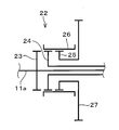
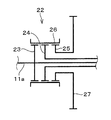
第1係合部材23、第2係合部材24、及び第3係合部材25のそれぞれの外周面にはドグ歯(不図示)が設けられている。スリーブ26の内周面には、それら係合部材23~25のドグ歯と噛み合うことが可能なドグ歯(不図示)が設けられている。そして、これらドグ歯が噛み合うことによりスリーブ26と各係合部材23~25とが係合する。スリーブ26は、図1に示す第1位置と、図2に示す第2位置と、図3に示す第3位置とに移動可能に設けられている。第1位置において、スリーブ26は第1係合部材23及び第2係合部材24と係合する。一方、スリーブ26は第3係合部材25とは係合しない。そのため、この状態では、第1係合部材23と第2係合部材24とが一体に回転する。そして、第3係合部材25は、これらに対して相対回転可能になる。以下、この状態を第1状態と称する。第2位置において、スリーブ26は第2係合部材24及び第3係合部材25と係合する。一方、スリーブ26は第1係合部材23とは係合しない。そのため、この状態では、第2係合部材24と第3係合部材25とが一体に回転する。そして、第1係合部材23は、これらに対して相対回転可能になる。以下、この状態を第2状態と称する。第3位置において、スリーブ26は第1係合部材23、第2係合部材24及び第3係合部材25の全てと係合する。そのため、この状態では、第1係合部材23、第2係合部材24及び第3係合部材25が一体に回転する。以下、この状態を第3状態と称する。
ドグクラッチ22が第1状態又は第3状態に切り替えられた場合、第1係合部材23と第2係合部材24とが連結される。この場合、サンギヤSとリングギヤRとが連結されるので、サンギヤS、リングギヤR及びキャリアCが一体に回転する。そのため、サンギヤSとリングギヤRとの間の変速比が固定される。一方、ドグクラッチ22が第2状態に切り替えられた場合には、第1係合部材23と第2係合部材24とが切り離される。そのため、この場合には変速比の固定が解除される。従って、第1状態及び第3状態が本発明のロック状態に相当する。また、第2状態が本発明のアンロック状態に相当する。そして、ドグクラッチ22が本発明のロック機構に相当する。また、ドグクラッチ22が第2状態又は第3状態に切り替えられた場合、第3係合部材25と第2係合部材24とが連結される。この場合、リングギヤRと第1ドライブギヤ27とが連結されるので、リングギヤRと出力軸18とが動力伝達可能に接続される。そのため、第2状態又は第3状態が本発明の係合状態に相当する。一方、ドグクラッチ22が第1状態に切り替えられた場合には、第3係合部材25と第2係合部材24とが切り離される。そのため、この場合にはリングギヤRと出力軸18とが切り離される。従って、第2状態及び第3状態が本発明の係合状態に相当する。また、第1状態が本発明の解放状態に相当する。そして、ドグクラッチ22が本発明のクラッチ機構に相当する。リングギヤRが本発明の第3回転要素に相当する。
エンジン10、第1MG11、第2MG12及びドグクラッチ22は、車両制御装置40により制御される。車両制御装置40は、マイクロプロセッサ及びその動作に必要なRAM、ROM等の周辺機器を含んだコンピュータユニットとして構成されている。車両制御装置40は、車両1を適切に走行させるための各種制御プログラムを保持している。車両制御装置40は、これらのプログラムを実行することによりエンジン10及び各MG11、12等の制御対象に対する制御を行っている。車両制御装置40は、第1インバータ13を制御することにより第1MG11を制御する。また、車両制御装置40は、第2インバータ15を制御することにより第2MG12を制御する。車両制御装置40には、車両1に係る情報を取得するための種々のセンサが接続されている。例えば、アクセル開度センサ41、車速センサ42及びバッテリセンサ43等が車両制御装置40に接続されている。アクセル開度センサ41は、アクセルペダルの踏み込み量、すなわちアクセル開度に対応した信号を出力する。車速センサ42は、車両1の速度(車速)に対応した信号を出力する。バッテリセンサ43は、バッテリ14の充電状態に対応した信号を出力する。この他にも車両制御装置40には種々のセンサが接続されているが、それらの図示は省略した。
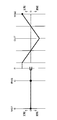
この車両1では、エンジン10、第1MG11、第2MG12及びドグクラッチ22を適宜に制御することにより複数の走行モードが実現される。複数の走行モードとしては、EVモード、パラレルモード及びシリーズパラレルモードが設定されている。図4~図6を参照して各走行モードについて説明する。なお、図4はEVモードにおける共線図を示している。図5はパラレルモードにおける共線図を示している。図6はシリーズパラレルモードにおける共線図を示している。なお、これらの図中の「ENG」はエンジン10を示し、「OUT」は出力軸18を示している。また、「MG1」は第1MG11を示し、「MG2」は第2MG12を示している。そして、「S」はサンギヤSを示し、「R」はリングギヤRを示し、「C」はキャリアCを示している。
EVモードでは、ドグクラッチ22を第1状態に切り替える。この場合、第3係合部材25が第1係合部材23及び第2係合部材24と切り離される。そのため、図4に示すように出力部17が動力分割機構16と切り離される。すなわち、エンジン10及び第1MG11が駆動輪2から切り離される。従って、EVモードでは駆動輪2は第2MG12により駆動される。ドグクラッチ22が第1状態の場合には、第1係合部材23と第2係合部材24とが連結される。この場合、サンギヤSとリングギヤRとが連結されるので、サンギヤS、キャリアC及びリングギヤRは一体に回転する。従って、第1MG11を発電機として機能させ、エンジン10で第1MG11を駆動することにより発電を行うことができる。なお、図4はエンジン10及び第1MG11が停止しているときの共線図である。このようにEVモードでは、第2MG12で駆動輪2を駆動しつつ第1MG11で発電できる。すなわち、このEVモードでは、車両1の駆動方式がシリーズハイブリッドになる。
パラレルモードでは、ドグクラッチ22を第3状態に切り替える。この場合、第1係合部材23、第2係合部材24及び第3係合部材25が全て連結される。これによりサンギヤSとリングギヤRとが連結されるので、サンギヤS、キャリアC及びリングギヤRが一体に回転する。また、この場合には第1ドライブギヤ27もこれらと連結される。そのため、エンジン10の出力軸10aと第1ドライブギヤ27とが一体に回転する。すなわち、エンジン10から出力された動力が駆動輪2に伝達される。従って、パラレルモードでは、駆動輪2をエンジン10及び第2MG12で駆動できる。このようにパラレルモードでは、車両1の駆動方式がパラレルハイブリッドになる。
シリーズパラレルモードでは、ドグクラッチ22を第2状態に切り替える。この場合、第1係合部材23が第2係合部材24及び第3係合部材25と切り離される。そのため、サンギヤSとリングギヤRとが切り離される。従って、サンギヤS、リングギヤR及びキャリアCは、互いに相対回転可能な状態になる。そして、第2係合部材24と第3係合部材25とは連結されるので、リングギヤRと第1ドライブギヤ27とが一体に回転する。そのため、この場合には図6に示すようにエンジン10から出力されたパワーを第1MG11と第1ドライブギヤ27とに分割することができる。従って、シリーズパラレルモードでも、駆動輪2をエンジン10及び第2MG12で駆動できる。また、エンジン10で第1MG11を駆動することにより発電を行うことができる。このようにシリーズパラレルモードでは、車両1の駆動方式がシリーズパラレルハイブリッドになる。
車両制御装置40は、図7に示したマップに基づいてこれらの走行モードを切り替える。この図は、車速と、車両1に要求されている駆動力と、走行モードとの関係を示している。この図のシリーズパラレルモード領域Rspは、走行モードがシリーズパラレルモードに切り替えられる領域である。パラレルモード領域Rpは、走行モードがパラレルモードに切り替えられる領域である。EVモード領域Revは、走行モードがEVモードに切り替えられる領域である。なお、この図に示した関係は、予め実験又は数値計算等により求めて車両制御装置40にマップとして記憶させておけばよい。
この図に示すようにパラレルモード領域Rpには、所定の第1車速V1から所定の第2車速V2の間であり、かつ所定の判定駆動力P以下の運転領域が設定されている。EVモード領域Revは、第1車速V1未満かつ判定駆動力P以下の運転領域が含まれるように設定されている。そのため、第1車速V1が本発明の判定速度に相当する。この図に示すようにEVモード領域Revの大きさは、バッテリ14の残量が少ないほど小さくなるようにバッテリ14の充電状態に応じて変更される。バッテリ14の充電状態が高い場合、言い換えるとバッテリ14の残量が多い場合には、線Lhで囲まれる範囲がEVモード領域Revに設定される。一方、バッテリ14のSOCが低い場合、言い換えるとバッテリ14の残量が少ない場合には、線Llで囲まれる範囲がEVモード領域Revに設定される。このようにEVモード領域を変更することにより、車両制御装置40が本発明の領域変更手段として機能する。
車両制御装置40は、まず車速及び車両1に要求されている駆動力に基づいて車両1の走行状態を取得する。その後、取得した走行状態がいずれの領域にあるかに応じて走行モードを切り替える。なお、この図に示すように、バッテリ14の充電状態が高いときのEVモード領域Revはパラレルモード領域Rpと重なっている。車両1の走行状態がこの領域Revと領域Rpとが重なる部分内にある場合には、予め設定した所定の規則に従って走行モードが切り替えられる。例えば、領域Revと領域Rpとが重なっている場合には、EVモードが選択されるように規則が設定される。このように走行モードを切り替えることにより、車両制御装置40が本発明の制御手段として機能する。
上述したように各走行モードでは、ドグクラッチ22の状態が互いに異なる。そのため、走行モードを切り替える場合には、ドグクラッチ22の状態を切り替える必要がある。この際、車両制御装置40は、第1MG11で第1係合部材23と第3係合部材25とを同期させる。例えば、ドグクラッチ22を第2状態から第3状態に切り替える場合には、第1係合部材23の回転数と第3係合部材25の回転数との差が所定の許容範囲内に収まるように第1MG11を制御する。その後、スリーブ26を第3位置に動かす。ドグクラッチ22を第1状態から第3状態に切り替える場合にも同様に第1MG11で第1係合部材23と第3係合部材25とを同期させる。
また、車両制御装置40は、走行モードがEVモードのときにエンジン10を始動すべき所定の始動条件が成立した場合には、第1MG11でエンジン10をクランキングする。なお、始動条件は、例えば走行モードをEVモードから他の走行モードに切り替える場合、又は第1MG11で発電する必要がある場合等に成立したと判定される。この際、車両制御装置40は、ドグクラッチ22を第1状態にした状態で第1MG11によりエンジン10をクランキングする。そして、これによりエンジン10を始動する。このようにエンジン10を始動することにより車両制御装置40が本発明の始動手段として機能する。
以上に説明したように、本発明では、ドグクラッチ22の第1係合部材23が第1MG11のロータ軸11aに設けられている。そのため、第1MG11と第1係合部材23との間にギヤなどが介在していない。そのため、第1係合部材23を他の係合部材24、25と同期させる場合にギヤのバックラッシュ等の影響を受けない。従って、走行モードの切替時における異音及び振動を抑制できる。
また、ドグクラッチ22によりサンギヤSとリングギヤRとの間の変速比を固定したりその固定を解除したりできる。また、このドグクラッチ22でリングギヤRと出力軸18とを動力伝達可能に接続したりその接続を解除したりできる。このように本発明によれば、1つのドグクラッチ22でこれらの切り替えを行うことができる。そのため、装置を小型化できる。また、これにより車両1への搭載性を向上させることができる。
本発明では、走行モードがEVモードのときに始動条件が成立した場合には、ドグクラッチ22を第1状態にした状態で第1MG11によりエンジン10をクランキングする。この場合、出力部17が動力分割機構16と切り離される。そのため、エンジン10の始動時における車両1の振動を抑制できる。
EVモード領域Revは、第1車速V1未満かつ判定駆動力P以下の運転領域が含まれているので、車両1が低トルクかつ低車速で走行する場合にEVモードに切り替えられる。これによりエンジン10が低速で運転されることを抑制できるので、燃費を改善できる。また、パラレルモード領域Rpには、第1車速V1以上かつ判定駆動力P以下の運転領域が含まれるので、車両1が判定駆動力P以下で長時間運転されたとしても第2MG12が長時間連続して運転されることを抑制できる。そして、EVモード領域Revの大きさをバッテリ14の残量に応じて変更するので、バッテリ14の残量を確保することができる。
なお、サンギヤSとリングギヤRとの間の変速比の固定及びその固定の解除を切り替える機構と、リングギヤRと出力軸18との接続及びその接続の解除を切り替える機構とは別々に設けられていてもよい。例えば、図8に示すように動力分割機構16にロック機構50及びクラッチ機構60を設けてもよい。図8は、動力分割機構16の一部を拡大して示している。なお、図8において図1と共通の部分には同一の符号を付して説明を省略する。ロック機構50及びクラッチ機構60は、いずれもドグクラッチとして構成されている。
ロック機構50は、第1回転部材51と、第2回転部材52と、スリーブ53とを備えている。第1回転部材51は、第1MG11のロータ軸11aに設けられている。第2回転部材52は、リングギヤRと連結されている。スリーブ53は、第1回転部材51と第2回転部材52とを連結するロック位置と、その連結を解除するアンロック位置とに移動できる。この図では、ロータ軸11aの上側にロック位置におけるスリーブ53を示し、ロータ軸11aの下側にアンロック位置におけるスリーブ53を示した。以下ではスリーブ53がロック位置にある場合をロック状態と称し、スリーブ53がアンロック位置にある場合をアンロック状態と称する。
クラッチ機構60は、第1クラッチ部材61と、第2クラッチ部材62と、スリーブ63とを備えている。第1クラッチ部材61は、リングギヤRと連結されている。第2クラッチ部材62は第1ドライブギヤ27と連結されている。スリーブ63は、第1クラッチ部材61と第2クラッチ部材62とを連結する係合位置と、その連結を解除する解放位置とに移動できる。この図では、ロータ軸11aの上側に係合位置におけるスリーブ63を示し、ロータ軸11aの下側に解放位置におけるスリーブ63を示した。以下ではスリーブ63が係合位置にある場合を係合状態と称し、スリーブ63が解放位置にある場合を解放状態と称する。
この変形例では、これらロック機構50の状態及びクラッチ機構60の状態を切り替えることにより、走行モードの切り替えが行われる。EVモードでは、ロック機構50がロック状態に切り替えられ、かつクラッチ機構60が解放状態に切り替えられる。パラレルモードでは、ロック機構50がロック状態に切り替えられ、かつクラッチ機構60が係合状態に切り替えられる。シリーズパラレルモードでは、ロック機構50がアンロック状態に切り替えられ、かつクラッチ機構60が解放状態に切り替えられる。このようにロック機構50の状態及びクラッチ機構60の状態を切り替えることにより、上述した形態と同様の動力伝達経路を形成することができる。そして、これら走行モードの切り替えは、上述した形態と同様に図7に示したマップに基づいて行われる。
この変形例では、ロック機構50の第1回転部材51を第1MG11のロータ軸11aに設けたので、第1回転部材51を第2回転部材52と同期させる場合にギヤのバックラッシュ等の影響を受けない。従って、走行モードの切替時における異音及び振動を抑制できる。
本発明は、上述した形態に限定されることなく、種々の形態にて実施することができる。例えば、本発明が適用されるハイブリッド車両の内燃機関は、ディーゼル機関でもよい。また、第2MGの代わりに電動機が設けられていてもよい。動力分割機構が備える遊星歯車機構は、シングルピニオン型の遊星歯車機構に限定されない。ダブルピニオン型の遊星歯車機構が動力分割機構に設けられてもよい。
Claims (5)
- 内燃機関と、
電動機及び発電機として機能するモータ・ジェネレータと、
駆動輪と動力伝達可能に接続された出力部材と、
前記出力部材に動力を出力可能な電動機と、
前記電動機及び前記モータ・ジェネレータと電気的に接続されたバッテリと、
相互に差動回転可能な少なくとも3つの回転要素を有し、前記3つの回転要素のうちの第1回転要素が前記内燃機関の出力軸と接続され、前記3つの回転要素のうちの第2回転要素が前記モータ・ジェネレータのロータ軸と接続された差動機構と、
前記3つの回転要素のうちの第3回転要素と前記出力部材とが動力伝達可能に接続された係合状態と、前記第3回転要素と前記出力部材とが切り離された解放状態とに切り替え可能なクラッチ機構と、
前記第1回転要素と前記第2回転要素との間の変速比を固定するロック状態と、前記変速比の固定を解除するアンロック状態とに切り替え可能なロック機構と、
を備え、
前記クラッチ機構を前記解放状態に切り替え、前記電動機で前記駆動輪を駆動するEVモードと、前記ロック機構を前記ロック状態に切り替えるとともに前記クラッチ機構を前記係合状態に切り替え、前記内燃機関及び前記電動機の少なくともいずれか一方で前記駆動輪を駆動するパラレルモードと、前記ロック機構を前記アンロック状態に切り替えるとともに前記クラッチ機構を前記係合状態に切り替え、前記内燃機関及び前記電動機の少なくともいずれか一方で前記駆動輪を駆動するシリーズパラレルモードと、に走行モードを切り替え可能なハイブリッド車両に適用され、
前記バッテリの充電状態、前記車両に要求されている駆動力及び前記車両の速度に基づいて前記車両の走行モードが切り替えられるように前記クラッチ機構、前記ロック機構、前記内燃機関及び前記電動機を制御する制御手段を備え、
前記ロック機構は、前記モータ・ジェネレータのロータ軸に設けられた第1回転部材と、前記第3回転要素と一体に回転する第2回転部材と、を備え、前記ロック状態では前記第1回転部材と前記第2回転部材とを連結し、前記アンロック状態では前記第1回転部材と前記第2回転部材との連結を解除する制御装置。 - 前記第1回転部材としての第1係合部材と、前記第2回転部材としての第2係合部材と、前記出力部材と一体に回転する第3係合部材と、を有し、前記第1係合部材と前記第2係合部材とが一体に回転し、かつ前記第3係合部材が切り離される第1状態と、前記第2係合部材と前記第3係合部材とが一体に回転し、かつ前記第1係合部材が切り離される第2状態と、前記第1係合部材、前記第2係合部材及び前記第3係合部材が一体に回転する第3状態と、に切り替え可能な接続切替手段が設けられ、
前記クラッチ機構及び前記ロック機構は、前記接続切替手段である請求項1に記載の制御装置。 - 前記差動機構としてシングルピニオン型の遊星歯車機構が設けられ、前記第1回転要素が前記遊星歯車機構のキャリアであり、前記第2回転要素が前記遊星歯車機構のサンギヤであり、前記第3回転要素が前記遊星歯車機構のリングギヤであり、
前記制御手段は、前記EVモードにおいて前記接続切替手段を前記第1状態に切り替え、
前記車両の走行モードがEVモードのときに前記内燃機関を始動すべき所定の始動条件が成立した場合、前記接続切替手段を前記第1状態にした状態で前記モータ・ジェネレータにより前記内燃機関をクランキングして前記内燃機関を始動する始動手段をさらに備えている請求項2に記載の制御装置。 - 前記制御手段は、前記車両の速度及び前記車両に要求されている駆動力にて特定される前記車両の走行状態が所定のEVモード領域内にある場合に前記車両の走行モードを前記EVモードに切り替え、前記車両の走行状態が所定のパラレルモード領域内にある場合に前記車両の走行モードを前記パラレルモードに切り替え、
前記パラレルモード領域には、所定の判定速度以上、かつ所定の判定駆動力以下の運転領域が含まれ、
前記EVモード領域には、前記判定速度未満、かつ前記判定駆動力以下の運転領域が含まれている請求項1~3のいずれか一項に記載の制御装置。 - 前記制御手段は、前記バッテリの残量が少ないほど前記EVモード領域が小さくなるように前記バッテリの充電状態に応じて前記EVモード領域の大きさを変更する領域変更手段を備えている請求項4に記載の制御装置。
Priority Applications (1)
| Application Number | Priority Date | Filing Date | Title |
|---|---|---|---|
| PCT/JP2012/064805 WO2013183164A1 (ja) | 2012-06-08 | 2012-06-08 | ハイブリッド車両の制御装置 |
Applications Claiming Priority (1)
| Application Number | Priority Date | Filing Date | Title |
|---|---|---|---|
| PCT/JP2012/064805 WO2013183164A1 (ja) | 2012-06-08 | 2012-06-08 | ハイブリッド車両の制御装置 |
Publications (1)
| Publication Number | Publication Date |
|---|---|
| WO2013183164A1 true WO2013183164A1 (ja) | 2013-12-12 |
Family
ID=49711580
Family Applications (1)
| Application Number | Title | Priority Date | Filing Date |
|---|---|---|---|
| PCT/JP2012/064805 Ceased WO2013183164A1 (ja) | 2012-06-08 | 2012-06-08 | ハイブリッド車両の制御装置 |
Country Status (1)
| Country | Link |
|---|---|
| WO (1) | WO2013183164A1 (ja) |
Cited By (3)
| Publication number | Priority date | Publication date | Assignee | Title |
|---|---|---|---|---|
| DE102015203571A1 (de) | 2015-02-27 | 2016-09-01 | Zf Friedrichshafen Ag | Kupplungsvorrichtung |
| JP2019059323A (ja) * | 2017-09-26 | 2019-04-18 | 株式会社Subaru | ハイブリッド車両のパワーユニット |
| FR3111591A1 (fr) * | 2020-06-18 | 2021-12-24 | Renault | Transmission infiniment variable a train diviseur de puissance et procede de commande |
Citations (5)
| Publication number | Priority date | Publication date | Assignee | Title |
|---|---|---|---|---|
| JPH0937411A (ja) * | 1995-07-19 | 1997-02-07 | Aisin Aw Co Ltd | 車輌用駆動装置 |
| JP2006170336A (ja) * | 2004-12-16 | 2006-06-29 | Nissan Motor Co Ltd | ハイブリッド変速機のモード切り替え制御装置 |
| JP2010036880A (ja) * | 2008-07-11 | 2010-02-18 | Aisin Aw Co Ltd | ハイブリッド駆動装置 |
| JP2012046115A (ja) * | 2010-08-27 | 2012-03-08 | Toyota Motor Corp | 車両用ハイブリッド駆動装置 |
| JP2012081793A (ja) * | 2010-10-07 | 2012-04-26 | Toyota Motor Corp | ハイブリッド車両の制御装置 |
-
2012
- 2012-06-08 WO PCT/JP2012/064805 patent/WO2013183164A1/ja not_active Ceased
Patent Citations (5)
| Publication number | Priority date | Publication date | Assignee | Title |
|---|---|---|---|---|
| JPH0937411A (ja) * | 1995-07-19 | 1997-02-07 | Aisin Aw Co Ltd | 車輌用駆動装置 |
| JP2006170336A (ja) * | 2004-12-16 | 2006-06-29 | Nissan Motor Co Ltd | ハイブリッド変速機のモード切り替え制御装置 |
| JP2010036880A (ja) * | 2008-07-11 | 2010-02-18 | Aisin Aw Co Ltd | ハイブリッド駆動装置 |
| JP2012046115A (ja) * | 2010-08-27 | 2012-03-08 | Toyota Motor Corp | 車両用ハイブリッド駆動装置 |
| JP2012081793A (ja) * | 2010-10-07 | 2012-04-26 | Toyota Motor Corp | ハイブリッド車両の制御装置 |
Cited By (5)
| Publication number | Priority date | Publication date | Assignee | Title |
|---|---|---|---|---|
| DE102015203571A1 (de) | 2015-02-27 | 2016-09-01 | Zf Friedrichshafen Ag | Kupplungsvorrichtung |
| CN105927675A (zh) * | 2015-02-27 | 2016-09-07 | 腓特烈斯港齿轮工厂股份公司 | 离合器装置 |
| US10247251B2 (en) | 2015-02-27 | 2019-04-02 | Zf Friedrichshafen Ag | Coupling device |
| JP2019059323A (ja) * | 2017-09-26 | 2019-04-18 | 株式会社Subaru | ハイブリッド車両のパワーユニット |
| FR3111591A1 (fr) * | 2020-06-18 | 2021-12-24 | Renault | Transmission infiniment variable a train diviseur de puissance et procede de commande |
Similar Documents
| Publication | Publication Date | Title |
|---|---|---|
| JP5812183B2 (ja) | ハイブリッド車両の駆動装置 | |
| CN102454753B (zh) | 混合动力车用变速器 | |
| JP5817920B2 (ja) | 車両の制御装置 | |
| JP6015770B2 (ja) | ハイブリッド車両用駆動装置 | |
| WO2014184854A1 (ja) | ハイブリッド車両の駆動装置 | |
| JP2012071699A (ja) | ハイブリッド車両の駆動制御装置 | |
| WO2013128587A1 (ja) | ハイブリッド車両の制御装置 | |
| WO2013186924A1 (ja) | ハイブリッド車両用駆動装置 | |
| WO2013190642A1 (ja) | ハイブリッド車両の動力伝達装置及びハイブリッドシステム | |
| CN103781684B (zh) | 混合动力车辆的控制装置 | |
| JP5783105B2 (ja) | ハイブリッド車両 | |
| JP2013169852A (ja) | 車両の制御装置 | |
| KR20150143685A (ko) | 하이브리드 차량용 구동 장치 | |
| JP2016210359A (ja) | 四輪駆動車両の制御装置 | |
| JP2014019328A (ja) | ハイブリッド車両の制御装置 | |
| JP2012056510A (ja) | ハイブリッド車両の駆動装置 | |
| JP5233844B2 (ja) | 噛合クラッチ装置 | |
| JP2014051146A (ja) | ハイブリッド車両用駆動装置 | |
| JP6015489B2 (ja) | ハイブリッド車両用駆動装置 | |
| JP2008168813A (ja) | 車両、車両の制御方法、車両の制御方法をコンピュータに実行させるためのプログラムおよびそのプログラムをコンピュータ読取り可能に記録した記録媒体 | |
| JP2013241128A (ja) | ハイブリッド車両の制御装置 | |
| JP2019138411A (ja) | 車両の駆動制御装置 | |
| JP4005587B2 (ja) | 動力出力装置およびこれを搭載する自動車並びに動力伝達装置,動力出力装置の制御方法 | |
| JP2010012902A (ja) | ハイブリッド車および動力出力装置の制御方法 | |
| JP5747957B2 (ja) | 車両の制御装置 |
Legal Events
| Date | Code | Title | Description |
|---|---|---|---|
| 121 | Ep: the epo has been informed by wipo that ep was designated in this application |
Ref document number: 12878425 Country of ref document: EP Kind code of ref document: A1 |
|
| NENP | Non-entry into the national phase |
Ref country code: DE |
|
| 122 | Ep: pct application non-entry in european phase |
Ref document number: 12878425 Country of ref document: EP Kind code of ref document: A1 |
|
| NENP | Non-entry into the national phase |
Ref country code: JP |