WO2013183276A1 - Dispositif de mesure d'angle de rotation de pointe de cathéter, procédé de mesure d'angle de rotation de pointe de cathéter et programme de mesure d'angle de rotation de pointe de cathéter - Google Patents
Dispositif de mesure d'angle de rotation de pointe de cathéter, procédé de mesure d'angle de rotation de pointe de cathéter et programme de mesure d'angle de rotation de pointe de cathéter Download PDFInfo
- Publication number
- WO2013183276A1 WO2013183276A1 PCT/JP2013/003485 JP2013003485W WO2013183276A1 WO 2013183276 A1 WO2013183276 A1 WO 2013183276A1 JP 2013003485 W JP2013003485 W JP 2013003485W WO 2013183276 A1 WO2013183276 A1 WO 2013183276A1
- Authority
- WO
- WIPO (PCT)
- Prior art keywords
- catheter
- rotation angle
- unit
- tip
- hole
- Prior art date
- Legal status (The legal status is an assumption and is not a legal conclusion. Google has not performed a legal analysis and makes no representation as to the accuracy of the status listed.)
- Ceased
Links
Images



















Classifications
-
- A—HUMAN NECESSITIES
- A61—MEDICAL OR VETERINARY SCIENCE; HYGIENE
- A61B—DIAGNOSIS; SURGERY; IDENTIFICATION
- A61B6/00—Apparatus or devices for radiation diagnosis; Apparatus or devices for radiation diagnosis combined with radiation therapy equipment
- A61B6/12—Arrangements for detecting or locating foreign bodies
-
- A—HUMAN NECESSITIES
- A61—MEDICAL OR VETERINARY SCIENCE; HYGIENE
- A61B—DIAGNOSIS; SURGERY; IDENTIFICATION
- A61B6/00—Apparatus or devices for radiation diagnosis; Apparatus or devices for radiation diagnosis combined with radiation therapy equipment
- A61B6/46—Arrangements for interfacing with the operator or the patient
- A61B6/461—Displaying means of special interest
-
- G—PHYSICS
- G09—EDUCATION; CRYPTOGRAPHY; DISPLAY; ADVERTISING; SEALS
- G09B—EDUCATIONAL OR DEMONSTRATION APPLIANCES; APPLIANCES FOR TEACHING, OR COMMUNICATING WITH, THE BLIND, DEAF OR MUTE; MODELS; PLANETARIA; GLOBES; MAPS; DIAGRAMS
- G09B23/00—Models for scientific, medical, or mathematical purposes, e.g. full-sized devices for demonstration purposes
- G09B23/28—Models for scientific, medical, or mathematical purposes, e.g. full-sized devices for demonstration purposes for medicine
- G09B23/285—Models for scientific, medical, or mathematical purposes, e.g. full-sized devices for demonstration purposes for medicine for injections, endoscopy, bronchoscopy, sigmoidscopy, insertion of contraceptive devices or enemas
-
- A—HUMAN NECESSITIES
- A61—MEDICAL OR VETERINARY SCIENCE; HYGIENE
- A61M—DEVICES FOR INTRODUCING MEDIA INTO, OR ONTO, THE BODY; DEVICES FOR TRANSDUCING BODY MEDIA OR FOR TAKING MEDIA FROM THE BODY; DEVICES FOR PRODUCING OR ENDING SLEEP OR STUPOR
- A61M25/00—Catheters; Hollow probes
- A61M25/01—Introducing, guiding, advancing, emplacing or holding catheters
- A61M25/0105—Steering means as part of the catheter or advancing means; Markers for positioning
Definitions
- the present invention relates to a catheter tip rotation angle measurement device, a catheter rotation angle measurement method, and a catheter rotation angle measurement program for measuring the rotation angle of a catheter tip.
- a catheter has been inserted into a patient's blood vessel, etc. to diagnose or treat a lesion or stenosis (for example, PCI (Percutaneous Coronary Intervention) or TAE (Transcatheter Arterial Embolization)). Etc.) are being carried out.
- PCI Percutaneous Coronary Intervention
- TAE Transcatheter Arterial Embolization
- the operator operates the catheter while monitoring the fluoroscopic image of the tip of the catheter during the above diagnosis or treatment. At that time, in order to adjust the direction of the distal end of the catheter in the branching direction of the target blood vessel, for example, in the branching of the blood vessel, the operator needs to correctly grasp the direction of the distal end of the catheter.
- Patent Document 1 As a conventional technique for detecting the orientation of a catheter, a method for detecting the rotation angle of a catheter at the hand of an operator is disclosed (see Patent Document 1). In addition, a method is disclosed in which a rotation detection sensor is attached to the distal end portion of an electronic endoscope, and a display image on a monitor caused by twisting of the electronic endoscope is automatically corrected (see Patent Document 2).
- JP 2009-162920 A JP-A-7-246183 Special table 2009-522016
- Patent Document 1 cannot correctly grasp the rotation angle of the catheter tip when the rotation angle at the operator's hand does not match the rotation angle of the catheter tip.
- Patent Document 2 it is necessary to attach a rotation detection sensor to the distal end of the catheter.
- an object of the present invention is to provide a catheter tip rotation angle measurement device, a catheter rotation angle measurement method, and a catheter rotation angle measurement program for solving the above-described problems and measuring the rotation angle of the catheter tip more accurately.
- a catheter tip rotation angle measuring device is a device that measures the rotation angle of the tip of a catheter inserted into a living body tube, and is a second through a first hole.
- a movement restricting portion that restricts movement of the catheter in the insertion direction by passing the catheter from the first hole to the second hole;
- a first rotation angle measurement unit that measures a first rotation angle that is the rotation angle of the catheter in the hole, and a second rotation angle measurement unit that measures a second rotation angle that is the rotation angle of the catheter in the second hole.
- a catheter insertion length measuring unit that measures a catheter insertion length that is a length from the first hole or the second hole to the distal end portion of the catheter, and a first measured by the first rotation angle measuring unit.
- One rotation angle and the second Using the angle difference from the second rotation angle measured by the turning angle measurement unit, the catheter insertion length measured by the catheter insertion length measurement unit, and the distance between the first hole and the second hole,
- a catheter tip rotation angle measuring device comprising: a catheter tip rotation angle calculation unit that calculates a rotation angle of the catheter tip.
- the rotation angle of the distal end of the catheter can be measured more accurately.
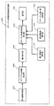
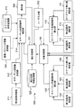
- FIG. 1 is a block diagram showing a functional configuration of a catheter tip rotation angle measuring device in the first embodiment
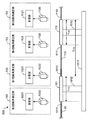
- FIG. 2 is a diagram illustrating a configuration of the movement restriction unit in the first embodiment
- FIG. 3 is a diagram illustrating an example of the first rotation angle measurement unit and the second rotation angle measurement unit in the first embodiment.
- FIG. 4 is a diagram illustrating regions measured by the first rotation angle measurement unit and the second rotation angle measurement unit in the first embodiment.
- FIG. 5 is a diagram showing the correspondence between line sensors and pixels.
- FIG. 6 is an explanatory diagram showing the relationship between the cross section of the catheter, the imaging unit, and the pixels, FIG.
- FIG. 7 is a cross-sectional view showing the relationship between the rotary encoder and the catheter.
- FIG. 8 is an explanatory diagram showing the configuration of the catheter insertion length measurement unit in the first embodiment
- FIG. 9 is an overall view of a catheter having a curved portion
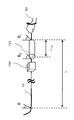
- FIG. 10 is a diagram illustrating a relationship between the first rotation angle, the second rotation angle, the catheter insertion length, the length of the movement restricting portion, and the rotation angle of the catheter tip in the first embodiment
- FIG. 11A is a diagram illustrating a state in which an example of the rotation angle of the distal end of the catheter presented to the user in the first embodiment is displayed on a display;
- FIG. 11B is a diagram showing a state in which an example of the rotation angle of the distal end of the catheter presented to the user in the first embodiment is displayed on the display together with the display “correcting”;
- FIG. 12 is a flowchart showing an example of the processing operation of the surgeon's catheterization in the first embodiment.
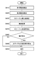
- FIG. 13 is a flowchart illustrating an example of a processing operation of the catheter tip rotation angle measuring device according to the first embodiment.
- FIG. 14 is a block diagram showing a functional configuration of the catheter tip rotation angle measuring device in the second embodiment,
- FIG. 15 is a schematic diagram illustrating a functional configuration of the X-ray imaging apparatus according to the second embodiment.
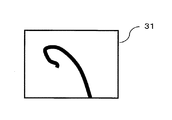
- FIG. 16 is a diagram illustrating an example of an X-ray image captured by the X-ray imaging apparatus according to the second embodiment.
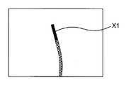
- FIG. 17 is a diagram illustrating an example of the distal end of the catheter extracted from the catheter distal end extraction unit in the second embodiment.
- FIG. 18 is an explanatory diagram illustrating an example of a processing operation of the operation detection unit according to the second embodiment.
- FIG. 19 is a flowchart showing an example of the processing operation of the catheter tip rotation angle measuring device according to the second embodiment.
- FIG. 20 is a block diagram showing a functional configuration of the catheter tip rotation angle measuring device in the third embodiment
- FIG. 21 is an explanatory diagram showing an example of a method for determining the rotation axis of the catheter in the third embodiment, FIG.
- FIG. 22 is a diagram illustrating an example of a three-dimensional shape of the catheter restored from the catheter rotation axis determination unit in the third embodiment.
- FIG. 23 is a block diagram showing a functional configuration of the catheter tip rotation angle correction unit in the third embodiment
- FIG. 24 is a diagram showing a table showing the relationship between the calibration image and the rotation angle of the catheter tip in the third embodiment
- FIG. 25 is an explanatory diagram showing a comparison between an X-ray image and a calibration image in the third embodiment.
- FIG. 26 is an explanatory diagram showing a method of calculating an epipolar line when determining the rotation axis of the catheter in the third embodiment
- FIG. 27 is a flowchart showing an example of the processing operation of the catheter tip rotation angle measuring device according to the third embodiment.
- FIG. 23 is a block diagram showing a functional configuration of the catheter tip rotation angle correction unit in the third embodiment
- FIG. 24 is a diagram showing a table showing the relationship between the calibration image and the rotation angle of the catheter tip in the third
- FIG. 28 is a flowchart showing an example of the processing operation of the catheter tip rotation angle correction unit in the third embodiment.
- FIG. 29 is an explanatory view showing an example of a guide wire inserted prior to the catheter in the modification of the first embodiment
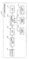
- FIG. 30 is a block diagram when automatic determination of stop of the tip rotation angle calculation is performed in the catheter tip rotation angle measuring device in the first modification example
- FIG. 31A is a diagram illustrating an example of an X-ray imaging image of a distal state of a catheter (or guide wire);
- FIG. 31B is a diagram showing an example of an X-ray imaging image of the distal end state of the catheter (or guide wire);
- FIG. 31C is a diagram illustrating an example of an X-ray imaging image of the distal end state of the catheter (or guide wire);
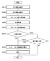
- FIG. 32 is a flowchart of the operation of the catheter tip rotation angle measuring device in the first modification
- FIG. 33 is a block diagram of the catheter tip rotation angle measuring device in the second modification
- FIG. 34 is a block diagram of the catheter tip rotation angle measuring device in the second modification
- FIG. 35 is a flowchart of the operation of the catheter tip rotation angle measuring device in the second modification
- FIG. 36 is a block diagram of a catheter tip rotation angle measuring device in a third modification.
- the operator performs an operation of adjusting the tip of the catheter or the tip of the guide wire to the branch direction of the target blood vessel or the like.
- the operator needs to accurately grasp the orientation of the distal end of the catheter or the like.
- the X-ray fluoroscopic image becomes a two-dimensional image, so it is difficult to grasp the direction of the distal end of the catheter or the like, particularly the depth direction.
- drawbacks That is, it is difficult for the operator to know whether the tip of the catheter or the like is in the front direction or the rear direction of the monitor, which may hinder the smooth operation of the catheter or the like.
- a method for X-ray imaging of a catheter or the like from two directions using an X-ray fluoroscopy device called a biplane type having two sets of an X-ray generator and an X-ray detector.
- X-ray imaging by the biplane type is usually performed with an angle difference of 90 degrees, while observing two X-ray fluoroscopic images with an angle difference of 90 degrees alternately, It is a great burden on the operator to instantly and intuitively grasp the shape of the three-dimensional catheter tip while taking into account the imaging angles of the X-ray generator and the X-ray detector.
- Patent Document 1 and Patent Document 2 have been proposed as conventional methods for detecting the direction of the distal end of the catheter.
- Patent Document 1 discloses a method of measuring the rotation angle of a catheter at the operator's hand using a rotary encoder or the like in an apparatus for simulating the three-dimensional movement of the catheter.
- the catheter may be twisted.
- the rotation angle of the catheter at the operator's hand and the rotation angle of the distal end of the catheter do not match. Therefore, in the method of Patent Document 1, when the catheter is twisted, the direction of the distal end of the catheter cannot be accurately detected.
- Patent Document 2 discloses a method for correcting rotation of the axis of the monitor display image due to twisting of the electronic endoscope by mounting a rotation detection sensor at the tip of the electronic endoscope in the electronic endoscope system. ing.
- the rotation detection sensor is attached to the distal end of the catheter to be inserted into a blood vessel having a diameter of several millimeters, there is a risk of damaging the blood vessel when the rotation detection sensor contacts the blood vessel during the catheter operation.
- the present invention solves the above-described conventional problems, and an object thereof is to provide an apparatus for measuring a rotation angle of a catheter tip in which twist is generated without attaching a rotation detection sensor to the tip of the catheter. .
- a catheter tip rotation angle measuring device is a device for measuring the rotation angle of the tip of a catheter inserted into a living body tube, and has a cylindrical shape penetrating from a first hole to a second hole.
- a movement restricting portion that restricts movement of the catheter in the insertion direction by passing the catheter from the first hole to the second hole, and a rotation angle of the catheter in the first hole.
- a first rotation angle measurement unit that measures a first rotation angle
- a second rotation angle measurement unit that measures a second rotation angle that is the rotation angle of the catheter in the second hole, and the first hole
- a catheter insertion length measuring unit for measuring a catheter insertion length which is a length from the second hole to the distal end portion of the catheter; a first rotation angle measured by the first rotation angle measuring unit; and a second rotation. Measured from the angle measurement unit The rotation angle of the tip of the catheter is calculated using the angle difference from the two rotation angles, the catheter insertion length measured by the catheter insertion length measurement unit, and the distance between the first hole and the second hole.
- a catheter tip rotation angle measuring unit is used to measure a first rotation angle
- a second rotation angle measurement unit measures a second rotation angle that is the rotation angle of the catheter in the second hole
- a catheter tip rotation angle measuring unit for measuring a catheter insertion length which is a length from the second hole to the distal end portion of the catheter.
- the rotation angle of the catheter tip can be measured without mounting a rotation detection sensor or the like on the tip of the catheter. Therefore, since there is no need to attach a rotation detection sensor or the like to the distal end of the catheter, it is possible to reduce the possibility of damaging the blood vessel in the catheter operation that requires a delicate and delicate operation.
- the catheter tip rotation angle measuring device may further include a presentation unit that presents the rotation angle of the catheter tip calculated by the catheter tip rotation angle calculation unit to the user.
- the measured rotation angle of the distal end of the catheter can be presented to the user. Therefore, the surgeon can accurately grasp the direction of the distal end of the catheter from the measured rotation angle of the distal end of the catheter. Thereby, the operator can easily adjust the distal end of the catheter to the branching direction of the target blood vessel or the like at the branching portion of the blood vessel, and can perform a smooth catheter operation.
- the operation time is shortened by smooth catheter operation, the irradiation time of X-rays irradiated to the patient is shortened. Therefore, the amount of exposure caused by X-ray irradiation to the patient can be reduced.
- the catheter tip rotation angle calculation unit sets the first rotation angle measured by the first rotation angle measurement unit as ⁇ 1 and the second rotation angle measured by the second rotation angle measurement unit as ⁇ 2.
- the catheter tip rotation angle calculation unit calculates the difference between the first rotation angle and the rotation angle of the catheter tip ( ⁇ 1 ) and the first rotation angle.
- the relationship between the rotation angle and the angle difference ( ⁇ 1 ⁇ 2 ) between the second rotation angle is related to the catheter insertion length (L) and the distance (L 12 ) between the first hole and the second hole.
- the proportionality can be used to measure the rotation angle of the catheter tip.
- the catheter tip rotation angle measuring device further includes a first image obtaining unit that obtains an X-ray image captured by an X-ray imaging device that captures an area including the distal end portion of the catheter inserted into a living body tube. Detecting a distal end portion of the catheter from the X-ray image acquired from the first image acquiring portion, and an operation of the distal end portion of the catheter extracted from the distal end portion extracting portion of the catheter.
- the catheter tip rotation angle calculator calculates the rotation angle of the catheter tip when the motion detector detects a motion, and the motion detector does not detect a motion. In this case, the rotation angle of the distal end of the catheter may not be calculated.
- the catheter tip rotation angle measuring device is further provided with a plurality of imaging parameter information acquisition units that acquire imaging parameter information that is information related to imaging conditions and postures of the respective X-ray imaging devices at the time of imaging.
- a second image acquisition unit that acquires a plurality of X-ray images including the distal end portion of the catheter imaged by the X-ray imaging apparatus, and a plurality of X-ray images acquired from the second image acquisition unit in each X-ray image Extracting the straight line portion of the catheter, using the extracted straight line portion of the catheter and the imaging parameter information when each X-ray image acquired from the imaging parameter information acquisition unit is captured, Catheter rotation which is a rotation axis with respect to the insertion direction of the catheter from the restored three-dimensional shape of the catheter.
- a catheter rotation axis determination unit for determining a plurality of types of catheters, a catheter shape storage unit for storing the shape of the catheter tip for each rotation angle of the catheter tip, and a catheter tip rotation angle correction unit
- the catheter tip rotation angle correction unit receives the first X-ray image from the plurality of X-ray images from the second image acquisition unit, and the catheter tip rotation angle calculation unit and the catheter tip rotation angle and the first X-ray image from the catheter tip rotation angle calculation unit.
- the catheter A plurality of the shape of the distal end of the catheter, and a calibration image generating unit that generates a plurality of calibration images in which the acquired shape of the distal end of the catheter and the rotation angle are associated with each other, and the acquired from the acquiring unit
- a comparison unit that compares the first X-ray image and a plurality of calibration images generated by the calibration image generation unit, and determines a calibration image having the highest degree of similarity with the first X-ray image;
- a rotation angle determination unit that determines the rotation angle corresponding to the calibration image determined by the comparison unit as a rotation angle of the distal end of the catheter; and the presentation unit is determined by the rotation angle determination unit
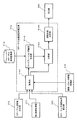
- FIG. 1 shows a functional configuration of a catheter tip rotation angle measuring apparatus 100 according to the first embodiment.
- the catheter tip rotation angle measuring device 100 includes a first rotation angle measurement unit 102, a second rotation angle measurement unit 103, a catheter insertion length measurement unit 104, a catheter tip rotation angle calculation unit 105, Have Moreover, it has the movement control part 101 which is not shown in figure. Below, each component which the catheter tip rotation angle measuring apparatus 100 has is demonstrated.
- the movement restricting portion 101 has a cylindrical shape penetrating from the first hole 1010 to the second hole 1011 and moves the catheter 10 by passing the catheter 10 from the first hole 1010 to the second hole 1011. Is regulated in the insertion direction.
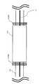
- FIG. 2 shows an example of an outline of the movement restriction unit 101.
- the movement restricting portion 101 has a cylindrical shape penetrating from the first hole 1010 to the second hole 1011.
- the first hole 1010 is the rear end of the movement restricting portion 101 when viewed from the insertion direction
- the second hole 1011 is the front end of the movement restricting portion 101 when viewed from the insertion direction. That is, the first hole 1010 is a hole on the operator side, and the second hole 1011 is a hole on the patient side.
- the movement of the catheter 10 is restricted in the insertion direction.
- the insertion direction includes rotation around the axial direction in addition to the axial direction of the catheter 10. That is, that the movement of the catheter 10 is restricted in the insertion direction means that the catheter 10 cannot move in the radial direction orthogonal to the axial direction of the catheter 10.
- the first hole 1010 and the second hole 1011 have a size that allows the catheter 10 to pass therethrough and are larger than the diameter of the catheter 10 by a predetermined size.
- the first hole 1010 and the second hole 1011 are approximately the same size as the diameter of the catheter 10, and there is almost no gap in the radial direction perpendicular to the axial direction of the catheter 10 when the catheter 10 is inserted. .
- the size of the first hole 1010 and the second hole 1011 is, for example, about 1 to 3 mm larger than the diameter of the catheter 10.
- the sizes of the first hole 1010 and the second hole 1011 may differ depending on the diameter or type of the catheter 10.
- the first hole 1010 and the second hole 1011 are about 3 mm larger than the diameter of the catheter 10 if the catheter 10 is thicker than a normal catheter, and if the catheter 10 is thinner than a normal catheter, It may be about 1 mm larger than the diameter of the catheter 10.
- the cylindrical inner surface has little frictional resistance. Therefore, the catheter operation can be performed smoothly, and the twist of the catheter 10 can be prevented from occurring inside the movement restricting portion 101.
- a distance L 12 from the first hole 1010 to the second hole 1011 is equal to the length of the movement restricting portion 101.
- the length of the movement restricting portion 101 is about 10 cm.
- the movement restricting unit 101 may be fixed to the base 1013 by the legs 1012. By fixing the movement restricting portion 101 to the base 1013, a first rotation angle and a second rotation angle described later can be measured with high accuracy.
- the first rotation angle measurement unit 102 measures the first rotation angle ⁇ 1 that is the rotation angle of the catheter 10 in the first hole 1010.
- the measurement location of the first rotation angle measurement unit 102 is within a predetermined range including the position of the first hole 1010.
- the measurement location of the first rotation angle measurement unit 102 is preferably as close to the first hole 1010 as possible, for example, within a range of 3 mm from the first hole.
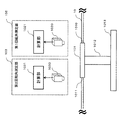
- FIG. 3 shows an example of an outline of the first rotation angle measurement unit 102.
- the first rotation angle measurement unit 102 includes an imaging unit 1020 and a calculation unit 1021.
- FIG. 4 shows the movement restricting portion 101 as viewed from above.
- a line 11 is drawn in advance on the surface of the catheter 10 in a direction parallel to the central axis of the catheter 10.
- the imaging unit 1020 captures the range 1022.
- the calculation unit 1021 extracts the position of the line 11 from the image captured by the imaging unit 1020, and acquires the rotation angle in the range 1022 from the position displacement of the line 11 with respect to the center of the catheter 10.
- a specific method in which the first rotation angle measurement unit 102 measures the first rotation angle will be described.
- the photographing unit 1020 is a camera, for example, and the calculation unit 1021 is a CPU of a PC, for example.
- the imaging unit 1020 starts imaging upon receiving a detection start input from the operator.
- the imaging unit 1020 continues to image the catheter 10 at regular intervals.
- the calculation unit 1021 extracts the position of the line 11 in each image for a plurality of captured images. For example, when the catheter 10 is white and the line 11 is black, the black position is extracted.
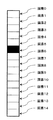
- FIG. 5 shows a photographed image when the photographing unit 1020 is a line sensor including 15 pixels.
- the imaging unit 1020 is arranged so that the entire width of the catheter 10 (in the direction perpendicular to the axial direction) is imaged by these 15 pixels.
- the calculation unit 1021 performs a process of acquiring “5” that is the number of the pixel 5.
- the calculation unit 1021 determines whether the brightness of each pixel is equal to or less than a threshold value.
- the brightness of the pixel takes a value from 0 to 255, where 0 is the darkest and 255 is the brightest, and the threshold is 50.
- the number of the pixel whose brightness is equal to or less than the threshold value is set as the position of the line 11.
- FIG. 6 shows the relationship between the position of the line 11 and the rotation angle of the catheter.
- a circle on the right side of FIG. 6 is a cross-sectional view of the catheter 10.
- the left side of FIG. 6 shows the photographing unit 1020.
- the photographing unit 1020 has an element for photographing pixels 0 to 14, and an enlarged view of this is shown in the middle of FIG.
- the boundary of the range captured by each pixel is indicated by a dotted line.
- the pixel 7 is a pixel in which the center of the catheter range (here, pixel 0 to pixel 14) in the image photographed by the photographing unit 1020 is photographed.
- the pixel 7 is referred to as a center pixel 1022.
- a surface portion of the catheter 10 photographed by the center pixel 1022 is set as a center position 12.
- Pixel 5 is the position of line 11 drawn on the surface of catheter 10.
- the pixel 5 is referred to as a line position pixel 1023.
- the angle ⁇ 1 is the rotation angle of the line 11 from the center position 12, that is, the first rotation angle that is the rotation angle of the catheter 10 in the first hole 1010.
- the angle ⁇ 1 is expressed by the relational expression (1) from the definition of the trigonometric function.
- ⁇ 1 arcsin (h / r) (2)
- the first rotation angle measurement unit 102 does not need to be configured by the photographing unit 1020 and the calculation unit 1021, and may be configured by a rotary encoder or the like.
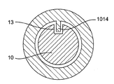
- FIG. 7 the block diagram of the 1st rotation angle measurement part 102 at the time of measuring the rotation angle of the catheter 10 using a rotary encoder is shown.
- FIG. 7 shows a state seen from the insertion direction of the catheter 10. Since the groove portion 13 provided in advance in the catheter 10 and the protrusion portion 1014 provided in advance in the movement restricting portion 101 are engaged with each other, the rotation of the catheter 10 and the rotation of the rotary encoder are synchronized. Ten rotation angles can be measured.
- a rotary encoder an absolute value encoder or the like (Soichi Ogawa et al., Basic Robotics, 1998, p98, Tokyo Denki University Press) can be used.
- the second rotation angle measurement unit 103 measures a second rotation angle ⁇ 2 that is the rotation angle of the catheter 10 in the second hole 1011.
- the second rotation angle measurement unit 103 can be realized by the same configuration as the first rotation angle measurement unit 102.
- FIG. 3 shows a schematic example of the second rotation angle measurement unit 103.
- the second rotation angle measurement unit 103 includes an imaging unit 1030 and a calculation unit 1031.
- a specific method in which the second rotation angle measurement unit 103 measures the second rotation angle ⁇ 2 using the imaging unit 1030 and the calculation unit 1031 is that the first rotation angle measurement unit 102 uses the first rotation angle ⁇ . This is the same as the method of measuring 1 .
- the second rotation angle measurement unit 103 does not need to be configured by the imaging unit 1030 and the calculation unit 1031, and may be configured by a rotary encoder or the like.
- a specific method in which the second rotation angle measurement unit 103 measures the second rotation angle ⁇ 2 using a rotary encoder is a method in which the first rotation angle measurement unit 102 measures the first rotation angle ⁇ 1. It is the same.
- the catheter insertion length measurement unit 104 measures the catheter insertion length L, which is the length from the first hole 1010 or the second hole 1011 to the distal end portion of the catheter 10.
- FIG. 8 shows an example of the outline of the catheter insertion length measurement unit 104.
- FIG. 8 shows a case where the length from the first hole 1010 to the distal end portion 15 of the catheter 10 is the catheter insertion length L.
- the catheter insertion length measurement unit 104 is configured to change, for example, a roller 1040 that interlocks with advancement and retraction of the catheter 10 by pressing the catheter 10, an encoder 1041 that measures the amount of rotation of the roller 1040, and a rotation angle value of the encoder 1041.
- the calculation unit 1042 calculates the insertion length from the quantity.
- the calculation unit 1042 sets the initial value “0” before starting the operation of the catheter 10.
- the catheter 10 is passed through the roller 1040, and from that time, the calculation unit 1042 starts calculating the insertion length of the catheter 10 and calculates until the operation of the catheter 10 ends. to continue.
- the catheter insertion length measurement unit 104 can continue to measure the insertion length L of the catheter 10 in real time during the operation of the catheter 10.
- the distal end of the catheter 10 has a curved portion 15.
- the bending portion 15 (hereinafter, also referred to as “catheter distal end portion 15”) is different from other catheters 10 in material and the like, and is easily bent.
- the catheter insertion length measurement unit 104 measures the distance from the first hole 1010 to the bending portion 15 as the catheter insertion length L. That is, the length not including the distal end portion 15 of the catheter corresponds to the catheter insertion length L. By not including the distal end portion 15 of the catheter in the catheter insertion length L, the rotation angle ⁇ of the distal end of the catheter 10 can be calculated more accurately.
- the catheter insertion length measuring unit 104 does not necessarily need to have a length that does not include the distal end portion 15 of the catheter as the catheter insertion length L, and measures the length that includes the distal end portion 15 of the catheter as the catheter insertion length L. Also good.
- the catheter insertion length measuring unit 104 may be configured to take an image of a scale relating to the insertion position described on the surface of the catheter 10 by an imaging means such as a camera and calculate the insertion length based on the value of the scale. .
- the catheter insertion length measurement unit 104 does not need to be provided independently of the movement restricting unit 101 and may be provided in the movement restricting unit 101.
- the catheter insertion length measurement unit 104 may set the length from the second hole 1011 to the distal end portion of the catheter 10 as the catheter insertion length L.
- the catheter tip rotation angle calculation unit 105 calculates an angle difference ( ⁇ between the first rotation angle ⁇ 1 measured by the first rotation angle measurement unit 102 and the second rotation angle ⁇ 2 measured by the second rotation angle measurement unit 103. 1 - [theta] 2), the catheter insertion length L measured from the catheter insertion length measurement unit 104, and the first hole 1010 with a distance L 12 between the second hole 1011, the rotation angle ⁇ of the tip of the catheter calculate.
- the catheter tip rotation angle calculation unit 105 receives the first rotation angle ⁇ 1 from the first rotation angle measurement unit 102, the second rotation angle ⁇ 2 from the second rotation angle measurement unit 103, and the catheter insertion from the catheter insertion length measurement unit 104. Each of the lengths L is acquired. The catheter tip rotation angle calculation unit 105 calculates an angle difference ( ⁇ 1 ⁇ 2 ) between the acquired first rotation angle ⁇ 1 and second rotation angle ⁇ 2 . In addition, the operator sets in advance the distance L 12 between the first hole 1010 and the second hole 1011 in the catheter tip rotation angle calculation unit 105 before starting the operation of the catheter 10.
- FIG. 10 shows the relationship between parameters when the first hole 1010 is on the operator side.
- the first hole 1010 is on the operator side and the catheter insertion length L is the length from the first hole 1010 to the distal end portion 15 of the catheter 10 will be described.
- the relationship of the expression (3) is established between the parameters.
- Equation (3) represents the overall twist angle ( ⁇ 1 ⁇ ) of the catheter 10 and the first The relationship between the twist angle ( ⁇ 1 ⁇ 2 ) between the first hole 1010 and the second hole 1011 is proportional to the relationship between the catheter insertion length L and the distance L 12 between the first hole 1010 and the second hole 1011. Represents that. Therefore, the rotation angle ⁇ of the catheter tip can be calculated from the equation (4).
- the catheter insertion length L is the second hole.
- the rotation angle ⁇ of the catheter tip when the length from 1011 to the tip 15 of the catheter 10 can be calculated from the equation (7).
- the presentation unit 106 presents the rotation angle ⁇ of the distal end of the catheter 10 calculated by the catheter tip rotation angle calculation unit 105 to the user.
- the presentation unit 106 is not an essential component of the catheter tip rotation angle measuring device 100, but is a user by presenting the rotation angle ⁇ of the tip of the catheter 10 calculated by the catheter tip rotation angle calculation unit 105 to the user. Helps the operator operate the catheter.
- the presentation unit 106 displays, for example, a numerical value on the display of the rotation angle ⁇ of the distal end of the catheter 10 calculated by the catheter tip rotation angle calculation unit 105. Moreover, you may display in three dimensions using CG etc. of the catheter 10 which reflected the rotation angle (theta) of the front-end
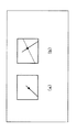
- FIG. 11A shows an example in which the rotation angle ⁇ of the distal end of the catheter 10 is displayed at the lower right of the display using an arrow.
- Step S100> The operator sets initial values of the first rotation angle measurement unit 102, the second rotation angle measurement unit 103, and the catheter insertion length measurement unit 104 to 0 as advance preparations for performing the treatment. In addition, the operator inputs the distance L 12 between the first hole 1010 and the second hole 1011 to the catheter tip rotation angle calculation unit 105. Then, the operator selects the catheter 10 suitable for the diagnosis site or the treatment site, passes the selected catheter 10 from the first hole 1010 to the second hole 1011 of the movement restricting portion 101, and further measures the catheter insertion length. Pass through part 104.
- “0” in the first rotation angle measurement unit 102 and the second rotation angle measurement unit 103 may be, for example, 0 in the direction orthogonal to the insertion direction of the catheter 10 and from the floor to the ceiling.
- the initial value of the 1st rotation angle measurement part 102, the 2nd rotation angle measurement part 103, and the catheter insertion length measurement part 104 was set to 0, it may not be 0.
- Each value may be measured from the numerical value at the start of measurement and the numerical value during measurement.
- ⁇ Step S200> The surgeon inserts the catheter 10 into the patient.
- Step S300> The surgeon operates the catheter 10 while monitoring the X-ray image of the catheter 10 projected on the display, and inserts the catheter 10 to the diagnosis site or treatment site.
- Step S400> When the operator wants to recognize the direction of the distal end of the catheter 10, the operator performs an input for starting measurement of the rotation angle ⁇ of the distal end of the catheter 10.
- Examples of the device that accepts an input include a keyboard and a push button.
- the catheter tip rotation angle measuring apparatus 100 executes steps S410 to S450 described later, and presents the rotation angle of the tip of the catheter 10 to the operator.
- the measurement of the rotation angle of the distal end of the catheter 10 is not limited to being started after waiting for input, and may be measured at a predetermined time interval.
- ⁇ Step S500> The surgeon continues to operate the catheter 10 with reference to the rotation angle ⁇ of the tip of the catheter presented by the presentation unit 106.
- Step S600> The surgeon executes step S300 when the diagnosis or treatment is not completed, and executes step S700 when the diagnosis or treatment is completed.
- Step S700> When completing the diagnosis or treatment, the operator removes the catheter 10 from the patient and finishes the treatment.
- the method of measuring the rotation angle ⁇ of the distal end of the catheter 10 is simply to measure the rotation angle ⁇ of the distal end of the catheter 10. That is, the method does not include the operator performing the catheter operation in step S500 based on the rotation angle ⁇ of the distal end of the catheter measured in step S400. Therefore, the method for measuring the rotation angle ⁇ of the distal end of the catheter 10 is not a method for performing a surgical process on the human body and does not correspond to a method for operating a human.
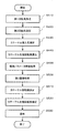
- FIG. 13 shows a flow of processing operations of the catheter tip rotation angle measuring apparatus 100 in the first embodiment.
- the first rotation angle measurement unit 102 measures a first rotation angle that is the rotation angle of the catheter 10 in the first hole 1010. Specific methods of the first rotation angle theta 1 of the measurement is as described above. Further, the first rotation angle measurement unit 102 outputs the measured first rotation angle ⁇ 1 to the catheter tip rotation angle calculation unit 105.
- the second rotation angle measurement unit 103 measures a second rotation angle that is the rotation angle of the catheter 10 in the second hole 1011. Specific method of the second rotation angle theta 2 of the measurement are as described above. Further, the second rotation angle measurement unit 103 outputs the measured second rotation angle ⁇ 2 to the catheter tip rotation angle calculation unit 105.
- the catheter insertion length measurement unit 104 measures the catheter insertion length, which is the length from the first hole 1010 to the distal end portion 15 of the catheter 10.
- the specific method for measuring the catheter insertion length L is as described above. Further, the catheter insertion length measurement unit 104 outputs the measured catheter insertion length L to the catheter tip rotation angle calculation unit 105.
- the catheter tip rotation angle calculation unit 105 calculates an angle difference ( ⁇ between the first rotation angle ⁇ 1 measured by the first rotation angle measurement unit 102 and the second rotation angle ⁇ 2 measured by the second rotation angle measurement unit 103. 1 - [theta] 2), the catheter insertion length L measured from the catheter insertion length measurement unit 104, and the first hole 1010 with a distance L 12 between the second hole 1011, the rotation angle ⁇ of the tip of the catheter calculate.
- the catheter tip rotation angle calculation unit 105 calculates the first rotation angle ⁇ 1 measured in step S410, the second rotation angle ⁇ 2 measured in step S420, and the catheter insertion length L measured in step S430. Get each.
- the catheter tip rotation angle calculation unit 105 an angular difference from the first rotation angle theta 1 and the second rotation angle theta 2 which the acquired first rotation angle theta 1 and the second rotation angle theta 2 (theta 1 - ⁇ 2 ) is calculated.
- the catheter tip rotation angle calculator 105 calculates the angle difference ( ⁇ 1 ⁇ 2 ) between the calculated first rotation angle ⁇ 1 and the second rotation angle ⁇ 2 , the acquired catheter insertion length L, and step S100. in using the first hole 1010, which is set a distance L 12 between the second hole 1011, (4) from equation to calculate the rotation angle ⁇ of the tip of the catheter 10.
- the catheter tip rotation angle calculation unit 105 outputs the calculated rotation angle ⁇ of the tip of the catheter 10 to the presentation unit 106.
- Step S450> The presentation unit 106 acquires the rotation angle ⁇ of the distal end of the catheter 10 calculated in step S440, and presents the acquired rotation angle ⁇ of the distal end of the catheter 10 to the user.
- the specific method of presentation by the presentation unit 106 is as described above.
- ⁇ Effect> As described above, according to the catheter tip rotation angle measuring device 100 in the first embodiment, when the catheter 10 is twisted uniformly, the catheter 10 is not attached to the tip of the catheter 10 without attaching a rotation detection sensor or the like. The rotation angle of the tip of 10 can be measured. Thereby, since there is no need to attach a rotation detection sensor or the like to the distal end of the catheter 10, the possibility of damaging a blood vessel in the operation of the catheter 10 requiring a delicate and delicate operation can be reduced.
- the operator can accurately grasp the orientation of the distal end of the catheter 10 from the measured rotation angle ⁇ of the distal end of the catheter 10. I can do it.
- the operator can easily adjust the distal end of the catheter 10 in the branching direction of the target blood vessel or the like at the branching portion of the blood vessel, and can perform a smooth catheter operation.
- the operation time is shortened by smooth catheter operation, the irradiation time of X-rays irradiated to the patient is shortened. Therefore, the amount of exposure caused by X-ray irradiation to the patient can be reduced.
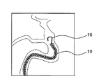
- FIG. 29 shows an example of an image when the guide wire 16 is advanced into the catheter 10 through the guide wire 16 through the lumen of the catheter 10 inserted into the blood vessel.
- the guide wire 16 is preceded before insertion of the catheter 10 to make it difficult to damage the blood vessel wall and to smoothly carry the catheter 10 to the lesioned part.
- the surface of the lumen of the catheter 10 has a small frictional resistance, or the surgeon injects a small amount of water into the lumen of the catheter 10 during treatment to facilitate passage through the guide wire. Therefore, when the guide wire 16 is twisted, a load is applied to the rotation of the distal end of the guide wire 16, and the twist of the guide wire 16 caused by the twist is uniformly generated in the lumen of the catheter 10. It is done.
- the parent catheter makes it easy to guide the latter child catheter, the thickness is about 2 mm, and the child catheter is for actually treating the lesioned part, and the thickness is 1 mm.
- the parent catheter makes it easy to guide the latter child catheter, the thickness is about 2 mm, and the child catheter is for actually treating the lesioned part, and the thickness is 1 mm.
- the child catheter By passing the child catheter through the lumen of the parent catheter inserted into the blood vessel, the child catheter can be smoothly carried to the lesion, and the child catheter is used to treat the lesion, such as expanding the narrowed blood vessel with a balloon. be able to. Even in this case, when twisting occurs in the child catheter, a load is applied to the rotation of the distal end of the child catheter, and it is considered that the twisting of the child catheter is caused uniformly in the lumen of the parent catheter. It is done.
- the catheter tip rotation angle measuring apparatus 100 can be used particularly effectively in a guide wire inserted prior to the catheter or a child catheter inserted beyond the parent catheter. .
- the catheter tip rotation angle measuring device 200 detects the movement of the tip 15 of the catheter 10 and, when motion is detected, calculates the rotation angle ⁇ of the tip of the catheter 10 and no motion is detected. In this case, the point of rotation angle ⁇ of the catheter 10 is not calculated, which is different from the catheter tip rotation angle measuring apparatus 100 of the first embodiment. Below, it demonstrates focusing on a different point from 1st Embodiment.
- FIG. 14 shows a functional configuration of the catheter tip rotation angle measuring apparatus 200 in the second embodiment.
- the same components as those in FIG. 1 are denoted by the same reference numerals, and description thereof will be omitted as appropriate.
- the catheter tip rotation angle measuring device 200 includes a first rotation angle measurement unit 102, a second rotation angle measurement unit 103, a catheter insertion length measurement unit 104, a catheter tip rotation angle calculation unit 205, , A presentation unit 106, a first image acquisition unit 207, a catheter tip portion extraction unit 208, and a motion detection unit 209.
- a first rotation angle measurement unit 102 a second rotation angle measurement unit 103
- a catheter insertion length measurement unit 104 the catheter tip rotation angle calculation unit 205
- a presentation unit 106 a first image acquisition unit 207
- motion detection unit 209 a motion detection unit
- the first image acquisition unit 207 acquires the X-ray image 30 captured by the X-ray imaging apparatus 20 that captures an area including the distal end portion of the catheter 10 inserted into the living body tube.
- FIG. 15 shows the configuration of the first image acquisition unit 207 and the X-ray imaging apparatus 20.
- the X-ray imaging apparatus 20 is an apparatus that acquires an X-ray image captured by irradiating X-rays to an imaging target region of a patient or a blood vessel image captured when a contrast agent is injected.
- the X-ray imaging apparatus 20 is an apparatus that acquires an X-ray image captured by irradiating X-rays to an imaging target region of a patient or a blood vessel image captured when a contrast agent is injected.
- it is called an X-ray angiography apparatus or angiography.
- the X-ray imaging apparatus 20 includes an X-ray generation unit 21, an X-ray detection unit 22, a mechanism unit 23, a mechanism control unit 24, an arm 26, and a database 25.
- the X-ray generation unit 21 includes an X-ray tube that generates X-rays using a high voltage and an X-ray diaphragm that controls an irradiation field by shielding a part of the X-rays.
- the patient 28 is irradiated with X-rays.
- the X-ray detection unit 22 receives X-rays transmitted through the patient 28, records image information, and outputs the recorded image information. For example, an X-ray sensing layer is disposed, and the X-rays are converted into digital data.
- the X-ray detection unit 22 outputs image information indicating the irradiated X-ray image 30 to the database 25.
- the mechanism unit 23 moves the arm 26 and the bed 27 based on the instruction of the mechanism control unit 24 that has received the operator's operation instruction.
- the first image acquisition unit 207 reads an X-ray image or an X-ray image stored in the database 25 and outputs it to the catheter tip portion extraction unit 208.
- FIG. 16 shows an example of the X-ray image 30 of the catheter 10 acquired by the first image acquisition unit 207.
- the distal end portion 15 of the catheter is a portion including the bending portion 15 shown in FIG. 9, for example, a portion from the distal end of the catheter 10 to 1 to 2 cm in addition to the length La of the bending portion 15.
- the distal end portion 15 of the catheter may be the same portion as the bending portion 15.
- the catheter tip extraction unit 208 extracts the catheter tip 15 from the X-ray image 30 acquired from the first image acquisition unit 207.
- the catheter tip portion extraction unit 208 compares the acquired X-ray image 30 with the X-ray image of the previous frame, and extracts only the portion where the lightness is changed for each pixel. Thereby, only when the catheter 10 moves, the distal end portion 15 of the catheter can be extracted. For example, when the brightness of a pixel takes a value of “0 to 255”, “0” is the darkest and “255” is the brightest, the pixel of the current frame is subtracted from the pixel of the previous frame of the X-ray image 30.
- FIG. 17 shows an image of the distal end 15 of the catheter 10 extracted by the catheter distal end extracting unit 208.
- the catheter tip portion extraction unit 208 may compare the frame with a certain time before (for example, one second before).
- the catheter distal end extraction unit 208 is not limited to the above method, and determines the linearity of the catheter 10, recognizes a portion having a low linearity value as the bending portion 15, and includes a predetermined bending portion 15 including the recognized bending portion 15. The region may be extracted as the distal end portion 15 of the catheter 10.
- the motion detection unit 209 detects the motion of the distal end portion 15 of the catheter 10 extracted by the catheter distal end portion extraction unit 208.
- the motion detection unit 209 can indirectly detect the insertion or rotation of the proximal portion by detecting the motion of the distal end portion 15 of the catheter 10.
- the hand portion is a portion including the movement restricting portion 101 and the catheter insertion length measuring portion 104.
- the motion detection unit 209 detects the motion of the distal end portion 15 when the number of pixels whose brightness has changed in the extraction of the distal end portion 15 of the catheter 10 is greater than or equal to a predetermined number of pixels. For example, the motion detection unit 209 detects the motion of the tip 15 when the brightness is “0” and the number of pixels is “10” or more. In addition, when extracting the distal end portion 15 of the catheter 10, when the distal end portion 15 of the catheter 10 does not move, the motion detection unit 209 extracts the brightness of all the pixels as “255” and detects the motion of the distal end portion 15. Not.
- FIG. 18 shows whether the distal end portion 15 of the catheter 10 is detected by the motion detection unit 209 by comparing the previous frame and the current frame.
- the motion detection unit 209 is not limited to the above method, and compares the tip portion 15 drawn from the X-ray image 30 with a marginal edge with a predetermined time interval (for example, an interval of 1 ms) to determine a predetermined value (for example, , 0.03 mm) or more may be detected, and the operation may not be detected if there is no change greater than a predetermined value.
- a predetermined time interval for example, an interval of 1 ms
- the catheter tip rotation angle calculation unit 205 calculates an angular difference ( ⁇ between the first rotation angle ⁇ 1 measured by the first rotation angle measurement unit 102 and the second rotation angle ⁇ 2 measured by the second rotation angle measurement unit 103. 1 - [theta] 2), the catheter insertion length L measured from the catheter insertion length measurement unit 104, and the first hole 1010 with a distance L 12 between the second hole 1011, the rotation angle ⁇ of the tip of the catheter calculate.
- the catheter tip rotation angle calculation unit 205 calculates the rotation angle ⁇ of the tip of the catheter 10 when the motion detection unit 209 detects motion, and when the motion detection unit 209 does not detect motion, The rotation angle ⁇ of the tip is not calculated.
- the specific calculation method of the distal end rotation angle ⁇ of the catheter 10 calculated by the catheter distal end rotation angle calculation unit 205 is the same as the calculation method of the catheter distal end rotation angle calculation unit 105 in the first embodiment.
- FIG. 19 shows a flow of processing operations of the catheter tip rotation angle measuring apparatus 200 in the second embodiment.
- the same steps as those in FIG. 13 are denoted by the same reference numerals, and description thereof will be omitted as appropriate.
- the first image acquisition unit 207 acquires the X-ray image 30 captured by the X-ray imaging apparatus 20 from the database 25.
- the specific method for acquiring the image is as described above.
- the first image acquisition unit 207 outputs the acquired X-ray image 30 to the catheter tip portion extraction unit 208.
- the catheter tip portion extraction unit 208 extracts the tip portion 15 of the catheter 10 from the X-ray image 30 acquired from the first image acquisition unit 207. First, the catheter tip extraction unit 208 acquires the X-ray image 30 acquired from step S460. Next, the catheter tip portion extraction unit 208 extracts the tip portion 15 of the catheter 10 from the acquired X-ray image 30. The specific method for extracting the tip 15 is as described above. Next, the catheter distal end extraction unit 208 outputs the extracted distal end 15 to the motion detection unit 209.
- Step S480> The motion detector 209 detects the motion of the catheter tip 15 extracted by the catheter tip extractor 208. First, the motion detection unit 209 acquires the tip 15 extracted from step S470. Next, the motion detection unit 209 detects the motion of the acquired tip portion 15. A specific method for detecting the operation of the distal end portion 15 is as described above. Next, the motion detection unit 209 executes step S440 when the motion of the tip portion 15 is detected, and executes step S450 when the motion of the tip portion 15 is not detected. That is, when the motion detection unit 209 does not detect the motion of the distal end portion 15, the presentation unit 105 continues to present the rotation angle ⁇ of the distal end of the catheter 10 currently being presented to the user.
- the catheter tip rotation angle measuring apparatus 200 in the second embodiment when the operation of the tip portion 15 of the catheter 10 is detected, the rotation angle ⁇ of the tip of the catheter 10 is measured. . Therefore, the surgeon can grasp the rotation angle ⁇ of the distal end of the catheter 10 in real time in accordance with his / her own catheter operation. Thus, the operator can easily adjust the distal end of the catheter 10 in the branching direction of the target blood vessel or the like at the branching portion of the blood vessel, and can perform a smooth catheter operation. In addition, since the operation time is shortened by smooth catheter operation, the irradiation time of X-rays irradiated to the patient is shortened. Therefore, the amount of exposure caused by X-ray irradiation to the patient can be reduced.
- the catheter tip rotation angle measuring apparatus 300 is capable of accurately measuring the rotation angle of the tip of the catheter 10 even when a part of the catheter 10 is twisted. Different from the catheter tip rotation angle measuring apparatus 100 of FIG. below, it demonstrates focusing on a different point from 1st Embodiment.
- FIG. 20 shows a functional configuration of the catheter tip rotation angle measuring apparatus 300 in the third embodiment.
- the same components as those in FIG. 1 are denoted by the same reference numerals, and description thereof will be omitted as appropriate.
- the catheter tip rotation angle measuring device 300 includes a first rotation angle measurement unit 102, a second rotation angle measurement unit 103, a catheter insertion length measurement unit 104, a catheter tip rotation angle calculation unit 305, A presentation unit 306, an imaging parameter information acquisition unit 310, a second image acquisition unit 311, a catheter rotation axis determination unit 312, a catheter shape storage unit 313, and a catheter tip rotation angle correction unit 314. Moreover, it has the movement control part 101 which is not shown in figure. Below, each component which the catheter front-end
- the imaging parameter information acquisition unit 310 acquires imaging parameter information that is information relating to imaging conditions and postures of the respective X-ray imaging devices 20 at the time of imaging.
- the imaging parameter information is an apparatus parameter (internal parameter) of the X-ray imaging apparatus 20 and a position / orientation parameter (external parameter) at the time of imaging of the X-ray imaging apparatus 20.
- the internal parameter is a parameter related to imaging of the X-ray imaging apparatus 20, and for example, shutter speed, aperture value, exposure correction value, ISO sensitivity value, white balance setting value, recording image size, and recording It is a parameter that affects image quality and other image creation.
- the external parameter is a parameter related to the position or orientation of the X-ray imaging apparatus 20 at the time of imaging. For example, when the origin and the directions of the X, Y, and Z axes are determined in space, the X-ray imaging apparatus 20 The position is represented by (x, y, z).
- the imaging parameter information acquisition unit 310 outputs the acquired imaging parameter information to the outside as a perspective projection row example.
- the perspective projection matrix will be described. Assuming that the point X in the three-dimensional space is projected onto the point m in the two-dimensional perspective image, this projection can be expressed as in equation (8) using homogeneous coordinates.
- the image point m in the equation (8) is a 3 ⁇ 1 vector
- the three-dimensional point X is a 4 ⁇ 1 vector
- the matrix P of the 3 ⁇ 4 matrix is called a perspective projection matrix or a projection matrix.
- ⁇ is a real number indicating indefiniteness of a constant multiple.
- the projection matrix P indicates a geometric relationship such as a focal length at the time of fluoroscopic image shooting, a three-dimensional rotation and a parallel movement from the three-dimensional space coordinate system to the fluoroscopic image coordinate system.
- the 2nd image acquisition part 311 images the area
- the second image acquisition unit 311 has substantially the same configuration as the first image acquisition unit 207.
- the second image acquisition unit 311 acquires a plurality of X-ray images 30 captured by a plurality of X-ray imaging devices 20 arranged at different positions.
- the plurality of X-ray imaging devices 20 arranged at different positions include, for example, two sets of an X-ray generation unit 21 and an X-ray detection unit 22, and the imaging angle difference between them is 90 degrees.
- This is a biplane type X-ray imaging apparatus capable of simultaneously capturing X-ray images.
- the different positions mean that the X-ray detection units 22 are installed at the same location and the cases where the X-ray detection units 22 are installed at opposite locations.
- the angle difference should be 5 degrees or more.
- the catheter rotation axis determination unit 312 extracts the straight line portion of the catheter 10 in each X-ray image from the plurality of X-ray images acquired from the second image acquisition unit 311, and extracts the straight line portion of the catheter 10 and the parameters Using the parameter information obtained when each X-ray image acquired from the information acquisition unit 310 is captured, the three-dimensional shape of the catheter 10 is restored. From the restored three-dimensional shape of the catheter 10, the insertion direction of the catheter 10 is restored. Determine the axis of rotation. The catheter rotation axis determination unit 312 outputs the determined rotation axis and the X-ray image acquired from the second image acquisition unit 311 to the outside.
- the catheter rotation axis determination unit 312 extracts a straight portion of the catheter 10 in each X-ray image 30 from the plurality of X-ray images acquired from the second image acquisition unit 311.
- a specific extraction method will be described using an example in which two X-ray images 30 are acquired from the second image acquisition unit 311.
- the catheter rotation axis determination unit 312 acquires two X-ray images 30 having an angle difference from the second image acquisition unit 311.
- the catheter rotation axis determination unit 312 extracts a straight portion of the catheter 10 for each of the two acquired X-ray images 30.
- the straight portion of the catheter 10 is a portion not including the bending portion 15 of the catheter 10 as shown in FIG.
- the catheter rotation axis determination unit 312 determines the linearity of the catheter 10, recognizes a portion having a predetermined linearity or more as the straight portion 14, and sets a predetermined region including the recognized straight portion 14 as a straight portion of the catheter 10. Extract.
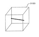
- FIG. 21 shows a schematic diagram for determining the rotation axis of the catheter 10.
- the catheter rotation axis determination unit 312 acquires a straight line image 140 and a straight line image 141 that are images obtained by extracting straight portions of the catheter 10 from the two X-ray images 30. Further, the catheter rotation axis determination unit 312 includes the X-ray generation unit 210 and the X-ray generation unit 211, the X-ray detection unit 220, and the X-ray detection unit 221 when the linear part image 140 and the linear part image 141 are acquired. Is acquired from the imaging parameter information acquisition unit 310.
- the catheter rotation axis determination unit 312 performs the three-dimensional shape restoration of the straight portion of the catheter 10 using the two straight portion images 140 and the straight portion image 141 and two sets of imaging parameter information.
- a specific method for restoring the three-dimensional shape is as follows. First, in order to extract corresponding points between two images, a Fundamental matrix indicating a geometrical relationship between the two images is calculated from the imaging parameter information using equation (9).
- FIG. 26 shows an outline of the epipolar line. As shown in FIG. 26, (a) in the figure is a point on a straight line in the straight line portion image 140, and a dotted line in (b) in the figure is an epipolar line with respect to a straight point.
- the epipolar line indicates the existence range in the straight line image 140. Therefore, the corresponding point between the straight line portion image 140 and the straight line portion image 141 can be calculated by calculating the intersection of the epipolar line and the extracted straight line. Since the projection formula like Formula (8) is established at the corresponding points between the imaging parameter information (projection matrix of each X-ray tube) and the straight line portion image 140 and the straight line portion image 141, each projection formula is expressed as a three-dimensional point. Summarizing X, it can be transformed as shown in equation (11).
- a three-dimensional point can be restored from corresponding points between the imaging parameter information (each projection matrix) and the straight line portion image 140 and the straight line portion image 141 by using the expression (12) obtained by modifying the expression (11). it can.
- M is an abbreviation of the 4 ⁇ 3 matrix on the left side of Equation (11)
- b is an abbreviation of the 4 ⁇ 1 matrix on the right side of Equation (11).
- FIG. 22 shows the restored three-dimensional straight line of the catheter 10.
- the catheter rotation axis determination unit 312 determines the rotation axis with respect to the insertion direction of the catheter 10 from the three-dimensional shape of the catheter 10 restored by the above method.
- the catheter shape storage unit 313 stores the shape of the distal end of the catheter 10 for each of the rotation angles of the distal end of the catheter 10 for a plurality of types of catheters 10.
- catheters 10 or guidewires There are many types of catheters 10 or guidewires inserted prior to them, and there are various shapes depending on the application. For example, there is a catheter called Judkins for the right coronary artery or the left coronary artery, and the tip is bent according to each anatomical position, and the shape is easy to insert.
- the catheter shape storage unit 313 stores various three-dimensional shape models corresponding to them in advance. Then, a surgeon or a radiologist who handles radiation equipment sets the type in the catheter shape storage unit 313 in advance before inserting the catheter 10 or the guide wire.
- the catheter tip rotation angle calculation unit 305 includes an angle difference ( ⁇ between the first rotation angle ⁇ 1 measured by the first rotation angle measurement unit 102 and the second rotation angle ⁇ 2 measured by the second rotation angle measurement unit 103. 1 - [theta] 2), the catheter insertion length L measured from the catheter insertion length measurement unit 104, and the first hole 1010 with a distance L 12 between the second hole 1011, the rotation angle ⁇ of the tip of the catheter calculate.
- the catheter tip rotation angle calculation unit 305 outputs the second rotation angle ⁇ 2 measured by the second rotation angle measurement unit 103 to the outside in addition to the calculated catheter tip rotation angle ⁇ .
- FIG. 23 shows a functional configuration of the catheter tip rotation angle correction unit 314.
- the catheter tip rotation angle correction unit 314 includes an acquisition unit 3141, a calibration image generation unit 3142, a comparison unit 3143, and a rotation angle determination unit 3144. Below, each component which the catheter front-end
- the acquisition unit 3141 obtains the first X-ray image from the plurality of X-ray images from the second image acquisition unit 311, and the rotation angle ⁇ and the second rotation angle ⁇ 2 of the distal end of the catheter 10 from the catheter tip rotation angle calculation unit 305.
- the catheter rotation axis determination unit 312 acquires the catheter rotation axis, and the imaging parameter information acquisition unit 310 acquires the imaging parameter information when the first X-ray image is captured.
- the calibration image generation unit 3142 receives the shape of the tip of the catheter 10 for each rotation angle from the rotation angle ⁇ of the tip of the catheter 10 acquired from the acquisition unit 3141 from the catheter shape storage unit 313 to the second rotation angle ⁇ 2. And a plurality of calibration images in which the acquired tip shape of the catheter 10 is associated with the rotation angle ⁇ a are generated.
- FIG. 24 shows an example of a calibration image. A specific method by which the calibration image generation unit 3142 generates a calibration image will be described.
- the calibration image generation unit 3142 matches the rotation axis of the three-dimensional shape model acquired from the catheter shape storage unit 313 with the rotation axis acquired from the catheter rotation axis determination unit 312.
- the calibration image generation unit 3142 uses either one of the two-direction imaging parameter information acquired from the imaging parameter information acquisition unit 310 to generate a three-dimensional shape model in which the rotation axes are aligned using the imaging parameter information.
- an image in which the rotation angle ⁇ of the tip of the catheter 10 corresponds to the rotation angle ⁇ calculated by the catheter tip rotation angle calculation unit 305 to the second rotation angle ⁇ 2 is constant.
- the reason why the generation range is changed from ⁇ to ⁇ 2 is that the catheter is calculated on the assumption that there is a uniform twist when some or all of the twist is eliminated and a partial twist exists. This is because an actual rotation angle exists between the rotation angle ⁇ of the tip of 10 and the second rotation angle ⁇ 2 .
- the comparison unit 3143 compares the first X-ray image acquired from the acquisition unit 3141 with the plurality of calibration images generated by the calibration image generation unit 3142, and the calibration having the highest degree of similarity with the first X-ray image. Determine the image for the action.
- FIG. 25 shows a schematic diagram for comparing the X-ray image and the calibration image.
- the comparison unit 3143 extracts feature points such as edges or corners from the first X-ray image, and calculates a feature amount from the surrounding area. Similarly, the comparison unit 3143 calculates feature amounts for a plurality of calibration images. The comparison unit 3143 compares the feature amount of the first X-ray image with each feature amount of the calibration image, and selects the calibration image having the highest feature amount coincidence with the first X-ray image. It is determined that the image is a large calibration image.
- the method for calculating the similarity between images performed by the comparison unit 3143 may be any method for calculating the similarity between monochrome images.
- the rotation angle determination unit 3144 determines the rotation angle ⁇ a corresponding to the calibration image determined by the comparison unit 3143 as the rotation angle ⁇ of the distal end of the catheter 10.
- ⁇ Presentation unit 306> The presentation unit 306 presents the rotation angle ⁇ of the distal end of the catheter 10 determined by the rotation angle determination unit 3144 to the user. At this time, as shown in FIG. 11B, in order to indicate that calibration (correction) is being performed to a user such as a doctor or an engineer, “being corrected” may be displayed.
- FIG. 27 shows a flow of processing operations of the catheter tip rotation angle measuring apparatus 300 in the third embodiment.
- steps similar to those in FIG. 13 are denoted by the same reference numerals, and description thereof will be omitted as appropriate.
- the imaging parameter information acquisition unit 310 acquires imaging parameter information that is information relating to imaging conditions and postures of the respective X-ray imaging devices 20 at the time of imaging. Further, the imaging parameter information acquisition unit 310 outputs the acquired imaging parameter information to the catheter tip rotation angle correction unit 314.
- the 2nd image acquisition part 311 images the area
- the second image acquisition unit 311 outputs the acquired plurality of X-ray images 30 to the catheter rotation axis determination unit 312.
- the catheter rotation axis determination unit 312 extracts the straight line portion of the catheter 10 in each X-ray image from the plurality of X-ray images acquired from the second image acquisition unit 311, and extracts the straight line portion of the catheter 10 and the parameters Using the parameter information obtained when each X-ray image acquired from the information acquisition unit 310 is captured, the three-dimensional shape of the catheter 10 is restored. From the restored three-dimensional shape of the catheter 10, the insertion direction of the catheter 10 is restored. Determine the axis of rotation. The catheter rotation axis determination unit 312 outputs the determined rotation axis and the X-ray image acquired from the second image acquisition unit 311 to the outside. The catheter rotation axis determination unit 312 outputs the determined rotation axis and X-ray image to the catheter tip rotation angle correction unit 314.
- the catheter tip rotation angle correction unit 314 corrects the rotation angle of the tip of the catheter 10. Further, the catheter tip rotation angle correction unit 314 outputs the corrected result to the presentation unit 306. A specific description of the operation of the catheter tip rotation angle correction unit 314 will be described later.
- the presentation unit 306 presents the rotation angle ⁇ of the distal end of the catheter 10 determined by the rotation angle determination unit 3144 to the user.
- the above operation is the processing operation of the catheter tip rotation angle measuring apparatus 300 in the third embodiment.
- FIG. 28 shows a flow of processing operations of the catheter tip rotation angle correction unit 314.
- the acquisition unit 3141 obtains the first X-ray image from the plurality of X-ray images from the second image acquisition unit 311, and the rotation angle ⁇ and the second rotation angle ⁇ 2 of the distal end of the catheter 10 from the catheter tip rotation angle calculation unit 305.
- the catheter rotation axis determination unit 312 acquires the catheter rotation axis
- the imaging parameter information acquisition unit 310 acquires the imaging parameter information when the first X-ray image is captured.
- the acquisition unit 3141 outputs the acquired information and the like to the calibration image generation unit 3142 and the comparison unit 3143.
- the timing at which the acquisition unit 3141 acquires each piece of information is every predetermined time interval.
- the acquisition unit 3141 may acquire the catheter insertion length L from the catheter insertion length measurement unit 104 and may acquire the catheter insertion length L when there is a change.
- the calibration image generation unit 3142 receives the shape of the tip of the catheter 10 for each rotation angle from the rotation angle ⁇ of the tip of the catheter 10 acquired from the acquisition unit 3141 from the catheter shape storage unit 313 to the second rotation angle ⁇ 2. And a plurality of calibration images in which the acquired tip shape of the catheter 10 is associated with the rotation angle ⁇ a are generated. Further, the calibration image generation unit 3142 outputs the generated plurality of calibration images to the comparison unit 3143.
- the comparison unit 3143 compares the first X-ray image acquired from the acquisition unit 3141 with the plurality of calibration images generated by the calibration image generation unit 3142, and the calibration having the highest degree of similarity with the first X-ray image. Determine the image for the action.
- the comparison unit 3143 also outputs the determined calibration image to the rotation angle determination unit 3144.
- the rotation angle determination unit 3144 determines the rotation angle ⁇ a corresponding to the calibration image determined by the comparison unit 3143 as the rotation angle ⁇ of the distal end of the catheter 10. In addition, the rotation angle determination unit 3144 outputs the determined rotation angle ⁇ of the distal end of the catheter 10 to the presentation unit 106.
- the tip rotation angle measuring apparatus 300 in the third embodiment even when a part of the catheter 10 is twisted, the tip rotation angle of the catheter 10 can be accurately measured. it can. Therefore, the surgeon can grasp the rotation angle ⁇ of the distal end of the catheter 10 even when a part of the catheter 10 is twisted. Thereby, the operator can easily adjust the distal end of the catheter to the branching direction of the target blood vessel or the like at the branching portion of the blood vessel, and can perform a smooth catheter operation. In addition, since the operation time is shortened by smooth catheter operation, the irradiation time of X-rays irradiated to the patient is shortened. Therefore, the amount of exposure caused by X-ray irradiation to the patient can be reduced.
- a catheter tip rotation angle measuring device 400 includes a first rotation angle measurement unit 102, a second rotation angle measurement unit 103, a catheter insertion length measurement unit 104, a catheter tip rotation angle calculation unit 205, The presentation unit 106, the first image acquisition unit 207, the catheter tip extraction unit 208, and the determination unit 230.
- the second embodiment is the same as the first embodiment. Therefore, detailed description is omitted, and only different configurations will be described below.
- the first image acquisition unit 207 acquires an X-ray image captured by the X-ray imaging apparatus 20 that captures an area including the distal end portion of the catheter 10 inserted into the living body tube.
- the catheter tip extraction unit 208 extracts the tip of the catheter 10 from the X-ray image acquired from the first image acquisition unit 207.
- the determination unit 230 performs linear image determination as to whether or not the distal end portion of the catheter 10 extracted by the catheter distal end portion extraction unit 208 is a linear image on the X-ray image. Further, when the determination unit 230 determines that the distal end portion of the catheter 10 is a linear image, the concentration change determination is further performed on whether or not there is a concentration change at a predetermined threshold value or more at the distal end portion. As a result of the determination by the determination unit 230, when it is determined that the image is a linear image and there is no change in the concentration at the distal end, the determination unit 230 determines whether to stop calculating the catheter tip rotation angle.
- FIG. 31A to 31C show examples of X-ray imaging images of the distal end state of the catheter 10 (or guide wire), respectively.
- FIG. 31A shows a case where the determination unit 230 determines that the image is not a linear image at the time of determining a linear image (that is, for example, when the tip shape is a saddle shape).
- FIG. 31B the straight line image and the determination unit 230 determine when the straight line image is determined.
- the determination unit 230 determines that there is a density change when the tip density change is determined (the saddle-shaped tip part is superimposed and darkened). (When projected).
- FIG. 31A shows a case where the determination unit 230 determines that the image is not a linear image at the time of determining a linear image (that is, for example, when the tip shape is a saddle shape).
- the straight line image and the determination unit 230 determine when the straight line image is determined.
- the determination unit 230 determines that there is a density change when the tip density change is determined (the saddle
- 31C shows a case where the straight line image is determined by the determination unit 230 at the time of determining the straight line image, and further when the determination unit 230 determines that there is no density change at the time of determining the tip end density change (when the tip shape is a straight line). .
- FIG. 32 shows the operation of the catheter tip rotation angle measuring apparatus 400. Note that steps S410, S420, S430, and S450 in FIG. 32 are the same as those in the previous embodiment, and thus description thereof will be omitted, and only different parts will be described below.
- the first image acquisition unit 207 acquires the X-ray image 30 captured by the X-ray imaging apparatus 20 that captures an area including the distal end portion of the catheter 10 inserted into the living body tube ( Step S460 in FIG. 32).
- the catheter tip extraction unit 208 extracts the catheter tip 15 from the X-ray image 30 acquired from the first image acquisition unit 207 (step S470 in FIG. 32).
- the determination unit 230 determines whether or not the distal end portion of the catheter 10 is a linear image (step S471 in FIG. 32). If the determination unit 230 determines that the distal end portion of the catheter 10 is not a straight image (see FIG. 31A) (NO in step S471 in FIG. 32), the distal end shape of the catheter 10 is a saddle shape, and therefore the distal end rotation is performed.
- the calculation of the angle is determined by the determination unit 230 (or without determination by the determination unit 230), and the catheter tip rotation angle calculation unit 205 calculates the catheter tip rotation angle (step S440 in FIG. 32).
- the concentration change of whether there is a concentration change equal to or greater than a predetermined threshold at the distal end portion is performed by the determination unit 230 (step S472 in FIG. 32). Such a process is performed for the following reason.
- the distal end portion of the catheter 10 when the distal end portion of the catheter 10 is a straight image, the distal end portion of the catheter 10 has a saddle shape, and the distal end portion of the catheter 10 is captured in an overlapping manner depending on the rotation angle.
- the shape of the part is a straight line.
- the tip part receives X-rays, a part of the tip part is attenuated twice because of the X-ray attenuation (see FIG. 31B). X1). That is, there is a part with a large attenuation rate, and if there is a part of a grayscale image that is equal to or greater than the threshold value, the tip is saddle-shaped.
- the determination unit 230 determines that the distal end portion of the catheter 10 is a linear image, the determination unit 230 further determines whether or not there is a concentration change equal to or greater than a predetermined threshold at the distal end portion. .
- the determination unit 230 determines that the image is a linear image and there is a change in the concentration of the distal end (YES in step S472 of FIG. 32), the distal end shape of the catheter 10 is It is a type. Therefore, the determination of the tip rotation angle is determined by the determination unit 230, and the catheter tip rotation angle calculation unit 205 calculates the catheter tip rotation angle (step S440 in FIG. 32).
- the determination unit 230 determines that there is no change in density at the distal end as a result of determination by the determination unit 230 (NO in step S472 of FIG. 32), the distal end of the catheter 10 is determined.
- the shape is a straight line. Therefore, the determination unit 230 determines that the calculation of the tip rotation angle is unnecessary, and the calculation of the catheter tip rotation angle is stopped by the catheter tip rotation angle calculation unit 205 (in FIG. 32, the flow ends without performing step S440). To do).
- the distal end portion shape of the catheter 10 is a straight line and calculation of the distal end rotation angle is not necessary, useless calculation processing can be automatically omitted.
- the catheter tip rotation angle measuring device 100 for calculating the tip rotation angle of the catheter 10 is further provided with a device for calculating the tip rotation angle of the guide wire 16. That is, as shown in FIG. 33, the catheter tip rotation angle measuring device 500 includes a first rotation angle measurement unit 102, a second rotation angle measurement unit 103, a third rotation angle measurement unit 112, and a fourth rotation angle measurement. Unit 113, guide wire insertion length measurement unit 114, guide wire tip rotation angle calculation unit 115, and target switching unit 116. Further, it further includes a movement restricting portion 111 for a guide wire. In FIG. 33, 10 is a catheter and 110 is a guide wire. Generally, the guide wire 110 is longer than the catheter 10.
- FIG. 34 shows a block diagram of the catheter tip rotation angle measuring device 500.
- the catheter tip rotation angle measuring apparatus 500 calculates the catheter tip rotation angle and the guide wire tip rotation angle separately.
- the third rotation angle measurement unit 112 measures the third rotation angle ⁇ 3 of the guide wire 110 that is the rotation angle of the guide wire 110 in the third hole 1110. Similar to the first rotation angle measurement unit 102, the third rotation angle measurement unit 112 includes an imaging unit 1120 (corresponding to the imaging unit 1020) and a calculation unit 1121 (corresponding to the calculation unit 1021).
- the fourth rotation angle measurement unit 113 measures the fourth rotation angle ⁇ 4 of the guide wire 110 that is the rotation angle of the guide wire 110 in the fourth hole 1111, similarly to the second rotation angle measurement unit 103. Similar to the second rotation angle measurement unit 103, the fourth rotation angle measurement unit 113 includes an imaging unit 1130 (corresponding to the imaging unit 1030) and a calculation unit 1131 (corresponding to the calculation unit 1031).
- the guide wire insertion length measurement unit 114 calculates a guide wire insertion length L g that is the length from the third hole 1110 or the fourth hole 1111 to the distal end portion of the guide wire 110. taking measurement.
- the guide wire tip rotation angle calculation unit 105 is measured by the third rotation angle ⁇ 3 measured by the third rotation angle measurement unit 112 and the fourth rotation angle measurement unit 113.
- the guide restricting portion 111 for the guide wire penetrates from the first hole 1110 (corresponding to the first hole 1010) to the second hole 1111 (corresponding to the second hole 1011). It has a cylindrical shape and restricts the movement of the guide wire 110 in the insertion direction by passing the guide wire 110 from the first hole 1110 to the second hole 1111.
- the target switching unit 116 performs target switching processing at a timing when either the catheter insertion length (L or L c ) or the guide wire insertion length (L g ) has changed.
- L c > L g ⁇ L 13 (where L 13 is the distance between the movement restricting portions (101, 111) of the catheter 10 and the guide wire 110 (the first hole 1010 and the third hole 1010)).
- the distance is set in advance if the catheter tip rotation angle is selected, and if L c ⁇ L g ⁇ L 13 , the guide wire tip is selected.
- the rotation angle is selected, and the transmission information (presentation target and its tip rotation angle) to the presentation unit 106 is switched.
- FIG. 35 shows a flowchart of the operation of the catheter tip rotation angle measuring apparatus 500.
- the first rotation angle measurement part 102 measures the first rotation angle theta 1 is a rotation angle of the catheter 10 in the first bore 1010. Then, in step S420, the second rotation angle measurement part 103 measures the second rotation angle theta 2 is a rotational angle of the catheter 10 in the second hole 1011.
- the catheter insertion length measurement unit 104 measures the catheter insertion length, which is the length from the first hole 1010 to the distal end portion 15 of the catheter 10.
- step S440 the catheter tip rotation angle calculation unit 105, a second rotation angle first rotation angle theta 1 and measured from the first rotation angle measurement part 102 measured from the second rotation angle measurement part 103 theta 2 angle difference (theta 1 - [theta] 2) and, using the distance L 12 of the catheter insertion length was measured from a catheter insertion length measurement unit 104 L g, and a first hole 1010 and the second hole 1011, a catheter The rotation angle ⁇ c of the tip of is calculated. Steps S411 to S441 are performed simultaneously or separately with these steps S410 to S440.
- step S411 the third rotation angle measurement unit 112 measures the third rotation angle ⁇ 3 that is the rotation angle of the guide wire 110 in the third hole 1110.
- step S421 the fourth rotation angle measurement part 113 measures the fourth rotation angle theta 4 is a rotational angle of the guide wire 110 in the fourth hole 1111.
- step S431 the guide wire insertion length measurement unit 114 measures a guide wire insertion length L g that is the length from the third hole 1110 to the distal end portion of the guide wire 110.
- step S441 the guide wire tip rotation angle calculation unit 115 calculates the third rotation angle ⁇ 3 measured by the third rotation angle measurement unit 112 and the fourth rotation angle ⁇ measured by the fourth rotation angle measurement unit 113. 4 ( ⁇ 3 ⁇ 4 ), the guide wire insertion length L g measured by the guide wire insertion length measurement unit 114, and the distance L 34 between the third hole 1110 and the fourth hole 1111.
- the rotation angle ⁇ g of the tip of the guide wire 110 is calculated.
- step S442 the target switching section 116 acquires the catheter insertion length L c measured in step S430 from the catheter insertion length measuring unit 104, the guide wire measured guidewire insertion length L g at step S431 Obtained from the insertion length measurement unit 114.
- the target switching unit 116 acquires the rotation angle ⁇ c of the distal end of the catheter 10 calculated in step S440 from the catheter distal end rotation angle calculation unit 105, and also calculates the rotation angle of the distal end of the guide wire 110 calculated in step S441.
- ⁇ g is acquired from the guide wire tip rotation angle calculation unit 115. Then, the target switching unit 116 determines whether or not L c > L g ⁇ L 13 is satisfied.
- step S441 If L c > L g ⁇ L 13 is satisfied (YES in step S441), the catheter tip rotation angle is selected, and the process proceeds to step S450. If L c > L g ⁇ L 13 is not satisfied (NO in step S441), the guide wire tip rotation angle is selected, and the process proceeds to step S450.
- step S450 the presentation unit 106 acquires the tip rotation angle selected in step S443 or S444 from the target switching unit 116, and presents the acquired tip rotation angle to the user.
- the distal end rotation angle of the catheter 10 and the distal end rotation angle of the guide wire 110 are separately accurate. It can be measured well. Therefore, for example, since only the guide wire 110 is used up to the vicinity of the diagnosis site or treatment site, the tip rotation angle of the guide wire 110 is accurately measured by the catheter tip rotation angle measuring device, and the diagnosis site or Since the insertion of the guide wire 110 is stopped near the treatment site and the catheter 10 is inserted along the guide wire 110 instead, the distal end rotation angle of the catheter 10 is accurately measured by the catheter distal end rotation angle measuring device. It becomes possible to do.
- the catheter tip rotation angle measuring apparatus 600 includes a correction switching information storage unit 320 and a correction switching unit 321 as a database, for example, the catheter tip rotation angle measuring apparatus 500 of the second modification and FIG.
- the correction switching information storage unit 320 is configured to be provided in an apparatus that is combined with the catheter tip rotation angle measuring apparatus 300 in the third embodiment, and stores information (correction switching information) necessary for correction switching.
- the correction switching information storage unit 320 includes type information as to whether it is a catheter or a guide wire, a predetermined threshold for determining a difference in insertion length, an insertion length to a lesion site, a diagnosis site, or a treatment site (for example, a brain or heart), Information necessary for correction switching is stored.
- the correction switching unit 321 switches the presence / absence of correction based on the correction switching information stored in the correction switching information storage unit 320 and the information from the target switching unit 116, and the result is converted into a catheter tip rotation angle correction unit 314 and a presentation unit 306. And output. Therefore, for example, the correction switching unit 321 acquires the value of the distal end rotation angle, its type (catheter or guide wire) and the corresponding insertion length from the target switching unit 116, and acquires the correction switching information from the correction switching information storage unit 320. Then, correction switching is performed based on the information.
- the correction switching unit 321 does not perform the tip rotation angle correction and notifies the presentation unit 306 of the value of the tip rotation angle.
- the type is output.
- the catheter tip rotation angle correction unit 314 performs the catheter tip rotation angle correction process.
- the correction switching unit 321 determines that the catheter 10 is in use and the distal end rotation angle of the catheter 10 is calculated, the distal end rotation considering the calibration is assumed to be corrected. It outputs to the catheter tip rotation angle correction unit 314 and the presentation unit 306 so as to calculate the angle.
- the catheter tip rotation angle correction unit 314 and the presentation unit are calculated so as to calculate the tip rotation angle without calibration (correction). Output to 306.
- the insertion length to the brain or heart is stored in advance in the correction switching information storage unit 320, and the correction switching unit 321 determines that the insertion length has been reached, thereby determining blood vessels such as the brain or the heart.
- the correction switching unit 321 estimates that the structure has arrived at a complicated place, it outputs to the catheter tip rotation angle correction unit 314 and the presentation unit 306 so as to calculate the tip rotation angle in consideration of calibration (correction). To do.
- the correction switching unit 321 estimates that the lesion length has been reached by preliminarily storing the insertion length to the lesion site in the correction switching information storage unit 320 and determining by the correction switching unit 321 that the insertion length has been reached. Then, it outputs to the catheter tip rotation angle correction unit 314 and the presentation unit 306 so as to calculate the tip rotation angle in consideration of calibration (correction).
- the tip rotation angle measurement operation can be performed efficiently and quickly with high accuracy by performing correction processing only when necessary, instead of always performing correction.
- correction operation is performed by inputting correction switching information from the user input unit 322 to the correction switching unit 321. Can be switched at an arbitrary timing.
- the catheter tip rotation angle measuring device, the catheter tip rotation angle measuring method, and the catheter tip rotation angle measurement program according to the present invention have a function of measuring the rotation angle of the catheter tip and are useful during catheter contrast examination and treatment. It can also be applied to uses such as catheter operation education for residents.
Landscapes
- Health & Medical Sciences (AREA)
- Engineering & Computer Science (AREA)
- Life Sciences & Earth Sciences (AREA)
- Medical Informatics (AREA)
- Physics & Mathematics (AREA)
- Radiology & Medical Imaging (AREA)
- General Health & Medical Sciences (AREA)
- Nuclear Medicine, Radiotherapy & Molecular Imaging (AREA)
- Biophysics (AREA)
- Veterinary Medicine (AREA)
- Public Health (AREA)
- Animal Behavior & Ethology (AREA)
- Surgery (AREA)
- Molecular Biology (AREA)
- Heart & Thoracic Surgery (AREA)
- Biomedical Technology (AREA)
- Pathology (AREA)
- Optics & Photonics (AREA)
- High Energy & Nuclear Physics (AREA)
- General Physics & Mathematics (AREA)
- Mathematical Physics (AREA)
- Business, Economics & Management (AREA)
- Human Computer Interaction (AREA)
- Theoretical Computer Science (AREA)
- Pulmonology (AREA)
- Educational Technology (AREA)
- Educational Administration (AREA)
- Chemical & Material Sciences (AREA)
- Pure & Applied Mathematics (AREA)
- Medicinal Chemistry (AREA)
- Mathematical Optimization (AREA)
- Mathematical Analysis (AREA)
- Computational Mathematics (AREA)
- Algebra (AREA)
- Apparatus For Radiation Diagnosis (AREA)
Abstract
L'invention concerne un dispositif pour mesurer l'angle de rotation d'une pointe de cathéter, lequel dispositif comprend : une section de limitation de déplacement (101), qui a une forme cylindrique qui est percée d'un premier trou (1010), qui est à l'extrémité sur le côté d'extrémité avant d'un cathéter (10), à un second trou (1011), qui est à l'autre extrémité et qui, en faisant passer le cathéter du premier trou au second trou, limite le déplacement du cathéter dans la direction d'introduction ; une unité de mesure de premier angle de rotation (102) pour mesurer le premier angle de rotation, qui est l'angle de rotation du cathéter au niveau du premier trou ; une unité de mesure de second angle de rotation (103) pour mesurer le second angle de rotation, qui est l'angle de rotation du cathéter au niveau du second trou ; une unité de mesure de longueur d'introduction de cathéter (104) pour mesurer la longueur d'introduction de cathéter, qui est la longueur du premier trou à la pointe de cathéter ; et une unité de calcul d'angle de rotation de pointe de cathéter (105) pour calculer l'angle de rotation de la pointe de cathéter à l'aide de la différence d'angle entre le premier angle de rotation et le second angle de rotation, de la longueur d'introduction de cathéter et de la distance entre le premier trou et le second trou.
Priority Applications (2)
| Application Number | Priority Date | Filing Date | Title |
|---|---|---|---|
| JP2014506652A JP5526297B1 (ja) | 2012-06-07 | 2013-06-03 | カテーテル先端回転角測定装置、カテーテル先端回転角測定装置の駆動方法及びカテーテル先端回転角測定プログラム |
| US14/197,802 US9918682B2 (en) | 2012-06-07 | 2014-03-05 | Catheter tip-end rotation angle measurement apparatus, catheter tip-end rotation angle measurement method, and catheter tip-end rotation angle measurement program |
Applications Claiming Priority (2)
| Application Number | Priority Date | Filing Date | Title |
|---|---|---|---|
| JP2012-129552 | 2012-06-07 | ||
| JP2012129552 | 2012-06-07 |
Related Child Applications (1)
| Application Number | Title | Priority Date | Filing Date |
|---|---|---|---|
| US14/197,802 Continuation US9918682B2 (en) | 2012-06-07 | 2014-03-05 | Catheter tip-end rotation angle measurement apparatus, catheter tip-end rotation angle measurement method, and catheter tip-end rotation angle measurement program |
Publications (1)
| Publication Number | Publication Date |
|---|---|
| WO2013183276A1 true WO2013183276A1 (fr) | 2013-12-12 |
Family
ID=49711682
Family Applications (1)
| Application Number | Title | Priority Date | Filing Date |
|---|---|---|---|
| PCT/JP2013/003485 Ceased WO2013183276A1 (fr) | 2012-06-07 | 2013-06-03 | Dispositif de mesure d'angle de rotation de pointe de cathéter, procédé de mesure d'angle de rotation de pointe de cathéter et programme de mesure d'angle de rotation de pointe de cathéter |
Country Status (3)
| Country | Link |
|---|---|
| US (1) | US9918682B2 (fr) |
| JP (1) | JP5526297B1 (fr) |
| WO (1) | WO2013183276A1 (fr) |
Cited By (2)
| Publication number | Priority date | Publication date | Assignee | Title |
|---|---|---|---|---|
| KR20180092388A (ko) * | 2017-02-09 | 2018-08-20 | (주)엘메카 | 카테터 이동의 정밀 제어 가능한 의료용 석션기 |
| JP2023503997A (ja) * | 2019-11-28 | 2023-02-01 | マイクロボット メディカル リミテッド | 外科用ツールの移動を駆動するためのモジュール式ロボットシステム |
Families Citing this family (13)
| Publication number | Priority date | Publication date | Assignee | Title |
|---|---|---|---|---|
| US10004467B2 (en) * | 2014-04-25 | 2018-06-26 | Medtronic, Inc. | Guidance system for localization and cannulation of the coronary sinus |
| FR3024651A1 (fr) * | 2014-08-11 | 2016-02-12 | Eurl Cornier | Dispositif de visualisation de l'uretre feminin en imagerie |
| WO2016040614A1 (fr) * | 2014-09-10 | 2016-03-17 | The University Of North Carolina At Chapel Hill | Système simulateur sans rayonnement et procédé associé pour simuler des procédures médicales |
| JP6595232B2 (ja) | 2015-07-02 | 2019-10-23 | ソニー・オリンパスメディカルソリューションズ株式会社 | 内視鏡用撮像装置、内視鏡装置、及び内視鏡用ケーブル |
| JP6981793B2 (ja) * | 2017-06-30 | 2021-12-17 | キヤノンメディカルシステムズ株式会社 | 医用画像処理装置、医用画像診断装置及びプログラム |
| KR102125228B1 (ko) * | 2018-03-28 | 2020-06-22 | 강원대학교산학협력단 | 내시경적 유두괄약근 절개도의 카테터 말단부 굴곡의 동작 특성을 측정하기 위한 시험장치 |
| CN108630049A (zh) * | 2018-04-28 | 2018-10-09 | 苏州敏行医学信息技术有限公司 | 置管检测模组及具有该模组的置管术虚拟仿真设备 |
| CN109064861B (zh) * | 2018-09-20 | 2024-02-20 | 武汉湾流科技股份有限公司 | 一种用于腹腔镜模拟手术的腹腔镜器械钳子 |
| KR102721769B1 (ko) * | 2018-12-21 | 2024-10-25 | 한국전기연구원 | 전동 내시경 성능 평가 시스템 |
| US12144602B2 (en) | 2021-02-26 | 2024-11-19 | Covidien Lp | Six degrees of freedom from a single inductive pickup coil sensor |
| CN117045229A (zh) * | 2022-05-05 | 2023-11-14 | 苏州润迈德智能科技发展有限公司 | 用于测量经皮器械角位移的装置及手术机器人 |
| CN115721408B (zh) * | 2022-11-21 | 2024-05-14 | 绍兴梅奥心磁医疗科技有限公司 | 一种可视化消融装置 |
| CN116570818B (zh) * | 2023-05-22 | 2024-04-16 | 极限人工智能有限公司 | 导管控制方向与影像动作方向的一致性校准方法及系统 |
Citations (4)
| Publication number | Priority date | Publication date | Assignee | Title |
|---|---|---|---|---|
| JPH09225023A (ja) * | 1996-02-21 | 1997-09-02 | Buaayu:Kk | バルーンカテーテル |
| JP2007306993A (ja) * | 2006-05-16 | 2007-11-29 | Olympus Medical Systems Corp | 回転自走式内視鏡システム |
| JP2009507543A (ja) * | 2005-09-08 | 2009-02-26 | コーニンクレッカ フィリップス エレクトロニクス エヌ ヴィ | イメージングシステム用磁気トラッキングシステム |
| JP2012035080A (ja) * | 2010-08-05 | 2012-02-23 | Biosense Webster (Israel) Ltd | カテーテルのもつれの指示 |
Family Cites Families (6)
| Publication number | Priority date | Publication date | Assignee | Title |
|---|---|---|---|---|
| JPH07246183A (ja) | 1994-03-11 | 1995-09-26 | Olympus Optical Co Ltd | 電子内視鏡システム |
| JP3872210B2 (ja) | 1998-06-17 | 2007-01-24 | 株式会社東海理化電機製作所 | カテーテル操作シミュレータ及びそれを用いたシミュレーション方法 |
| US8945095B2 (en) | 2005-03-30 | 2015-02-03 | Intuitive Surgical Operations, Inc. | Force and torque sensing for surgical instruments |
| US20080146942A1 (en) * | 2006-12-13 | 2008-06-19 | Ep Medsystems, Inc. | Catheter Position Tracking Methods Using Fluoroscopy and Rotational Sensors |
| JP2009162920A (ja) | 2007-12-28 | 2009-07-23 | Macroware Co Ltd | カテーテル動作検出装置およびコンピュータプログラム |
| US8849375B2 (en) * | 2011-11-01 | 2014-09-30 | Siemens Medical Solutions Usa, Inc. | System for detecting rotation angle of a catheter in an X-ray image |
-
2013
- 2013-06-03 WO PCT/JP2013/003485 patent/WO2013183276A1/fr not_active Ceased
- 2013-06-03 JP JP2014506652A patent/JP5526297B1/ja not_active Expired - Fee Related
-
2014
- 2014-03-05 US US14/197,802 patent/US9918682B2/en not_active Expired - Fee Related
Patent Citations (4)
| Publication number | Priority date | Publication date | Assignee | Title |
|---|---|---|---|---|
| JPH09225023A (ja) * | 1996-02-21 | 1997-09-02 | Buaayu:Kk | バルーンカテーテル |
| JP2009507543A (ja) * | 2005-09-08 | 2009-02-26 | コーニンクレッカ フィリップス エレクトロニクス エヌ ヴィ | イメージングシステム用磁気トラッキングシステム |
| JP2007306993A (ja) * | 2006-05-16 | 2007-11-29 | Olympus Medical Systems Corp | 回転自走式内視鏡システム |
| JP2012035080A (ja) * | 2010-08-05 | 2012-02-23 | Biosense Webster (Israel) Ltd | カテーテルのもつれの指示 |
Cited By (5)
| Publication number | Priority date | Publication date | Assignee | Title |
|---|---|---|---|---|
| KR20180092388A (ko) * | 2017-02-09 | 2018-08-20 | (주)엘메카 | 카테터 이동의 정밀 제어 가능한 의료용 석션기 |
| KR101958286B1 (ko) | 2017-02-09 | 2019-03-15 | (주)엘메카 | 카테터 이동의 정밀 제어 가능한 의료용 석션기 |
| JP2023503997A (ja) * | 2019-11-28 | 2023-02-01 | マイクロボット メディカル リミテッド | 外科用ツールの移動を駆動するためのモジュール式ロボットシステム |
| US12369777B2 (en) | 2019-11-28 | 2025-07-29 | Microbot Medical Ltd. | Modular robotic system for driving movement of surgical tools |
| JP7750834B2 (ja) | 2019-11-28 | 2025-10-07 | マイクロボット メディカル リミテッド | 外科用ツールの移動を駆動するためのモジュール式ロボットシステム |
Also Published As
| Publication number | Publication date |
|---|---|
| JPWO2013183276A1 (ja) | 2016-01-28 |
| US9918682B2 (en) | 2018-03-20 |
| JP5526297B1 (ja) | 2014-06-18 |
| US20140187921A1 (en) | 2014-07-03 |
Similar Documents
| Publication | Publication Date | Title |
|---|---|---|
| JP5526297B1 (ja) | カテーテル先端回転角測定装置、カテーテル先端回転角測定装置の駆動方法及びカテーテル先端回転角測定プログラム | |
| US6370417B1 (en) | Method for positioning a catheter in a vessel, and device for implementing the method | |
| US8718338B2 (en) | System and method to compensate for respiratory motion in acquired radiography images | |
| JP5595621B2 (ja) | カテーテル先端回転角度検出装置、及び、プログラム | |
| US20090310847A1 (en) | Medical image processing apparatus and x-ray diagnosis apparatus | |
| US11488313B2 (en) | Generating a motion-compensated image or video | |
| CN104023625A (zh) | R波检测方法 | |
| US11127153B2 (en) | Radiation imaging device, image processing method, and image processing program | |
| US8348507B2 (en) | Object localization in X-ray images | |
| JP2012519528A (ja) | 関心領域を医療画像上に表示するための医療画像観察システム | |
| US8126113B2 (en) | X-ray diagnosis apparatus | |
| EP1751712A2 (fr) | Interventions guidees par des images accentuees par des donnees | |
| US11481957B2 (en) | Medical image processing apparatus and storage medium | |
| US20140093030A1 (en) | X-ray ct system, image display device, and image display method | |
| US20180263527A1 (en) | Endoscope position specifying device, method, and program | |
| US8175684B2 (en) | Method for processing images and associated medical imaging system | |
| US10765392B2 (en) | X-ray imaging apparatus and x-ray image display method | |
| JP6662428B2 (ja) | 動態解析システム | |
| US8457720B2 (en) | Apparatus for assisting with the positioning of an implant | |
| JP4835245B2 (ja) | 循環器用画像診断装置 | |
| KR20140120157A (ko) | 방사선 불투과성 반구형 입체 표지를 기반으로 하는 ct 혈관 조영 영상과 x-선 혈관 조영 영상 간의 정합 방법 | |
| KR20140120145A (ko) | 방사선 불투과성 반구형 입체 표지를 기반으로 하는 ct 혈관 조영 영상과 x-선 혈관 조영 영상 간의 정합 방법 | |
| JP7434008B2 (ja) | 医用画像処理装置およびプログラム | |
| US20180263712A1 (en) | Endoscope position specifying device, method, and program | |
| US10709403B2 (en) | Processing of interventional radiology images by ECG analysis |
Legal Events
| Date | Code | Title | Description |
|---|---|---|---|
| ENP | Entry into the national phase |
Ref document number: 2014506652 Country of ref document: JP Kind code of ref document: A |
|
| 121 | Ep: the epo has been informed by wipo that ep was designated in this application |
Ref document number: 13800635 Country of ref document: EP Kind code of ref document: A1 |
|
| NENP | Non-entry into the national phase |
Ref country code: DE |
|
| 122 | Ep: pct application non-entry in european phase |
Ref document number: 13800635 Country of ref document: EP Kind code of ref document: A1 |