WO2013183304A1 - 冷蔵庫 - Google Patents
冷蔵庫 Download PDFInfo
- Publication number
- WO2013183304A1 WO2013183304A1 PCT/JP2013/003606 JP2013003606W WO2013183304A1 WO 2013183304 A1 WO2013183304 A1 WO 2013183304A1 JP 2013003606 W JP2013003606 W JP 2013003606W WO 2013183304 A1 WO2013183304 A1 WO 2013183304A1
- Authority
- WO
- WIPO (PCT)
- Prior art keywords
- refrigerator
- binding tool
- inner box
- wires
- wire harness
- Prior art date
- Legal status (The legal status is an assumption and is not a legal conclusion. Google has not performed a legal analysis and makes no representation as to the accuracy of the status listed.)
- Ceased
Links
Images


Classifications
-
- F—MECHANICAL ENGINEERING; LIGHTING; HEATING; WEAPONS; BLASTING
- F25—REFRIGERATION OR COOLING; COMBINED HEATING AND REFRIGERATION SYSTEMS; HEAT PUMP SYSTEMS; MANUFACTURE OR STORAGE OF ICE; LIQUEFACTION SOLIDIFICATION OF GASES
- F25D—REFRIGERATORS; COLD ROOMS; ICE-BOXES; COOLING OR FREEZING APPARATUS NOT OTHERWISE PROVIDED FOR
- F25D23/00—General constructional features
- F25D23/06—Walls
- F25D23/065—Details
- F25D23/067—Supporting elements
-
- F—MECHANICAL ENGINEERING; LIGHTING; HEATING; WEAPONS; BLASTING
- F25—REFRIGERATION OR COOLING; COMBINED HEATING AND REFRIGERATION SYSTEMS; HEAT PUMP SYSTEMS; MANUFACTURE OR STORAGE OF ICE; LIQUEFACTION SOLIDIFICATION OF GASES
- F25D—REFRIGERATORS; COLD ROOMS; ICE-BOXES; COOLING OR FREEZING APPARATUS NOT OTHERWISE PROVIDED FOR
- F25D23/00—General constructional features
-
- F—MECHANICAL ENGINEERING; LIGHTING; HEATING; WEAPONS; BLASTING
- F25—REFRIGERATION OR COOLING; COMBINED HEATING AND REFRIGERATION SYSTEMS; HEAT PUMP SYSTEMS; MANUFACTURE OR STORAGE OF ICE; LIQUEFACTION SOLIDIFICATION OF GASES
- F25D—REFRIGERATORS; COLD ROOMS; ICE-BOXES; COOLING OR FREEZING APPARATUS NOT OTHERWISE PROVIDED FOR
- F25D11/00—Self-contained movable devices, e.g. domestic refrigerators
-
- F—MECHANICAL ENGINEERING; LIGHTING; HEATING; WEAPONS; BLASTING
- F25—REFRIGERATION OR COOLING; COMBINED HEATING AND REFRIGERATION SYSTEMS; HEAT PUMP SYSTEMS; MANUFACTURE OR STORAGE OF ICE; LIQUEFACTION SOLIDIFICATION OF GASES
- F25D—REFRIGERATORS; COLD ROOMS; ICE-BOXES; COOLING OR FREEZING APPARATUS NOT OTHERWISE PROVIDED FOR
- F25D23/00—General constructional features
- F25D23/06—Walls
-
- F—MECHANICAL ENGINEERING; LIGHTING; HEATING; WEAPONS; BLASTING
- F25—REFRIGERATION OR COOLING; COMBINED HEATING AND REFRIGERATION SYSTEMS; HEAT PUMP SYSTEMS; MANUFACTURE OR STORAGE OF ICE; LIQUEFACTION SOLIDIFICATION OF GASES
- F25D—REFRIGERATORS; COLD ROOMS; ICE-BOXES; COOLING OR FREEZING APPARATUS NOT OTHERWISE PROVIDED FOR
- F25D23/00—General constructional features
- F25D23/06—Walls
- F25D23/065—Details
-
- H—ELECTRICITY
- H02—GENERATION; CONVERSION OR DISTRIBUTION OF ELECTRIC POWER
- H02G—INSTALLATION OF ELECTRIC CABLES OR LINES, OR OF COMBINED OPTICAL AND ELECTRIC CABLES OR LINES
- H02G3/00—Installations of electric cables or lines or protective tubing therefor in or on buildings, equivalent structures or vehicles
- H02G3/30—Installations of cables or lines on walls, floors or ceilings
-
- F—MECHANICAL ENGINEERING; LIGHTING; HEATING; WEAPONS; BLASTING
- F25—REFRIGERATION OR COOLING; COMBINED HEATING AND REFRIGERATION SYSTEMS; HEAT PUMP SYSTEMS; MANUFACTURE OR STORAGE OF ICE; LIQUEFACTION SOLIDIFICATION OF GASES
- F25D—REFRIGERATORS; COLD ROOMS; ICE-BOXES; COOLING OR FREEZING APPARATUS NOT OTHERWISE PROVIDED FOR
- F25D2323/00—General constructional features not provided for in other groups of this subclass
- F25D2323/06—Details of walls not otherwise covered
-
- F—MECHANICAL ENGINEERING; LIGHTING; HEATING; WEAPONS; BLASTING
- F25—REFRIGERATION OR COOLING; COMBINED HEATING AND REFRIGERATION SYSTEMS; HEAT PUMP SYSTEMS; MANUFACTURE OR STORAGE OF ICE; LIQUEFACTION SOLIDIFICATION OF GASES
- F25D—REFRIGERATORS; COLD ROOMS; ICE-BOXES; COOLING OR FREEZING APPARATUS NOT OTHERWISE PROVIDED FOR
- F25D2400/00—General features of, or devices for refrigerators, cold rooms, ice-boxes, or for cooling or freezing apparatus not covered by any other subclass
- F25D2400/40—Refrigerating devices characterised by electrical wiring
Definitions
- the present invention relates to a refrigerator, and more particularly to a technique for improving the refrigerator's internal volume ratio and heat insulation efficiency.
- the housing of the refrigerator is composed of an inner box and an outer box, and a heat insulating layer is formed in the space between the inner box and the outer box.
- the heat insulating layer is formed by combining the inner box and the outer box, and then injecting urethane foam or the like from the inlet of the outer box and foaming and curing the inside.
- the wire harness which bundled various wiring is accommodated in the space between the inner box and outer box of a refrigerator.
- the wire harness is embedded in the foam heat insulating material in the process of forming the heat insulating layer.
- the thickness of foam insulation is becoming thinner year by year due to improvements in the volume ratio of the refrigerator and the use of vacuum insulation (VIP: Vacuum Insulation Panel).
- VIP Vacuum Insulation Panel
- the number of wires tends to increase due to an increase in various sensors and devices in the cabinet.
- the thickness of the foam heat insulating material and the bundle diameter of the wires in the wire harness are almost the same. Therefore, in the part with the wire harness, the thickness of the foamed heat insulating material cannot be secured sufficiently, or foaming failure such as void due to obstruction of the flow path of the urethane foam may occur. As a result, the heat insulating property of the foam heat insulating material is deteriorated and causes serious problems such as condensation.
- Patent Document 1 For the above problem, there is an example in which a plate-shaped harness assembly in which various wirings are sandwiched and bonded with a sheet material has been conventionally used (for example, see Patent Document 1). In addition, there is an example in which a groove is provided in a corner portion of the inner box and various wirings are accommodated in the groove (see, for example, Patent Document 2). Moreover, although improvement of the heat insulation efficiency of a refrigerator is not the objective, there exists an example which uses the flat cable which joined various wiring flatly and was comprised in strip
- the flat cable has a problem that it is difficult to guarantee electric resistance by cutting the bridge portion, and it is difficult to automate the crimping operation of the terminal. Moreover, since the unit price of the crimping connector is high, the overall cost is increased. Further, in the harness assembly in which various wirings are sandwiched by the sheet material, the foaming fluid part other than necessary is hindered by the sheet material, so that the heat insulation is deteriorated and the sheet material is used, so that the overall cost is increased. Therefore, it is not advantageous to use them as a wire harness. On the other hand, providing grooves or chamfering the corners of the inner box is not preferable because it reduces the internal volume ratio of the refrigerator.
- an object of the present invention is to improve the refrigerator interior volume ratio and heat insulation efficiency at a relatively low cost.
- a refrigerator is a refrigerator in which a space between an inner box and an outer box is filled with a foam heat insulating material, and a wire harness formed by bundling a plurality of wires is embedded in the foam heat insulating material.
- the wire harness at least one portion of the plurality of wirings is flatly bound by a binding tool, and at least one of the binding tools is curved or bent around the extending direction of the plurality of wirings, The curved or bent binding tool is attached to the inner box at the corner where two surfaces of the inner box intersect.
- the binding tool may be formed of a flexible material.
- the binding tool has a flexible plate-shaped base, an elongated tie part integrally formed at one end of the base part, and a projection in the vertical direction on the surface of the base part in a plan view. And a hook portion that holds at least one portion of the tie portion so that the tie portion can freely move in the extending direction while preventing the tie portion from separating in the vertical direction in plan view of the base portion. It is what has.
- the plurality of wirings are sandwiched between the base portion and the tie portion.
- the wire harness can be configured at a low cost, and a sufficient urethane foam flow path can be secured at the time of forming the heat insulation layer to eliminate foaming defects such as void.
- a large number of wirings can be arranged at the corners without providing grooves or chamfering at the corners of the inner box. Thereby, the volume ratio and the heat insulation efficiency of a refrigerator can be improved comparatively cheaply.
- FIG. 1 schematically shows a housing structure of a refrigerator according to an embodiment of the present invention.
- the housing of the refrigerator includes an inner box 11 and an outer box 12.
- Urethane foam or the like is injected from the empty injection port 100 on the surface of the outer box 12, and the urethane foam is foamed and hardened in the space between the inner box 11 and the outer box 12.
- a heat insulation layer is formed between them.
- VIP may be used in combination. In this case, the VIP is generally attached to the inner surface of the outer box 12.
- a wire harness 20 is attached to the inner box 11.
- the wire harness 20 is embedded in the foam heat insulating material in the heat insulating layer.
- Various devices other than the wire harness 20 are also attached to the inner box 11, but these are not shown for convenience of explanation.
- the wire harness 20 is formed by bundling at least one location of the plurality of wirings 30 with a binding tool 40.
- Each wiring 30 is an electric wire for supplying electric power or a signal to various devices or sensors (not shown), and has various lengths and thicknesses. Although not shown, each wiring 30 is subjected to terminal processing, and plugs and connectors are attached in units of an appropriate number.
- the number of wirings 30 bundled by one binding tool 40 may be several tens.
- the plurality of wirings 30 are not bundled in a round shape, but are bundled flat using a binding tool 40. That is, in the wire harness 20, at least one portion of the plurality of wirings 30 is flatly bound by the binding tool 40.
- the binding portion by the binding tool 40 is as thin as possible, that is, flat.
- the binding part by the binding tool 40 can be made the thinnest by binding the wirings 30 so as not to overlap each other. it can.
- the thickness of the bound portion is determined by the diameter of the thickest wire 30, so that the thin wires 30 may be overlapped and bound.
- the binding tool 40 includes a straight shape and a curved shape that is bent or bent with the extending direction of the wiring 30 as an axis.
- the curved shape here means a shape in which the binding tool 40 is bent as a whole with a relatively large curvature, and the bending means that a part of the binding tool 40, for example, the central portion is bent with a relatively small curvature. Refers to the shape.
- a bundling tool 40 having a straight shape is attached to a flat portion (for example, the back surface) of the inner box 11.
- the binding tool 40 having a curved or bent shape is attached so as to wind the corner. That is, the bending degree of the binding tool 40 depends on the shape of the corner of the inner box 11 to which it is attached.
- binding tool 40 There are various means for attaching the binding tool 40, such as sticking with an adhesive or adhesive tape, and screwing, any of which may be adopted.
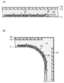
- FIG. 2 shows a cross section of a refrigerator according to an embodiment of the present invention.
- 2A shows an enlarged cross section of the flat portion of the inner box 11
- FIG. 2B shows an enlarged cross section of the corner portion of the inner box 11.
- a VIP 13 having a thickness of several millimeters is attached to the inner surface of the outer box 12, and the gap between the inner box 11 and the VIP 13 is 22 mm.
- angular part of the inner box 11 is carrying out the shape rounded by the curvature radius of a suitable magnitude
- AWG American Wire Gauge
- these wirings 30 When these wirings 30 are bundled in a round shape, the diameter thereof may be substantially the same as the thickness of the foam heat insulating material 14, and when the urethane foam is injected, the flow path is obstructed and void is generated.
- these wirings 30 are flattened and thinned by the binding tool 40, and the thickness is only about several millimeters. Therefore, urethane foam is injected into the space between the inner box 11 and the outer box 12 without being obstructed, and generation of voids can be avoided.
- the thickness of the foam heat insulating material 14 can be ensured to be several tens of mm even at the thinnest position, and the heat insulation efficiency can be kept good.
- the binding tool 40 may be formed of a curable synthetic resin and cannot be easily deformed, or formed of a flexible material such as polyacetal or polyamide and attached to the inner box 11. It may be easily deformable. In the latter case, when attaching the wire harness 20 to the inner box 11, the binding tool 40 can be freely deformed according to the shape of the attachment location. Further, the binder 40 may be formed by laminating a thermoplastic resin sheet.
- FIG. 3 shows an example of a binding tool 40 formed of a flexible material.
- 3A is a plan view of the binding tool 40
- FIG. 3B is a side view of the binding tool 40 viewed from the I ′ side in FIG. 3A
- FIG. FIG. 4 is a cross-sectional view taken along the line II ′ in FIG.
- the binding tool 40 includes a base portion 41, a tie portion 42, and a hook portion 43.
- the base portion 41 and the tie portion 42 sandwich a plurality of wires (not shown).
- the base 41 is made of a flexible material and has a plate shape. In order to make the base 41 easy to bend, notches 45 may be provided on the back surface of the base 41 at appropriate intervals. Further, in order to facilitate attachment to the inner box 11, a double-sided tape may be attached to the back surface of the base 41.
- the tie portion 42 is made of a flexible material and has a long shape. One end of the tie portion 42 is integrally formed with one end of the base portion 41.
- the hook portion 43 is provided on the surface of the base portion 41 so as to protrude in the vertical direction in plan view.
- a hook 46 is provided at the upper end portion of the hook portion 43, and the hook 46 is caught at both ends in the width direction of the tie portion 42, thereby preventing the tie portion 42 from being detached in the vertical direction of the base portion 41.
- the wiring is sandwiched between the base portion 41 and the tie portion 42.
- the hook portion 43 also serves as a “partition” that prevents the wiring sandwiched between the base portion 41 and the tie portion 42 from shifting in the longitudinal direction of the base portion 41.
- a “partition” that prevents the wiring sandwiched between the base portion 41 and the tie portion 42 from shifting in the longitudinal direction of the base portion 41.
- the tie portion 42 can slide in the extending direction even when the tie portion 42 is hooked on the hook portion 43. That is, the tie portion 42 can freely move in the extending direction while the wiring is sandwiched between the base portion 41 and the tie portion 42. Thereby, the binding tool 40 can be freely bent in a state where the wires are bound. This is advantageous when the binding tool 40 is bent and attached in accordance with the shape of a curved surface such as a corner of the inner box 11.
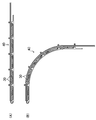
- FIG. 4 schematically shows a usage state of the binding tool 40 of FIG.
- FIG. 4A shows an example in the case where the binding tool 40 is used in a straight state
- FIG. 4B shows an example in which the binding tool 40 is used in a bent state.
- the plurality of wirings 30 are flatly bound by the binding tool 40 and are not easily separated.
- the wire harness 20 can be configured relatively inexpensively without using a special member. Then, by bundling the plurality of wirings 30 flatly by the binding tool 40, it is possible to sufficiently secure the urethane foam flow path at the time of forming the heat insulating layer and eliminate foaming defects such as void. Further, a large number of wirings 30 can be arranged at the corners without providing grooves or chamfering at the corners of the inner box 11. Therefore, according to this embodiment, the refrigerator interior volume ratio and the heat insulation efficiency can be improved relatively inexpensively.
- the refrigerator according to the present invention can improve the volume ratio and heat insulation efficiency at a relatively low cost, it is useful as a refrigerator or freezer for home use and business use.
Landscapes
- Engineering & Computer Science (AREA)
- General Engineering & Computer Science (AREA)
- Combustion & Propulsion (AREA)
- Physics & Mathematics (AREA)
- Mechanical Engineering (AREA)
- Thermal Sciences (AREA)
- Chemical & Material Sciences (AREA)
- Architecture (AREA)
- Civil Engineering (AREA)
- Structural Engineering (AREA)
- Refrigerator Housings (AREA)
- Supports For Pipes And Cables (AREA)
- Insertion, Bundling And Securing Of Wires For Electric Apparatuses (AREA)
- Insulating Bodies (AREA)
Abstract
Description
12 外箱
14 発泡断熱材
20 ワイヤハーネス
30 配線
40 結束具
41 基部
42 タイ部
43 フック部
Claims (3)
- 内箱と外箱との間の空間に発泡断熱材が充填され、複数の配線を束ねてなるワイヤハーネスが前記発泡断熱材に埋設された冷蔵庫であって、
前記ワイヤハーネスにおいて前記複数の配線の少なくとも1箇所が結束具によって扁平に結束されており、
前記結束具の少なくとも一つが前記複数の配線の延伸方向を軸として湾曲または屈曲しており、
前記内箱の2面が交わる角部において前記湾曲または屈曲した結束具が前記角部を巻き込むように前記内箱に取り付けられている
ことを特徴とする冷蔵庫。 - 請求項1に記載の冷蔵庫において、
前記結束具が可撓性を有する素材で形成されている
ことを特徴とする冷蔵庫。 - 請求項2に記載の冷蔵庫において、
前記結束具は、
可撓な板状の基部と、
一端が前記基部の一端と一体成型された長尺形状のタイ部と、
前記基部の表面に平面視垂直方向に突起して設けられ、前記タイ部が前記基部の平面視垂直方向へ離脱することを抑止しつつ前記タイ部が延伸方向に自在に移動できるように前記タイ部の少なくとも1箇所を掛止するフック部とを有するものであり、
前記複数の配線が前記基部と前記タイ部とで挟持されている
ことを特徴とする冷蔵庫。
Priority Applications (5)
| Application Number | Priority Date | Filing Date | Title |
|---|---|---|---|
| KR1020147034364A KR101650308B1 (ko) | 2012-06-07 | 2013-06-07 | 냉장고 |
| US14/406,456 US9528747B2 (en) | 2012-06-07 | 2013-06-07 | Refrigerator |
| JP2014519846A JPWO2013183304A1 (ja) | 2012-06-07 | 2013-06-07 | 冷蔵庫 |
| CN201380029862.0A CN104334986B (zh) | 2012-06-07 | 2013-06-07 | 冰箱 |
| EP13801002.0A EP2860478B1 (en) | 2012-06-07 | 2013-06-07 | Refrigerator |
Applications Claiming Priority (2)
| Application Number | Priority Date | Filing Date | Title |
|---|---|---|---|
| JP2012129596 | 2012-06-07 | ||
| JP2012-129596 | 2012-06-07 |
Publications (1)
| Publication Number | Publication Date |
|---|---|
| WO2013183304A1 true WO2013183304A1 (ja) | 2013-12-12 |
Family
ID=49711709
Family Applications (1)
| Application Number | Title | Priority Date | Filing Date |
|---|---|---|---|
| PCT/JP2013/003606 Ceased WO2013183304A1 (ja) | 2012-06-07 | 2013-06-07 | 冷蔵庫 |
Country Status (6)
| Country | Link |
|---|---|
| US (1) | US9528747B2 (ja) |
| EP (1) | EP2860478B1 (ja) |
| JP (1) | JPWO2013183304A1 (ja) |
| KR (1) | KR101650308B1 (ja) |
| CN (1) | CN104334986B (ja) |
| WO (1) | WO2013183304A1 (ja) |
Cited By (8)
| Publication number | Priority date | Publication date | Assignee | Title |
|---|---|---|---|---|
| JP2016003780A (ja) * | 2014-06-13 | 2016-01-12 | 株式会社東芝 | 冷蔵庫 |
| WO2016163026A1 (ja) * | 2015-04-10 | 2016-10-13 | 三菱電機株式会社 | 冷蔵庫 |
| JP2016217704A (ja) * | 2016-08-25 | 2016-12-22 | 東芝ライフスタイル株式会社 | 断熱箱体 |
| JP2018194295A (ja) * | 2018-09-12 | 2018-12-06 | 東芝ライフスタイル株式会社 | 冷蔵庫 |
| JP2019138532A (ja) * | 2018-02-09 | 2019-08-22 | 日立グローバルライフソリューションズ株式会社 | 冷蔵庫 |
| JP2020109352A (ja) * | 2018-09-12 | 2020-07-16 | 東芝ライフスタイル株式会社 | 冷蔵庫 |
| JP2020169815A (ja) * | 2020-07-22 | 2020-10-15 | 東芝ライフスタイル株式会社 | 冷蔵庫 |
| JPWO2020003587A1 (ja) * | 2018-06-25 | 2021-07-15 | シャープ株式会社 | 冷蔵庫 |
Families Citing this family (2)
| Publication number | Priority date | Publication date | Assignee | Title |
|---|---|---|---|---|
| CN109708374A (zh) * | 2019-01-28 | 2019-05-03 | 长虹美菱股份有限公司 | 一种薄壁冰箱 |
| EP4388257A1 (de) * | 2021-09-01 | 2024-06-26 | Liebherr-Hausgeräte Lienz GmbH | Verfahren zum anordnen eines elektrischen oder elektronischen bauelementes an einem kühl- und/oder gefriergerät |
Citations (6)
| Publication number | Priority date | Publication date | Assignee | Title |
|---|---|---|---|---|
| JPS6431309A (en) * | 1987-07-08 | 1989-02-01 | Minnesota Mining & Mfg | Wiring harness |
| JPH05205532A (ja) | 1992-01-23 | 1993-08-13 | Sharp Corp | 冷凍冷蔵庫用ハーネス組品 |
| JPH07222332A (ja) * | 1994-01-31 | 1995-08-18 | Sharp Corp | 取付装置 |
| JPH07294104A (ja) | 1994-04-21 | 1995-11-10 | Hitachi Ltd | 冷蔵庫 |
| JP2006162144A (ja) | 2004-12-07 | 2006-06-22 | Sharp Corp | 冷蔵庫 |
| JP2012002394A (ja) * | 2010-06-15 | 2012-01-05 | Panasonic Corp | 冷蔵庫 |
Family Cites Families (24)
| Publication number | Priority date | Publication date | Assignee | Title |
|---|---|---|---|---|
| US3346688A (en) * | 1964-11-12 | 1967-10-10 | Litton Systems Inc | Fork-type wiring harness |
| US3883198A (en) * | 1973-09-07 | 1975-05-13 | Whirlpool Co | Cabinet construction |
| CN1029359C (zh) * | 1989-04-11 | 1995-07-19 | 明尼苏达州探矿制造公司 | 导线布线和固定装置 |
| US5188319A (en) * | 1992-01-27 | 1993-02-23 | Navistar International Transportation Corp. | Clamp for hoses, tubing and/or electrical harnesses |
| DE4204187C2 (de) * | 1992-02-13 | 1993-12-02 | Raymond A Gmbh & Co Kg | Kabelkanal zur Aufnahme von Kabelbündel |
| US5632457A (en) * | 1994-12-12 | 1997-05-27 | Navistar International Transportation Corp. | Adjustable routing clamp assembly |
| US5828009A (en) * | 1996-10-17 | 1998-10-27 | Bentley-Harris Inc. | Wiring harness breakout clip with a pair of locating posts and flexible retaining bands |
| US5960522A (en) | 1997-05-21 | 1999-10-05 | Micron Electronics, Inc. | Ribbon cable alligator clamp |
| FR2811816B1 (fr) * | 2000-07-13 | 2002-10-11 | Cit Alcatel | Support pour elements filiformes de faible diametre et faisceau d'elements filiformes relies entre eux par ce support |
| DE20016363U1 (de) * | 2000-09-21 | 2001-01-18 | Igus Spritzgußteile für die Industrie GmbH, 51147 Köln | Energieführungskette |
| DE10050279A1 (de) | 2000-10-10 | 2002-04-25 | Taller Gmbh | Flexfolienverlegehilfe |
| GB0030569D0 (en) | 2000-12-13 | 2001-01-31 | Smiths Group Plc | Cables cable systems parts and methods |
| US20040135039A1 (en) * | 2003-01-09 | 2004-07-15 | Reichert Lucas Carl | Controlling and identifying system of holders for intravenous lines and other elongated members |
| JP4521699B2 (ja) | 2005-01-25 | 2010-08-11 | 株式会社ニックス | 固定具 |
| DE102005004453A1 (de) * | 2005-02-01 | 2006-08-10 | Volkswagen Ag | Krümmbarer Leitungskanal zur Aufnahme von Leitungen |
| US8048510B2 (en) * | 2005-09-21 | 2011-11-01 | Whirlpool Corporation | Liner with electrical pathways |
| JP4575273B2 (ja) * | 2005-10-28 | 2010-11-04 | 三菱電機株式会社 | 冷蔵庫 |
| KR20090006389A (ko) * | 2007-07-11 | 2009-01-15 | 엘지전자 주식회사 | 냉장고 |
| DE102008044251A1 (de) * | 2008-12-02 | 2010-06-10 | Manroland Ag | Falztrichteranordnung |
| CN102055150A (zh) | 2009-11-05 | 2011-05-11 | 鸿富锦精密工业(深圳)有限公司 | 线夹 |
| JP5084816B2 (ja) * | 2009-12-02 | 2012-11-28 | 三菱電機株式会社 | 空気調和機の内外通信線固定構造 |
| DE102010039500A1 (de) * | 2010-08-19 | 2012-02-23 | BSH Bosch und Siemens Hausgeräte GmbH | Abstandshalterung |
| US8277245B2 (en) * | 2010-09-24 | 2012-10-02 | Raytheon Company | Methods and systems for forming discrete wire ribbon cables |
| DE102010043239A1 (de) * | 2010-11-03 | 2012-05-03 | BSH Bosch und Siemens Hausgeräte GmbH | Kältegerät mit Leitungshalter sowie Verfahren zu dessen Herstellung |
-
2013
- 2013-06-07 US US14/406,456 patent/US9528747B2/en active Active
- 2013-06-07 KR KR1020147034364A patent/KR101650308B1/ko not_active Expired - Fee Related
- 2013-06-07 EP EP13801002.0A patent/EP2860478B1/en not_active Not-in-force
- 2013-06-07 CN CN201380029862.0A patent/CN104334986B/zh not_active Expired - Fee Related
- 2013-06-07 WO PCT/JP2013/003606 patent/WO2013183304A1/ja not_active Ceased
- 2013-06-07 JP JP2014519846A patent/JPWO2013183304A1/ja active Pending
Patent Citations (6)
| Publication number | Priority date | Publication date | Assignee | Title |
|---|---|---|---|---|
| JPS6431309A (en) * | 1987-07-08 | 1989-02-01 | Minnesota Mining & Mfg | Wiring harness |
| JPH05205532A (ja) | 1992-01-23 | 1993-08-13 | Sharp Corp | 冷凍冷蔵庫用ハーネス組品 |
| JPH07222332A (ja) * | 1994-01-31 | 1995-08-18 | Sharp Corp | 取付装置 |
| JPH07294104A (ja) | 1994-04-21 | 1995-11-10 | Hitachi Ltd | 冷蔵庫 |
| JP2006162144A (ja) | 2004-12-07 | 2006-06-22 | Sharp Corp | 冷蔵庫 |
| JP2012002394A (ja) * | 2010-06-15 | 2012-01-05 | Panasonic Corp | 冷蔵庫 |
Non-Patent Citations (1)
| Title |
|---|
| See also references of EP2860478A4 |
Cited By (13)
| Publication number | Priority date | Publication date | Assignee | Title |
|---|---|---|---|---|
| CN105300010A (zh) * | 2014-06-13 | 2016-02-03 | 株式会社东芝 | 冰箱 |
| CN105300010B (zh) * | 2014-06-13 | 2018-04-03 | 东芝生活电器株式会社 | 冰箱 |
| JP2016003780A (ja) * | 2014-06-13 | 2016-01-12 | 株式会社東芝 | 冷蔵庫 |
| WO2016163026A1 (ja) * | 2015-04-10 | 2016-10-13 | 三菱電機株式会社 | 冷蔵庫 |
| JPWO2016163026A1 (ja) * | 2015-04-10 | 2017-10-26 | 三菱電機株式会社 | 冷蔵庫 |
| JP2016217704A (ja) * | 2016-08-25 | 2016-12-22 | 東芝ライフスタイル株式会社 | 断熱箱体 |
| JP2019138532A (ja) * | 2018-02-09 | 2019-08-22 | 日立グローバルライフソリューションズ株式会社 | 冷蔵庫 |
| JPWO2020003587A1 (ja) * | 2018-06-25 | 2021-07-15 | シャープ株式会社 | 冷蔵庫 |
| JP7228589B2 (ja) | 2018-06-25 | 2023-02-24 | シャープ株式会社 | 冷蔵庫 |
| JP2018194295A (ja) * | 2018-09-12 | 2018-12-06 | 東芝ライフスタイル株式会社 | 冷蔵庫 |
| JP2020109352A (ja) * | 2018-09-12 | 2020-07-16 | 東芝ライフスタイル株式会社 | 冷蔵庫 |
| JP2020169815A (ja) * | 2020-07-22 | 2020-10-15 | 東芝ライフスタイル株式会社 | 冷蔵庫 |
| JP7227196B2 (ja) | 2020-07-22 | 2023-02-21 | 東芝ライフスタイル株式会社 | 冷蔵庫 |
Also Published As
| Publication number | Publication date |
|---|---|
| CN104334986B (zh) | 2016-09-14 |
| KR101650308B1 (ko) | 2016-09-05 |
| KR20150018550A (ko) | 2015-02-23 |
| EP2860478A1 (en) | 2015-04-15 |
| CN104334986A (zh) | 2015-02-04 |
| US20150145398A1 (en) | 2015-05-28 |
| US9528747B2 (en) | 2016-12-27 |
| EP2860478A4 (en) | 2016-01-20 |
| EP2860478B1 (en) | 2017-12-27 |
| JPWO2013183304A1 (ja) | 2016-01-28 |
Similar Documents
| Publication | Publication Date | Title |
|---|---|---|
| WO2013183304A1 (ja) | 冷蔵庫 | |
| US9484131B2 (en) | Method and device for positioning electrical conductors, and conductor group | |
| US10249408B2 (en) | Electrical cable, terminal-equipped electrical cable, and method of manufacturing terminal-equipped electrical cable | |
| CN103208760A (zh) | 线束和布线器具 | |
| JP2013016367A (ja) | コネクタ支持具、配線具及びワイヤハーネス | |
| JP2013013177A (ja) | 経路維持部材付コルゲートチューブ及びワイヤーハーネス | |
| JP2012110100A (ja) | ワイヤーハーネス | |
| CN105375230B (zh) | 绝缘触轮 | |
| US10819094B2 (en) | Protector-equipped electric wire and protector-equipped wire arrangement structure | |
| CN102570162A (zh) | 电连接器 | |
| CN114914864B (zh) | 配线部件的固定构造 | |
| CN112154521A (zh) | 配线构件 | |
| JP6386255B2 (ja) | ワイヤーハーネス | |
| JP2017108587A (ja) | コネクタおよびワイヤハーネス | |
| CN102377129B (zh) | 理线器 | |
| US10343627B2 (en) | Wire harness with connection member | |
| CN110417158B (zh) | 一种绝缘骨架及具有其的定子组件和电机 | |
| JP2016165166A (ja) | 保護部材付電線の配設構造及び保護部材付電線 | |
| CN203399834U (zh) | 用于储物柜的固定结构及具有该固定结构的家用电器 | |
| JP4430994B2 (ja) | ワイヤハーネスの組付構造 | |
| JP2010233295A (ja) | ワイヤハーネス用クランプ | |
| US9748756B2 (en) | Cable combination device | |
| JP6118148B2 (ja) | ワイヤハーネス | |
| JP2015149829A (ja) | ワイヤハーネスの固定構造 | |
| US8574002B2 (en) | Connector and connecting structure of flexible flat cable |
Legal Events
| Date | Code | Title | Description |
|---|---|---|---|
| 121 | Ep: the epo has been informed by wipo that ep was designated in this application |
Ref document number: 13801002 Country of ref document: EP Kind code of ref document: A1 |
|
| ENP | Entry into the national phase |
Ref document number: 2014519846 Country of ref document: JP Kind code of ref document: A |
|
| WWE | Wipo information: entry into national phase |
Ref document number: 2013801002 Country of ref document: EP |
|
| ENP | Entry into the national phase |
Ref document number: 20147034364 Country of ref document: KR Kind code of ref document: A |
|
| NENP | Non-entry into the national phase |
Ref country code: DE |
|
| WWE | Wipo information: entry into national phase |
Ref document number: 14406456 Country of ref document: US |