WO2013186996A1 - Dispositif de conversion de puissance électrique - Google Patents
Dispositif de conversion de puissance électrique Download PDFInfo
- Publication number
- WO2013186996A1 WO2013186996A1 PCT/JP2013/003294 JP2013003294W WO2013186996A1 WO 2013186996 A1 WO2013186996 A1 WO 2013186996A1 JP 2013003294 W JP2013003294 W JP 2013003294W WO 2013186996 A1 WO2013186996 A1 WO 2013186996A1
- Authority
- WO
- WIPO (PCT)
- Prior art keywords
- terminal
- operation mode
- power
- circuit
- rectifier
- Prior art date
- Legal status (The legal status is an assumption and is not a legal conclusion. Google has not performed a legal analysis and makes no representation as to the accuracy of the status listed.)
- Ceased
Links
Images


Classifications
-
- H—ELECTRICITY
- H02—GENERATION; CONVERSION OR DISTRIBUTION OF ELECTRIC POWER
- H02M—APPARATUS FOR CONVERSION BETWEEN AC AND AC, BETWEEN AC AND DC, OR BETWEEN DC AND DC, AND FOR USE WITH MAINS OR SIMILAR POWER SUPPLY SYSTEMS; CONVERSION OF DC OR AC INPUT POWER INTO SURGE OUTPUT POWER; CONTROL OR REGULATION THEREOF
- H02M3/00—Conversion of DC power input into DC power output
- H02M3/22—Conversion of DC power input into DC power output with intermediate conversion into AC
- H02M3/24—Conversion of DC power input into DC power output with intermediate conversion into AC by static converters
- H02M3/28—Conversion of DC power input into DC power output with intermediate conversion into AC by static converters using discharge tubes with control electrode or semiconductor devices with control electrode to produce the intermediate AC
- H02M3/325—Conversion of DC power input into DC power output with intermediate conversion into AC by static converters using discharge tubes with control electrode or semiconductor devices with control electrode to produce the intermediate AC using devices of a triode or a transistor type requiring continuous application of a control signal
- H02M3/335—Conversion of DC power input into DC power output with intermediate conversion into AC by static converters using discharge tubes with control electrode or semiconductor devices with control electrode to produce the intermediate AC using devices of a triode or a transistor type requiring continuous application of a control signal using semiconductor devices only
- H02M3/33507—Conversion of DC power input into DC power output with intermediate conversion into AC by static converters using discharge tubes with control electrode or semiconductor devices with control electrode to produce the intermediate AC using devices of a triode or a transistor type requiring continuous application of a control signal using semiconductor devices only with automatic control of the output voltage or current, e.g. flyback converters
-
- H—ELECTRICITY
- H02—GENERATION; CONVERSION OR DISTRIBUTION OF ELECTRIC POWER
- H02M—APPARATUS FOR CONVERSION BETWEEN AC AND AC, BETWEEN AC AND DC, OR BETWEEN DC AND DC, AND FOR USE WITH MAINS OR SIMILAR POWER SUPPLY SYSTEMS; CONVERSION OF DC OR AC INPUT POWER INTO SURGE OUTPUT POWER; CONTROL OR REGULATION THEREOF
- H02M3/00—Conversion of DC power input into DC power output
- H02M3/22—Conversion of DC power input into DC power output with intermediate conversion into AC
- H02M3/24—Conversion of DC power input into DC power output with intermediate conversion into AC by static converters
- H02M3/28—Conversion of DC power input into DC power output with intermediate conversion into AC by static converters using discharge tubes with control electrode or semiconductor devices with control electrode to produce the intermediate AC
- H02M3/325—Conversion of DC power input into DC power output with intermediate conversion into AC by static converters using discharge tubes with control electrode or semiconductor devices with control electrode to produce the intermediate AC using devices of a triode or a transistor type requiring continuous application of a control signal
- H02M3/335—Conversion of DC power input into DC power output with intermediate conversion into AC by static converters using discharge tubes with control electrode or semiconductor devices with control electrode to produce the intermediate AC using devices of a triode or a transistor type requiring continuous application of a control signal using semiconductor devices only
- H02M3/33569—Conversion of DC power input into DC power output with intermediate conversion into AC by static converters using discharge tubes with control electrode or semiconductor devices with control electrode to produce the intermediate AC using devices of a triode or a transistor type requiring continuous application of a control signal using semiconductor devices only having several active switching elements
- H02M3/33576—Conversion of DC power input into DC power output with intermediate conversion into AC by static converters using discharge tubes with control electrode or semiconductor devices with control electrode to produce the intermediate AC using devices of a triode or a transistor type requiring continuous application of a control signal using semiconductor devices only having several active switching elements having at least one active switching element at the secondary side of an isolation transformer
- H02M3/33584—Bidirectional converters
-
- H—ELECTRICITY
- H02—GENERATION; CONVERSION OR DISTRIBUTION OF ELECTRIC POWER
- H02M—APPARATUS FOR CONVERSION BETWEEN AC AND AC, BETWEEN AC AND DC, OR BETWEEN DC AND DC, AND FOR USE WITH MAINS OR SIMILAR POWER SUPPLY SYSTEMS; CONVERSION OF DC OR AC INPUT POWER INTO SURGE OUTPUT POWER; CONTROL OR REGULATION THEREOF
- H02M3/00—Conversion of DC power input into DC power output
- H02M3/22—Conversion of DC power input into DC power output with intermediate conversion into AC
- H02M3/24—Conversion of DC power input into DC power output with intermediate conversion into AC by static converters
- H02M3/28—Conversion of DC power input into DC power output with intermediate conversion into AC by static converters using discharge tubes with control electrode or semiconductor devices with control electrode to produce the intermediate AC
- H02M3/325—Conversion of DC power input into DC power output with intermediate conversion into AC by static converters using discharge tubes with control electrode or semiconductor devices with control electrode to produce the intermediate AC using devices of a triode or a transistor type requiring continuous application of a control signal
- H02M3/335—Conversion of DC power input into DC power output with intermediate conversion into AC by static converters using discharge tubes with control electrode or semiconductor devices with control electrode to produce the intermediate AC using devices of a triode or a transistor type requiring continuous application of a control signal using semiconductor devices only
- H02M3/337—Conversion of DC power input into DC power output with intermediate conversion into AC by static converters using discharge tubes with control electrode or semiconductor devices with control electrode to produce the intermediate AC using devices of a triode or a transistor type requiring continuous application of a control signal using semiconductor devices only in push-pull configuration
- H02M3/3376—Conversion of DC power input into DC power output with intermediate conversion into AC by static converters using discharge tubes with control electrode or semiconductor devices with control electrode to produce the intermediate AC using devices of a triode or a transistor type requiring continuous application of a control signal using semiconductor devices only in push-pull configuration with automatic control of output voltage or current
-
- H—ELECTRICITY
- H02—GENERATION; CONVERSION OR DISTRIBUTION OF ELECTRIC POWER
- H02M—APPARATUS FOR CONVERSION BETWEEN AC AND AC, BETWEEN AC AND DC, OR BETWEEN DC AND DC, AND FOR USE WITH MAINS OR SIMILAR POWER SUPPLY SYSTEMS; CONVERSION OF DC OR AC INPUT POWER INTO SURGE OUTPUT POWER; CONTROL OR REGULATION THEREOF
- H02M1/00—Details of apparatus for conversion
- H02M1/0067—Converter structures employing plural converter units, other than for parallel operation of the units on a single load
- H02M1/0074—Plural converter units whose inputs are connected in series
-
- H—ELECTRICITY
- H02—GENERATION; CONVERSION OR DISTRIBUTION OF ELECTRIC POWER
- H02M—APPARATUS FOR CONVERSION BETWEEN AC AND AC, BETWEEN AC AND DC, OR BETWEEN DC AND DC, AND FOR USE WITH MAINS OR SIMILAR POWER SUPPLY SYSTEMS; CONVERSION OF DC OR AC INPUT POWER INTO SURGE OUTPUT POWER; CONTROL OR REGULATION THEREOF
- H02M1/00—Details of apparatus for conversion
- H02M1/0067—Converter structures employing plural converter units, other than for parallel operation of the units on a single load
- H02M1/0077—Plural converter units whose outputs are connected in series
-
- H—ELECTRICITY
- H02—GENERATION; CONVERSION OR DISTRIBUTION OF ELECTRIC POWER
- H02M—APPARATUS FOR CONVERSION BETWEEN AC AND AC, BETWEEN AC AND DC, OR BETWEEN DC AND DC, AND FOR USE WITH MAINS OR SIMILAR POWER SUPPLY SYSTEMS; CONVERSION OF DC OR AC INPUT POWER INTO SURGE OUTPUT POWER; CONTROL OR REGULATION THEREOF
- H02M1/00—Details of apparatus for conversion
- H02M1/0083—Converters characterised by their input or output configuration
- H02M1/0093—Converters characterised by their input or output configuration wherein the output is created by adding a regulated voltage to or subtracting it from an unregulated input
Definitions
- the present invention relates to a power conversion device that converts DC power bidirectionally using a transformer.
- a power conversion device converts a DC power from a DC power source into a desired DC power and outputs it to the secondary side with a DC power source connected to the primary side and a storage battery connected to the secondary side. Can be charged. Also, the power conversion device discharges the storage battery by converting the DC power from the storage battery to the desired DC power and outputting it to the primary side with the load connected to the primary side and the storage battery connected to the secondary side. Can do.
- a device (bidirectional DC / DC converter) having a mutual DC conversion function between a first DC power source or first load and a second load or second DC power source.
- the power conversion device described in Literature 1 includes a primary side circuit including a first DC power source or a first load, a secondary side circuit including a second load or a second DC power source, a primary side circuit, and a second side circuit. And a transformer provided between the secondary circuit and the secondary circuit.
- the power conversion device described in Document 1 includes a bridge circuit configured by four semiconductor switches in each of the primary side circuit and the secondary side circuit.
- This power converter supplies power transformed by the transformer transformation ratio from the primary side circuit to the secondary side circuit by synchronizing the operations of the semiconductor switches of both bridge circuits, and also from the secondary side circuit. Supply power transformed at the transformer transformation ratio to the side circuit.
- the direction of boosting is fixed by the transformer's transformation ratio (turn ratio), so that boosting in both directions is not possible. That is, if the power conversion device has a configuration in which power conversion from the primary side to the secondary side is boosted, power conversion in the reverse direction (secondary side to primary side) is stepped down. Therefore, for example, when this power conversion device is used for charging and discharging a storage battery, it boosts the DC power from the DC power source when charging the storage battery to charge the storage battery, and boosts the DC power from the storage battery when discharging the storage battery. And cannot be used to supply the load.
- the present invention has been made in view of the above reasons, and an object thereof is to provide a power conversion device capable of boosting in both directions while using a transformer.
- a power conversion device including a transformer provided between a first terminal and a second terminal, and between the first terminal and the first winding of the transformer.
- a first conversion unit provided; and a second conversion unit provided between the second terminal and the second winding of the transformer, the direct current power from the first terminal being a desired voltage
- a first operation mode in which the direct current power is converted and output to the second terminal, and direct current power from the second terminal is converted into direct current power of a desired voltage and output to the first terminal.
- a power conversion device having two operation modes wherein the first conversion unit includes a first conversion circuit that performs bidirectional power conversion between the first terminal and the first winding; A first rectifier circuit that receives power supply from one winding and outputs DC power; and the first rectifier for the first terminal.
- a first switching unit that switches a circuit connection state between the first operation mode and the second operation mode, and the first operation mode is switched by switching the connection state in the first switching unit; Then, DC power from the first terminal is supplied to the second conversion unit through the first conversion circuit and the transformer, and the output voltage of the first conversion circuit is supplied to the first conversion circuit in the second operation mode. A voltage obtained by adding the output voltages of the rectifier circuit is output to the first terminal.
- the power conversion device switches the connection state of the first rectifier circuit with respect to the first terminal between the first operation mode and the second operation mode at the first switching unit.
- the first converter supplies DC power from the first terminal to the second converter through the first converter circuit and the transformer in the first operation mode, and the first converter circuit in the second operation mode.
- a voltage obtained by adding the output voltage of the first rectifier circuit to the output voltage is output to the first terminal. Therefore, there is an advantage that the voltage can be boosted in both directions while using a transformer.
- the transformer in the first mode, is connected to the first main winding connected to the first converter circuit and the first rectifier circuit. And the first auxiliary winding as the first winding.
- the first converter circuit in the second mode, includes a first rectifier connected to the first main winding, and the first rectifier.
- a first capacitor connected to the direct current output of the second rectifier, and the first rectifier circuit is connected to the second rectifier connected to the first auxiliary winding and to the direct current output of the second rectifier.
- the switching element is connected between both ends of the capacitor, and is configured to be short-circuited between both ends of the second capacitor by being turned on in the first operation mode and to be turned off in the second operation mode.
- the 1st rectifier circuit is inserted between the 2nd capacitor and the 1st change part, and the 1st A first switch that is turned off in the operation mode and turned on in the second operation mode;
- the first capacitor and the second capacitor have the same charge amount in the second operation mode.
- the capacity is determined in accordance with the turn ratio between the first main winding and the first auxiliary winding.
- the first rectifier circuit and the first converter circuit are the first operation circuit in the second operation mode.
- the ripple generated in the output voltage of the rectifier circuit and the ripple generated in the output voltage of the first conversion circuit are connected to the first terminal so as to have opposite phases.
- the first converter has a plurality of the first rectifier circuits
- the first switching unit In the second operation mode, the unit switches the connection state of the plurality of first rectifier circuits to the first terminal, so that at least one of the plurality of first rectifier circuits is the first first rectifier circuit.
- a voltage obtained by adding the output voltage of the rectifier circuit to the output voltage of the first conversion circuit is output to the first terminal.
- the second converter is bidirectional between the second terminal and the second winding.
- a second conversion circuit for power conversion, a second rectification circuit for receiving DC power supplied from the second winding and outputting DC power, and a connection state of the second rectification circuit to the second terminal A second switching unit that switches between the first operation mode and the second operation mode, and the second terminal in the second operation mode by switching the connection state in the second switching unit. Is supplied to the first converter through the second converter circuit and the transformer, and the output voltage of the second rectifier circuit is supplied to the output voltage of the second converter circuit in the first operation mode. Output the added voltage to the second terminal It is configured.
- the transformer is connected to a second main winding connected to the second converter circuit and the second rectifier circuit. And the second auxiliary winding as the second winding.
- the second conversion circuit includes a third rectifier connected to the second main winding, and the third rectifier.
- a third capacitor connected to the DC output of the second rectifier, and the second rectifier circuit is connected to the fourth rectifier connected to the second auxiliary winding and to the DC output of the fourth rectifier.
- the second rectifier circuit is inserted between the fourth capacitor and the second switching unit, and the second A second switch that is turned off in the operation mode and turned on in the first operation mode;
- the third capacitor and the fourth capacitor have the same charge amount in the first operation mode.
- the capacity is determined in accordance with the turn ratio between the second main winding and the second auxiliary winding.
- the second rectifier circuit and the second converter circuit are the second converter circuit in the first operation mode.
- the ripple generated in the output voltage of the rectifier circuit and the ripple generated in the output voltage of the second conversion circuit are connected to the second terminal so that the phases are opposite to each other.
- the second converter has a plurality of the second rectifier circuits, and the second switching In the first operation mode, the unit switches the connection state of the plurality of second rectifier circuits to the second terminal, so that at least one of the plurality of second rectifier circuits is the second A voltage obtained by adding the output voltage of the rectifier circuit to the output voltage of the second conversion circuit is output to the second terminal.
- FIG. 6 is a circuit diagram illustrating a configuration of a modified example of the first embodiment.
- FIG. 10 is an explanatory diagram of an operation of a modified example of the first embodiment.
- FIG. 6 is a circuit diagram showing a configuration of another modification of the first embodiment. It is a block diagram which shows the structure of the power converter device which concerns on Embodiment 2.
- FIG. It is a block diagram which shows the structure of the power converter device which concerns on Embodiment 3.
- a storage battery (traveling battery) mounted on a vehicle that generates driving force during traveling using electric energy, such as an electric vehicle (EV) or a plug-in hybrid vehicle (PHEV).
- the power converter device used for charge and discharge of is illustrated.
- the vehicle may be an electric vehicle that uses electric energy stored in the storage battery for traveling, and is not limited to a four-wheeled vehicle but may be an electric two-wheeled vehicle.
- a power conversion device described below is installed in a house and supplies power to a vehicle (not shown) from a DC supply bus (not shown) provided in the house to charge a storage battery (not shown) of the vehicle. In addition, it is used to supply power to the DC supply bus by discharging the storage battery of the vehicle.
- the DC supply bus here is connected to a DC power source such as a solar power generation device, a fuel cell, or a stationary power storage device, and supplies DC power from these DC power sources to a power conditioner or the like.
- a power converter device may be used not only for a detached house but for an apartment house or a business establishment.
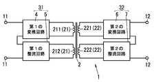
- the power conversion apparatus 1 As shown in FIG. 1, the power conversion apparatus 1 according to the present embodiment is provided between each pair of the first terminal 11 and the second terminal 12 and between the first terminal 11 and the second terminal 12. And a transformer 2. Furthermore, the power conversion device 1 includes a first conversion unit 31 provided between the first terminal 11 and the transformer 2, a second conversion unit 32 provided between the second terminal 12 and the transformer 2, and each unit. And a control unit (not shown) for overall control.
- a control part consists of microcomputers (microcomputer), for example.
- This power conversion device 1 has a function of converting DC power bidirectionally between the first terminal 11 and the second terminal 12, and the first winding 21 and the second winding of the transformer 2. Step-up (or step-down) is performed according to the turn ratio with 22 (that is, the transformation ratio of the transformer 2).
- the control unit controls the operations of the first conversion unit 31 and the second conversion unit 32, so that the direction of power conversion is performed between the first terminal 11 and the second terminal 12. Switch between two different operating modes. That is, the power conversion device 1 converts the DC power from the first terminal 11 into DC power of a desired voltage and outputs it to the second terminal 12, and the DC power from the second terminal 12. Is converted to DC power having a desired voltage and output to the first terminal 11.
- the power conversion device 1 switches the first conversion unit 31 and the second conversion unit 32 to perform PWM (Pulse Width Modulation) control and PPM (Pulse Phase Modulation) control, thereby stepping down at a desired transformation ratio. You can also
- the first terminal 11 is connected to the vehicle side (storage battery)
- the second terminal 12 is connected to the house side (DC supply bus)
- the power conversion device 1 is in the first operation mode when the storage battery is discharged. The case where it operates and operates in the 2nd operation mode at the time of charge of a storage battery is illustrated.
- the transformer 2 two windings of a (first) main winding 211 and a (first) auxiliary winding 212 are provided as the first winding 21 on the primary side (first terminal 11 side).
- a single second winding 22 is provided on the secondary side (second terminal 12 side).
- the number of turns of the main winding 211 is “n1”
- the number of turns of the auxiliary winding 212 is “n2”
- the number of turns of the second winding 22 is “m”.
- the transformer 2 has a turn ratio set so that at least “m> n1”.
- the first converter 31 is provided between the first terminal 11 and the first winding 21.
- the first converter 31 includes a (first) converter circuit 4 connected to the main winding 211, a (first) rectifier circuit 5 connected to the auxiliary winding 212, and a rectifier for the first terminal 11. And a (first) switching unit 50 that switches the connection state of the circuit 5.
- the switching unit 50 is incorporated in the rectifier circuit 5 in the example of FIG. 1, but may be provided separately from the rectifier circuit 5.
- the conversion circuit 4 bi-directionally converts power between the first terminal 11 and the first winding (main winding 211) 21. That is, in the first operation mode, the conversion circuit 4 converts DC power from the first terminal 11, outputs the DC power to the first winding (main winding 211) 21, and supplies power to the second winding 22. . In the second operation mode, the conversion circuit 4 receives power supply from the first winding (main winding 211) 21 and outputs DC power to the first terminal 11. In other words, the conversion circuit 4 functions as an inverter circuit that converts direct current into alternating current in the first operation mode, and functions as a rectifier circuit that converts alternating current into direct current in the second operation mode.
- the conversion circuit 4 includes a (first) capacitor 45, four switching elements 41 to 44 connected between both ends of the capacitor 45, and an inductor 46 as shown in FIG. ing.
- a series circuit of the switching elements 41 and 42 and a series circuit of the switching elements 43 and 44 are connected in parallel, and the conversion circuit 4 constitutes a full bridge type inverter circuit.
- a connection point between the switching elements 41 and 42 and a connection point between the switching elements 43 and 44 are connected to the main winding 211 via an inductor 46.
- the switching elements 41, 42, 43, and 44 are each composed of a MOSFET (Metal / Oxide / Semiconductor / Field / Effect / Transistor) that can be turned on / off by the control unit, and diodes 411, 421, 431, and 441 are anti-parallel between the respective drains and sources. It is connected to the.
- the diodes 411, 421, 431, and 441 may be MOSFET parasitic diodes.
- the switching elements 41, 42, 43, and 44 may be semiconductor switches other than MOSFETs.
- the converter circuit 4 converts the DC voltage across the capacitor 45 into an AC voltage by a switching operation in which the group of switching elements 41 and 44 and the group of switching elements 42 and 43 are alternately turned on. And applied to the first winding (main winding 211) 21.
- the conversion circuit 4 turns off all the switching elements 41 to 44 in the second operation mode, and uses the diode bridge formed of the diodes 411, 421, 431, and 441 as the first rectifier, and the first winding (the main winding 211). )
- the capacitor 45 is charged by receiving power from the power supply 21.
- the AC power from the first winding 21 is full-wave rectified by a diode bridge (first rectifier) including diodes 411, 421, 431, and 441 and smoothed by the capacitor 45.
- the control unit alternately turns on the pair of switching elements 41 and 44 and the pair of switching elements 42 and 43 in the first operation mode, and keeps the switching elements 41 to 44 off in the second operation mode.
- the switching elements 41 to 44 are controlled.
- the rectifier circuit 5 receives power supplied from the first winding (auxiliary winding 212) 21 and outputs DC power to the first terminal 11. In other words, the rectifier circuit 5 functions to convert alternating current into direct current in the second operation mode.
- the rectifier circuit 5 includes a diode 51, a (second) capacitor 52, and a switching element 53 connected in series between both ends of the auxiliary winding 212 as shown in FIG. .
- one end of the auxiliary winding 212 is connected to the cathode of the diode 51
- the other end of the auxiliary winding 212 is connected to one end of the switching element 53
- both ends of the capacitor 52 are connected to the anode of the diode 51 and the switching element 53.
- the switching element 53 is composed of a MOSFET that can be controlled to be turned on and off by a control unit, and a diode 531 is connected in antiparallel between a drain and a source.
- the diode 531 may be a MOSFET parasitic diode.
- the switching element 53 may be a semiconductor switch other than a MOSFET.
- the rectifier circuit 5 is electrically disconnected from the first winding (auxiliary winding 212) 21 by turning off the switching element 53 in the first operation mode, and the auxiliary winding 212 can be regarded as an open state. it can.
- the rectifier circuit 5 receives the power supply from the first winding (auxiliary winding 212) 21 by turning on the switching element 53 in the second operation mode and the diode 51 functioning as the second rectifier.
- the capacitor 52 is charged.
- AC power from the first winding 21 is half-wave rectified by a diode (second rectifier) 51 and smoothed by a capacitor 52 as a smoothing capacitor.
- the control unit controls the switching element 53 such that the switching element 53 is kept off in the first operation mode and the switching element 53 is kept on in the second operation mode.
- the (first) capacitor 45 of the converter circuit 4 and the (second) capacitor 52 of the rectifier circuit 5 are connected in series between the first terminals 11.
- the capacitor 45 is connected to the high potential side and the capacitor 52 is connected to the low potential side.
- the switching unit 50 is a switching element connected in series with the (first) capacitor 45 of the conversion circuit 4 and in parallel with the (second) capacitor 52 of the rectifier circuit 5.
- the switching unit 50 is composed of a MOSFET that can be controlled to be turned on / off by the control unit, and a diode 501 is connected in reverse parallel between the drain and the source.
- the diode 501 may be a parasitic diode of a MOSFET.
- the switching unit 50 may be a semiconductor switch other than a MOSFET.
- both ends of the capacitor 52 are short-circuited by the switching unit 50, and the capacitor 52 of the rectifier circuit 5 is bypassed between the first terminals 11, and the conversion circuit 4 is connected to the first terminal 11.
- the capacitor 45 is connected.
- the switching unit 50 is off, the capacitor 52 of the rectifier circuit 5 is not bypassed, so that the capacitor 45 of the conversion circuit 4 and the capacitor 52 of the rectifier circuit 5 are connected to the first terminal 11.
- the second converter 32 is provided between the second terminal 12 and the second winding 22 and bi-directionally converts power between the second terminal 12 and the second winding 22 (first 2) conversion circuit 6 is provided. That is, the conversion circuit 6 receives the power supply from the second winding 22 in the first operation mode and outputs DC power to the second terminal 12. In the second operation mode, the conversion circuit 6 converts DC power from the second terminal 12, outputs the DC power to the second winding 22, and supplies power to the first winding 21. In other words, the conversion circuit 6 functions as a rectifier circuit that converts alternating current into direct current in the first operation mode, and functions as an inverter circuit that converts direct current into alternating current in the second operation mode.
- the conversion circuit 6 includes a capacitor 65 and four switching elements 61 to 64 connected between both ends of the capacitor 65.
- a series circuit of the switching elements 61 and 62 and a series circuit of the switching elements 63 and 64 are connected in parallel, and the conversion circuit 6 is connected to the first conversion unit 31 ( Similar to the first conversion circuit 4, a full-bridge inverter circuit is configured.
- a connection point between the switching elements 61 and 62 and a connection point between the switching elements 63 and 64 are connected to the second winding 22.
- the switching elements 61, 62, 63, and 64 are formed of MOSFETs that can be controlled to be turned on and off by the control unit, and diodes 611, 621, 631, and 641 are connected in antiparallel between the drains and the sources.
- the diodes 611, 621, 631, and 641 may be MOSFET parasitic diodes.
- the switching elements 61, 62, 63, 64 may be semiconductor switches other than MOSFETs. That is, the (first) conversion circuit 4 of the first conversion unit 31 and the (second) conversion circuit 6 of the second conversion unit 32 are configured substantially symmetrically about the transformer 2.
- the conversion circuit 6 turns off all of the switching elements 61 to 64, and a diode bridge composed of the diodes 611, 621, 631, 641 functions as a third rectifier. Receiving the supply, the capacitor 65 is charged. At this time, the AC power from the second winding 22 is full-wave rectified by a diode bridge (third rectifier) including diodes 611, 621, 631 and 641 and smoothed by the capacitor 65.
- the conversion circuit 6 converts the DC voltage at both ends of the capacitor 65 to AC by switching operation in which the pair of switching elements 61 and 64 and the pair of switching elements 62 and 63 are alternately turned on.
- the voltage is converted and applied to the second winding 22.
- the control unit keeps the switching elements 61 to 64 off in the first operation mode, and alternately turns on the pair of switching elements 61 and 64 and the pair of switching elements 62 and 63 in the second operation mode.
- the switching elements 61 to 64 are controlled.
- the capacitor 65 of the conversion circuit 6 is connected to the second terminal 12. Therefore, in the state where the switching unit 50 is on and the capacitor 45 of the conversion circuit 4 is connected to the first terminal 11 as described above, the power conversion device 1 is connected to the first terminal 11 by the conversion circuits 4 and 6. DC power is converted bidirectionally with the second terminal 12. That is, if the switching unit 50 is fixed in the on state, the power conversion device 1 converts the DC power input from the first terminal 11 into the conversion circuit 4, the transformer 2, and the conversion in the first operation mode. The circuit 6 converts it into DC power having a desired voltage and outputs it from the second terminal 12. In the second operation mode, the power conversion apparatus 1 converts the DC power input from the second terminal 12 into DC power having a desired voltage by the conversion circuit 6, the transformer 2, and the conversion circuit 4. Is output from the terminal 11.
- the transformation ratio between the first terminal 11 and the second terminal 12 in this case is fixedly determined by the turn ratio between the main winding 211 and the second winding 22 of the first winding 21 in the transformer 2. . That is, the ratio between the voltage V1 between the first terminals 11 and the voltage V2 between the second terminals 12 is connected to the number n1 of the main winding 211 connected to the conversion circuit 4 and the conversion circuit 6. It depends on the ratio to the number m of turns of the second winding 22.
- the voltage V1 between the first terminals 11 is a voltage applied between the first terminals 11
- the voltage V2 between the second terminals 12 is a voltage applied between the second terminals 12. .
- the power conversion device 1 when the switching unit 50 is fixed in the ON state, the power conversion device 1 has a relationship of “m> n1” as described above, and therefore the transformation ratio is “V2> V1”. Become a relationship. In other words, in the power conversion device 1, only power conversion from the first terminal 11 to the second terminal 12 (first operation mode) is boosted, and power from the second terminal 12 to the first terminal 11 is increased. The conversion (second operation mode) is step-down.
- the switching unit 50 switches the connection state of the rectifier circuit 5 with respect to the first terminal 11 between the first operation mode and the second operation mode as described below. Bidirectional boosting is possible.
- the switching unit 50 is turned on in the first operation mode to short-circuit both ends of the capacitor 52 of the rectifier circuit 5 and is turned off in the second operation mode. Are switched between the first operation mode and the second operation mode.
- the first converter 31 supplies the DC power from the first terminal 11 to the second converter 32 through the converter circuit 4 and the transformer 2 in the first operation mode, and the converter circuit 4 in the second operation mode.
- a voltage obtained by adding the output voltage of the rectifier circuit 5 to the output voltage is output to the first terminal 11.
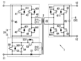
- FIGS. 2A and 2B Note that arrow A in FIG. 2A and arrow B in FIG. 2B indicate the direction of power conversion.
- the power conversion device 1 is configured such that, in the first operation mode in which power conversion is performed from the first terminal 11 to the second terminal 12, the switching unit 50 is turned on so that the first terminal 11 is connected to the capacitor 45 of the conversion circuit 4. At this time, the input current I1 from the first terminal 11 flows through the switching unit 50 and does not flow into the capacitor 52 of the rectifier circuit 5. Therefore, if the ON resistance of the switching unit 50 is negligible, a voltage having the same magnitude as the voltage V1 between the first terminals 11 is applied to the capacitor 45 of the conversion circuit 4. 2A, since the switching element 53 is turned off and the rectifier circuit 5 is electrically disconnected from the first winding (auxiliary winding 212) 21, the auxiliary winding 212 of the first winding 21 is It becomes an open state.
- the power conversion device 1 has the first terminal at a transformation ratio determined by the turns ratio (n1: m) between the main winding 211 and the second winding 22 of the first winding 21. 11 converts the DC power from 11 and outputs it to the second terminal 12.
- the turn ratio is in a relationship of “m> n1”
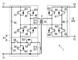
- the switching unit 50 in the power conversion device 1, in the second operation mode in which power conversion from the second terminal 12 to the first terminal 11 is performed, the switching unit 50 is turned off. At this time, in the rectifier circuit 5, the switching element 53 is turned on, and the diode 51 functions as the second rectifier, so that the current (half wave) I2 from the first winding (auxiliary winding 212) 21 is a capacitor. Then, the capacitor 52 is charged. Therefore, in the state of FIG. 2B, the voltage V1 between the first terminals 11 is a voltage obtained by adding the voltage V12 across the capacitor 52 to the voltage V11 across the capacitor 45.
- the ratio between the output voltage V11 of the conversion circuit 4 and the voltage V2 between the second terminals 12 is determined by the turn ratio (n1: m) between the main winding 211 and the second winding 22, and the conversion circuit. 4 output voltage V11 is represented by “V2 ⁇ n1 / m”. Further, the ratio between the output voltage V12 of the rectifier circuit 5 and the voltage V2 between the second terminals 12 is similarly determined by the turn ratio (n2: m) between the auxiliary winding 212 and the second winding 22, and the rectifier circuit. Assume that an output voltage V12 of 5 is represented by “V2 ⁇ n2 / m”. That is, it is assumed that the ratio “V11: V12” between the voltage V11 across the capacitor 45 and the voltage V12 across the capacitor 52 is represented by “n1: n2”.
- the conversion circuit 4 performs full-wave rectification, whereas the rectification circuit 5 performs half-wave rectification, so that the output voltage V11 of the conversion circuit 4 is not necessarily “V2 ⁇ n1 / m” as described above.
- the output voltage V12 of the rectifier circuit 5 is not always represented by “V2 ⁇ n2 / m”. However, for example, by adjusting the capacitance of the capacitor 45 of the conversion circuit 4 and the capacitor 52 of the rectifier circuit 5 or by making the rectifier circuit 5 a full-wave rectifier circuit, the output voltage V12 of the rectifier circuit 5 is set to “V2 ⁇ n2 / m ”is possible.
- the switching unit 50 switches the connection state of the rectifier circuit 5 to the first terminal 11 between the first operation mode and the second operation mode, so that the bidirectional Boosting is possible. That is, the first converter 31 supplies the DC power from the first terminal 11 to the second converter 32 through the converter circuit 4 and the transformer 2 in the first operation mode, and the output of the converter circuit 4 in the second operation mode. A voltage obtained by adding the output voltage of the rectifier circuit 5 to the voltage is output to the first terminal 11. Therefore, the power conversion device 1 converts power from the first terminal 11 to the second terminal 12 (first operation mode) and converts power from the second terminal 12 to the first terminal 11 (second operation). In both cases, the voltage can be boosted.
- the power conversion device 1 When the storage battery is discharged (first operation mode), the power conversion device 1 boosts the DC power input from the vehicle side (storage battery) to the first terminal 11 to the residential side from the second terminal 12. Can output to (DC supply bus). On the other hand, when the storage battery is charged (second operation mode), the power conversion device 1 boosts the DC power input from the house side (DC supply bus) to the second terminal 12 to increase the first power. It can output from the terminal 11 to the vehicle side (storage battery).
- the operation of the power converter 1 when the input / output voltage range on the vehicle side is 100 to 500 VDC and the input / output voltage range on the house side is 300 to 400 VDC will be described.
- the power conversion device 1 boosts the direct current 100V input to the first terminal 11 to the direct current 300V and outputs it from the second terminal 12 when the storage battery is discharged, and outputs the second terminal 12 when charging the storage battery.
- DC 300V input to 12 is boosted to 500V and output from the first terminal 11.
- the first terminal 11 may be connected to the house side
- the second terminal 12 may be connected to the vehicle side
- the input / output voltage ranges on the vehicle side and the house side are also described above. It is not limited to the value.
- the rectifier circuit 5 is inserted between the (second) capacitor 52 and the switching unit 50 (first )
- a switch 54 may be provided.
- the switch 54 is inserted between the connection point between the switching unit 50 and the switching element 53 and the capacitor 52, and is controlled to be turned on and off by the control unit.
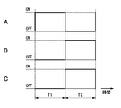
- FIG. 4A to 4C are timing charts showing operations of the switching unit 50, the switching element 53, and the switch 54 in the example of FIG. 4A represents the on / off state of the switching unit 50, FIG. 4B represents the on / off state of the switching element 53, and FIG. 4C represents the on / off state of the switch 54.
- the rectifier circuit 5 turns off the switch 54 and switches the capacitor 52 in the first operation mode (period T1) in which the switching unit 50 is on and the switching element 53 is off. Electrically disconnected from 50. As shown in FIGS. 4A to 4C, the rectifier circuit 5 turns on the switch 54 and turns on the capacitor 52 in the first operation mode (period T2) in which the switching unit 50 is off and the switching element 53 is on. The voltage across the capacitor 52 is output to the first terminal 11.
- the switch unit 50 when switching from the second operation mode to the first operation mode, the switch unit 50 is turned on and the switch 54 is turned off at the same time. 50 can be avoided. Therefore, the power conversion device 1 can prevent the circuit element from being stressed by a large current flowing from the capacitor 52 to the switching unit 50.
- the switch 54 for separating the capacitor 52 from the switching unit 50 may be provided at a position as shown in FIG.
- the power conversion device 1 includes a switch 54 between the connection point of the capacitor 45 and the capacitor 52 and the connection point of the switching element 42 and the switching unit 50.
- the rectifier circuit 5 turns off the switch 54 and electrically disconnects the capacitor 52 from the switching unit 50.
- the rectifier circuit 5 turns on the switch 54 to connect the capacitor 52 to the switching element 53 and supply power from the auxiliary winding 212.
- the capacitor 52 is charged.
- the power conversion device 1 (first) according to the turn ratio (n1: n2) between the main winding 211 and the auxiliary winding 212. It is desirable that the capacitances of the capacitor 45 and the (second) capacitor 52 are determined.
- the turn ratio “n1: n2” between the main winding 211 and the auxiliary winding 212 is “3: 1”
- the voltage across the capacitor 45 in the second operation mode is 300 V
- the ratio “C1: C2” between the capacitance C1 of the capacitor 45 and the capacitance C2 of the capacitor 52 is preferably “1: 3”. That is, the capacitance of the capacitor 45 and the capacitor 52 is determined according to the turn ratio (n1: n2) between the main winding 211 and the auxiliary winding 212 so that the charge amount in the second operation mode is the same. .
- the output voltage of the conversion circuit 4 is equal to the voltage across the capacitor 45 when the switch 54 is switched on and off.
- the output voltage of the rectifier circuit 5 matches the voltage across the capacitor 52.
- the specific configurations of the conversion circuit 4 and the rectifier circuit 5 in the first conversion unit 31 and the conversion circuit 6 in the second conversion unit 32 described in the present embodiment are not limited to the above-described configurations, and can be changed as appropriate.
- the rectifier circuit 5 may be a full-wave rectifier circuit using a diode bridge instead of the half-wave rectifier circuit as described above.
- the conversion circuit 4 rectifies by switching operation of the switching elements 41 to 44, for example, instead of a configuration in which all the switching elements 41 to 44 are turned off and rectified by the diode bridge. It may be a configuration.
- the conversion circuit 4 converts the alternating current power from the main winding 211 into direct current power by a switching operation in which the pair of switching elements 41 and 44 and the pair of switching elements 42 and 43 are alternately turned on, thereby converting the capacitor. 45 can be applied. The same applies to the conversion circuit 6.
- the transformer 2 is not limited to the configuration in which the first winding 21 is composed of two windings of the main winding 211 and the auxiliary winding 212, and the first winding 21 may be configured to be composed of one winding.
- the first converter 31 is configured by connecting the converter circuit 4 and the rectifier circuit 5 in parallel between both ends of the first winding 21.
- the transformer 2 divides the core into a first core provided with the first winding 21 and a second core provided with the second winding 22, whereby the first winding 21 and the first winding 21 are divided.
- segment 2 windings 22 may be sufficient.
- the power converter 1 can physically separate the first converter 31 and the second converter 32, and magnetically couples the core of the transformer 2 only when the storage battery is charged or discharged. Thus, the power can be exchanged between the first conversion unit 31 and the second conversion unit 32.
- Embodiment 2 In the power conversion device 1 of the present embodiment, the conversion circuit 4 and the rectifier circuit 5 in the first conversion unit 31 are arranged in such a manner that ripples (pulsations) generated in the output voltage in the second operation mode are in opposite phases. 1 is different from the power conversion device 1 of the first embodiment in that it is connected to the terminal 11 of the first embodiment.
- the same configurations as those of the first embodiment are denoted by common reference numerals, and description thereof is omitted as appropriate.
- the rectifier circuit 5 and the conversion circuit 4 have the first terminal 11 so that the ripple generated in the output voltage of the rectifier circuit 5 and the ripple generated in the output voltage of the conversion circuit 4 are in opposite phases in the second operation mode. It is connected to the.
- the power conversion device 1 is configured such that the winding direction is reversed between the main winding 211 and the auxiliary winding 212 of the transformer 2 as shown in FIG.
- the conversion circuit 4 connected to the main winding 211 is configured to perform half-wave rectification similarly to the rectification circuit 5 in the second operation mode.
- arrow B represents the direction of power conversion, and the voltage waveform at each part is illustrated.
- the ripple component superimposed on the output voltage of the conversion circuit 4 is out of phase with the ripple component superimposed on the output voltage of the rectifier circuit 5 in the second operation mode. Offset. Therefore, the power conversion device 1 makes the ripple component from the first terminal 11 in the second operation mode while the capacitors 45 and 52 (see FIG. 1) of the conversion circuit 4 and the rectifier circuit 5 have relatively small capacities. A small DC voltage can be output. As a result, there is an advantage that the capacitors 45 and 52 are reduced in size and cost.
- the configuration for making the ripples generated in the output voltage in the conversion circuit 4 and the rectifier circuit 5 in opposite phases is such that the winding direction is reversed between the main winding 211 and the auxiliary winding 212 as described above. It is not limited to the configuration.
- the conversion circuit 4 has a configuration in which AC power from the main winding 211 is half-wave rectified by the switching operation of the switching elements 41 to 44 so that the output to the first terminal 11 has a phase opposite to that of the rectifier circuit 5. There may be.
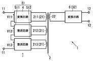
- the power conversion device 1 As shown in FIG. 7, the power conversion device 1 according to the present embodiment includes the plurality of rectifier circuits 511, 512,. Is different.
- the same configurations as those of the first embodiment are denoted by common reference numerals, and description thereof is omitted as appropriate.
- the switching unit 50 switches the connection state of the plurality of rectifier circuits 511, 512,... To the first terminal 11 between the first operation mode and the second operation mode.
- the first converter 31 outputs the output voltage of at least one rectifier circuit 511, 512,.
- the voltage added to the voltage is output to the first terminal 11.
- the switching unit 50 is connected between both ends of the capacitor 52 (see FIG. 1) of each rectifier circuit 511, 512,..., And in the first operation mode, all the rectifier circuits 511, 512,. .. Short-circuit between both ends of the capacitor 52.
- the second operation mode when at least one switching unit 50 is turned off, the output voltages V12, V13,... Of the rectifier circuits 511, 512,. At least one is added and output to the first terminal 11.
- the first terminal 11 in the second operation mode is connected to the conversion circuit 4 by connecting a plurality of rectifier circuits 511, 512,.
- the output voltage from can be switched in multiple stages.
- the power conversion device 1 As shown in FIG. 8, the power conversion device 1 according to the present embodiment is configured such that the second conversion unit 32 is configured to be symmetrical with the first conversion unit 31 with the transformer 2 as the center. This is different from the power conversion device 1.
- the same configurations as those of the first embodiment are denoted by common reference numerals, and description thereof is omitted as appropriate.
- the transformer 2 includes a second winding of a (second) main winding 221 and a (second) auxiliary winding 222 on the secondary side (second terminal 12 side). It is provided as a line 22.
- the second conversion unit 32 includes the (second) rectifier circuit 7 connected to the auxiliary winding 222 and the second terminal 12 in addition to the (second) conversion circuit 6 connected to the main winding 221. And a second switching unit (not shown) for switching the connection state of the rectifier circuit 7 to the.
- the conversion circuit 6 bi-directionally converts power between the second terminal 12 and the second winding (main winding 221) 22.
- the rectifier circuit 7 receives power supply from the second winding (auxiliary winding 222) 22 and outputs DC power.
- the second switching unit is incorporated in the rectifier circuit 7, but may be provided separately from the rectifier circuit 7. If the second terminal 12 is replaced with the first terminal 11 and the second winding 22 is replaced with the first winding 21, the conversion circuit 6 in the second conversion unit 32 corresponds to the conversion circuit 4 in the first conversion unit 31.
- the rectifier circuit 7 in the second converter 32 corresponds to the rectifier circuit 5 in the first converter 31.
- the conversion circuit 6 has a third rectifier (not shown) connected to the main winding 221 and a third capacitor (not shown) connected to the DC output of the third rectifier.
- the rectifier circuit 7 includes a fourth rectifier (not shown) connected to the auxiliary winding 222 and a fourth capacitor (not shown) connected to the DC output of the fourth rectifier.
- the third capacitor and the fourth capacitor are connected in series to the second terminal 12.
- the third rectifier corresponds to the first rectifier of the conversion circuit 4 (diodes 411, 421, 431, and 441 in FIG. 1), and the third capacitor corresponds to the (first) capacitor 45 of the conversion circuit 4.
- the fourth rectifier corresponds to the second rectifier (diode 51 in FIG. 1) of the rectifier circuit 5, and the fourth capacitor corresponds to the (second) capacitor 52 of the rectifier circuit 5. Therefore, illustration and detailed description of each component of the conversion circuit 6 and the rectifier circuit 7 are omitted here.
- the second switching unit corresponds to the (first) switching unit 50 in the first conversion unit 31. That is, the second switching unit includes a switching element connected between both ends of the fourth capacitor.
- the second switching unit is turned on in the second operation mode to short-circuit both ends of the fourth capacitor of the rectifier circuit 7 and is turned off in the first operation mode.
- the connection state is switched between the first operation mode and the second operation mode.
- the second converter 32 supplies the DC power from the second terminal 12 to the first converter 31 through the converter circuit 6 and the transformer 2 in the second operation mode, and the converter circuit 6 in the first operation mode.
- a voltage obtained by adding the output voltage of the rectifier circuit 7 to the output voltage is output to the second terminal 12.
- the first terminal 11 -second the first terminal 11 -second
- the step-up ratio between the terminals 12 can be matched in both directions.
- the power conversion device 1 includes a rectifier circuit 7 having a second switch (not shown) inserted between the fourth capacitor and the second switching unit. It may be.
- the second switch corresponds to the switch 54 of the modification of the first embodiment shown in FIG. Therefore, illustration and detailed description of the second switch are omitted here.
- the rectifier circuit 7 includes the second switch, the third capacitor and the fourth capacitor have the same amount of charge in the first operation mode so that the main winding 221 and the auxiliary winding 222 have the same amount of charge.
- the capacity may be determined according to the turn ratio.
- the configuration of the fourth embodiment (the second conversion unit 32 is symmetric with the first conversion unit 31) is appropriately combined with each configuration described in the first embodiment and each configuration described in the second and third embodiments. Can do.
- the conversion circuit 6 and the rectifier circuit 7 in the second conversion unit 32 have a ripple (pulsating flow) generated in the output voltage in the first operation mode.
- the second terminals 12 are connected so as to be in opposite phases.
- the second conversion unit 32 includes a plurality of second rectifier circuits.
- the second switching unit switches the connection state of the plurality of second rectifier circuits with respect to the second terminal 12 between the first operation mode and the second operation mode.
- the second conversion unit 32 adds a voltage obtained by adding the output voltage of at least one second rectifier circuit to the output voltage of the converter circuit 6 among the plurality of second rectifier circuits. Output to the second terminal 12.
- the power converter device 1 used for charge and discharge of the storage battery of a vehicle was illustrated, the power converter device 1 may be used for other uses, for example, other than charge and discharge of a storage battery May be used.
Landscapes
- Engineering & Computer Science (AREA)
- Power Engineering (AREA)
- Dc-Dc Converters (AREA)
Abstract
Le présent dispositif de conversion de puissance électrique (1) a un premier mode de fonctionnement dans lequel une puissance en courant continu provenant de premières bornes (11) est convertie en puissance en courant continu d'une tension désirée et transmise à de secondes bornes (12) et un second mode de fonctionnement dans lequel une puissance en courant continu provenant des secondes bornes (12) est convertie en puissance en courant continu d'une tension désirée et transmise aux premières bornes (11). Une partie de commutation (50) est activée de manière à court-circuiter un condensateur (52) d'un circuit de redressement (5) dans le premier mode de fonctionnement, et est désactivée dans le second mode de fonctionnement. Par conséquent, une première unité de conversion (31) fournit la puissance en courant continu provenant des premières bornes (11) à une seconde unité de conversion (32) à partir d'un premier fil d'enroulement (21) via un circuit de conversion (4) dans le premier mode de fonctionnement, et transmet une tension, laquelle est obtenue en ajoutant une tension de sortie du circuit de redressement (5) à une tension de sortie du circuit de conversion (4), aux premières bornes (11) dans le second mode de fonctionnement. Ainsi, l'augmentation de tension bidirectionnelle est permise en dépit de l'utilisation d'un transformateur.
Priority Applications (2)
| Application Number | Priority Date | Filing Date | Title |
|---|---|---|---|
| EP13804362.5A EP2863530A4 (fr) | 2012-06-14 | 2013-05-23 | Dispositif de conversion de puissance électrique |
| US14/406,730 US9209698B2 (en) | 2012-06-14 | 2013-05-23 | Electric power conversion device |
Applications Claiming Priority (2)
| Application Number | Priority Date | Filing Date | Title |
|---|---|---|---|
| JP2012-135098 | 2012-06-14 | ||
| JP2012135098A JP5903628B2 (ja) | 2012-06-14 | 2012-06-14 | 電力変換装置 |
Publications (1)
| Publication Number | Publication Date |
|---|---|
| WO2013186996A1 true WO2013186996A1 (fr) | 2013-12-19 |
Family
ID=49757845
Family Applications (1)
| Application Number | Title | Priority Date | Filing Date |
|---|---|---|---|
| PCT/JP2013/003294 Ceased WO2013186996A1 (fr) | 2012-06-14 | 2013-05-23 | Dispositif de conversion de puissance électrique |
Country Status (4)
| Country | Link |
|---|---|
| US (1) | US9209698B2 (fr) |
| EP (1) | EP2863530A4 (fr) |
| JP (1) | JP5903628B2 (fr) |
| WO (1) | WO2013186996A1 (fr) |
Families Citing this family (11)
| Publication number | Priority date | Publication date | Assignee | Title |
|---|---|---|---|---|
| DE102017106424B4 (de) * | 2017-03-24 | 2021-09-02 | Infineon Technologies Austria Ag | Leistungswandlerschaltung mit einem Hauptwandler und einem Hilfswandler |
| US11641122B2 (en) * | 2017-06-12 | 2023-05-02 | Gbatteries Energy Canada Inc. | Battery charging through multi-stage voltage conversion |
| CN107181413A (zh) * | 2017-07-15 | 2017-09-19 | 华北电力大学(保定) | 混合型直流电力电子变压器 |
| US10644607B2 (en) * | 2017-08-03 | 2020-05-05 | Futurewei Technologies, Inc. | Auxiliary power supply apparatus and method for isolated power converters |
| US11374500B2 (en) * | 2017-11-17 | 2022-06-28 | Rompower Technology Holdings, Llc | Harvesting energy from parasitic elements of a power converter |
| US10256729B1 (en) * | 2018-03-06 | 2019-04-09 | Infineon Technologies Austria Ag | Switched-capacitor converter with interleaved half bridge |
| US10263516B1 (en) * | 2018-03-06 | 2019-04-16 | Infineon Technologies Austria Ag | Cascaded voltage converter with inter-stage magnetic power coupling |
| CN112054657B (zh) | 2020-09-04 | 2022-06-07 | 昂宝电子(上海)有限公司 | 脉冲宽度调制控制芯片和电源转换系统 |
| CN112994466B (zh) * | 2021-02-23 | 2022-06-28 | 浙江大学 | 一种宽调压范围的变换器 |
| CN118783725A (zh) * | 2023-03-31 | 2024-10-15 | 日立能源有限公司 | 功率转换装置和系统以及用于操作该装置的方法 |
| AU2024246788A1 (en) * | 2023-03-31 | 2025-09-04 | Hitachi Energy Ltd | Apparatus and system for power conversion and method for operating the apparatus |
Citations (4)
| Publication number | Priority date | Publication date | Assignee | Title |
|---|---|---|---|---|
| JP2001211645A (ja) * | 2000-01-25 | 2001-08-03 | Hitachi Ltd | 直流電源装置 |
| JP2007174784A (ja) * | 2005-12-21 | 2007-07-05 | Hitachi Ltd | 双方向dc−dcコンバータおよびその制御方法 |
| JP2011050227A (ja) * | 2009-08-28 | 2011-03-10 | Fuji Heavy Ind Ltd | 双方向コンバータ及びこれを用いた電気自動車の制御装置 |
| JP2011234541A (ja) | 2010-04-28 | 2011-11-17 | Panasonic Electric Works Co Ltd | 双方向dc/dcコンバータ |
Family Cites Families (14)
| Publication number | Priority date | Publication date | Assignee | Title |
|---|---|---|---|---|
| US4719550A (en) * | 1986-09-11 | 1988-01-12 | Liebert Corporation | Uninterruptible power supply with energy conversion and enhancement |
| US5241217A (en) * | 1991-11-07 | 1993-08-31 | Premier Power, Inc. | UPS with input commutation between AC and DC sources of power |
| KR20010006576A (ko) | 1999-01-18 | 2001-01-26 | 가나이 쓰도무 | 전력축적수단의 충방전장치 및 그것을 사용한전력축적수단의 제조방법 |
| US6452815B1 (en) * | 2001-02-22 | 2002-09-17 | Lizhi Zhu | Accelerated commutation for passive clamp isolated boost converters |
| DE10218669B4 (de) * | 2002-04-26 | 2015-04-02 | Daimler Ag | Brennstoffzellensystem und Verfahren zur Spannungsüberwachung für ein Brennstoffzellensystem |
| US7408795B2 (en) | 2004-02-24 | 2008-08-05 | Vlt, Inc. | Energy storage and hold-up method and apparatus for high density power conversion |
| EP2019481A1 (fr) * | 2007-07-25 | 2009-01-28 | Danmarks Tekniske Universitet | Convertisseur CC-CC en mode commuté avec transformateurs d'alimentation multiple |
| US7796406B2 (en) * | 2007-07-31 | 2010-09-14 | Lumenis Ltd. | Apparatus and method for high efficiency isolated power converter |
| US8030788B2 (en) * | 2008-12-31 | 2011-10-04 | General Electric Company | Method and systems for an engine starter/generator |
| WO2010143758A1 (fr) * | 2009-06-10 | 2010-12-16 | 엘지전자 주식회사 | Dispositif de commande de moteur d'un climatiseur à alimentation électrique distribuée |
| US8866332B2 (en) * | 2009-06-24 | 2014-10-21 | Brusa Elektronik Ag | Circuit arrangement for power distribution in a motor vehicle |
| US8338987B2 (en) * | 2010-02-26 | 2012-12-25 | General Electric Company | Power generation frequency control |
| EP2569858B1 (fr) * | 2010-05-11 | 2018-07-11 | ABB Research Ltd. | Convertisseur ca-cc avec modules multi-cellules des phases en serie et pour chaque phase avec un circuit parallèle d'un condensateur blocage de courant continu en serie avec les bornes de sortie CA |
| US9290097B2 (en) * | 2010-11-05 | 2016-03-22 | Robert Louis Steigerwald | Apparatus for transferring energy using onboard power electronics with high-frequency transformer isolation and method of manufacturing same |
-
2012
- 2012-06-14 JP JP2012135098A patent/JP5903628B2/ja active Active
-
2013
- 2013-05-23 WO PCT/JP2013/003294 patent/WO2013186996A1/fr not_active Ceased
- 2013-05-23 EP EP13804362.5A patent/EP2863530A4/fr not_active Withdrawn
- 2013-05-23 US US14/406,730 patent/US9209698B2/en active Active
Patent Citations (4)
| Publication number | Priority date | Publication date | Assignee | Title |
|---|---|---|---|---|
| JP2001211645A (ja) * | 2000-01-25 | 2001-08-03 | Hitachi Ltd | 直流電源装置 |
| JP2007174784A (ja) * | 2005-12-21 | 2007-07-05 | Hitachi Ltd | 双方向dc−dcコンバータおよびその制御方法 |
| JP2011050227A (ja) * | 2009-08-28 | 2011-03-10 | Fuji Heavy Ind Ltd | 双方向コンバータ及びこれを用いた電気自動車の制御装置 |
| JP2011234541A (ja) | 2010-04-28 | 2011-11-17 | Panasonic Electric Works Co Ltd | 双方向dc/dcコンバータ |
Non-Patent Citations (1)
| Title |
|---|
| See also references of EP2863530A4 |
Also Published As
| Publication number | Publication date |
|---|---|
| JP5903628B2 (ja) | 2016-04-13 |
| US20150162841A1 (en) | 2015-06-11 |
| JP2013258883A (ja) | 2013-12-26 |
| US9209698B2 (en) | 2015-12-08 |
| EP2863530A1 (fr) | 2015-04-22 |
| EP2863530A4 (fr) | 2015-08-19 |
Similar Documents
| Publication | Publication Date | Title |
|---|---|---|
| JP5903628B2 (ja) | 電力変換装置 | |
| US8009443B2 (en) | DC/DC converter and AC/DC converter | |
| CN102282749B (zh) | 电力转换器 | |
| CN102577063B (zh) | Dc/dc变换器电路和电池系统 | |
| JP5855133B2 (ja) | 充電装置 | |
| CN105659484B (zh) | 电力变换装置 | |
| US10840814B2 (en) | Power conversion system | |
| JP5546685B2 (ja) | 充電装置 | |
| KR101769335B1 (ko) | 멀티 토플러지를 이용한 dc/dc 컨버터 | |
| JP2012210104A (ja) | 電力変換装置 | |
| KR101865246B1 (ko) | 전기자동차용 충방전 장치 | |
| JP6742145B2 (ja) | 双方向dc−dcコンバータ、これを用いた電源システム及び当該電源システムを用いた自動車 | |
| US11296607B2 (en) | DC-DC converter | |
| CN112714992A (zh) | 用于车辆侧电能存储器的充电电路 | |
| US11689112B2 (en) | DC-DC converter and vehicle | |
| JP6551340B2 (ja) | 電圧変換装置 | |
| JP6709965B2 (ja) | スナバ回路、及びそれを用いた電力変換システム | |
| JP2014171313A (ja) | Dc/dcコンバータ | |
| WO2022176589A1 (fr) | Convertisseur c.a.-c.c. | |
| JP6270753B2 (ja) | 電力変換装置 | |
| WO2016194712A1 (fr) | Dispositif de conversion de courant électrique de type isolé | |
| JP2014230392A (ja) | 双方向電源装置 | |
| KR20130083500A (ko) | 전해커패시터가 없는 단일단 배터리 충전기 |
Legal Events
| Date | Code | Title | Description |
|---|---|---|---|
| 121 | Ep: the epo has been informed by wipo that ep was designated in this application |
Ref document number: 13804362 Country of ref document: EP Kind code of ref document: A1 |
|
| WWE | Wipo information: entry into national phase |
Ref document number: 14406730 Country of ref document: US |
|
| WWE | Wipo information: entry into national phase |
Ref document number: 2013804362 Country of ref document: EP |
|
| NENP | Non-entry into the national phase |
Ref country code: DE |